EP2879369A1 - Vorrichtung zur erkennung von wassertropfen sowie vorrichtung zur erkennung dreidimensionaler objekte mit dieser vorrichtung zur erkennung von wassertropfen - Google Patents
Vorrichtung zur erkennung von wassertropfen sowie vorrichtung zur erkennung dreidimensionaler objekte mit dieser vorrichtung zur erkennung von wassertropfen Download PDFInfo
- Publication number
- EP2879369A1 EP2879369A1 EP13822857.2A EP13822857A EP2879369A1 EP 2879369 A1 EP2879369 A1 EP 2879369A1 EP 13822857 A EP13822857 A EP 13822857A EP 2879369 A1 EP2879369 A1 EP 2879369A1
- Authority
- EP
- European Patent Office
- Prior art keywords
- dimensional object
- water droplet
- image
- object detection
- detected
- Prior art date
- Legal status (The legal status is an assumption and is not a legal conclusion. Google has not performed a legal analysis and makes no representation as to the accuracy of the status listed.)
- Granted
Links
- 238000001514 detection method Methods 0.000 title claims abstract description 491
- XLYOFNOQVPJJNP-UHFFFAOYSA-N water Substances O XLYOFNOQVPJJNP-UHFFFAOYSA-N 0.000 title claims abstract description 255
- 238000006243 chemical reaction Methods 0.000 claims abstract description 48
- 230000003287 optical effect Effects 0.000 claims abstract description 16
- 238000009826 distribution Methods 0.000 claims description 31
- 230000001747 exhibiting effect Effects 0.000 claims description 20
- 240000004050 Pentaglottis sempervirens Species 0.000 claims description 11
- 235000004522 Pentaglottis sempervirens Nutrition 0.000 claims description 11
- 239000000284 extract Substances 0.000 claims description 8
- 230000001629 suppression Effects 0.000 claims description 2
- 238000000034 method Methods 0.000 description 78
- 238000004364 calculation method Methods 0.000 description 52
- 230000008569 process Effects 0.000 description 49
- 230000010354 integration Effects 0.000 description 42
- 238000004140 cleaning Methods 0.000 description 35
- 239000012530 fluid Substances 0.000 description 30
- 230000008859 change Effects 0.000 description 22
- 238000011156 evaluation Methods 0.000 description 19
- 230000037361 pathway Effects 0.000 description 12
- 239000013256 coordination polymer Substances 0.000 description 6
- 230000000694 effects Effects 0.000 description 6
- 239000000470 constituent Substances 0.000 description 5
- 230000007423 decrease Effects 0.000 description 4
- 238000007599 discharging Methods 0.000 description 4
- 238000000605 extraction Methods 0.000 description 4
- 230000008447 perception Effects 0.000 description 4
- 230000003247 decreasing effect Effects 0.000 description 3
- 238000003708 edge detection Methods 0.000 description 3
- 238000005507 spraying Methods 0.000 description 3
- 238000007664 blowing Methods 0.000 description 2
- 238000010586 diagram Methods 0.000 description 2
- 238000011010 flushing procedure Methods 0.000 description 2
- 238000003384 imaging method Methods 0.000 description 2
- 238000010606 normalization Methods 0.000 description 2
- 230000007704 transition Effects 0.000 description 2
- 238000009825 accumulation Methods 0.000 description 1
- 238000005516 engineering process Methods 0.000 description 1
- 238000005286 illumination Methods 0.000 description 1
- 230000006872 improvement Effects 0.000 description 1
- 239000000203 mixture Substances 0.000 description 1
- 238000012806 monitoring device Methods 0.000 description 1
- 230000002093 peripheral effect Effects 0.000 description 1
- 230000001681 protective effect Effects 0.000 description 1
- 230000009467 reduction Effects 0.000 description 1
- 238000004904 shortening Methods 0.000 description 1
- 230000007480 spreading Effects 0.000 description 1
- 238000003892 spreading Methods 0.000 description 1
- 230000002123 temporal effect Effects 0.000 description 1
- 238000011144 upstream manufacturing Methods 0.000 description 1
Images


Classifications
-
- G—PHYSICS
- G06—COMPUTING; CALCULATING OR COUNTING
- G06T—IMAGE DATA PROCESSING OR GENERATION, IN GENERAL
- G06T7/00—Image analysis
- G06T7/97—Determining parameters from multiple pictures
-
- H—ELECTRICITY
- H04—ELECTRIC COMMUNICATION TECHNIQUE
- H04N—PICTORIAL COMMUNICATION, e.g. TELEVISION
- H04N7/00—Television systems
- H04N7/18—Closed-circuit television [CCTV] systems, i.e. systems in which the video signal is not broadcast
-
- G—PHYSICS
- G06—COMPUTING; CALCULATING OR COUNTING
- G06T—IMAGE DATA PROCESSING OR GENERATION, IN GENERAL
- G06T7/00—Image analysis
- G06T7/10—Segmentation; Edge detection
-
- B—PERFORMING OPERATIONS; TRANSPORTING
- B60—VEHICLES IN GENERAL
- B60R—VEHICLES, VEHICLE FITTINGS, OR VEHICLE PARTS, NOT OTHERWISE PROVIDED FOR
- B60R1/00—Optical viewing arrangements; Real-time viewing arrangements for drivers or passengers using optical image capturing systems, e.g. cameras or video systems specially adapted for use in or on vehicles
-
- B—PERFORMING OPERATIONS; TRANSPORTING
- B60—VEHICLES IN GENERAL
- B60S—SERVICING, CLEANING, REPAIRING, SUPPORTING, LIFTING, OR MANOEUVRING OF VEHICLES, NOT OTHERWISE PROVIDED FOR
- B60S1/00—Cleaning of vehicles
- B60S1/02—Cleaning windscreens, windows or optical devices
- B60S1/04—Wipers or the like, e.g. scrapers
- B60S1/06—Wipers or the like, e.g. scrapers characterised by the drive
- B60S1/08—Wipers or the like, e.g. scrapers characterised by the drive electrically driven
- B60S1/0818—Wipers or the like, e.g. scrapers characterised by the drive electrically driven including control systems responsive to external conditions, e.g. by detection of moisture, dirt or the like
- B60S1/0822—Wipers or the like, e.g. scrapers characterised by the drive electrically driven including control systems responsive to external conditions, e.g. by detection of moisture, dirt or the like characterized by the arrangement or type of detection means
- B60S1/0833—Optical rain sensor
- B60S1/0844—Optical rain sensor including a camera
-
- B—PERFORMING OPERATIONS; TRANSPORTING
- B60—VEHICLES IN GENERAL
- B60S—SERVICING, CLEANING, REPAIRING, SUPPORTING, LIFTING, OR MANOEUVRING OF VEHICLES, NOT OTHERWISE PROVIDED FOR
- B60S1/00—Cleaning of vehicles
- B60S1/02—Cleaning windscreens, windows or optical devices
- B60S1/56—Cleaning windscreens, windows or optical devices specially adapted for cleaning other parts or devices than front windows or windscreens
-
- G—PHYSICS
- G06—COMPUTING; CALCULATING OR COUNTING
- G06T—IMAGE DATA PROCESSING OR GENERATION, IN GENERAL
- G06T7/00—Image analysis
- G06T7/10—Segmentation; Edge detection
- G06T7/174—Segmentation; Edge detection involving the use of two or more images
-
- G—PHYSICS
- G06—COMPUTING; CALCULATING OR COUNTING
- G06T—IMAGE DATA PROCESSING OR GENERATION, IN GENERAL
- G06T7/00—Image analysis
- G06T7/20—Analysis of motion
- G06T7/254—Analysis of motion involving subtraction of images
-
- G—PHYSICS
- G06—COMPUTING; CALCULATING OR COUNTING
- G06T—IMAGE DATA PROCESSING OR GENERATION, IN GENERAL
- G06T7/00—Image analysis
- G06T7/40—Analysis of texture
- G06T7/41—Analysis of texture based on statistical description of texture
- G06T7/42—Analysis of texture based on statistical description of texture using transform domain methods
-
- G—PHYSICS
- G06—COMPUTING; CALCULATING OR COUNTING
- G06T—IMAGE DATA PROCESSING OR GENERATION, IN GENERAL
- G06T7/00—Image analysis
- G06T7/70—Determining position or orientation of objects or cameras
- G06T7/73—Determining position or orientation of objects or cameras using feature-based methods
-
- G—PHYSICS
- G06—COMPUTING; CALCULATING OR COUNTING
- G06V—IMAGE OR VIDEO RECOGNITION OR UNDERSTANDING
- G06V10/00—Arrangements for image or video recognition or understanding
- G06V10/10—Image acquisition
-
- G—PHYSICS
- G08—SIGNALLING
- G08G—TRAFFIC CONTROL SYSTEMS
- G08G1/00—Traffic control systems for road vehicles
- G08G1/16—Anti-collision systems
- G08G1/166—Anti-collision systems for active traffic, e.g. moving vehicles, pedestrians, bikes
-
- G—PHYSICS
- G08—SIGNALLING
- G08G—TRAFFIC CONTROL SYSTEMS
- G08G1/00—Traffic control systems for road vehicles
- G08G1/16—Anti-collision systems
- G08G1/167—Driving aids for lane monitoring, lane changing, e.g. blind spot detection
-
- H—ELECTRICITY
- H04—ELECTRIC COMMUNICATION TECHNIQUE
- H04N—PICTORIAL COMMUNICATION, e.g. TELEVISION
- H04N23/00—Cameras or camera modules comprising electronic image sensors; Control thereof
-
- H—ELECTRICITY
- H04—ELECTRIC COMMUNICATION TECHNIQUE
- H04N—PICTORIAL COMMUNICATION, e.g. TELEVISION
- H04N25/00—Circuitry of solid-state image sensors [SSIS]; Control thereof
- H04N25/60—Noise processing, e.g. detecting, correcting, reducing or removing noise
- H04N25/62—Detection or reduction of noise due to excess charges produced by the exposure, e.g. smear, blooming, ghost image, crosstalk or leakage between pixels
- H04N25/625—Detection or reduction of noise due to excess charges produced by the exposure, e.g. smear, blooming, ghost image, crosstalk or leakage between pixels for the control of smear
-
- B—PERFORMING OPERATIONS; TRANSPORTING
- B60—VEHICLES IN GENERAL
- B60S—SERVICING, CLEANING, REPAIRING, SUPPORTING, LIFTING, OR MANOEUVRING OF VEHICLES, NOT OTHERWISE PROVIDED FOR
- B60S1/00—Cleaning of vehicles
- B60S1/02—Cleaning windscreens, windows or optical devices
- B60S1/04—Wipers or the like, e.g. scrapers
- B60S1/06—Wipers or the like, e.g. scrapers characterised by the drive
- B60S1/08—Wipers or the like, e.g. scrapers characterised by the drive electrically driven
- B60S1/0818—Wipers or the like, e.g. scrapers characterised by the drive electrically driven including control systems responsive to external conditions, e.g. by detection of moisture, dirt or the like
- B60S1/0822—Wipers or the like, e.g. scrapers characterised by the drive electrically driven including control systems responsive to external conditions, e.g. by detection of moisture, dirt or the like characterized by the arrangement or type of detection means
- B60S1/0833—Optical rain sensor
- B60S1/0844—Optical rain sensor including a camera
- B60S1/0848—Cleaning devices for cameras on vehicle
-
- G—PHYSICS
- G06—COMPUTING; CALCULATING OR COUNTING
- G06T—IMAGE DATA PROCESSING OR GENERATION, IN GENERAL
- G06T1/00—General purpose image data processing
-
- G—PHYSICS
- G06—COMPUTING; CALCULATING OR COUNTING
- G06T—IMAGE DATA PROCESSING OR GENERATION, IN GENERAL
- G06T2207/00—Indexing scheme for image analysis or image enhancement
- G06T2207/10—Image acquisition modality
- G06T2207/10016—Video; Image sequence
-
- G—PHYSICS
- G06—COMPUTING; CALCULATING OR COUNTING
- G06T—IMAGE DATA PROCESSING OR GENERATION, IN GENERAL
- G06T2207/00—Indexing scheme for image analysis or image enhancement
- G06T2207/20—Special algorithmic details
- G06T2207/20212—Image combination
- G06T2207/20224—Image subtraction
-
- G—PHYSICS
- G06—COMPUTING; CALCULATING OR COUNTING
- G06T—IMAGE DATA PROCESSING OR GENERATION, IN GENERAL
- G06T2207/00—Indexing scheme for image analysis or image enhancement
- G06T2207/30—Subject of image; Context of image processing
- G06T2207/30248—Vehicle exterior or interior
- G06T2207/30252—Vehicle exterior; Vicinity of vehicle
- G06T2207/30261—Obstacle
-
- G—PHYSICS
- G06—COMPUTING; CALCULATING OR COUNTING
- G06V—IMAGE OR VIDEO RECOGNITION OR UNDERSTANDING
- G06V10/00—Arrangements for image or video recognition or understanding
- G06V10/20—Image preprocessing
-
- G—PHYSICS
- G06—COMPUTING; CALCULATING OR COUNTING
- G06V—IMAGE OR VIDEO RECOGNITION OR UNDERSTANDING
- G06V20/00—Scenes; Scene-specific elements
- G06V20/50—Context or environment of the image
- G06V20/56—Context or environment of the image exterior to a vehicle by using sensors mounted on the vehicle
- G06V20/58—Recognition of moving objects or obstacles, e.g. vehicles or pedestrians; Recognition of traffic objects, e.g. traffic signs, traffic lights or roads
- G06V20/584—Recognition of moving objects or obstacles, e.g. vehicles or pedestrians; Recognition of traffic objects, e.g. traffic signs, traffic lights or roads of vehicle lights or traffic lights
-
- G—PHYSICS
- G08—SIGNALLING
- G08G—TRAFFIC CONTROL SYSTEMS
- G08G1/00—Traffic control systems for road vehicles
- G08G1/16—Anti-collision systems
Definitions
- the present invention relates to a water droplet detection device and a three-dimensional object detection device that uses the water droplet detection device.
- On-board monitoring devices for vehicles that use CCD cameras are known to include a lens for capturing a first focal point distance for near distances used for imaging rain droplets that have attached to the vehicle and a second focal point distance for far distances used for imaging the vehicle periphery, and a camera unit that switches the lens focal point distance between the first focal point distance and the second focal point distance.
- a switch is made to the first focal point distance
- the periphery of the vehicle is to be monitored, a switch is made to the second focal point distance (refer to patent document 1).
- Patent Document 1 Japanese Laid-Open Patent Application No. 2005-225250
- the problem to be solved by the present invention is to provide a water droplet detection device that can detect water droplets without generating a period of non-detection, and a three-dimensional object detection device using the water droplet detection device.
- the present invention resolves the problem described above by detecting whether or not water droplets have attached to the photographic optical system of the image capturing means, and, when water droplets have attached, controlling the vehicle in accordance with this state.
- the vehicle is controlled in accordance with the water droplet attachment condition, and, for example, the water droplets are removed or detection of a three-dimensional object or another vehicle is suppressed when a large number of water droplets have attached, thereby allowing detection of a three-dimensional object without false detection due to water droplets.
- FIG. 1 is a schematic overview of a vehicle in an embodiment to which a three-dimensional object detection device 1 of the present invention has been applied.
- the three-dimensional object detection device 1 of this example is intended to detect other vehicles that have potential for contact when the host vehicle V is changing lanes and to calculate travel distances. For this reason, the example that is described below is an example in which the three-dimensional object detection device 1 is mounted in a vehicle V, and a trailing vehicle is the three-dimensional object to be detected.
- the three-dimensional object detection device 1 of this example has a camera 10, a vehicle speed sensor 20, a computer 30, and a water droplet detection unit 40.
- the camera 10, as shown in FIG. 1 is attached to the vehicle V at a position at height h to the rear of the vehicle V so that the optical axis produces an angle ⁇ downward from the horizontal.
- the camera 10 captures a predetermined area within the peripheral environment of the vehicle V from this position.
- the vehicle speed sensor 20 detects the travelling speed of the vehicle V, and, for example, calculates the vehicle speed from the vehicle wheel speed detected by a vehicle wheel speed sensor for detecting the rotation rate at a vehicle wheel.
- the computer 30 detects the three-dimensional object to the rear of the vehicle, and, in this example, calculates the moving distance and traveling speed for the three-dimensional object.
- the water droplet detection unit 40 detects the presence of water droplets such as rain droplets that have attached to the photographic optical system such as the lens of the camera 10, the details of which are described below.
- FIG. 2 is a plan view illustrating the traveling state of the host vehicle V in FIG. 1 .
- the camera 10 captures the rearward side of the vehicle at a predetermined view angle a.
- the view angle a of the camera 10 is set to a view angle that allows capture of the vehicles lanes to the left and right as well as the vehicle lane in which the host vehicle V is travelling.
- a first embodiment of the three-dimensional object detection device of the present invention is described below with reference to FIGS. 3 to 30 , and a second embodiment of the same is described with reference to FIGS. 31 to 36 .
- FIG. 3 is a block view illustrating the details of the computer 30 of FIG. 1 .
- the camera 10, the vehicle speed sensor 20, the water droplet detection unit 40, and the water droplet removal device 41 are depicted in order to clarify how these components are interconnected.
- the computer 30 is provided with a viewpoint conversion unit 31, an alignment unit 32, a first three-dimensional object detection unit 33, a smear detection unit 34, a luminance difference calculation unit 35, an edge line detection unit 36, a second three-dimensional object detection unit 37, a three-dimensional object assessment unit 38, and a controller 39.
- the viewpoint conversion unit 31, the smear detection unit 34, the alignment unit 32, and the first three-dimensional object detection unit 33 are constituent units related to the three-dimensional object detection block A which utilizes the differential waveform information described below.
- the viewpoint conversion unit 31, the luminance difference calculation unit 35, the edge line detection unit 36, and the second three-dimensional object detection unit 37 are constituent units related to the three-dimensional object detection block B which utilizes the edge information described below. First, the respective constituent units will be described below.
- the three-dimensional object detection device 1 of this embodiment detects a three-dimensional object that is present in the right detection area or left detection area to the rear of the vehicle based on the image information that is obtained from a monocular camera 1 that captures images to the rear of the vehicle.
- Captured image data of the predetermined area obtained by capturing carried out by the camera 10 is inputted to the viewpoint conversion unit 31, and the captured image data thus inputted is converted to bird's-eye-view image data, which represents a bird's-eye-view state.
- a bird's-eye-view state is a state of viewing from a viewpoint of an imaginary camera that is looking down from above, e.g., vertically downward.
- Viewpoint conversion can be carried out in the manner described in, e.g., Japanese Laid-Open Patent Application No. 2008-219063 .
- Viewpoint conversion of captured image data to bird's-eye-view image data is based on the principle that vertical edges unique to a three-dimensional object are converted to a straight-line group that passes through a specific fixed point by viewpoint conversion to bird's-eye-view image data, and utilizing this principle allows a planar object and a three-dimensional object to be differentiated.
- the results of image conversion processing by the viewpoint conversion unit 31 are utilized also in the detection of three-dimensional objects based on edge information described below.
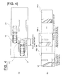
- FIG. 4 is a view for describing the general overview of the processing of the alignment unit 32
- FIG. 4(a) is a plan view illustrating the movement state of the vehicle V
- FIG. 4(b) is an image illustrating a general overview of alignment.
- the host vehicle V at the current moment is positioned at V1, and the host vehicle V at a single moment prior is positioned at V2. It is assumed that another vehicle V is positioned in the rear-side direction of the host vehicle V and is travelling parallel to the host vehicle V, and that the other vehicle V at the current moment is positioned at V3, and that the other vehicle V at a single moment prior is positioned at V4. Also, it is assumed that the host vehicle V has moved a distance d in a single moment.
- the phrase "at a single moment prior" may be a moment in the past by a time set in advance (e.g., a single control cycle) from the current moment, or may be a moment in the past by an arbitrary time.
- FIG. 4(b) a bird's-eye-view image PB t at the current moment is illustrated in FIG. 4(b) .
- the white lines drawn on the road surface are rectangular in this bird's-eye-view image PB t and are relatively accurate in a planar view, but collapsing occurs with the other vehicle V3.
- the white lines drawn on the road surface are rectangular and are relatively accurate in a planar view, but collapsing occurs with the other vehicle V4.
- vertical edges of a three-dimensional object appear as a straight-line group along the collapsing direction due to the process for converting the viewpoint to bird's-eye-view image data, but because a planar image on the road surface does not include vertical edges, such collapsing does not occur when the viewpoint has been converted.
- the alignment unit 32 carries out alignment of the bird's-eye-view images PB t and PB t-1 as described above on the data. When this is carried out, the alignment unit 32 offsets the bird's-eye-view image PB t-1 at a single moment prior, and matches the position with the bird's-eye-view image PB t at the current moment.
- the left-side image and the center image in FIG. 4(b) illustrate the state of being offset by a travel distance d'.
- the offset amount d' is the amount of movement in the bird's-eye-view image data that corresponds to the actual travel distance d of the host vehicle V illustrated in FIG. 4(a) , and is decided based on a signal from the vehicle speed sensor 20 and the time from a single moment prior to the current moment.
- the alignment unit 32 obtains the difference between the bird's-eye-view images PB t and PB t-1 , and generates differential image PD t data.
- the pixel values of the differential image PD t may be the absolute values of the pixel value differences between the bird's-eye-view images PB t and PB t-1 , or may be taken as "1" if the absolute value exceeds, or "0" if the absolute value does not exceed, a predetermined threshold value for purposes of adapting to variation in the illumination environment.
- the right image in FIG. 4(b) is the differential image PD t .
- the alignment unit 32 aligns the positions of the bird's-eye-view image at different times on a bird's-eye view, and this aligned bird's-eye-view image is obtained.
- this alignment processing can be carried out based on luminance in accordance with the desired detection precision or the type of object to be detected. This processing may involve strict alignment, which is performed with respect to the same point in time and the same position, or relaxed alignment, which involves ascertaining coordinates of the birds-eye-view images.
- the first three-dimensional object detection unit 33 detects a three-dimensional object based on the differential image PD t data illustrated in FIG. 4(b) .
- the first three-dimensional object detection unit 33 calculates the travel distance of the three-dimensional object in actual space.
- the first three-dimensional object detection unit 33 first generates a differential waveform when the three-dimensional object is detected and the travel distance is calculated.
- the travel distance of the three-dimensional object per unit time is used for calculating the traveling speed of the three-dimensional object. Then, the traveling speed of the three-dimensional object can be used in determining whether or not the three-dimensional object is a vehicle.
- the first three-dimensional object detection unit 33 sets a detection area in the differential image PD t .
- the three-dimensional object detection device 1 of the present example detects, as a detection object, another vehicle VX that the operator of the host vehicle should pay attention to, in particular, another vehicle VX that is travelling in a lane adjacent to the lane in which the host vehicle V is travelling and which has the potential for contact should the host vehicle V change lanes.
- two detection areas are set on the left and right sides of the host vehicle V among the images that are obtained by the camera 1.
- rectangular detection areas A1, A2 are set behind the host vehicle V, as illustrated in FIG.
- the other vehicle VX that has been detected in the detection areas A1, A2 is detected as a harmful object that is travelling in an adjacent lane that is adjacent to the lane in which the host vehicle V is travelling.
- detection areas A1, A2 may be set from a relative position with respect to the host vehicle V, or may be set based on the position of the white lines.
- the three-dimensional object detection device 1 may use, e.g., known white line recognition techniques.
- the first three-dimensional object detection unit 33 identifies, as ground lines L1, L2, the borders of the set detection areas A1, A2 on the host vehicle V side (borders along the traveling direction).
- a ground line refers to a line in which a three-dimensional object is in contact with the ground, but in the present embodiment, a ground line is not a line in contact with the ground, but is rather set in the manner described above. Even such being the case, the difference between the ground line according to the present embodiment and the normal ground line determined from the position of the other vehicle V is not exceedingly great as determined by experience, and there is no problem in actuality.
- FIG. 5 is a schematic view illustrating the manner in which the differential waveform is generated by the first three-dimensional object detection unit 33 shown in FIG. 3 .
- the first three-dimensional object detection unit 33 generates a differential waveform DW t from the portion that corresponds to the detection areas A1, A2 in the differential image PD t (drawing on the right in FIG. 4(b) ) calculated by the alignment unit 32.
- the first three-dimensional object detection unit 33 generates a differential waveform DW t along the collapsing direction of the three-dimensional object by viewpoint conversion.
- the differential waveform DW t is generated for the detection area A2 as well using the same procedure.
- the first three-dimensional object detection unit 33 defines a line La in the direction in which the three-dimensional object collapses in the differential image PD t data.
- the first three-dimensional object detection unit 33 then counts the number of difference pixels DP indicating a predetermined difference on the line La.
- the difference pixels DP indicating a predetermined difference are pixels that exceed a predetermined threshold value when the pixel values of the differential image PDt are absolute valuations of the difference in pixel values of the bird's-eye-view images PB t , PB t-1 , or are pixels that are indicated by "1" when the pixel values of the differential image PDt are represented by "0" and "1".
- the first three-dimensional object detection unit 33 counts the number of difference pixels DP, and thereafter determines the crossing point CP of the line La and the ground line L1.
- the first three-dimensional object detection unit 33 then correlates the crossing point CP and the count, decides the horizontal-axis position; i.e., the position on the axis in the vertical direction in the drawing on the right in FIG. 5 , based on the position of the crossing point CP, decides the vertical-axis position; i.e., the position on the axis in the lateral direction in the drawing on the right in FIG. 5 , from the count, and plots the positions as the count at the crossing point CP.
- the first three-dimensional object detection unit 33 defines the lines Lb, Lc, ... in the direction in which the three-dimensional object collapses, counts the number of difference pixels DP, decides the horizontal-axis position based on the position of each crossing point CP, decides the vertical-axis position from the count (the number of difference pixels DP), and plots the positions.
- the first three-dimensional object detection unit 33 repeats the above in sequence to form a frequency distribution and thereby generate a differential waveform DW t as illustrated in the drawing on the right in FIG. 5 .
- the lines La and Lb in the direction in which the three-dimensional object collapses have different distances that overlap the detection area A1, as illustrated in the drawing on the left in FIG. 5 . Accordingly, the number of difference pixels DP is greater on the line La than on the line Lb when it is assumed that the detection area A1 is filled with the difference pixels DP. For this reason, the first three-dimensional object detection unit 33 performs normalization based on the distance of overlap between the lines La, Lb in the direction in which the three-dimensional object collapses and the detection area A1 when the vertical-axis position is decided from the count of the difference pixels DP. In a specific example, there are six difference pixels DP on the line La and there are five difference pixels DP on the line Lb in the drawing on the left in FIG.
- the first three-dimensional object detection unit 33 divides the count by the overlapping distance or performs normalization in another manner.
- the values of the differential waveform DW t that correspond to the lines La, Lb in the direction in which the three-dimensional object collapses are thereby made substantially the same, as illustrated in the differential waveform DW t .
- the first three-dimensional object detection unit 33 calculates the travel distance by comparison with the differential waveform DW t-1 at a single moment prior. In other words, the first three-dimensional object detection unit 33 calculates the travel distance from the change in time of the differential waveforms DW t and DW t-1 .
- the first three-dimensional object detection unit 33 divides the differential waveform DW t into a plurality of small areas DW t1 to DW tn (where n is an arbitrary integer of 2 or greater), as illustrated in FIG. 6.
- FIG. 6 is a view illustrating the small areas DW t1 to DW tn divided by the first three-dimensional object detection unit 33.
- the small areas DW t1 to DW tn are divided so as to be mutually overlapping, as illustrated in, e.g., FIG. 6 .
- the small area DW t1 and the small area DW t2 overlap each other
- the small area DW t2 and the small area DW t3 overlap each other.
- the first three-dimensional object detection unit 33 determines the offset amount (the amount of movement in the horizontal-axis direction (vertical direction in FIG. 6 ) of the differential waveform) for each of the small areas DW t1 to DW tn .
- the offset amount is determined from the difference (distance in the horizontal-axis direction) between the differential waveform DW t-1 at a single moment prior and the differential waveform DW t at the current moment.
- the first three-dimensional object detection unit 33 moves the differential waveform DW t-1 at a single moment prior in the horizontal-axis direction for each of the small areas DW t1 to DW tn , and thereupon assesses the position (the position in the horizontal-axis direction) in which the error from the differential waveform DW t at the current moment is at a minimum, and determines as the offset amount the movement amount in the horizontal-axis direction at the position in which the error from the original position of the differential waveform DW t-1 is at a minimum.
- the first three-dimensional object detection unit 33 then counts the offset amount determined for each of the small areas DW t1 to DW tn and forms a histogram.
- FIG. 7 is a view illustrating an example of the histogram obtained by the first three-dimensional object detection unit 33.
- the offset amount which is the movement amount in which the error between the small areas DW t1 to DW tn and the differential waveform DW t-1 at a single moment prior is at a minimum.
- the first three-dimensional object detection unit 33 forms the offset amounts including the variability into a histogram and calculates the travel distance from the histogram.
- the first three-dimensional object detection unit 33 calculates the travel distance of the three-dimensional object from the maximum value in the histogram. In other words, in the example illustrated in FIG.
- the first three-dimensional object detection unit 33 calculates the offset amount indicating the maximum value of the histogram as the travel distance ⁇ *.
- the travel distance ⁇ * is the relative travel distance of the other vehicle V in relation to the host vehicle V. Accordingly, the first three-dimensional object detection unit 33 calculates the absolute travel distance based on the travel distance ⁇ * thus obtained and a signal from the vehicle speed sensor 20 when the absolute travel distance is to be calculated.
- the first three-dimensional object detection unit 33 may impart a weighting to each of the plurality of small areas DW t1 to DW tn , and count the offset amounts determined for each of the small areas DW t1 to DW tn in accordance with the weighting to form a histogram.
- FIG. 8 is a view illustrating the weighting used by the first three-dimensional object detection unit 33.
- a small area DW m (where m is an integer of 1 or greater and n - 1 or less) is flat.
- m is an integer of 1 or greater and n - 1 or less
- the first three-dimensional object detection unit 33 reduces the weighting of this type of small area DW m . This is because the flat small area DW m lacks a characteristic and there is a high possibility that an error will be magnified when the offset amount is calculated.
- a small area DW m+k (where k is an integer of n - m or less) has a great amount of fluctuation.
- the first three-dimensional object detection unit 33 increases the weighting of this type of small area DW m . This is because the small area DW m+k having a large amount of fluctuation is characteristic, and there is a high possibility that the offset amount will be accurately calculated. Weighting in this manner makes it possible to enhance the precision of calculating the travel distance.
- the differential waveform DW t is divided into a plurality of small areas DW t1 to DW tn in the present embodiment in order to enhance the precision of calculating the travel distance, but division into the small areas DW t1 to DW tn is not required when such high precision of calculating travel distance is not needed.
- the first three-dimensional object detection unit 33 calculates the travel distance from the offset amount of the differential waveform DW t when the error between the differential waveform DW t and the differential waveform DW t-1 is at a minimum.
- the method for determining the offset amount between the differential waveform DW t-1 at a single moment prior and the differential waveform DW t at the current moment is not limited to the details described above.
- the computer 30 is provided with a smear detection unit 34.
- the smear detection unit 34 detects an area in which a smear is generated from the captured image data obtained by the camera 10.
- a smear is a white-out phenomenon that is generated by, e.g., CCD image sensors, and therefore the smear detection unit 34 may be omitted when a camera 10 is employed that uses, e.g., a CMOS image sensor that does not generate this type of smear.
- FIG. 9 is a view illustrating the processing of the smear detection unit 34 and the calculation process for the differential waveform DW t according thereto.
- data from the captured image P in which a smear S is present is input to the smear detection unit 34.
- the smear detection unit 34 detects a smear S from the captured image P.
- CCD charge-coupled device
- a smear S is generated only downward in an image from a light source. For this reason, in this embodiment, areas are searched for that have a luminance value of at least a predetermined value from below to above in the image, and which continue in the vertical direction. Such areas are specified as smear S generation area.
- the smear detection unit 34 generates smear image SP data in which pixel values for the locations where the smear S is generated are assigned "1", and other locations are assigned "0". After generation, the smear detection unit 34 sends the smear image SP data to the viewpoint conversion unit 31.
- the viewpoint conversion unit 31 that has received input of the smear image SP data performs viewpoint conversion on this data to produce a bird's-eye-view state.
- the viewpoint conversion unit 31 generates smear bird's-eye-view image SB t data.
- the viewpoint conversion unit 31 sends the smear bird's-eye-view image SB t data to the alignment unit 32.
- the viewpoint conversion unit 31 sends the smear bird's-eye-view image SB t-1 data at a single moment prior to the alignment unit 32.
- the alignment unit 32 performs data-based alignment of the smear bird's-eye-view images SB t and SB t-1 .
- the specific alignment is similar to the case when alignment of the bird's-eye-view images PB t and PB t-1 is carried out using data.
- the alignment unit 32 carries out logical addition on the areas in which the smears S of the respective smear bird's-eye-view images SB t and SB t-1 have been generated. As a result, the alignment unit 32 generates mask image MP data. After generation, the alignment unit 32 sends the mask image MP data to the first three-dimensional object detection unit 33.
- the first three-dimensional object detection unit 33 zeroes the count of the frequency distribution for the locations corresponding to the areas in which the smears S have been generated in the mask image MP. Specifically, when the differential waveform DW t has been generated as shown in FIG. 9 , the first three-dimensional object detection unit 33 zeroes the count SC in accordance with the smear S, and generates a revised differential waveform DW t '.
- the first three-dimensional object detection unit 33 in the present embodiment determines the traveling speed of the vehicle V (camera 10) and determines the offset amount for a stationary object from the determined traveling speed. After the offset amount of the stationary object has been determined, the first three-dimensional object detection unit 33 calculates the travel distance of the three-dimensional object, ignoring the offset amount corresponding to the stationary object among the maximum values of the histogram.
- FIG. 10 is a view illustrating another example of the histogram obtained by the first three-dimensional object detection unit 33.
- a stationary object other than the other vehicle V is present within the view angle of the camera 10
- two maximum values ⁇ 1, ⁇ 2 appear in the resulting histogram.
- one of the two maximum values ⁇ 1, ⁇ 2 is the offset amount of the stationary object. Consequently, the first three-dimensional object detection unit 33 determines the offset amount for the stationary object from the traveling speed, ignores the maximum value that corresponds to the offset amount, and calculates the travel distance of the three-dimensional object using the remaining maximum value.
- the first three-dimensional object detection unit 33 stops calculating the travel distance.
- FIGS. 11 and 12 are flowcharts illustrating processes for detecting a three-dimensional object according to the present embodiment.
- data of a captured image P is inputted into the computer 30 from the camera 10, and a smear image SP is generated by the smear detection unit 34 (step S1).
- the viewpoint conversion unit 31 generates bird's-eye-view image PB t data from the data of the captured image P from the camera 10, and also generates smear bird's-eye-view image SB t data from the smear image SP data (S2).
- the alignment unit 32 then aligns the bird's-eye-view image PB t data and the bird's-eye-view image PB t-1 data at a single moment prior, and also aligns the smear bird's-eye-view image SB t data and the smear bird's-eye-view image SB t-1 data at a single moment prior (S3).
- the alignment unit 32 After this alignment, the alignment unit 32 generates differential image PD t data and also generates mask image MP data (S4).
- the first three-dimensional object detection unit 33 generates the differential waveform DW t from the differential image PD t data and the differential image PD t-1 data at a single moment prior (S5).
- the first three-dimensional object detection unit 33 After generating the differential waveform DW t , the first three-dimensional object detection unit 33 zeroes the count corresponding to the generation area of the smear S in the differential waveform DW t and suppresses effects due to the smear S (S6).
- the first three-dimensional object detection unit 33 assesses whether the peak of the differential waveform DW t is equal to or greater than a first threshold value ⁇ (S7).
- This first threshold value ⁇ is determined and set as the result, e.g., of prior experimentation, but the value may be set by the three-dimensional object assessment unit 38 illustrated in FIG. 31 .
- the peak of the differential waveform DW t is at or above the first threshold value ⁇ , specifically, when there is little difference, it is concluded that a three-dimensional object is not present in the captured image P.
- the first three-dimensional object detection unit 33 assesses that no three-dimensional object is present, and that another vehicle is not present ( FIG. 12 : S16). The processing shown in FIGS. 11 and 12 is thus ended.
- the first three-dimensional object detection unit 33 assesses that a three-dimensional object is present, and the differential waveform DW t is divided into the plurality of small areas DW t1 to DW tn (S8).
- the first three-dimensional object detection unit 33 carries out weighting for each small area DW t1 to DW tn (S9).
- the first three-dimensional object detection unit 33 calculates the offset amount of each small area DW t1 to DW tn (S10), and generates a histogram taking into account the weightings (S11).
- the first three-dimensional object detection unit 33 then calculates the relative travel distance, which is the travel distance of the three-dimensional object with respect to the host vehicle V based on the histogram (S12). Next, the first three-dimensional object detection unit 33 calculates the absolute traveling speed of the three-dimensional object from the relative travel distance (S 13). At this time, the first three-dimensional object detection unit 33 takes the time derivative of the relative travel distance to calculate the relative traveling speed, and adds the host vehicle speed detected by the vehicle speed sensor 20 to calculate the absolute traveling speed.
- the first three-dimensional object detection unit 33 assesses whether the relative traveling speed of the three-dimensional object is 10 km/h or greater and the relative traveling speed of the three-dimensional object with respect to the host vehicle V is +60 km/h or less (S 14). If both are true (S14: YES), then the first three-dimensional object detection unit 33 assesses that the three-dimensional object is another vehicle V (S15). The process illustrated in FIGS. 11 and 12 is then ended. On the other hand, if either is not true (S14: NO), then the first three-dimensional object detection unit 33 assesses that another vehicle is not present (S16). The process illustrated in FIGS. 11 and 12 is then ended.
- the area rearward of the host vehicle V is taken to be detection areas A1, A2, and emphasis is placed on detection of another vehicle VX travelling in an adjacent lane that is adjacent to the lane in which the host vehicle is travelling and to which attention should be paid during travel of the host vehicle V, in particular, on whether or not there is potential for contact when the host vehicle V changes lanes.
- This is for assessing whether or not there is a potential for contact with another vehicle VX that is travelling in an adjacent lane that is adjacent to the lane in which the host vehicle is travelling, when the host vehicle V changes lanes. For this reason, the process of step S14 is carried out.
- step S 14 this is also referred to as assessing another vehicle V that represents a problem when changing lanes.
- step S 14 the following effects result when it is assessed whether the absolute traveling speed of the three-dimensional object is 10 km/h or greater and whether the absolute traveling speed of the three-dimensional object relative to the host vehicle V is +60 km/h or less.
- the absolute traveling speed of a stationary object is detected at a few km/h due to errors in attachment of the camera 10.
- the relative speed of a three-dimensional object relative to the host vehicle V is detected at a speed that exceeds +60 km/h due to noise.
- assessing whether the relative speed is +60 km/h or less can decrease the chance of erroneous detection due to noise.
- step S14 it may be assessed that the absolute traveling speed is not negative or 0 km/h.
- a warning sound may be emitted to the operator of the host vehicle, or a display corresponding to a warning may be provided using a predetermined display device.
- Pixels exhibiting a predetermined difference in the differential image PD t data refers to pixels for which there has been a change in the images at different points in time, or in other words, locations at which a three-dimensional object is present.
- the number of pixels along the direction in which the three-dimensional object collapses is counted and used to form a frequency distribution, thereby producing a differential waveform DW t .
- a differential waveform DW t is generated from the information in the height direction with respect to the three-dimensional object.
- the travel distance of the three-dimensional object is calculated from the temporal change in the differential waveform DW t including the information in the height direction.
- the detection location prior to the change in time and the detection location after the change in time tend to be the same location on the three-dimensional object by virtue of being specified with the inclusion of information in the height direction.
- the travel distance is thus calculated from the change in time at the same location, and the precision of calculating the travel distance can be improved.
- the count of the frequency distribution is zeroed at locations corresponding to areas in which a smear S is generated in the differential waveform DW t .
- waveform locations in the differential waveform DW t that are generated by the smear S are removed, making it possible to prevent conditions in which the smear S is erroneously identified as a three-dimensional object.
- the travel distance of the three-dimensional object is calculated from the offset amount of the differential waveform DW t when the error in the differential waveform DW t generated at different points in time is at a minimum. This allows the travel distance to be calculated from the offset amount of one-dimensional information as a waveform, which allows computation cost to be kept low when the travel distance is calculated.
- the differential waveform DW t generated at different points in time is divided into a plurality of small areas DW t1 to DW tn .
- Dividing the differential waveform into a plurality of small areas DW t1 to DW tn allows a plurality of waveforms representing the locations of the three-dimensional object to be obtained.
- the travel distance of the three-dimensional object is calculated. Therefore, the offset amount for each location of the three-dimensional object is determined, and the travel distance is determined from the plurality of offset amounts, allowing improvement in the calculation precision of the travel distance.
- weightings are applied to each of the plurality of small areas DW t1 to DW tn , and the offset amounts determined for each of the small areas DW t1 to DW tn are counted in accordance with weighting to produce a histogram.
- the weightings are increased for characteristic areas, and the weightings are decreased for uncharacteristic areas, thereby allowing more suitable calculation of the travel distance. Consequently, the precision of the travel distance calculation can be further improved.
- the weightings increase with increasing difference between the maximal and minimal count values of the number of pixels exhibiting a predetermined difference in each small area DW t1 to DW tn in the differential waveform DW t . Therefore, the weightings are increased for areas with characteristic fluctuations that have a large difference between maximum and minimum values, and the weightings are decreased for flat areas with small fluctuation. Because areas with large amounts of fluctuation allow accurate determination of the offset amount more readily than flat areas from a geometric standpoint, the weightings are increased for areas in which the difference between maximal and minimal values is large, allowing the precision of travel distance calculation to be further improved.
- the travel distance of the three-dimensional object is calculated from the extreme value of the histogram obtained by counting offset amounts determined for each of the small areas DW t1 to DW tn . Therefore, even if there is some variation in the offset amounts, the travel distance can be calculated with higher accuracy from the maximum value.
- the speed of the host vehicle V is determined based on signals from the vehicle speed sensor 20, but embodiments are not restricted thereto, and the speed can be estimated from a plurality of images at different points in time. In this case, a vehicle speed sensor is unnecessary, allowing simplification of the configuration.
- a captured image at the current moment and an image at a single moment prior are converted to bird's-eye views, the converted bird's-eye views are aligned, a differential image PD t is then generated, and the generated differential image PD t is evaluated along the collapsing direction (the direction in which the three-dimensional object collapses when the captured image is converted to the bird's-eye view) to generate a differential waveform DW t , but no limitation is imposed thereby.
- a differential image PD t is generated from the difference between the aligned images, and the differential image PD t can be evaluated along the collapsing direction of the three-dimensional object when the differential image PD t is converted to a bird's-eye view.
- the bird's-eye-view image data PB t at a current moment and the bird's-eye-view image data PB t-1 of a single moment prior (past) are aligned as illustrated in FIG. 4(b) , whereupon the differential image PD t thereof is generated, and the differential image PD t is evaluated along a direction corresponding to the collapsing direction as shown in FIG. 5 , thereby generating a differential waveform DW t .
- the bird's-eye-view image data PB t , PB t-1 at the current moment and at a single moment prior may be evaluated along a direction corresponding to the collapsing direction as shown in FIG.
- FIG. 13 is a view illustrating the capture range of the camera 10 of FIG. 3 .
- FIG. 13(a) is a plan view
- FIG. 13(b) is a perspective view in real space in the rearward direction from the host vehicle V1. As shown in FIG.
- the camera 10 has a predetermined view angle a, and the rearward direction from the host vehicle V1 included in this predetermined view angle a is captured.
- the view angle a of the camera 10 is set so that adjacent lanes are included in the capture range of the camera 10 in addition to the lane in which the host vehicle V1 is travelling.
- the detection areas A1, A2 in the present example are trapezoidal in a plan view (bird's-eye-view state), and the position, size, and shape of the detection areas A1, A2 are decided based on distances d 1 to d 4 .
- the detection areas A1, A2 of the example illustrated in the drawing are not limited to being trapezoidal, and may also be rectangular or another shape in a bird's-eye-view state, as illustrated in FIG. 2 .
- the distance d1 is the distance from the host vehicle V1 to the ground lines L1, L2.
- the ground lines L1, L2 refer to lines in which a three-dimensional object, which is present in a lane adjacent to the lane in which the host vehicle V1 is traveling, is in contact with the ground.
- the purpose is to detect another vehicle V2 or the like (including two-wheeled vehicles or the like) traveling in the left or right lane behind the host vehicle V1 and adjacent to the lane of the host vehicle V1.
- the distance d 1 which is the distance to the positions of the ground lines L1, L2 of the other vehicle V2, can be decided so as to be substantially fixed, from the distance d1 from the host vehicle V1 to a white line W and the distance d12 from the white line W to the position to which the other vehicle V2 is predicted to travel.
- the distance d1 is not limited to being fixedly decided, and may be variable.
- the computer 30 identifies the position of the white line W in relation to the host vehicle V1 using white line recognition or another technique, and the distance d11 is decided based on the position of the identified white line W.
- the distance d1 is thereby variably set using the decided distance d11.
- the position in which the other vehicle V2 is travelling (the distance d12 from the white line W) and the position in which the host vehicle V1 is travelling (the distance d11 from the white line W) are decided for the most part, and the distance d1 thus is fixedly decided.
- a distance d2 is the distance extending from the rear end part of the host vehicle V1 in the vehicle progress direction.
- the distance d2 is decided so that the detection areas A1, A2 are accommodated within at least the view angle a of the camera 10.
- the distance d2 is set so as to be in contact with a range partitioned within the view angle a.
- the distance d3 indicates the length of the detection areas A1, A2 in the vehicle progression direction.
- the distance d3 is decided based on the size of the three-dimensional object to be detected.
- the object to be detected is another vehicle V2 or the like, and therefore the distance d3 is set to a length that includes another vehicle V2.
- the distance d4 indicates the height of the other vehicle V2 in real space, which has been set so as to include the tires, as illustrated in FIG. 13(b) .
- the distance d4 is the length illustrated in FIG. 13(a) .
- the distance d4 may also be a length that does not include lanes further adjacent to the left and right adjacent lanes in the bird's-eye-view image (i.e., "next-next" lanes two lanes away).
- the distances d1 to d4 are decided, and the position, size, and shape of the detection areas A1, A2 are thereby decided. More specifically, the position of the top side b1 of the detection areas A1, A2 that form a trapezoid is decided by the distance d1. The starting position C1 of the top side b1 is decided by the distance d2. The end position C2 of the top side b1 is decided by the distance d3. The lateral side b2 of the detection areas A1, A2 that form a trapezoid is decided by a straight line L3 extending from the camera 10 toward the starting position C1.
- the lateral side b3 of the detection areas A1, A2 that form a trapezoid is decided by a straight line L4 extending from the camera 10 toward the end position C2.
- the position of the lower side b4 of the detection areas A1, A2 that form a trapezoid is decided by the distance d4.
- the areas surrounded by the sides b1 to b4 are the detection areas A1, A2.
- the detection areas A1, A2 are regular squares (rectangles) in real space rearward from the host vehicle V1, as illustrated in FIG. 13(b) .
- the viewpoint conversion unit 31 accepts input of captured image data of a predetermined area captured by the camera 10.
- the viewpoint conversion unit 31 converts the viewpoint of the inputted captured image data into bird's-eye-view image data, which represents a bird's-eye-view state.
- a bird's-eye-view state is a state of viewing from the viewpoint of an imaginary camera that is looking down from above, e.g., vertically downward (or slightly inclined downward).
- Viewpoint conversion can be carried out using the technique described in, e.g., Japanese Laid-Open Patent Application No. 2008-219063 .
- the luminance difference calculation unit 35 calculates luminance differences in the bird's-eye-view image data, which has undergone viewpoint conversion by the viewpoint conversion unit 31, in order to detect the edges of a three-dimensional object included in the bird's-eye-view image.
- the luminance difference calculation unit 35 calculates, for each of a plurality of positions along a vertical imaginary line extending along the vertical direction in real space, the luminance difference between two pixels near each position.
- the luminance difference calculation unit 35 is capable of calculating the luminance difference by a method for setting a single vertical imaginary line extending in the vertical direction in real space, or a method for setting two vertical imaginary lines.
- the luminance difference calculation unit 35 sets a first vertical imaginary line that corresponds to a line segment extending in the vertical direction in real space, and a second vertical imaginary line that is different from the first vertical imaginary line and that corresponds to a line segment extending in the vertical direction in real space, for the bird's-eye-view image that has been subjected to viewpoint conversion.
- the luminance difference calculation unit 35 determines the luminance difference between a point on the first vertical imaginary line and a point on the second vertical imaginary line in continuous fashion along the first vertical imaginary line and the second vertical imaginary line. The operation of the luminance difference calculation unit 35 is described in detail below.
- the luminance difference calculation unit 35 sets a first vertical imaginary line La (hereinbelow referred to as attention line La) that corresponds to a line segment extending in the vertical direction in real space and that passes through the detection area A1, as illustrated in FIG. 14(a) .
- the luminance difference calculation unit 35 sets a second vertical imaginary line Lr (hereinbelow referred to as reference line Lr) that is different from the attention line La, corresponds to a line segment extending in the vertical direction in real space, and passes through the detection area A1.
- the reference line Lr is set to a position at a distance from the attention line La by a predetermined distance in real space.
- the lines that correspond to the line segments extending in the vertical direction in real space are lines that spread out in a radial fashion from the position Ps of the camera 10 in a bird's-eye-view image. These lines spreading out in a radial fashion are lines that follow the collapsing direction of the three-dimensional object when converted to a bird's-eye view.
- the luminance difference calculation unit 35 sets an attention point Pa on the attention line La (a point on the first vertical imaginary line).
- the luminance difference calculation unit 35 sets a reference point Pr on the reference line Lr (a point on the second vertical imaginary line).
- the attention line La, the attention point Pa, the reference line Lr, and the reference point Pr have the relationship in real space illustrated in FIG. 14(b) . It is apparent from FIG. 14(b) that the attention line La and the reference line Lr are lines extending in the vertical direction in real space, and that the attention point Pa and the reference point Pr are points set to substantially the same height in real space.
- the attention point Pa and the reference point Pr are not necessarily required to be rigorously kept at the same height, and a certain amount of error that still allows for the attention point Pa and the reference point Pr to be deemed to be at the same height is allowed.
- the luminance difference calculation unit 35 determines the luminance difference between the attention point Pa and the reference point Pr. If the luminance difference between the attention point Pa and the reference point Pr is great, it is possible that an edge is present between the attention point Pa and the reference point Pr. Accordingly, the edge line detection unit 36 illustrated in FIG. 3 detects an edge line based on the luminance difference between the attention point Pa and the reference point Pr.
- FIG. 15 is a view for describing the detailed operation of the luminance difference calculation unit 35.
- FIG. 15(a) illustrates a bird's-eye-view image of the bird's-eye-view state
- FIG. 15(b) is an enlarged view of a part B1 of the bird's-eye-view image illustrated in FIG. 15(a) .
- FIG. 15 only the detection area A1 is illustrated and described, but the luminance difference is calculated using the same procedure for detection area A2.
- the other vehicle V2 When the other vehicle V2 is being depicted in the captured image captured by the camera 10, the other vehicle V2 appears in the detection area A1 in the bird's-eye-view image, as illustrated in FIG. 15(a) .
- the attention line La is set on a rubber portion of a tire of the other vehicle V2 in the bird's-eye-view image in FIG. 15(b) , as illustrated in the enlarged view of area B1 in FIG. 15(a) .
- the luminance difference calculation unit 35 sets the reference line Lr.
- the reference line Lr is set along the vertical direction in a position set at a predetermined distance in real space from the attention line La.
- the reference line Lr is set in a position at a distance of 10 cm away in real space from the attention line La.
- the reference line Lr is thereby set on the wheel of the tire of the other vehicle V2, e.g., at a distance that corresponds to 10 cm from the rubber of the tire of the other vehicle V2 in the bird's-eye-view image.
- the luminance difference calculation unit 35 sets a plurality of attention points Pa1 to PaN on the attention line La.
- attention points Pa1 to Pa6 (hereinbelow simply referred to as attention point Pai when indicating an arbitrary point) are set for convenience of description.
- An arbitrary number of attention points Pa may be set on the attention line La.
- N attention points Pa are set on the attention line La.
- the luminance difference calculation unit 35 subsequently sets the reference points Pr1 to PrN so as to have the same height as the attention points Pa1 to PaN in real space.
- the luminance difference calculation unit 35 calculates the luminance difference between attention point Pa and reference point Pr pairs at the same height.
- the luminance difference calculation unit 35 thereby calculates the luminance difference between two pixels for each of the plurality of positions (1 - N) along the vertical imaginary line extending in the vertical direction in real space.
- the luminance difference calculation unit 35 calculates the luminance difference between, e.g., the first attention point Pa1 and the first reference point Pr1, and calculates the luminance difference between the second attention point Pa2 and the second reference point Pr2.
- the luminance difference calculation unit 35 thereby determines the luminance difference in continuous fashion along the attention line La and the reference line Lr. In other words, the luminance difference calculation unit 35 sequentially determines the luminance difference between the third to N th attention points Pa3 to PaN and the third to N th reference points Pr3 to PrN.
- the luminance difference calculation unit 35 repeats the process of setting the above-described reference line Lr, setting the attention point Pa, setting the reference point Pr, and calculating the luminance difference while shifting the attention line La within the detection area A1. In other words, the luminance difference calculation unit 35 repeatedly executes the above-described process while changing the positions of the attention line La and the reference line Lr by the same distance in real space along the direction in which the ground line L1 extends.
- the luminance difference calculation unit 35 e.g., sets the line that was the reference line Lr in the previous process to be the attention line La, sets the reference line Lr in relation to the attention line La, and sequentially determines the luminance difference.
- the edge line detection unit 36 detects the edge line from the continuous luminance difference calculated by the luminance difference calculation unit 35. For example, in the case illustrated in FIG. 15(b) , the first attention point Pa1 and the first reference point Pr1 are positioned at the same tire portion, and the luminance difference is therefore small. On the other hand, the second to sixth attention points Pa2 to Pa6 are positioned at the rubber portions of the tire, and the second to sixth reference points Pr2 to Pr6 are positioned at the wheel portion of the tire. Therefore, the luminance difference between the second to sixth attention points Pa2 to Pa6 and the second to sixth reference points Pr2 to Pr6 is great. Accordingly, the edge line detection unit 36 is capable of detecting that an edge line is present between the second to sixth attention points Pa2 to Pa6 and the second to sixth reference points Pr2 to Pr6 where the luminance difference is great.
- the edge line detection unit 36 first assigns an attribute to the i th attention point Pai from the luminance difference between the i th attention point Pai (coordinates (xi, yi)) and the i th reference point Pri (coordinates (xi', yi')) in accordance with formula 1 noted below.
- t represents a threshold value
- I(xi, yi) represents the luminance value of the i th attention point Pai
- I(xi', yi') represents the luminance value of the i th reference point Pri.
- the attribute s(xi, yi) of the attention point Pai is '1' when the luminance value of the attention point Pai is greater than the luminance value obtained by adding the threshold value t to the reference point Pri.
- the attribute s(xi, yi) of the attention point Pai is '-1' when the luminance value of the attention point Pai is less than the luminance value obtained by subtracting the threshold value t from the reference point Pri.
- the attribute s(xi, yi) of the attention point Pai is '0' when the luminance value of the attention point Pai and the luminance value of the reference point Pri are in a relationship other than that stated above.
- the edge line detection unit 36 assesses whether the attention line La is an edge line from the continuity c(xi, yi) of the attribute s along the attention line La based on the following formula 2.
- the continuity c(xi, yi) is '1' when the attribute s(xi, yi) of the attention point Pai and the attribute s(xi + 1, yi + 1) of the adjacent attention point Pai + 1 are the same.
- the continuity c(xi, yi) is '0' when the attribute s(xi, yi) of the attention point Pai and the attribute s(xi + 1, yi + 1) of the adjacent attention point Pai + 1 are not the same.
- the edge line detection unit 36 determines the sum of the continuities c of all the attention points Pa on the attention line La.
- the edge line detection unit 36 divides the sum of the continuities c thus determined by the number N of attention points Pa to thereby normalize the continuity c.
- the edge line detection unit 36 assesses the attention line La to be an edge line when the normalized value has exceeded a threshold value ⁇ .
- the threshold value ⁇ is set in advance, e.g., by experimentation.
- the edge line detection unit 36 assesses whether the attention line La is an edge line based on formula 3 noted below. The edge line detection unit 36 then assesses whether all of the attention lines La drawn on the detection area A1 are edge lines. ⁇ c xi yi / N > ⁇
- the second three-dimensional object detection unit 37 detects a three-dimensional object based on the amount of edge lines detected by the edge line detection unit 36.
- the three-dimensional object detection device 1 detects an edge line extending in the vertical direction in real space. Detecting many edge lines extending in the vertical direction indicates that there is a high possibility that a three-dimensional object is present in the detection areas A1, A2. Accordingly, the second three-dimensional object detection unit 37 detects a three-dimensional object based on the amount of edge lines detected by the edge line detection unit 36. Moreover, the second three-dimensional object detection unit 37 determines whether the edge lines detected by the edge line detection unit 36 are true edge lines prior to detecting the three-dimensional object.
- the second three-dimensional object detection unit 37 assesses whether, on an edge line, a change in luminance along the edge line of the bird's-eye-view image is greater than a predetermined threshold value.
- a predetermined threshold value When the change in luminance on the edge lines in the bird's-eye-view image is greater than the threshold value, the edge lines are determined to have been detected by errant assessment.
- the change in luminance on the edge lines in the bird's-eye-view image is not greater than the threshold value, it is assessed that the edge lines are correct.
- the threshold value is set in advance, e.g., by experimentation.
- FIG. 16 is a view illustrating the luminance distribution on the edge line
- FIG. 16(a) illustrates the edge line and the luminance distribution when another vehicle V2 as a three-dimensional object is present in the detection area A1
- FIG. 16(b) illustrates the edge line and the luminance distribution when a three-dimensional object is not present in the detection area A1.
- the attention line La set on the tire rubber portion of the other vehicle V2 in the bird's-eye-view image is an edge line.
- the change in luminance on the attention line La in the bird's-eye-view image is gradual. This is due to the image captured by the camera 10 being converted in viewpoint to a bird's-eye-view image, whereby the tire of the other vehicle V2 is stretched within the bird's-eye-view image.
- the attention line La set in the white character portion "50" drawn on the road surface in the bird's-eye-view image is assumed to have been errantly assessed to be an edge line, as illustrated in FIG. 16(b) .
- the change in luminance on the attention line La in the bird's-eye-view image has a large amount of fluctuation. This is because, on the edge line, the road and other portions of low luminance are mixed with the portions of high luminance in the white characters.
- the second three-dimensional object detection unit 37 assesses whether an edge line has been detected by errant assessment based on differences in the luminance distribution on the attention line La as described above.
- the second three-dimensional object detection unit 37 determines that the edge line has been detected by errant assessment when the change in luminance along the edge line is greater than a predetermined threshold value.
- the edge line is thus not to be used for detecting a three-dimensional object.
- a reduction in precision of detecting a three-dimensional object is thereby suppressed when white characters such as "50" on the road surface, roadside vegetation, and the like are assessed to be edge lines.
- the second three-dimensional object detection unit 37 calculates the change in luminance of the edge line using formula 4 or 5 noted below.
- the change in luminance of the edge line corresponds to the evaluation value in real space in the vertical direction.
- Formula 4 evaluates the luminance distribution using the total value of the square of the difference between the i th luminance value I(xi, yi) and the adjacent i th + 1 luminance value I(xi + 1, yi + 1) on the attention line La.
- Formula 5 evaluates the luminance distribution using the total value of the absolute value of the difference between the i th luminance value I(xi, yi) and the adjacent i th +1 luminance value I(xi + 1, yi + 1) on the attention line La.
- the attribute b(xi, yi) of the attention point Pa(xi, yi) is '1' when the absolute value of the luminance difference between the luminance value of the attention point Pai and the luminance value of the reference point Pri is greater than the threshold value t2.
- the attribute b(xi, yi) of the attention point Pai is '0.'
- the threshold value t2 is set in advance, e.g., by experimentation, so that the attention line La is not assessed to be on the same three-dimensional object.
- the second three-dimensional object detection unit 37 then sums the attribute b for all of the attention points Pa on the attention line La and determines the evaluation value in the vertical equivalent direction to assess whether the edge line is correct.
- FIGS. 17 and 18 are flow charts illustrating the details of the method for detecting the three-dimensional object in this embodiment.
- the process involved with detection area A1 will be described for the sake of convenience, but the same process is executed for the detection area A2 as well.
- step S21 a predetermined area specified by the view angle a and the attachment position is captured by the camera 10, as shown in FIG. 17 .
- the viewpoint conversion unit 31 receives input of the captured image data captured by the camera 10 in step S21, and, in step S22, converts the viewpoint and generates bird's-eye-view image data.
- step S23 the luminance difference calculation unit 35 sets the attention line La on the detection area A1. At this time, the luminance difference calculation unit 35 sets a line corresponding to a line extending in the vertical direction in real space as the attention line La.
- step S24 the luminance difference calculation unit 35 sets the reference line Lr on the detection area A1. At this time, the luminance difference calculation unit 35 sets, as the reference line Lr, a line that corresponds to a line segment extending in the vertical direction in real space, and that also is separated by a predetermined distance in real space from the attention line La.
- step S25 the luminance difference calculation unit 35 sets a plurality of attention points Pa on the attention line La.
- the luminance difference calculation unit 35 sets attention points Pa in an amount that will not cause problems during edge detection by the edge line detection unit 36.
- step S26 the luminance difference calculation unit 35 sets reference points Pr so that the attention points Pa and the reference points Pr are at substantially the same height in real space. The attention points Pa and the reference points Pr thereby line up in substantially the horizontal direction, and the edge line extending in the vertical direction in real space is more readily detected.
- step S27 the luminance difference calculation unit 35 calculates the luminance difference between the attention points Pa and the reference points Pr at the same height in real space.
- the edge line detection unit 36 calculates the attribute s of the attention points Pa in accordance with formula 1 described above.
- step S28 the edge line detection unit 36 then calculates the continuity c of the attribute s of the attention points Pa in accordance with formula 2 described above.
- step S29 the edge line detection unit 36 furthermore determines whether a value obtained by normalizing the sum of the continuities c is greater than a threshold value ⁇ , in accordance with formula 3.
- the edge line detection unit 36 detects the attention line La as an edge line in step S30. The process then proceeds to step S31.
- the edge line detection unit 36 does not detect the attention line La as an edge line, and the process proceeds to step S31.
- this threshold value ⁇ can be set in advance, it may also be varied in accordance with the control instructions from the controller 39.
- step S31 the computer 30 determines whether the processes of steps S23 to S30 have been executed for all the attention lines La that can be set on the detection area A1. When it has been determined that the above processes have not been carried out for all the attention lines La (S31: No), the process returns to step S23, sets a new attention line La, and repeats the process through step S31. On the other hand, when it has been determined that the processes have been carried out for all the attention lines La (S31: Yes), the process proceeds to step S32 of FIG. 18 .
- the second three-dimensional object detection unit 37 calculates the change in luminance along the edge line for each edge line detected in step S30 of FIG. 17 .
- the second three-dimensional object detection unit 37 calculates the change in luminance of edge lines in accordance with any of formulas 4, 5, and 6.
- step S33 the second three-dimensional object detection unit 37 excludes, from among the edge lines, edge lines in which the change in luminance is greater than a predetermined threshold value. In other words, when an edge line having a large change in luminance is not determined to be a correct edge line, the edge line is not used for detecting a three-dimensional object.
- the predetermined threshold value is determined in advance, e.g., by experimentation, and is set based on the change in luminance that occurs due to characters on the road surface, roadside vegetation, and the like.
- the second three-dimensional object detection unit 37 determines whether the amount of edge lines is a second threshold value ⁇ or higher.
- the second threshold value ⁇ is set in advance as determined, e.g., by experimentation. For example, when a four-wheeled vehicle is set as the three-dimensional object that is to be detected, the second threshold value ⁇ is set based on the number of edge lines of a four-wheeled vehicle appearing in the detection area A1 by, e.g., prior experimentation.
- the second three-dimensional object detection unit 37 detects the presence of the three-dimensional object in the detection area A1.
- the second three-dimensional object detection unit 37 assesses that a three-dimensional object is not present in the detection area A1.
- the processing illustrated in FIGS. 17 and 18 then ends.
- the detected three-dimensional object may be assessed to be another vehicle VX that is travelling in an adjacent lane that is adjacent to the lane in which the host vehicle V is travelling, or may be assessed as to whether the detected three-dimensional object is another vehicle VX that is travelling in an adjacent lane with consideration of the relative speed of the detected three-dimensional object with respect to the host vehicle V.
- the second threshold value ⁇ may be set in advance as described above or may vary in accordance with control instructions from the controller 39 illustrated in FIG. 31 .
- the three-dimensional object present in the detection areas A1, A2 is detected by the three-dimensional object detection method utilizing the edge information of the present embodiment. Therefore, a vertical imaginary line is set as a line segment that extends in the vertical direction in real space with respect to the bird's-eye-view image. Then, the luminance difference between two pixels near each position is calculated for each of a plurality of positions along the vertical imaginary line, and the presence of a three-dimensional object can be determined based on the continuity between the luminance differences.
- the attention line La corresponding to the line segment extending in the vertical direction in real space and the reference line Lr that is different from the attention line La are set for the detection areas A1, A2 in the bird's-eye-view image.
- the luminance difference between the attention point Pa on the attention line La and the reference point Pr on the reference line Lr is continuously determined along the attention line La and the reference line Lr.
- the luminance difference between the attention line La and the reference line Lr is determined.
- the luminance difference at two points of substantially the same height near a vertical imaginary line is determined. Specifically, the luminance difference between an attention point Pa on an attention line La and a reference point Pr on a reference line Lr is determined at substantially the same height in real space, and thus it is possible to clearly detect the difference in luminance when an edge that extends in the vertical direction is present.
- FIG. 19 is a view illustrating an image example for describing the processing of the edge line detection unit 36.
- This image example is an image in which a first stripe pattern 101 and a second stripe pattern 102 are adjacent to each other, the first stripe pattern 101 indicating a stripe pattern in which areas of high luminance and areas of low luminance are repeated, and the second stripe pattern 102 indicating a stripe pattern in which areas of low luminance and areas of high luminance are repeated. Also, in this image example, areas of the first stripe pattern 101 in which the luminance is high, and areas of the second stripe pattern 102 in which the luminance is low are adjacent to each other, and areas of the first stripe pattern 101 in which the luminance is low, and areas of the second stripe pattern 102 in which the luminance is high are adjacent to each other. A location 103 positioned on the boundary between the first stripe pattern 101 and the second stripe pattern 102 tends not to be perceived as an edge by human perception.
- the location 103 is identified as an edge when edges are detected only by luminance difference.
- the edge line detection unit 36 determines the location 103 to be an edge line only when there is continuity in the attributes of the luminance difference, in addition to the luminance difference at the location 103. Therefore, the edge line detection unit 36 is capable of suppressing errant determination in which the location 103, which is not identified as an edge line by human perception, is identified as an edge line, and edges can be detected in accordance with human perception.
- assessment that an edge line has been detected by errant determination is made when the change in luminance of an edge line detected by the edge line detection unit 36 is greater than a predetermined threshold value.
- the captured image obtained by the camera 10 is converted to a bird's-eye-view image
- the three-dimensional objects included in the captured image tend to appear stretched in the bird's-eye-view image.
- changes in the luminance of the bird's-eye-view image in the stretching direction tend to be small because the tire as a single location is stretched.
- the three-dimensional object detection device 1 of this example has a three-dimensional object assessment unit 38 for making the final assessment as to whether there is a three-dimensional object based on the detection results of the first three-dimensional object detection unit 33 and the detection results of the second three-dimensional object detection unit 37, and a controller 39 for operating a water droplet removal device 41 depending on whether water drops are attached to the lens as detected by the water droplet detection unit 40.
- FIG. 24A is a perspective view illustrating the camera 10 which is the image capturing means, as viewed from the left and rear of the vehicle.
- the lens 11 or capture filter
- FIG. 24A is a perspective view illustrating the camera 10 which is the image capturing means, as viewed from the left and rear of the vehicle.
- the lens 11 or capture filter
- the lens 11 that constitutes an optical capture system is included in the camera 10, but by mounting the camera on the outside of the vehicle, water droplets that are thrown up from the road surface or rain droplets often attach to the lens 11 which is the outer surface of the camera 10.
- the water droplet removal device 41 operates to remove the water droplets. Erroneous detection of water droplets as three-dimensional objects is thereby prevented.
- FIG. 26(a) is a view illustrating a plan view of a captured image for describing the method for detecting water droplets using a captured image obtained by the camera 10.
- the attention points are set for all of the pixels of the captured image, or for respective pixels of specific areas, e.g., areas within the captured image corresponding to detection areas A1 and A2 shown in FIG. 2 .
- FIG. 26(a) shows a state in which the attention point has been set for a single pixel.
- an imaginary circle of a predetermined radius centered on this attention point is hypothesized. This imaginary circle corresponds to the border of the water droplet. This draws on the fact that, for many water droplets, the border will be circular due to the involvement of surface tension.
- first reference points are set inside the imaginary circle that has been hypothesized
- outer reference points that are outside the imaginary circle are set on straight lines connecting the attention point and the respective inner reference points.
- the inner reference points are set at positions that are separated from the attention point by a 1-pixel diagonal line
- the outer reference points are set at positions that are separated from the attention point by a 5-pixel diagonal line, for example, as shown in FIG. 26(b) .
- the radius of the imaginary circle and the setting positions of the inner reference points and the outer reference points can be selected to have suitable values based on the size of the water droplets and the frequency of water droplet attachment to the lens, as determined by experience.
- a plurality of imaginary circle radii may be set for one pixel.
- a total of five points at the upper center part, the upper left part, the upper right part, the lower left part, and the lower right part inside the imaginary circle are set as inner reference points, and a total of five points at the upper center part, the upper left part, the upper right part, the lower left part, and the lower right part outside of the imaginary circle are set as outer reference points.
- the upper center part is obtained on the assumption that the water droplet is made prominent by the headlights of a trailing vehicle in the same lane
- the upper left part and upper right part are similarly obtained on the assumption that the water droplet is made prominent by the headlights of trailing vehicles in the left and right adjacent lanes
- the lower left part and lower right part are obtained on the assumption that the water droplet is made prominent by the white lines at the boundaries with the adjacent lanes.
- FIG. 27 is a flow chart showing the water droplet detection procedure in the water droplet detection unit 40.
- step S51 the plurality of inner reference points and the corresponding plurality of outer reference points are set for a single attention point (in this example, five points for each), then in step S52, the luminance values are read from the output signals of the pixels corresponding to the inner reference points and outer reference points.
- step S53 it is then determined whether the luminance values of the five outer reference points are all equal to or less than a first determination value, and if all are equal to or less than the first determination value, then the process proceeds to step S54, and the subsequent determination is carried out. If all are not equal to or less than the first determination value, then the process proceeds to step S59, and it is determined that a water droplet is not attached at this attention point.
- step S54 the difference between the luminance values of the five inner reference points and the luminance values of the five outer reference points corresponding therewith is determined in order to detect the edge information between the corresponding inner reference points and outer reference points.
- step S55 a determination is made as to whether the five luminance differences are all equal to or greater than a second determination value, and if all luminance differences are equal to or greater than the second determination value, then the process proceeds to step S56, and the subsequent determination is carried out. If all are not equal to or greater than the second determination value, then the process proceeds to step S59, and it is determined that a water droplet is not attached at this attention point.
- step S56 the luminance difference between the outer reference points in the upper left part and the upper right part, and the luminance difference between the outer reference points in the lower left part and lower right part are determined.
- step S57 it is determined whether these two luminance differences are both equal to or less than a third determination value, and if both luminance differences are equal to or less than the third determination value, then the process proceeds to step S58, and it is determined that a water droplet is attached at this attention point. If both are not equal to or less than the third determination value, then the process proceeds to step S59, and it is determined that a water droplet is not attached at this attention point.
- step S60 it is determined whether the processes of steps S51 to S59 described above have been carried out on all of the target pixels, and if incomplete, then the process returns to step S51, the attention point and reference points are set for the next target pixel, and the processes described above are repeated. Once processing has been completed for all target pixels, the water droplet detection process ends.
- water droplets are detected and assessed based on the luminance values of the outer reference points being equal to or less than the first determination value (specifically, the outside of the imaginary circle being sufficiently dark), the luminance difference between the inner reference points and outer reference points being equal to or greater than the second determination value (specifically, an edge being present that can be the border of a water droplet between the inner reference points and outer reference points), and the left-right luminance differences, above and below respectively, being equal to or less than the third determination value (specifically, an object or the like other than a water droplet not being present to the left or right).
- the third determination value specifically, an object or the like other than a water droplet not being present to the left or right.
- the luminance differences between the five inner reference points and outer reference points are all equal to or greater than the second determination value, it is highly probable that a portion of the imaginary circle will be detected as the border of a water droplet when the edge information is extracted, and it is highly probable that the aggregate body of the edge information will be identified as a circle.
- the high probability of recognizing edge information as a circle in this manner is referred to as circularity strength, and it is determined that there is an increasingly high probability of an object being a water droplet as circularity strength increases.
- the determination that a water droplet is attached may be made when the ratio of detection of edge information among the five data is equal to or greater than a predetermined ratio. For example, when eight inner reference points and outer reference points are set, the circularity strength of the edge information is considered to be high when six or more of the luminance differences between the eight inner reference points and outer reference points are equal to or greater than the second determination value, and the determination that a water droplet is attached therefore may be made.
- the water droplet removal device 41 for removing water droplets or dirt attached to the lens 11 of the camera 10 will be described.
- the water droplet removal device 41 of this example has a cleaning fluid reservoir tank 411 for storing cleaning fluid, a cleaning fluid pump 412 for discharging cleaning fluid that has been stored in the cleaning fluid reservoir tank 411, an air pump 414 for discharging compressed air, and a nozzle 416 for ejecting cleaning fluid, compressed air, or a mixture of cleaning fluid and compressed air, in the direction of the lens 11 of the camera 10.
- a cleaning fluid line 413 for conducting the cleaning fluid that has been discharged by the cleaning fluid pump 412 to a secondary tank 417 for storing the cleaning fluid
- an air line 415 for conducting compressed air that has been discharged by the air pump 414 to the nozzle 416 of a nozzle unit 418
- a controller 39 for controlling operation of the cleaning fluid pump 412 and the air pump 414.
- FIG. 24A is a perspective view showing a state in which the water droplet removal device 41 of this example is installed on the camera 10 that has been mounted on a rear part of the vehicle.
- the nozzle unit 418 for cleaning the surface of the lens 11 is fixed, of course to a rear part of the vehicle, in the vicinity of a side part of the camera 10 that has been fixed to the rear part of the vehicle.
- a cap 416a and the nozzle 416 for spraying compressed air and cleaning fluid towards the lens 11 are provided on the nozzle unit 418.
- the nozzle 416 as shown in FIG. 24B , has two ejection openings 419 for spraying compressed air and cleaning fluid at the distal end thereof.
- a configuration is achieved in which foreign matter such as water droplets or dirt that has attached to the surface of the lens 11 is removed by spraying cleaning fluid and compressed air towards the surface of the lens 11 from the ejection openings 419 of the nozzle 416.
- FIG. 25 is a perspective view showing a partial cross-section of the nozzle unit 418 illustrated in FIG. 24A .
- an air pathway 420 for conducting compressed air to a middle portion thereof
- cleaning fluid pathways 421a, 421b for conducting cleaning fluid are provided both to the right and left of the air pathway 420.
- the distal ends of the air pathway 420 and the cleaning fluid pathways 421a, 421 b are bent at roughly right angles so as to face the surface of the lens 11 of the camera 10.
- a secondary tank 417 for temporarily storing cleaning fluid is provided on the upstream side of the cleaning fluid pathways 421a, 421 b.
- a plug 417a for connecting the cleaning fluid line 413 and a plug 417b for connecting the air line 415 are provided on a side part of the secondary tank 417.
- Plug 417b of the two is connected to the air pathway 420 via a flow line that is provided below the secondary tank 417. In other words, the compressed air that is conducted into the nozzle unit 418 via the plug 417b is conducted directly to the air pathway 420.
- the plug 417a is connected to the secondary tank 417, and the cleaning fluid that is supplied via the plug 417a flows inside from above the secondary tank 417.
- the line that connects the plug 417a to the secondary tank 417 is vertically oriented.
- a bottom part of the secondary tank 417 is connected to the two cleaning fluid pathways 421a, 421 b. Therefore, the compressed air that is discharged by the air pump 414 illustrated in FIG. 23 is conducted to the air pathway 420 of the nozzle 416 via the air line 415, whereas the cleaning fluid that has been discharged from the cleaning fluid pump 412 is conducted to the two cleaning fluid pathways 421a, 421 b after having been stored in the secondary tank 417.
- the controller 39 illustrated in FIG. 23 by virtue of being connected with the control unit that is mounted in the vehicle, acquires vehicle information of various types, i.e., host vehicle speed information, wiper switch information, washer switch information, soft position information, and headlight switch information, and also acquires camera image information, which is the image captured by the camera 10.
- the controller 39 assesses the cleaning mode of the lens 11 based on various types of vehicle information, and based on detected information from the water droplet detection unit 40 for assessing whether water droplets are attached to the surface of the lens 11 of the camera 10 based on camera image information.
- driving of the air pump 414 is controlled and driving of the cleaning fluid pump 412 is controlled.
- the water droplet removal device 41 of this example sets three modes: a pressurized cleaning mode in which the lens 11 is cleaned by discharging cleaning fluid and compressed air, an air blow mode in which water droplets that have attached to the lens 11 are removed by discharging compressed air alone, and a continuous flushing mode in which cleaning fluid is dropped intermittently onto the lens 11, and dirt does not readily attach to the lens 11.
- the camera 10 is effectively cleaned by suitably selecting and carrying out of one of three modes in accordance with various conditions, such as the dirtiness of the lens 11 or weather conditions.
- descriptions of the pressurized cleaning mode and the continuous flushing mode are omitted, and removal of water droplets using the air blow mode pertaining to the present invention is described.
- the controller 39 of this example controls operation of the water droplet removal device 41 in accordance with the water droplet attachment state when the water droplet detection unit 40 has detected water droplets attached to the lens 11. Specifically, the number of attached water droplets is counted, and the air blow operating time is lengthened for higher numbers of attached droplets.
- FIGS. 21 and 22 are control maps showing a setting example of the air blow OFF interval with respect to the water droplet attachment number.
- FIG. 21 is an example in which the air blow OFF interval is shortened as the number of attached water droplets increases.
- FIG. 22(a) is an air blow operation time chart for a case where the number of attached water droplets is small
- FIG. 22(b) is an example of an air blow operation time chart for a case where the number of attached water droplets is large.
- step S41 the attachment state of water droplets (number of water droplets) on the lens 11 is detected by the water droplet detection unit 40 and is output to the controller 39.
- step S42 is carried out at this point only when water droplets are attached to at least one of the detection areas A1 and A2, and step S42 need not be carried out when water droplets are not attached to either detection area A1 or A2.
- step S42 being carried out when the brightness is equal to or less than a predetermined value.
- step S42 the controller 39 sets the air blow OFF time in the air-blow mode of the water droplet removal device 41 using the control map of FIG. 21 that has been stored beforehand along with the detected water droplet attachment state, and also carries out air blowing according to the set conditions. Air blowing is thereby carried out in accordance with the water droplet attachment state, and water droplets that have attached to the surface of the lens 11 are removed.
- step S43 detection of a three-dimensional object is carried out using differential waveform information according to the procedure described above.
- step S44 detection of a three-dimensional object is carried out using edge information according to the procedure described above.
- the first threshold value ⁇ and second threshold value ⁇ are respectively set in advance in the first three-dimensional object detection unit 33 and second three-dimensional object detection unit 37.
- step S45 it is assessed whether an object has been detected as being a three-dimensional object in step S43 and whether an object has been detected as being a three-dimensional object in step S44, and if the object has been detected as being a three-dimensional object in step S43 and step S44, then the process proceeds to step S46, and a final assessment is made that the object is a three-dimensional object. If an object has not been detected as being a three-dimensional object in either step S43 or S44, then the process proceeds to step S47, and a final assessment is made that the object is not a three-dimensional object.
- the three-dimensional object detection device 1 of this example when water droplets are attached to the lens 11 of the camera 10 and when the detection environment is dark, e.g., during the night, then although there is the possibility of erroneously detecting water droplets as a three-dimensional object due to the influence of street lights, head lights, and the like, because the water droplets are effectively removed by the water droplet removal device 41 when a large number of water droplets are attached, erroneous detection of three-dimensional objects and water droplets can be prevented.
- the bird's-eye-view image at a current moment and the bird's-eye-view image at a single moment prior were aligned while shifting the bird's-eye-view image by the travel distance in real space, based on the traveling speed of the vehicle as shown in FIG. 4 in the embodiment described above, a differential image was determined in this state, and differential waveform information was generated therefrom.
- the method described below also may be used.
- the pixel amount (number of pixels showing a difference) corresponding to the characteristic points of a moving object increase in a differential image in which captured images at different timings are offset
- the pixel amount corresponding to the characteristic points of a stationary object increase in a differential image in which captured images at different timings are not offset.
- a three-dimensional object is assessed as being a stationary object or a moving object based on a comparison of the pixel value (edge amount) of a differential image of captured images at different timings that have been offset, and the pixel value (edge amount) of a differential image of captured images at different timings that have not been offset.
- a distribution of edge components or pixels of the representation Q (T1) of the three-dimensional object that has been detected at the current timing T1 a distribution of edge components or pixels of the representation Q (T0A) of the three-dimensional object that has been offset by a predetermined amount, which is a representation of the three-dimensional object representation Q (T0) that has been detected at a past timing T0
- a distribution of edge components or pixels of the representation Q (T0B) of the three-dimensional object that has not been offset which is an image of the representation Q (T0) of the three-dimensional object that has been detected at the same past timing T0.
- the image T1 and the offset image T0A are compared, and the positions of the representation Q (T1) of the three-dimensional object in the image T1 and the representation Q (TOA) of the three-dimensional object in the image TOA (position along the moving direction B of the host vehicle V) are substantially shared.
- the positions of the representation Q (T1) of the three-dimensional object in the image T1 and the representation Q (T0B) of the three-dimensional object in the image T0B are different.
- a three-dimensional object is a moving object or a stationary object is considered in the description of the attention points shown in FIG. 28 .
- a case in which the three-dimensional object is a moving object is described with reference to FIG. 29
- a case in which the three-dimensional object is a stationary object is described with reference to FIG. 30 .
- Fig. 29(a) when the three-dimensional object that is to be detected is another vehicle VX that is moving, both the host vehicle V and the other vehicle VX are moving, and so there is a tendency for the predetermined positional relationship between the host vehicle V and the other vehicle VX to be maintained. In other words, there will be a tendency for the position of the other vehicle VX to be displaced when the captured image is offset, and many pixels that are found to be characteristic (edges) will be detected in the differential image PDt. On the other hand, as illustrated in FIG.
- the captured image is not offset, then the position of the stationary object Q1 will tend to be different from that of the previous captured image as the host vehicle V moves, and there will be many pixels (edges) that are found to be characteristic detected in the differential image PDt. If the pixels (edges) in the differential image PDt are numerous, then the integration value will increase in the luminance distribution information, and if the pixels (edges) in the differential image PDt are few, then the integration value will tend to be low in the luminance distribution information.
- the position in a first bird's-eye-view image obtained at a first moment T0 in which a three-dimensional object has been detected and the position in a second bird's-eye-view image that has been obtained at a second moment T1 after the first moment are aligned from a bird's-eye viewpoint, and in the differential image of the aligned bird's-eye-view image, the number of pixels for which the luminance difference of adjacent image areas is equal to or greater than a predetermined threshold value are counted, a frequency distribution is produced, and a first integration value of generated first luminance distribution information is determined.
- an offset differential image is generated in consideration of the amount of movement of the host vehicle V.
- the offset amount d' is decided based on the time from the single moment prior to the current moment and a signal from the vehicle speed sensor 20 corresponding to the movement amount in the bird's-eye-view image data corresponding to the actual travel distance of the host vehicle V depicted in Fig. 4(a) .
- the first integration value is the total value of all values plotted in the first luminance distribution information or the total value of a predetermined area.
- the number of pixels for which the luminance difference in adjacent image areas is equal to or greater than a predetermined threshold value is counted, a frequency distribution is produced, and a second integration value of the generated second luminance distribution information is determined.
- a differential image that is not offset is generated, and the integration value (second integration value) thereof is calculated.
- the second integration value is the total value of all values plotted in the second luminance distribution information or the total value of a predetermined area.
- the evaluation value of the frequency at which the second integration value is assessed to be larger than the first integration value is equal to or greater than a predetermined evaluation threshold value, then the three-dimensional object that has been detected by the first three-dimensional object detection unit 33 is assessed as "moving object.”
- the evaluation value calculation method has no restrictions, but in this embodiment, evaluation points are counted up each time the assessment is made that the second integration value is larger than the first integration value in a process that is repeated at a predetermined period, and the total value is determined as the "evaluation value”.
- the characteristics of an image transition of a stationary object and the characteristics of an image transition of a moving object are identified based on a magnitude relationship between the pixel amount (edge amount) extracted from the differential image of the offset past captured image and current captured image, and the pixel amount (edge amount) extracted from the differential image of the non-offset past captured image and current captured image, and an assessment as to whether a three-dimensional object is a moving object or a stationary object can be made with high precision.
- the evaluation value is calculated by incrementing the first count value when the second integration value (edge amount) of the pixels exhibiting a predetermined difference in the differential image with regard to the non-offset image is assessed to be greater than the first integration value (edge amount) of the pixels exhibiting a predetermined difference in the differential image with regard to the offset image.
- the evaluation value increases along with the accumulation of assessments that the second integration value is greater than the first integration value.
- the evaluation value is equal to or greater than a predetermined evaluation threshold value, the three-dimensional object is then assessed as being a stationary object.
- the first count value is set higher with increasing continuations of this assessment. In this manner, when the assessment that the second integration value is greater than the first integration value continues, it is assessed as highly probable that the detected three-dimensional object is a stationary object, and the first count value is increased so as to increase the evaluation value. Therefore, it is possible to assess with high precision whether a three-dimensional object is a moving object based on the results of successive observations.
- the evaluation value may be calculated by incrementing the first count value when it is assessed that the second integration value is greater than the first integration value, and decrementing the second count value when it is assessed that the second integration value is smaller than the first integration value.
- the stationary object detection unit 38 assesses that the second integration value is greater than the first integration value, then assesses that the second integration value is smaller than the first integration value, and then assesses that the second integration value is greater than the first integration value, the first count value is set high.
- the assessment that the second integration value is greater than the first integration value and the assessment that the first integration value is greater than the second integration value alternate in this manner the assessment is made that there is a high probability that the detected three-dimensional object is a stationary object, and the first count value is increased so that the evaluation value increases. Consequently, a stationary object can be assessed with high precision based on the results of successive observations. Incidentally, there is a strong trend for moving object characteristic detection to be observed in a stable manner. This is because if the detection results are unstable, and the assessment result that a three-dimensional object is a stationary object is detected in a discrete manner, then it can be assessed that it is highly probable that the detected three-dimensional object is a stationary object.
- the second count value is decremented, and the evaluation value is calculated. In this case, when the assessment that the second integration value is smaller than the first integration value continues for a predetermined number of repetitions or more, then the second count value is set high.
- the second integration value is smaller than the first integration value in this manner, it is assessed that there is a high probability that the three-dimensional object that has been detected is a moving object (another vehicle VX), and the second count value pertaining to decrementing is increased so that the evaluation value for assessment of a stationary object decreases.
- a stationary object can therefore be assessed with high precision based on the results of successive observations.
- the second embodiment of the three-dimensional object detection device of the present invention is described with reference to FIGS. 31 to 36 .
- the configuration of three-dimensional object detection using differential waveform information illustrated in FIGS. 4 to 12 and the configuration of three-dimensional object detection using edge information illustrated in FIGS. 13 to 19 are shared with the first embodiment described above when no specific descriptions are provided, and the descriptions of the first embodiment are therefore cited herein.
- the computer 30 of this example has a viewpoint conversion unit 31, an alignment unit 32, a first three-dimensional object detection unit 33, a smear detection unit 34, a luminance difference calculation unit 35, an edge line detection unit 36, a second three-dimensional object detection unit 37, a three-dimensional object assessment unit 38, and a controller 39.
- the viewpoint conversion unit 31, the smear detection unit 34, the alignment unit 32, and the first three-dimensional object detection unit 33 are constituent units related to the detection block A for three-dimensional objects using the differential waveform information as described in the first embodiment above
- the viewpoint conversion unit 31, the luminance difference calculation unit 35, the edge line detection unit 36, and the second three-dimensional object detection unit 37 are constituent units related to the detection block B for three-dimensional objects using the edge information as described in the first embodiment above.
- the three-dimensional object detection device 1 of this example In detecting a three-dimensional object by the two three-dimensional object detection units 33, 37, the three-dimensional object detection device 1 of this example, as illustrated in FIG. 31 , has a three-dimensional object assessment unit 38 for making a final assessment as to whether an object is a three-dimensional object from the detection results of the first three-dimensional object detection unit 33 and the detection results of the second three-dimensional object detection unit 37, and a controller 39 for setting the first threshold value ⁇ of the first three-dimensional object detection unit 33 and the second threshold value ⁇ of the second three-dimensional object detection unit 37 in accordance with the attachment state of water droplets on the lens that has been detected by the water droplet detection unit 40.
- the detection method for water droplets of the water droplet detection unit 40 is the same as in the first embodiment illustrated in FIGS. 26 and 27 , and a description has therefore been omitted.
- a camera 10 is provided as the image capturing means illustrated in FIGS. 24A , 24B .
- a lens (or protective filter) 11 that constitutes the optical capture system is included in the camera 10, because the camera is mounted on the outside of the vehicle, water droplets that are thrown up from the road surface or rain droplets often attach to the lens 11 which is the outer surface of the camera 10.
- the surrounding environment is bright, e.g., during the day, the water droplets that have attached to the lens 11 do not have much of an effect on detection of a three-dimensional object, because the water droplet border edges are difficult to extract even when edge extraction from a captured image is carried out.
- the surrounding environment is dark, such as at night, the borders of the water droplet are extracted as edge information when edge extraction is carried out on the captured image, and may be erroneously detected as three-dimensional objects.
- the controller 39 sets at least one of the first threshold value ⁇ of the first three-dimensional object detection unit 33 and the second threshold value ⁇ of the second three-dimensional object detection unit 37 relatively higher than the prior ordinary setting value. The potential for assessment as a three-dimensional object by the three-dimensional object assessment unit 38 is thereby decreased, preventing erroneous detection of water droplets as three-dimensional objects.
- the controller 39 in this example outputs control instructions for controlling the units (including the controller 39) constituting the computer 30 so as to suppress the assessment that an image corresponding to water droplets that have been detected is another vehicle VX present in the detection areas A1, A2.
- the specific method for suppressing assessment that a three-dimensional object detected by the first three-dimensional object detection unit 33 or the second three-dimensional object detection unit 37 is another vehicle VX is described below.
- the first three-dimensional object detection unit 33 for detecting three-dimensional objects using differential waveform information detects a three-dimensional object when the differential waveform information is equal to or greater than the predetermined first threshold value ⁇
- the controller 39 if the water droplet detection unit 40 has detected water droplets attached to the lens 11, the controller 39 generates a control command to increase the first threshold value ⁇ so that three-dimensional objects are less readily detected, and the control command is output to the first three-dimensional object detection unit 33.
- the controller 39 will issue an output to decrease the value at which the number of pixels exhibiting a predetermined difference in the differential image obtained from the bird's-eye-view images are counted and a frequency distribution is produced.
- the control command is output to the first three-dimensional object detection unit 33.
- the controller 39 in a case where the first three-dimensional object detection unit 33 for detecting three-dimensional objects using differential waveform information extracts, as the number of pixels exhibiting a predetermined difference, the number pixels exhibiting pixel values that are equal to or greater than a threshold value p, when the water droplet detection unit 40 has detected water droplets attached to the lens 11, the controller 39 generates a control command for upwardly adjusting the threshold value p so that three-dimensional objects are not readily detected. The control command is output to the first three-dimensional object detection unit 33.
- the controller 39 when the water droplet detection unit 40 has detected water droplets attached to the lens 11, the controller 39 generates a control command for outputting a downwardly adjusted number of pixels that are extracted in the differential image along the collapsing direction of the three-dimensional object upon viewpoint conversion of the bird's-eye-view image.
- the control command is output to the first three-dimensional object detection unit 33.
- the controller 39 when the water droplet detection unit 40 has detected water droplets attached to the lens 11, the controller 39 generates a control command for upwardly adjusting the predetermined threshold value t so that three-dimensional objects are not readily detected.
- the control command is output to the second three-dimensional object detection unit 37.
- the controller 39 when the water droplet detection unit 40 has detected water droplets attached to the lens 11, the controller 39 generates a control command for outputting a downwardly adjusted pixel luminance value.
- the control command is output to the second three-dimensional object detection unit 37.
- the controller 39 when the water droplet detection unit 40 has detected water droplets attached to the lens 11, the controller 39 generates a control command for upwardly adjusting the threshold value ⁇ so that three-dimensional objects are not readily detected.
- the control command is output to the second three-dimensional object detection unit 37.
- the controller 39 when the water droplet detection unit 40 has detected water droplets attached to the lens 11, the controller 39 generates a control command for outputting a downwardly adjusted edge line length value in the detected edge information.
- the control command is output to the second three-dimensional object detection unit 37.
- the second three-dimensional object detection unit 37 for detecting three-dimensional objects using edge information detects a three-dimensional object based on an assessment of whether the number of edge lines that are equal to or greater than a predetermined length contained in the edge information, e.g., edge lines that have lengths that are equal to or greater than the threshold value ⁇ , is equal to or greater than the second threshold value ⁇ , when the water droplet detection unit 40 has detected water droplets attached to the lens 11, the controller 39 generates a control command for upwardly adjusting the second threshold value ⁇ so that three-dimensional objects are not readily detected. The control command is output to the second three-dimensional object detection unit 37.
- the second three-dimensional object detection unit 37 for detecting three-dimensional objects using edge information detects a three-dimensional object based on an assessment of whether the number of edge lines that are equal to or greater than a predetermined length contained in the edge information, e.g., edge lines that have lengths that are equal to or greater than the threshold value ⁇ , is equal to or greater than the second threshold value ⁇ , when the water droplet detection unit 40 has detected water droplets attached to the lens 11, the controller 39 generates a control command for outputting a downwardly adjusted number of detected edge lines that are equal to or greater than a predetermined length. The control command is output to the second three-dimensional object detection unit 37.
- the controller 39 in a case where the traveling speed of the detected three-dimensional object is equal to or greater than a predetermined speed that has been set in advance, and the three-dimensional object assessment unit 38 assesses that the three-dimensional object is another vehicle, when the water droplet detection unit 40 detects water droplets attached to the lens 11, the controller 39 generates a control command for upwardly adjusting the predetermined speed that serves as the lower limit for assessment that a three-dimensional object is another vehicle so that a three-dimensional object is not readily detected. The control command is output to the three-dimensional object assessment unit 38.
- the controller 39 when the water droplet detection unit 40 detects water droplets attached to the lens 11, the controller 39 generates a control command for outputting a downwardly adjusted traveling speed of the three-dimensional object that is compared with the predetermined speed that serves as the lower limit for assessing that a three-dimensional object is another vehicle.
- the control command is output to the three-dimensional object assessment unit 38.
- the controller 39 in a case where the traveling speed of the detected three-dimensional object is less than a predetermined speed that has been set in advance, and the three-dimensional object assessment unit 38 assesses that the three-dimensional object is another vehicle, when the water droplet detection unit 40 detects water droplets attached to the lens 11, the controller 39 generates a control command for downwardly adjusting the predetermined speed that serves as the upper limit for assessment that a three-dimensional object is another vehicle. The control command is output to the three-dimensional object assessment unit 38.
- the controller 39 when the water droplet detection unit 40 detects water droplets attached to the lens 11, the controller 39 generates a control command for upwardly adjusting the traveling speed of the three-dimensional object that is compared with the predetermined speed that serves as the upper limit for assessment that a three-dimensional object is another vehicle.
- the control command is output to the three-dimensional object assessment unit 38.
- traveling speed used herein includes the relative speed of the three-dimensional object with respect to the host vehicle as well as the absolute speed of the three-dimensional object.
- the absolute speed of the three-dimensional object may be calculated from the relative speed of the three-dimensional object, or the relative speed of the three-dimensional object may be calculated from the absolute speed of the three-dimensional object.
- the controller 39 may partially mask the detection areas A1, A2 or may adjust the threshold values or output values used for detection or assessment, in order to suppress output of the final assessment result of the three-dimensional object assessment unit 38 that a three-dimensional object is another vehicle VX, or the detection result of the first three-dimensional object detection unit 33 or the second three-dimensional object detection unit 37 that a three-dimensional object is present.
- the controller 39 designates the position information (image coordinate information) of a portion of the detection areas A1, A2 corresponding to the positions of the water droplets attached to the lens 11 and generates a control command whereby the detection process for three-dimensional objects in the masked area or the assessment as to whether a three-dimensional object is another vehicle VX is not carried out, and control commands for outputting results indicating that a three-dimensional object is not detected in the masked area, or that a three-dimensional object in the masked area is not another vehicle VX.
- the control commands are sent to the first three-dimensional object detection unit 33, the second three-dimensional object detection unit 37, or the three-dimensional object assessment unit 38.
- the control commands for outputting results indicating that a three-dimensional object is not detected in the masked area, or that a three-dimensional object in the masked area is not another vehicle VX include commands for designating the image data in the masked area and commands for changing the respective threshold values or output values as described above.
- the controller 39 generates control commands for changing the threshold values and output values, control commands for halting the three-dimensional object detection process or the assessment of whether a three-dimensional object is another vehicle VX, and control commands for outputting results indicating that a three-dimensional object is not detected or that a three-dimensional object is not another vehicle VX, and also sends the control commands to the first three-dimensional object detection unit 33, the second three-dimensional object detection unit 37, or the three-dimensional object assessment unit 38.
- the first three-dimensional object detection unit 33 or second three-dimensional object detection unit 37 in this example in accordance with the control commands from the controller 39, excludes some of the image information, differential waveform information, and edge information from the information that is to be processed, adjusts the threshold values or output values, and carries out detection of three-dimensional objects according to strict criteria.
- the process whereby the results of detection indicating that a three-dimensional object is not detected are output is carried out, or the three-dimensional object detection process itself is halted.
- the three-dimensional object assessment unit 38 in accordance with the control commands from the controller 39, adjusts the threshold values or output values, and assesses whether or not a three-dimensional object that has been detected according to strict criteria is another vehicle VX, and an assessment indicating that the three-dimensional object is not another vehicle VX is output, or the three-dimensional object assessment process itself is halted.
- the control process pertaining to three-dimensional object assessment described above is carried out when the water droplet detection unit 40 detects a condition in which water droplets are attached to the lens 11 receiving an image of the detection areas A1, A2.
- the first threshold value ⁇ of the first three-dimensional object detection unit 33 and the second threshold value ⁇ of the second three-dimensional object detection unit 37 are set in accordance with the water droplet attachment state detected by the water droplet detection unit 40. More specifically, at least one of the first threshold value ⁇ and second threshold value ⁇ is set larger as the number of water droplets detected by the water droplet detection unit 40 increases.
- the number of water droplets in this case may be the number over the entire lens corresponding to the entire captured image, or the number attached to the lens areas corresponding to the areas specified as detection areas A1, A2.
- FIGS 33 to 36 are control maps illustrating a setting example of the first threshold value ⁇ and second threshold value ⁇ with respect to the number of attached water droplets.
- FIG. 33 is an example in which the first threshold value ⁇ or second threshold value ⁇ is increased in steps as the number of attached water droplets increases.
- FIG. 34 is an example in which the first threshold value ⁇ or second threshold value ⁇ is increased in steps as the number of attached water droplets increases, but hysteresis is set in the example in order to prevent control hunting.
- FIG. 35 is an example in which the first threshold value ⁇ or second threshold value ⁇ is increased proportionally as the number of attached water droplets increases.
- FIG. 36 is an example in which the first threshold value ⁇ or second threshold value ⁇ is increased proportionally as the number of attached water droplets increases, but hysteresis is set in order to prevent control hunting.
- step S41 the state of water droplet attachment (number of water droplets) on the lens 11 is detected by the water droplet detection unit 40, and the result is output to the controller 39.
- step S42 the controller 39 computes the first threshold value ⁇ and second threshold value ⁇ using any of the control maps of FIGS. 33 to 36 stored in advance and the detected water droplet attachment state, and outputs the result to the first three-dimensional object detection unit 33 and the second three-dimensional object detection unit 37.
- step S43 detection of a three-dimensional object by differential waveform information by the procedure described above is carried out.
- step S44 detection of a three-dimensional object using edge information by the procedure described above is carried out.
- the first threshold value ⁇ and second threshold value ⁇ are respectively set in the first three-dimensional object detection unit 33 and the second three-dimensional object detection unit 37 in accordance with the water droplet attachment state.
- step S45 assessment is made as to whether detection of a three-dimensional object was made in step S43 and whether detection of a three-dimensional object was made in step S44, and if detection of a three-dimensional object was made in either step S43 or S44, the process proceeds to step S46, and a final assessment of a three-dimensional object is made. If a three-dimensional object is not detected in step S43 or S44, then the process proceeds to step S47, and the final assessment that there is no three-dimensional object is made.
- the three-dimensional object detection device 1 of this example when water droplets are attached to the lens 11 of the camera 10, there is the potential for erroneous detection of water droplets as three-dimensional objects due to the influence of, e.g., street lights or head lights when the detection surroundings are dark, e.g., at night.
- detection of three-dimensional objects is suppressed as the number of attached water droplets increases, and therefore it is possible to prevent erroneous detection of three-dimensional objects and water droplets.
- the three-dimensional object detection device 1 of this example constituted and worked in the manner described above provides the following effects.
- the camera 10 described above corresponds to the image capturing means in the present invention
- the lens 11 described above corresponds to the photographic optical system in the present invention
- the viewpoint conversion unit 31 described above corresponds to the image conversion means in the present invention
- the alignment unit 32 and the first three-dimensional object detection unit 33 described above correspond to the first three-dimensional object detection means in the present invention
- the luminance difference calculation unit 35, the edge line detection unit 36, and the second three-dimensional object detection unit 37 described above correspond to the second three-dimensional object detection means in the present invention
- the three-dimensional object assessment unit 38 described above corresponds to the three-dimensional object assessment means in the present invention
- the water droplet detection unit 40 described above corresponds to the water droplet detection means in the present invention
- the controller 39 described above corresponds to the control means in the present invention
- the water droplet removal device 41 corresponds to the water droplet removal means.
Applications Claiming Priority (3)
| Application Number | Priority Date | Filing Date | Title |
|---|---|---|---|
| JP2012166525 | 2012-07-27 | ||
| JP2012166526 | 2012-07-27 | ||
| PCT/JP2013/070012 WO2014017523A1 (ja) | 2012-07-27 | 2013-07-24 | 水滴検出装置及び水滴検出装置を用いた立体物検出装置 |
Publications (3)
| Publication Number | Publication Date |
|---|---|
| EP2879369A1 true EP2879369A1 (de) | 2015-06-03 |
| EP2879369A4 EP2879369A4 (de) | 2016-09-07 |
| EP2879369B1 EP2879369B1 (de) | 2018-10-31 |
Family
ID=49997332
Family Applications (1)
| Application Number | Title | Priority Date | Filing Date |
|---|---|---|---|
| EP13822857.2A Active EP2879369B1 (de) | 2012-07-27 | 2013-07-24 | Vorrichtung zur erkennung von wassertropfen sowie vorrichtung zur erkennung dreidimensionaler objekte mit dieser vorrichtung zur erkennung von wassertropfen |
Country Status (10)
| Country | Link |
|---|---|
| US (1) | US10096124B2 (de) |
| EP (1) | EP2879369B1 (de) |
| JP (1) | JP5859652B2 (de) |
| CN (1) | CN104509091B (de) |
| BR (1) | BR112015001804B1 (de) |
| IN (1) | IN2015KN00384A (de) |
| MX (1) | MX361919B (de) |
| MY (1) | MY191193A (de) |
| RU (1) | RU2644518C2 (de) |
| WO (1) | WO2014017523A1 (de) |
Families Citing this family (11)
| Publication number | Priority date | Publication date | Assignee | Title |
|---|---|---|---|---|
| JP6348770B2 (ja) * | 2014-05-08 | 2018-06-27 | 日産自動車株式会社 | カメラ装置および立体物検出装置 |
| US9990853B1 (en) * | 2016-03-02 | 2018-06-05 | Lockheed Martin Corporation | Material detection on a road |
| FR3054459B1 (fr) * | 2016-07-28 | 2020-09-04 | Valeo Systemes Dessuyage | Dispositif de protection d'un capteur optique et systeme d'assistance a la conduite comprenant un capteur optique |
| DE102016116964B4 (de) * | 2016-09-09 | 2019-05-16 | Knorr-Bremse Systeme für Nutzfahrzeuge GmbH | Vorrichtung zum Warnen eines Fahrzeugführers eines Fahrzeugs vor einem stationären Objekt sowie Fahrzeug mit einer solchen Vorrichtung |
| JP6832105B2 (ja) * | 2016-09-23 | 2021-02-24 | 株式会社デンソーテン | 水滴検出装置、水滴検出方法および水滴検出プログラム |
| JP6772113B2 (ja) * | 2017-08-02 | 2020-10-21 | クラリオン株式会社 | 付着物検出装置、および、それを備えた車両システム |
| CN107657822A (zh) * | 2017-11-17 | 2018-02-02 | 嘉兴四维智城信息科技有限公司 | 用于交通视频自动识别的高速公路水膜预警系统及方法 |
| US10789502B2 (en) | 2018-01-24 | 2020-09-29 | Denso Ten Limited | Extraneous-matter detecting apparatus and extraneous-matter detecting method |
| JP7163766B2 (ja) * | 2018-12-28 | 2022-11-01 | 株式会社デンソーテン | 付着物検出装置および付着物検出方法 |
| CN115339555A (zh) * | 2021-05-15 | 2022-11-15 | 无锡市铭淇电动科技有限公司 | 一种智能电动车仪表的使用系统及其方法 |
| CN116402823B (zh) * | 2023-06-09 | 2023-08-04 | 深圳市思拓通信系统有限公司 | 基于图像增强的路面垃圾滴漏检测方法 |
Family Cites Families (25)
| Publication number | Priority date | Publication date | Assignee | Title |
|---|---|---|---|---|
| JPH03273499A (ja) * | 1990-03-23 | 1991-12-04 | Matsushita Electric Ind Co Ltd | 車間距離認識装置 |
| JPH08164825A (ja) * | 1994-12-14 | 1996-06-25 | Omron Corp | ワイパ装置 |
| JP3412757B2 (ja) | 2000-01-17 | 2003-06-03 | 株式会社アドバネット | レンズ保護容器 |
| JP2002079880A (ja) * | 2000-09-06 | 2002-03-19 | Auto Network Gijutsu Kenkyusho:Kk | 車両周辺視認装置 |
| JP4326999B2 (ja) * | 2003-08-12 | 2009-09-09 | 株式会社日立製作所 | 画像処理システム |
| JP2005225250A (ja) * | 2004-02-10 | 2005-08-25 | Murakami Corp | 車載用監視装置 |
| JP4611776B2 (ja) * | 2005-03-15 | 2011-01-12 | セコム株式会社 | 画像信号処理装置 |
| JP4542929B2 (ja) * | 2005-03-18 | 2010-09-15 | セコム株式会社 | 画像信号処理装置 |
| EP1790541A2 (de) * | 2005-11-23 | 2007-05-30 | MobilEye Technologies, Ltd. | Verfahren und Systeme zur Erfassung von Behinderungen in einem Blickfeld einer Kamera |
| JP2007215151A (ja) * | 2006-01-12 | 2007-08-23 | Canon Inc | 撮像装置及びその制御方法及びプログラム |
| JP4611911B2 (ja) * | 2006-02-24 | 2011-01-12 | セコム株式会社 | 画像センサ |
| JP5022609B2 (ja) * | 2006-02-27 | 2012-09-12 | 日立オートモティブシステムズ株式会社 | 撮像環境認識装置 |
| JP2008060874A (ja) * | 2006-08-31 | 2008-03-13 | Hitachi Ltd | 車載カメラ及び車載カメラ用付着物検出装置 |
| DE102006062061B4 (de) * | 2006-12-29 | 2010-06-10 | Fraunhofer-Gesellschaft zur Förderung der angewandten Forschung e.V. | Vorrichtung, Verfahren und Computerprogramm zum Bestimmen einer Position basierend auf einem Kamerabild von einer Kamera |
| JP2008219063A (ja) * | 2007-02-28 | 2008-09-18 | Sanyo Electric Co Ltd | 車両周辺監視装置及び方法 |
| JP4989385B2 (ja) * | 2007-09-12 | 2012-08-01 | キヤノン株式会社 | 撮像装置及びその制御方法及びプログラム |
| JP2009130700A (ja) * | 2007-11-26 | 2009-06-11 | Panasonic Corp | 撮像装置 |
| US8238639B2 (en) * | 2008-04-09 | 2012-08-07 | Cognex Corporation | Method and system for dynamic feature detection |
| JP2010041120A (ja) * | 2008-07-31 | 2010-02-18 | Olympus Corp | 撮像装置及びこの撮像装置に適用されるレンズカバー |
| JP2010097438A (ja) * | 2008-10-16 | 2010-04-30 | Keyence Corp | 画像処理を用いた輪郭情報抽出方法、画像処理におけるパターンモデルの作成方法、画像処理におけるパターンモデルの位置決め方法、画像処理装置、画像処理プログラム及びコンピュータで読み取り可能な記録媒体 |
| WO2010084521A1 (ja) * | 2009-01-20 | 2010-07-29 | 本田技研工業株式会社 | ウインドシールド上の雨滴を同定するための方法及び装置 |
| RU2441283C2 (ru) * | 2009-04-10 | 2012-01-27 | Учреждение Российской академии наук Центр информационных технологий в проектировании РАН | Оптико-электронное устройство предупреждения столкновений транспортного средства |
| JP2010273014A (ja) * | 2009-05-20 | 2010-12-02 | Toshiba Alpine Automotive Technology Corp | 移動体用カメラ装置及び付着物検出方法 |
| JP5699845B2 (ja) * | 2011-07-29 | 2015-04-15 | 富士通株式会社 | 生体情報処理装置、生体情報処理方法及び生体情報処理用コンピュータプログラム |
| WO2013037402A1 (en) * | 2011-09-13 | 2013-03-21 | Valeo Schalter Und Sensoren Gmbh | Method for detection of a rain drop on the windscreen of a vehicle and driver assistance system |
-
2013
- 2013-07-24 BR BR112015001804-1A patent/BR112015001804B1/pt active IP Right Grant
- 2013-07-24 MY MYPI2015700168A patent/MY191193A/en unknown
- 2013-07-24 WO PCT/JP2013/070012 patent/WO2014017523A1/ja active Application Filing
- 2013-07-24 RU RU2015106690A patent/RU2644518C2/ru active
- 2013-07-24 IN IN384KON2015 patent/IN2015KN00384A/en unknown
- 2013-07-24 JP JP2014526964A patent/JP5859652B2/ja active Active
- 2013-07-24 MX MX2015001227A patent/MX361919B/es active IP Right Grant
- 2013-07-24 EP EP13822857.2A patent/EP2879369B1/de active Active
- 2013-07-24 CN CN201380040045.5A patent/CN104509091B/zh active Active
- 2013-07-24 US US14/410,585 patent/US10096124B2/en active Active
Also Published As
| Publication number | Publication date |
|---|---|
| IN2015KN00384A (de) | 2015-07-10 |
| JPWO2014017523A1 (ja) | 2016-07-11 |
| CN104509091A (zh) | 2015-04-08 |
| CN104509091B (zh) | 2019-03-26 |
| WO2014017523A1 (ja) | 2014-01-30 |
| MX361919B (es) | 2018-12-19 |
| MY191193A (en) | 2022-06-07 |
| EP2879369B1 (de) | 2018-10-31 |
| RU2644518C2 (ru) | 2018-02-12 |
| BR112015001804A2 (pt) | 2017-08-08 |
| US20150325005A1 (en) | 2015-11-12 |
| BR112015001804B1 (pt) | 2021-11-16 |
| MX2015001227A (es) | 2017-06-19 |
| RU2015106690A (ru) | 2016-09-20 |
| US10096124B2 (en) | 2018-10-09 |
| JP5859652B2 (ja) | 2016-02-10 |
| EP2879369A4 (de) | 2016-09-07 |
Similar Documents
| Publication | Publication Date | Title |
|---|---|---|
| EP2879369B1 (de) | Vorrichtung zur erkennung von wassertropfen sowie vorrichtung zur erkennung dreidimensionaler objekte mit dieser vorrichtung zur erkennung von wassertropfen | |
| EP2879110B1 (de) | Vorrichtung zur erkennung dreidimensionaler objekte und verfahren zur erkennung dreidimensionaler objekte | |
| EP2879109B1 (de) | Fahrzeugmontierte umgebungserkennungsvorrichtung | |
| EP2879382B1 (de) | Vorrichtung zur erkennung dreidimensionaler objekte und vorrichtung zur erkennung von fremdkörpern | |
| EP2879113B1 (de) | Vorrichtung zur erkennung dreidimensionaler objekte und verfahren zur erkennung dreidimensionaler objekte | |
| EP2879384B1 (de) | Vorrichtung zur erkennung dreidimensionaler objekte | |
| EP2757541B1 (de) | Vorrichtung zur erfassung dreidimensionaler objekte | |
| EP2879385B1 (de) | Vorrichtung zur erkennung dreidimensionaler objekte und verfahren zur erkennung dreidimensionaler objekte | |
| EP2879114A1 (de) | Vorrichtung zur erkennung dreidimensionaler objekte und verfahren zur erkennung dreidimensionaler objekte | |
| EP2821980A1 (de) | Vorrichtung zur erfassung dreidimensionaler objekte | |
| EP2821958A1 (de) | Vorrichtung zur erfassung dreidimensionaler objekte | |
| WO2013094242A1 (ja) | 立体物検出装置 | |
| EP2821982B1 (de) | Vorrichtung zur erfassung dreidimensionaler objekte | |
| EP2821957B1 (de) | Vorrichtung zur erfassung dreidimensionaler objekte | |
| US9830519B2 (en) | Three-dimensional object detection device |
Legal Events
| Date | Code | Title | Description |
|---|---|---|---|
| PUAI | Public reference made under article 153(3) epc to a published international application that has entered the european phase |
Free format text: ORIGINAL CODE: 0009012 |
|
| 17P | Request for examination filed |
Effective date: 20150225 |
|
| AK | Designated contracting states |
Kind code of ref document: A1 Designated state(s): AL AT BE BG CH CY CZ DE DK EE ES FI FR GB GR HR HU IE IS IT LI LT LU LV MC MK MT NL NO PL PT RO RS SE SI SK SM TR |
|
| AX | Request for extension of the european patent |
Extension state: BA ME |
|
| DAX | Request for extension of the european patent (deleted) | ||
| RA4 | Supplementary search report drawn up and despatched (corrected) |
Effective date: 20160810 |
|
| RIC1 | Information provided on ipc code assigned before grant |
Ipc: H04N 5/225 20060101AFI20160804BHEP Ipc: B60R 21/00 20060101ALI20160804BHEP Ipc: G06T 1/00 20060101ALI20160804BHEP Ipc: B60R 1/00 20060101ALI20160804BHEP Ipc: G03B 15/00 20060101ALI20160804BHEP Ipc: H04N 7/18 20060101ALI20160804BHEP Ipc: G08G 1/16 20060101ALI20160804BHEP |
|
| GRAP | Despatch of communication of intention to grant a patent |
Free format text: ORIGINAL CODE: EPIDOSNIGR1 |
|
| STAA | Information on the status of an ep patent application or granted ep patent |
Free format text: STATUS: GRANT OF PATENT IS INTENDED |
|
| INTG | Intention to grant announced |
Effective date: 20180305 |
|
| RIN1 | Information on inventor provided before grant (corrected) |
Inventor name: UTAGAWA, AKIRA Inventor name: FUKATA, OSAMU Inventor name: IRIE, KOTA Inventor name: HAYAKAWA, YASUHISA Inventor name: TAKEMURA, MASAYUKI Inventor name: MURAMATSU, SHOJI |
|
| GRAP | Despatch of communication of intention to grant a patent |
Free format text: ORIGINAL CODE: EPIDOSNIGR1 |
|
| INTG | Intention to grant announced |
Effective date: 20180615 |
|
| GRAJ | Information related to disapproval of communication of intention to grant by the applicant or resumption of examination proceedings by the epo deleted |
Free format text: ORIGINAL CODE: EPIDOSDIGR1 |
|
| GRAS | Grant fee paid |
Free format text: ORIGINAL CODE: EPIDOSNIGR3 |
|
| GRAA | (expected) grant |
Free format text: ORIGINAL CODE: 0009210 |
|
| STAA | Information on the status of an ep patent application or granted ep patent |
Free format text: STATUS: THE PATENT HAS BEEN GRANTED |
|
| AK | Designated contracting states |
Kind code of ref document: B1 Designated state(s): AL AT BE BG CH CY CZ DE DK EE ES FI FR GB GR HR HU IE IS IT LI LT LU LV MC MK MT NL NO PL PT RO RS SE SI SK SM TR |
|
| REG | Reference to a national code |
Ref country code: CH Ref legal event code: EP Ref country code: GB Ref legal event code: FG4D |
|
| REG | Reference to a national code |
Ref country code: AT Ref legal event code: REF Ref document number: 1060793 Country of ref document: AT Kind code of ref document: T Effective date: 20181115 |
|
| REG | Reference to a national code |
Ref country code: IE Ref legal event code: FG4D |
|
| REG | Reference to a national code |
Ref country code: DE Ref legal event code: R096 Ref document number: 602013046078 Country of ref document: DE |
|
| REG | Reference to a national code |
Ref country code: NL Ref legal event code: MP Effective date: 20181031 |
|
| REG | Reference to a national code |
Ref country code: LT Ref legal event code: MG4D |
|
| REG | Reference to a national code |
Ref country code: AT Ref legal event code: MK05 Ref document number: 1060793 Country of ref document: AT Kind code of ref document: T Effective date: 20181031 |
|
| PG25 | Lapsed in a contracting state [announced via postgrant information from national office to epo] |
Ref country code: IS Free format text: LAPSE BECAUSE OF FAILURE TO SUBMIT A TRANSLATION OF THE DESCRIPTION OR TO PAY THE FEE WITHIN THE PRESCRIBED TIME-LIMIT Effective date: 20190228 Ref country code: AT Free format text: LAPSE BECAUSE OF FAILURE TO SUBMIT A TRANSLATION OF THE DESCRIPTION OR TO PAY THE FEE WITHIN THE PRESCRIBED TIME-LIMIT Effective date: 20181031 Ref country code: LV Free format text: LAPSE BECAUSE OF FAILURE TO SUBMIT A TRANSLATION OF THE DESCRIPTION OR TO PAY THE FEE WITHIN THE PRESCRIBED TIME-LIMIT Effective date: 20181031 Ref country code: LT Free format text: LAPSE BECAUSE OF FAILURE TO SUBMIT A TRANSLATION OF THE DESCRIPTION OR TO PAY THE FEE WITHIN THE PRESCRIBED TIME-LIMIT Effective date: 20181031 Ref country code: HR Free format text: LAPSE BECAUSE OF FAILURE TO SUBMIT A TRANSLATION OF THE DESCRIPTION OR TO PAY THE FEE WITHIN THE PRESCRIBED TIME-LIMIT Effective date: 20181031 Ref country code: NO Free format text: LAPSE BECAUSE OF FAILURE TO SUBMIT A TRANSLATION OF THE DESCRIPTION OR TO PAY THE FEE WITHIN THE PRESCRIBED TIME-LIMIT Effective date: 20190131 Ref country code: PL Free format text: LAPSE BECAUSE OF FAILURE TO SUBMIT A TRANSLATION OF THE DESCRIPTION OR TO PAY THE FEE WITHIN THE PRESCRIBED TIME-LIMIT Effective date: 20181031 Ref country code: BG Free format text: LAPSE BECAUSE OF FAILURE TO SUBMIT A TRANSLATION OF THE DESCRIPTION OR TO PAY THE FEE WITHIN THE PRESCRIBED TIME-LIMIT Effective date: 20190131 Ref country code: ES Free format text: LAPSE BECAUSE OF FAILURE TO SUBMIT A TRANSLATION OF THE DESCRIPTION OR TO PAY THE FEE WITHIN THE PRESCRIBED TIME-LIMIT Effective date: 20181031 Ref country code: FI Free format text: LAPSE BECAUSE OF FAILURE TO SUBMIT A TRANSLATION OF THE DESCRIPTION OR TO PAY THE FEE WITHIN THE PRESCRIBED TIME-LIMIT Effective date: 20181031 |
|
| PG25 | Lapsed in a contracting state [announced via postgrant information from national office to epo] |
Ref country code: RS Free format text: LAPSE BECAUSE OF FAILURE TO SUBMIT A TRANSLATION OF THE DESCRIPTION OR TO PAY THE FEE WITHIN THE PRESCRIBED TIME-LIMIT Effective date: 20181031 Ref country code: NL Free format text: LAPSE BECAUSE OF FAILURE TO SUBMIT A TRANSLATION OF THE DESCRIPTION OR TO PAY THE FEE WITHIN THE PRESCRIBED TIME-LIMIT Effective date: 20181031 Ref country code: GR Free format text: LAPSE BECAUSE OF FAILURE TO SUBMIT A TRANSLATION OF THE DESCRIPTION OR TO PAY THE FEE WITHIN THE PRESCRIBED TIME-LIMIT Effective date: 20190201 Ref country code: PT Free format text: LAPSE BECAUSE OF FAILURE TO SUBMIT A TRANSLATION OF THE DESCRIPTION OR TO PAY THE FEE WITHIN THE PRESCRIBED TIME-LIMIT Effective date: 20190301 Ref country code: SE Free format text: LAPSE BECAUSE OF FAILURE TO SUBMIT A TRANSLATION OF THE DESCRIPTION OR TO PAY THE FEE WITHIN THE PRESCRIBED TIME-LIMIT Effective date: 20181031 Ref country code: AL Free format text: LAPSE BECAUSE OF FAILURE TO SUBMIT A TRANSLATION OF THE DESCRIPTION OR TO PAY THE FEE WITHIN THE PRESCRIBED TIME-LIMIT Effective date: 20181031 |
|
| PG25 | Lapsed in a contracting state [announced via postgrant information from national office to epo] |
Ref country code: DK Free format text: LAPSE BECAUSE OF FAILURE TO SUBMIT A TRANSLATION OF THE DESCRIPTION OR TO PAY THE FEE WITHIN THE PRESCRIBED TIME-LIMIT Effective date: 20181031 Ref country code: IT Free format text: LAPSE BECAUSE OF FAILURE TO SUBMIT A TRANSLATION OF THE DESCRIPTION OR TO PAY THE FEE WITHIN THE PRESCRIBED TIME-LIMIT Effective date: 20181031 Ref country code: CZ Free format text: LAPSE BECAUSE OF FAILURE TO SUBMIT A TRANSLATION OF THE DESCRIPTION OR TO PAY THE FEE WITHIN THE PRESCRIBED TIME-LIMIT Effective date: 20181031 |
|
| REG | Reference to a national code |
Ref country code: DE Ref legal event code: R097 Ref document number: 602013046078 Country of ref document: DE |
|
| PG25 | Lapsed in a contracting state [announced via postgrant information from national office to epo] |
Ref country code: RO Free format text: LAPSE BECAUSE OF FAILURE TO SUBMIT A TRANSLATION OF THE DESCRIPTION OR TO PAY THE FEE WITHIN THE PRESCRIBED TIME-LIMIT Effective date: 20181031 Ref country code: SK Free format text: LAPSE BECAUSE OF FAILURE TO SUBMIT A TRANSLATION OF THE DESCRIPTION OR TO PAY THE FEE WITHIN THE PRESCRIBED TIME-LIMIT Effective date: 20181031 Ref country code: SM Free format text: LAPSE BECAUSE OF FAILURE TO SUBMIT A TRANSLATION OF THE DESCRIPTION OR TO PAY THE FEE WITHIN THE PRESCRIBED TIME-LIMIT Effective date: 20181031 Ref country code: EE Free format text: LAPSE BECAUSE OF FAILURE TO SUBMIT A TRANSLATION OF THE DESCRIPTION OR TO PAY THE FEE WITHIN THE PRESCRIBED TIME-LIMIT Effective date: 20181031 |
|
| PLBE | No opposition filed within time limit |
Free format text: ORIGINAL CODE: 0009261 |
|
| STAA | Information on the status of an ep patent application or granted ep patent |
Free format text: STATUS: NO OPPOSITION FILED WITHIN TIME LIMIT |
|
| 26N | No opposition filed |
Effective date: 20190801 |
|
| PG25 | Lapsed in a contracting state [announced via postgrant information from national office to epo] |
Ref country code: SI Free format text: LAPSE BECAUSE OF FAILURE TO SUBMIT A TRANSLATION OF THE DESCRIPTION OR TO PAY THE FEE WITHIN THE PRESCRIBED TIME-LIMIT Effective date: 20181031 |
|
| PG25 | Lapsed in a contracting state [announced via postgrant information from national office to epo] |
Ref country code: MC Free format text: LAPSE BECAUSE OF FAILURE TO SUBMIT A TRANSLATION OF THE DESCRIPTION OR TO PAY THE FEE WITHIN THE PRESCRIBED TIME-LIMIT Effective date: 20181031 |
|
| REG | Reference to a national code |
Ref country code: CH Ref legal event code: PL |
|
| PG25 | Lapsed in a contracting state [announced via postgrant information from national office to epo] |
Ref country code: TR Free format text: LAPSE BECAUSE OF FAILURE TO SUBMIT A TRANSLATION OF THE DESCRIPTION OR TO PAY THE FEE WITHIN THE PRESCRIBED TIME-LIMIT Effective date: 20181031 |
|
| REG | Reference to a national code |
Ref country code: BE Ref legal event code: MM Effective date: 20190731 |
|
| PG25 | Lapsed in a contracting state [announced via postgrant information from national office to epo] |
Ref country code: BE Free format text: LAPSE BECAUSE OF NON-PAYMENT OF DUE FEES Effective date: 20190731 Ref country code: LU Free format text: LAPSE BECAUSE OF NON-PAYMENT OF DUE FEES Effective date: 20190724 Ref country code: LI Free format text: LAPSE BECAUSE OF NON-PAYMENT OF DUE FEES Effective date: 20190731 Ref country code: CH Free format text: LAPSE BECAUSE OF NON-PAYMENT OF DUE FEES Effective date: 20190731 |
|
| PG25 | Lapsed in a contracting state [announced via postgrant information from national office to epo] |
Ref country code: IE Free format text: LAPSE BECAUSE OF NON-PAYMENT OF DUE FEES Effective date: 20190724 |
|
| PG25 | Lapsed in a contracting state [announced via postgrant information from national office to epo] |
Ref country code: CY Free format text: LAPSE BECAUSE OF FAILURE TO SUBMIT A TRANSLATION OF THE DESCRIPTION OR TO PAY THE FEE WITHIN THE PRESCRIBED TIME-LIMIT Effective date: 20181031 |
|
| PG25 | Lapsed in a contracting state [announced via postgrant information from national office to epo] |
Ref country code: MT Free format text: LAPSE BECAUSE OF FAILURE TO SUBMIT A TRANSLATION OF THE DESCRIPTION OR TO PAY THE FEE WITHIN THE PRESCRIBED TIME-LIMIT Effective date: 20181031 Ref country code: HU Free format text: LAPSE BECAUSE OF FAILURE TO SUBMIT A TRANSLATION OF THE DESCRIPTION OR TO PAY THE FEE WITHIN THE PRESCRIBED TIME-LIMIT; INVALID AB INITIO Effective date: 20130724 |
|
| PG25 | Lapsed in a contracting state [announced via postgrant information from national office to epo] |
Ref country code: MK Free format text: LAPSE BECAUSE OF FAILURE TO SUBMIT A TRANSLATION OF THE DESCRIPTION OR TO PAY THE FEE WITHIN THE PRESCRIBED TIME-LIMIT Effective date: 20181031 |
|
| REG | Reference to a national code |
Ref country code: GB Ref legal event code: 732E Free format text: REGISTERED BETWEEN 20220623 AND 20220629 |
|
| REG | Reference to a national code |
Ref country code: DE Ref legal event code: R079 Ref document number: 602013046078 Country of ref document: DE Free format text: PREVIOUS MAIN CLASS: H04N0005225000 Ipc: H04N0023000000 |
|
| PGFP | Annual fee paid to national office [announced via postgrant information from national office to epo] |
Ref country code: FR Payment date: 20230620 Year of fee payment: 11 |
|
| PGFP | Annual fee paid to national office [announced via postgrant information from national office to epo] |
Ref country code: GB Payment date: 20230620 Year of fee payment: 11 |
|
| PGFP | Annual fee paid to national office [announced via postgrant information from national office to epo] |
Ref country code: DE Payment date: 20230531 Year of fee payment: 11 |