EP2877648B1 - Removable panel that can be renovated and method for creating such a panel - Google Patents
Removable panel that can be renovated and method for creating such a panel Download PDFInfo
- Publication number
- EP2877648B1 EP2877648B1 EP13758909.9A EP13758909A EP2877648B1 EP 2877648 B1 EP2877648 B1 EP 2877648B1 EP 13758909 A EP13758909 A EP 13758909A EP 2877648 B1 EP2877648 B1 EP 2877648B1
- Authority
- EP
- European Patent Office
- Prior art keywords
- casing
- panel
- trim
- panel body
- producing
- Prior art date
- Legal status (The legal status is an assumption and is not a legal conclusion. Google has not performed a legal analysis and makes no representation as to the accuracy of the status listed.)
- Active
Links
- 238000000034 method Methods 0.000 title claims description 11
- 239000000853 adhesive Substances 0.000 claims description 13
- 230000001070 adhesive effect Effects 0.000 claims description 13
- 238000004519 manufacturing process Methods 0.000 claims description 13
- 230000002093 peripheral effect Effects 0.000 claims description 12
- 239000000463 material Substances 0.000 claims description 8
- 239000004744 fabric Substances 0.000 claims description 7
- 238000005520 cutting process Methods 0.000 claims description 4
- 230000001681 protective effect Effects 0.000 claims description 4
- 238000003780 insertion Methods 0.000 description 7
- 230000037431 insertion Effects 0.000 description 7
- 239000010410 layer Substances 0.000 description 6
- 239000011253 protective coating Substances 0.000 description 6
- 239000011248 coating agent Substances 0.000 description 3
- 238000000576 coating method Methods 0.000 description 3
- 239000012790 adhesive layer Substances 0.000 description 2
- 239000002390 adhesive tape Substances 0.000 description 2
- 239000003292 glue Substances 0.000 description 2
- 238000003466 welding Methods 0.000 description 2
- 238000004026 adhesive bonding Methods 0.000 description 1
- 230000015556 catabolic process Effects 0.000 description 1
- 230000007547 defect Effects 0.000 description 1
- 238000006731 degradation reaction Methods 0.000 description 1
- 230000001419 dependent effect Effects 0.000 description 1
- 239000000428 dust Substances 0.000 description 1
- 238000009434 installation Methods 0.000 description 1
- 229910001234 light alloy Inorganic materials 0.000 description 1
- 238000012423 maintenance Methods 0.000 description 1
- 238000007726 management method Methods 0.000 description 1
- 239000003973 paint Substances 0.000 description 1
- 229920000915 polyvinyl chloride Polymers 0.000 description 1
- 239000004800 polyvinyl chloride Substances 0.000 description 1
- 238000009958 sewing Methods 0.000 description 1
Images

Classifications
-
- E—FIXED CONSTRUCTIONS
- E04—BUILDING
- E04F—FINISHING WORK ON BUILDINGS, e.g. STAIRS, FLOORS
- E04F13/00—Coverings or linings, e.g. for walls or ceilings
- E04F13/07—Coverings or linings, e.g. for walls or ceilings composed of covering or lining elements; Sub-structures therefor; Fastening means therefor
- E04F13/08—Coverings or linings, e.g. for walls or ceilings composed of covering or lining elements; Sub-structures therefor; Fastening means therefor composed of a plurality of similar covering or lining elements
- E04F13/18—Coverings or linings, e.g. for walls or ceilings composed of covering or lining elements; Sub-structures therefor; Fastening means therefor composed of a plurality of similar covering or lining elements of organic plastics with or without reinforcements or filling materials or with an outer layer of organic plastics with or without reinforcements or filling materials; plastic tiles
-
- E—FIXED CONSTRUCTIONS
- E04—BUILDING
- E04B—GENERAL BUILDING CONSTRUCTIONS; WALLS, e.g. PARTITIONS; ROOFS; FLOORS; CEILINGS; INSULATION OR OTHER PROTECTION OF BUILDINGS
- E04B9/00—Ceilings; Construction of ceilings, e.g. false ceilings; Ceiling construction with regard to insulation
- E04B9/04—Ceilings; Construction of ceilings, e.g. false ceilings; Ceiling construction with regard to insulation comprising slabs, panels, sheets or the like
- E04B2009/0492—Ceilings; Construction of ceilings, e.g. false ceilings; Ceiling construction with regard to insulation comprising slabs, panels, sheets or the like with fabrics tensioned on frames
-
- E—FIXED CONSTRUCTIONS
- E04—BUILDING
- E04B—GENERAL BUILDING CONSTRUCTIONS; WALLS, e.g. PARTITIONS; ROOFS; FLOORS; CEILINGS; INSULATION OR OTHER PROTECTION OF BUILDINGS
- E04B9/00—Ceilings; Construction of ceilings, e.g. false ceilings; Ceiling construction with regard to insulation
- E04B9/04—Ceilings; Construction of ceilings, e.g. false ceilings; Ceiling construction with regard to insulation comprising slabs, panels, sheets or the like
- E04B9/0428—Ceilings; Construction of ceilings, e.g. false ceilings; Ceiling construction with regard to insulation comprising slabs, panels, sheets or the like having a closed frame around the periphery
-
- E—FIXED CONSTRUCTIONS
- E04—BUILDING
- E04B—GENERAL BUILDING CONSTRUCTIONS; WALLS, e.g. PARTITIONS; ROOFS; FLOORS; CEILINGS; INSULATION OR OTHER PROTECTION OF BUILDINGS
- E04B9/00—Ceilings; Construction of ceilings, e.g. false ceilings; Ceiling construction with regard to insulation
- E04B9/04—Ceilings; Construction of ceilings, e.g. false ceilings; Ceiling construction with regard to insulation comprising slabs, panels, sheets or the like
- E04B9/0478—Ceilings; Construction of ceilings, e.g. false ceilings; Ceiling construction with regard to insulation comprising slabs, panels, sheets or the like of the tray type
- E04B9/0485—Ceilings; Construction of ceilings, e.g. false ceilings; Ceiling construction with regard to insulation comprising slabs, panels, sheets or the like of the tray type containing a filling element
Definitions
- the invention relates to the field of false walls, and in particular that of panels for false walls.
- the invention relates more particularly to a rehabilitable removable panel and to a method for producing such a panel.
- the invention relates in particular, but not exclusively, to removable panels for false suspended ceilings.
- suspended suspended ceilings comprise either removable panels suspended from a grid of profiles, advantageously made of light alloy, or a flexible sheet, generally opaque, deformed by tension so that its edges, provided with hooking means, can come fix to hooking rails fixed for example on the walls of the room.
- removable panels it is common, for the sake of aesthetics, to coat their face visible from the room either with paint or with any other decorative coating. However, over time, such panels degrade, in particular losing their original aesthetic appearance. To remedy this problem, it is customary to remove degraded panels for the purpose of either renovating them or replacing them with new panels.
- the invention aims to remedy these problems by proposing a method for making a removable panel for a false wall that can be rehabilitated simply, quickly and inexpensively.
- the invention proposes a method for producing a rehabilitable removable panel for a false wall according to claim 1
- the method according to the invention thus makes it possible to produce a rehabilitable panel according to two levels of rehabilitation.
- the covering of the body of the panel on its two faces allows, when the coating of the face visible from the room is degraded, a rehabilitation of the panel in question by simply turning over and repositioning said panel at the level of the false wall. This repositioning characterizes the first level of rehabilitation.
- predetermined surface is meant the dimensions of the envelope such that they allow the insertion of the panel body inside the envelope while ensuring a certain tension of the envelope once it is in place. place on said panel body.
- the rehabilitation of a panel produced according to the method of the invention is simple and easy to implement and does not require any specific equipment for covering the panel body.
- the method according to the invention further comprises the steps consisting in placing the panel body inside the tubular casing, one of the trim profiles facing the inlet opening of the envelope, close the entrance opening of the envelope at the level of the trim profile after tensioning the envelope between the two trim profiles, and cut, if necessary, the excess of the envelope extending beyond the trim profile.
- the step of closing the entry opening of the envelope consists in applying a first layer of adhesive on all or part of the trim profile facing the entry opening, folding one flaps of the envelope on the trim profile provided with the first layer of adhesive after tensioning the part of the envelope extending between the two trim profiles, apply a second layer of adhesive on all or part of the covering profile facing the entrance opening, folding the other flap of the envelope over said covering profile provided with the second layer of adhesive after tensioning the part of the 'envelope extending between the two trim profiles, and cut, if necessary, the excess part of the envelope.
- flap of the envelope is meant the parts of the envelope extending above and below respectively the upper and lower face of the panel body.
- the excess part of the first component is cut out prior to the step of securing the second component. This thus avoids any thickness of the envelope on the panel body and facilitates the fitting of the second flap of the envelope.
- the tubular envelope is made from a strip of flexible fabric folded over a fold line to form two flaps superimposed with respect to each other, the edges of each flap adjacent to the fold line and arranged opposite being secured to one another.
- the tubular envelope is made from two separate sheets of flexible fabric, arranged superimposed with respect to each other, two of the opposite edges of a sheet being joined with the edges arranged in opposite the other sheet. Provision may also be made to secure a third edge of one of the sheets with the lateral edge of the other sheet placed opposite each other, so that the envelope forms a receiving bag for the panel body.
- edges of the casing are assembled by gluing, welding or sewing.
- the invention also relates to a protective covering for a rehabilitable removable panel for a false wall, characterized in that it is formed by a tubular casing made of a flexible material, said casing having a predetermined surface greater than the surface area of the panel body to completely cover.
- the tubular envelope has two ends, one being closed, the other being open to allow passage of the panel.
- the tubular envelope is extensible.
- an envelope formed of a non-stretch fabric may also be provided.
- the invention also relates to a rehabilitable removable panel for a false wall covered with a protective coating as described above.
- a removable panel 1 intended to be suspended from a grid of sections constituting the frame of a false ceiling.
- the removable panel 1 of substantially parallelepipedic shape, comprises a panel body 2 provided with a protective coating 4.
- the panel body 2 has a lower face 20 and an upper face 21 located on the opposite side of the lower face 20, said faces being delimited by a peripheral edge 22 formed by four edges 220.
- the panel body 2 comprises trim sections 3 arranged along the peripheral edge 22.
- Each profile has a generally U-shaped cross-section.
- the core 30 of the U is in contact with the edge 220 of the peripheral edge 22 while the branches 31, 32 of the U extending from the ends of the core 30 are in contact with the lower and upper faces 20, 21 of the panel body 2.
- each trim profile 3 can be fixed to the panel body 2 by any appropriate means and techniques known to those skilled in the art.
- each trim profile 3 can for example be mounted by force, glued, nailed or even screwed onto the removable panel.
- the panel body 2 is provided with four trim profiles 3, each profile being mounted on an edge 220 of the peripheral edge 20 to form a closed frame fixed along the entire peripheral edge. It is of course obvious that the invention is not limited to such a configuration and that it can be provided a removable panel without covering profile or even only two covering profiles 3 located along two opposite edges of the edge peripheral.
- the protective coating 4 according to the invention is formed by a tubular casing 40 of flexible material having a predetermined surface greater than the area of the body of the panel 20 to be completely covered.
- the envelope 40 thus forms the protective coating for each of the faces 20 21 of the panel body 2.
- the envelope 40 is extensible and is preferably made from a sheet of polymeric material such as polyvinyl chloride.
- the envelope material may also be chosen according to the specific properties desired for the false ceiling for which the removable panel 1 is intended, such as for example fire resistance, air tightness, dust and humidity, ease of maintenance, acoustic performance, etc.
- the envelope 40 when it is placed on the panel body 2, is not in direct contact with the lower 20 and upper 21 faces of the panel body 2, so that the roughness and other relief defects of the faces 20, 21 of the latter are not visible. It is indeed understood that if the envelope 40 were placed directly on the body of the panel 20, the roughness would always appear after the installation of the envelope, the latter marrying the shapes and therefore any relief present on the surface of the body. of panel 20.
- the casing 40 is advantageously fixed to the panel body 2, and more particularly to the trim profiles 3 by means of adhesives.
- the peripheral edge 22 is provided with four sections arranged on the whole of the peripheral edge 22 to form a frame.
- the advantage of providing a frame over the entire peripheral edge is to facilitate, as will be understood later, not only the sliding of the envelope 40 on the panel body 2 (function of the so-called side profiles), to ensure the tension of the casing 40 between the so-called front and rear sections and to facilitate the fixing of the casing 40 on the panel body 2. It could also be envisaged to equip the panel body 2 with two trim profiles 3 only (side or front/rear profiles).
- side covering profiles means the profiles extending parallel to the direction of insertion of the panel body 2 into the casing 40 and the term “so-called front and rear covering profiles”, the profiles s extending perpendicularly to the direction of insertion of the panel body into the casing 40, the front trim profile corresponding to the profile located at the level of the passage opening made in the casing 40, while the profile of rear trim corresponding to the profile opposite the front trim profile.
- the tubular casing 40 which has an inlet opening 41 provided for this purpose ( figure 2B ).
- the tubular casing 40 has a predetermined area greater than the area of the panel body 20 to be completely covered. Such a surface will have to be determined to allow the insertion of the panel body 2 inside the envelope 40 while ensuring, once positioned around the panel body 2, sufficient tension on the panel body 2.
- a first layer of adhesive 5 is applied to all or part of the core 30 of the trim profile 3 facing the entry opening 41 (profile front trim) ( Fig. 2C ).
- the adhesive is applied in strips or glue dots.
- the adhesive layer 5 can also be made from a double-sided adhesive tape. In this case, the application of such a strip can be carried out on the panel body 2, before its insertion into the envelope 40.
- One of the flaps 42 of the casing 40 is then folded over the core 30 of the trim section 3 before to be fixed there. During this operation, care will be taken to pull on the flap 42, before its attachment to the glued section 3, in order to tension the part 420 of the envelope 40 extending between the two trim sections 3 before and back.
- the excess part of the flap 422, that is to say the non-glued part extending beyond the panel (part also called the free part) is then cut out (cutting operation illustrated on the 2D figure by the dotted line).
- a second layer of adhesive 6 is then again applied to the core 30 of the covering profile 3 on which is fixed the first flap 42 of the envelope 40 ( figure 2E ).
- the adhesive is applied in the form of strips or glue dots.
- the adhesive layer 6 can also be made from a double-sided adhesive tape. In this case, the application of such a strip can be carried out on the panel body 2, before its insertion into the envelope 40.
- the second flap 44 is then folded down, like the first flap 42, on the core 30 of the glued profile, to be fixed there ( figure 2F ). As before, care will be taken to pull on the flap 44 before its attachment to the glued profile in order to tension the part 440 of the casing 40 extending between the two trim profiles 3 front and rear. The excess part of the flap 442 is then cut out (cutting operation illustrated on the 2D figure by the dotted line). The removable panel 1 according to the invention is then obtained ( figure 2G ).
- the envelope 40 is glued directly to one of the covering sections 3. According to a variant embodiment, it may be provided that the flaps 42, 44 of the envelope are connected directly to each other. Similarly, it is obvious that the invention is not limited to the attachment means described above, it being understood that any other appropriate means and technique known to those skilled in the art can be implemented to attach the casing 40 to the panel body 2 without departing from the scope of the invention.
- the tubular envelope 40 is advantageously made from a strip of flexible material, preferably a fabric, folded to form two flaps superimposed with respect to each other, the edges of each flap adjacent to the fold line and arranged facing each other being secured to one another.
- a third edge of one of the sheets is secured to the side edge arranged opposite the other sheet.
- the envelope is made of an expandable material. This thus makes it possible to facilitate the insertion of the panel body 2 into the casing 40 while providing a canvas stretched around the panel body 2 once the casing 40 is in place.
Description
L'invention concerne le domaine des fausses-parois, et en particulier celui des panneaux pour fausse paroi.The invention relates to the field of false walls, and in particular that of panels for false walls.
L'invention concerne plus particulièrement un panneau amovible réhabilitable et un procédé de réalisation d'un tel panneau.The invention relates more particularly to a rehabilitable removable panel and to a method for producing such a panel.
L'invention se rapporte notamment, mais non exclusivement, aux panneaux amovibles pour faux plafonds suspendus.The invention relates in particular, but not exclusively, to removable panels for false suspended ceilings.
Il est connu d'utiliser les fausses parois pour cacher dans un local certains des équipements inesthétiques tels que des câbles électriques, des tuyauteries, etc. Dans le cas des faux plafonds suspendus, de telles parois permettent également de diminuer la hauteur sous plafond.It is known to use false walls to hide some of the unsightly equipment in a room, such as electric cables, pipes, etc. In the case of false suspended ceilings, such walls also make it possible to reduce the ceiling height.
De manière classique, les faux plafonds suspendus comportent soit des panneaux amovibles suspendus à un quadrillage de profilés avantageusement en alliage léger, soit une nappe souple, généralement opaque, déformée par tension afin que ses bords, pourvus de moyens d'accrochage, puissent venir se fixer à des lisses d'accrochage fixées par exemple sur les murs du local.Conventionally, suspended suspended ceilings comprise either removable panels suspended from a grid of profiles, advantageously made of light alloy, or a flexible sheet, generally opaque, deformed by tension so that its edges, provided with hooking means, can come fix to hooking rails fixed for example on the walls of the room.
S'agissant des panneaux amovibles, il est répandu, dans un souci d'esthétique, de revêtir leur face visible depuis le local soit de peinture soit de tout autre revêtement décoratif. Or, avec le temps, de tels panneaux se dégradent, perdant notamment leur aspect esthétique d'origine. Pour remédier à ce problème, il est d'usage de retirer les panneaux dégradés aux fins soit de les rénover, soit de les remplacer par de nouveaux panneaux.With regard to removable panels, it is common, for the sake of aesthetics, to coat their face visible from the room either with paint or with any other decorative coating. However, over time, such panels degrade, in particular losing their original aesthetic appearance. To remedy this problem, it is customary to remove degraded panels for the purpose of either renovating them or replacing them with new panels.
Or, ces pratiques ne s'avèrent pas satisfaisantes. En effet, la première pratique qui consiste à rénover les panneaux conduit, suivant le niveau de dégradation du panneau, à des interventions souvent longues tant dans la gestion du transport que dans le traitement du panneau lui-même. La deuxième pratique qui consiste à acheter de nouveaux panneaux présente l'inconvénient d'être onéreuse et dépendante des stocks et délais de livraison.
L'invention vise à remédier à ces problèmes en proposant un procédé de réalisation d'un panneau amovible pour fausse paroi pouvant être réhabilité de manière simple, rapide et peu couteuse.The invention aims to remedy these problems by proposing a method for making a removable panel for a false wall that can be rehabilitated simply, quickly and inexpensively.
A cet effet, et selon un premier aspect, l'invention propose un procédé de réalisation d'un panneau amovible réhabilitable pour une fausse paroi selon la revendication 1To this end, and according to a first aspect, the invention proposes a method for producing a rehabilitable removable panel for a false wall according to claim 1
Le procédé selon l'invention permet ainsi de réaliser un panneau réhabilitable suivant deux niveaux de réhabilitation.The method according to the invention thus makes it possible to produce a rehabilitable panel according to two levels of rehabilitation.
Tout d'abord, le recouvrement du corps de panneau sur ses deux faces permet, lorsque le revêtement de la face visible depuis le local est dégradé, une réhabilitation du panneau en question par simple retournement et repositionnement dudit panneau au niveau de la fausse paroi. Ce repositionnement caractérise le premier niveau de réhabilitation.First of all, the covering of the body of the panel on its two faces allows, when the coating of the face visible from the room is degraded, a rehabilitation of the panel in question by simply turning over and repositioning said panel at the level of the false wall. This repositioning characterizes the first level of rehabilitation.
Ensuite, suivant l'état de l'ensemble du revêtement de protection du corps de panneau, il peut être choisi de remplacer le revêtement. Il suffit alors, par glissement de l'enveloppe souple le long dudit corps, de retirer le corps de panneau, puis de procéder à l'opération inverse avec une enveloppe nouvelle.Then, depending on the condition of the entire protective coating of the panel body, it may be chosen to replace the coating. It is then sufficient, by sliding the flexible envelope along said body, to remove the panel body, then to proceed with the reverse operation with a new envelope.
Par « surface prédéterminée », on entend des dimensions de l'enveloppe telles qu'elles permettent l'insertion du corps de panneau à l'intérieur de l'enveloppe tout en assurant une certaine tension de l'enveloppe une fois celle-ci en place sur ledit corps de panneau.By "predetermined surface" is meant the dimensions of the envelope such that they allow the insertion of the panel body inside the envelope while ensuring a certain tension of the envelope once it is in place. place on said panel body.
Quel que soit le niveau de réhabilitation appliqué, la réhabilitation d'un panneau réalisé selon le procédé de l'invention est de mise en œuvre simple et aisée et n'exige aucun équipement spécifique pour le recouvrement du corps de panneau.Regardless of the level of rehabilitation applied, the rehabilitation of a panel produced according to the method of the invention is simple and easy to implement and does not require any specific equipment for covering the panel body.
Avantageusement, le procédé selon l'invention comprend en outre les étapes consistant à placer le corps de panneau à l'intérieur de l'enveloppe tubulaire, l'un des profilés d'habillage faisant face à l'ouverture d'entrée de l'enveloppe, fermer l'ouverture d'entrée de l'enveloppe au niveau du profilé d'habillage après mise sous tension de l'enveloppe entre les deux profilés d'habillage, et découper, le cas échéant, l'excédent de l'enveloppe s'étendant au delà du profilé d'habillage.Advantageously, the method according to the invention further comprises the steps consisting in placing the panel body inside the tubular casing, one of the trim profiles facing the inlet opening of the envelope, close the entrance opening of the envelope at the level of the trim profile after tensioning the envelope between the two trim profiles, and cut, if necessary, the excess of the envelope extending beyond the trim profile.
Avantageusement, l'étape de fermeture de l'ouverture d'entrée de l'enveloppe consiste à appliquer une première couche d'adhésif sur tout ou partie du profilé d'habillage faisant face à l'ouverture d'entrée, rabattre l'un des volets de l'enveloppe sur le profilé d'habillage pourvu de la première couche d'adhésif après mise sous tension de la partie de l'enveloppe s'étendant entre les deux profilés d'habillage, appliquer une deuxième couche d'adhésif sur tout ou partie du profilé d'habillage faisant face à l'ouverture d'entrée, rabattre l'autre volet de l'enveloppe sur ledit profilé d'habillage pourvu de la deuxième couche d'adhésif après mise sous tension de la partie de l'enveloppe s'étendant entre les deux profilés d'habillage, et découper, le cas échéant, la partie excédentaire de l'enveloppe.Advantageously, the step of closing the entry opening of the envelope consists in applying a first layer of adhesive on all or part of the trim profile facing the entry opening, folding one flaps of the envelope on the trim profile provided with the first layer of adhesive after tensioning the part of the envelope extending between the two trim profiles, apply a second layer of adhesive on all or part of the covering profile facing the entrance opening, folding the other flap of the envelope over said covering profile provided with the second layer of adhesive after tensioning the part of the 'envelope extending between the two trim profiles, and cut, if necessary, the excess part of the envelope.
Il peut être également prévu, selon d'autres variantes de réalisation, de refermer l'ouverture d'entrée de l'enveloppe par soudure ou par couture.Provision may also be made, according to other variant embodiments, to close the inlet opening of the envelope by welding or by stitching.
Par volet de l'enveloppe, on entend les parties de l'enveloppe s'étendant au dessus et au dessous respectivement de la face supérieure et inférieure du corps de panneau.By flap of the envelope is meant the parts of the envelope extending above and below respectively the upper and lower face of the panel body.
Avantageusement, préalablement à l'étape de solidarisation du deuxième volet, la partie excédentaire du premier volet est découpée. Cela évite ainsi toute épaisseur de l'enveloppe sur le corps de panneau et facilite la pose du deuxième volet de l'enveloppe.Advantageously, prior to the step of securing the second component, the excess part of the first component is cut out. This thus avoids any thickness of the envelope on the panel body and facilitates the fitting of the second flap of the envelope.
Selon un mode de réalisation avantageux, l'enveloppe tubulaire est réalisée à partir d'une bande de toile souple repliée par rapport à une ligne de pliure pour former deux volets superposés l'un par rapport à l'autre, les bords de chaque volet adjacents à la ligne de pliure et disposés en vis-à-vis étant solidarisés l'un à l'autre.According to an advantageous embodiment, the tubular envelope is made from a strip of flexible fabric folded over a fold line to form two flaps superimposed with respect to each other, the edges of each flap adjacent to the fold line and arranged opposite being secured to one another.
Selon un autre mode de réalisation, l'enveloppe tubulaire est réalisée à partir de deux feuilles de toile souple distinctes, disposées superposées l'une par rapport à l'autre, deux des bords opposés d'une feuille étant solidarisés avec les bords disposés en vis-à-vis de l'autre feuille. Il peut être prévu également de solidariser un troisième bord de l'une des feuilles avec le bord latéral de l'autre feuille disposé en vis-à-vis, de sorte que l'enveloppe forme un sac de réception du corps de panneau.According to another embodiment, the tubular envelope is made from two separate sheets of flexible fabric, arranged superimposed with respect to each other, two of the opposite edges of a sheet being joined with the edges arranged in opposite the other sheet. Provision may also be made to secure a third edge of one of the sheets with the lateral edge of the other sheet placed opposite each other, so that the envelope forms a receiving bag for the panel body.
Avantageusement, les bords de l'enveloppe sont assemblés par collage, soudage ou couture.Advantageously, the edges of the casing are assembled by gluing, welding or sewing.
L'invention concerne également un revêtement de protection pour panneau amovible réhabilitable pour fausse paroi, caractérisé en ce qu'il est formé par une enveloppe tubulaire réalisée en un matériau souple, ladite enveloppe présentant une surface prédéterminée supérieure à la superficie du corps de panneau à recouvrir en totalité.The invention also relates to a protective covering for a rehabilitable removable panel for a false wall, characterized in that it is formed by a tubular casing made of a flexible material, said casing having a predetermined surface greater than the surface area of the panel body to completely cover.
Avantageusement, l'enveloppe tubulaire présente deux extrémités, l'une étant fermée, l'autre étant ouverte pour permettre le passage du panneau.Advantageously, the tubular envelope has two ends, one being closed, the other being open to allow passage of the panel.
Avantageusement, l'enveloppe tubulaire est extensible. Il peut être également prévu une enveloppe formée d'un tissu non extensible.Advantageously, the tubular envelope is extensible. There may also be provided an envelope formed of a non-stretch fabric.
L'invention concerne également un panneau amovible réhabilitable pour fausse paroi recouvert d'un revêtement de protection tel que décrit précédemment.The invention also relates to a rehabilitable removable panel for a false wall covered with a protective coating as described above.
D'autres objets et avantages de l'invention apparaîtront au cours de la description qui suit, faite en référence aux dessins annexés, dans lesquels :
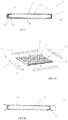
- la
figure 1 représente une vue en coupe d'un panneau amovible selon l'invention ; - les
figures 2A à 2G représente une illustration schématique des étapes de réalisation du panneau amovible de lafigure 1 .
- the
figure 1 shows a sectional view of a removable panel according to the invention; - them
figures 2A to 2G represents a schematic illustration of the stages of production of the removable panel of thefigure 1 .
En relation avec la
Le panneau amovible 1, de forme sensiblement parallélépipédique, comporte un corps de panneau 2 pourvu d'un revêtement de protection 4.The removable panel 1, of substantially parallelepipedic shape, comprises a panel body 2 provided with a protective coating 4.
Le corps de panneau 2 comporte une face inférieure 20 et une face supérieure 21 située du côté opposée de la face inférieure 20, lesdites faces étant délimitées par un bord périphérique 22 formé de quatre chants 220.The panel body 2 has a lower face 20 and an upper face 21 located on the opposite side of the lower face 20, said faces being delimited by a peripheral edge 22 formed by four edges 220.
Selon l'invention, le corps de panneau 2 comporte des profilés d'habillage 3 disposés le long du bord périphérique 22.According to the invention, the panel body 2 comprises trim sections 3 arranged along the peripheral edge 22.
Chaque profilé présente une section transversale en forme générale en U. Lorsque le profilé d'habillage est fixé sur le corps de panneau 2, l'âme 30 du U est en contact avec le chant 220 du bord périphérique 22 tandis que les branches 31, 32 du U s'étendant depuis les extrémités de l'âme 30 sont en contact avec les faces inférieure et supérieure 20, 21 du corps de panneau 2.Each profile has a generally U-shaped cross-section. When the covering profile is fixed to the panel body 2, the core 30 of the U is in contact with the edge 220 of the peripheral edge 22 while the branches 31, 32 of the U extending from the ends of the core 30 are in contact with the lower and upper faces 20, 21 of the panel body 2.
Chaque profilé d'habillage 3 peut être fixé sur le corps de panneau 2 par tous moyens et techniques appropriés connus de l'homme du métier. Ainsi, chaque profilé d'habillage 3 pourra par exemple être monté en force, collé, cloué ou encore vissé sur le panneau amovible.Each trim profile 3 can be fixed to the panel body 2 by any appropriate means and techniques known to those skilled in the art. Thus, each trim profile 3 can for example be mounted by force, glued, nailed or even screwed onto the removable panel.
Dans le mode réalisation décrit, le corps de panneau 2 est pourvu de quatre profilés d'habillage 3, chaque profilé étant monté sur un chant 220 du bord périphérique 20 pour former un cadre fermé fixé le long de la totalité du bord périphérique. Il est bien entendu évident que l'invention ne se limite pas à une telle configuration et qu'il peut être prévu un panneau amovible sans profilé d'habillage ou bien seulement deux profilés d'habillage 3 situés le long de deux chants opposés du bord périphérique.In the embodiment described, the panel body 2 is provided with four trim profiles 3, each profile being mounted on an edge 220 of the peripheral edge 20 to form a closed frame fixed along the entire peripheral edge. It is of course obvious that the invention is not limited to such a configuration and that it can be provided a removable panel without covering profile or even only two covering profiles 3 located along two opposite edges of the edge peripheral.
Le revêtement de protection 4 selon l'invention est formé par une enveloppe tubulaire 40 de matériau souple présentant une surface prédéterminée supérieure à la superficie du corps du panneau 20 à recouvrir en totalité. L'enveloppe 40 forme ainsi le revêtement de protection pour chacune des faces 20 21 du corps de panneau 2.The protective coating 4 according to the invention is formed by a tubular casing 40 of flexible material having a predetermined surface greater than the area of the body of the panel 20 to be completely covered. The envelope 40 thus forms the protective coating for each of the faces 20 21 of the panel body 2.
Avantageusement, l'enveloppe 40 est extensible et est réalisée de préférence à partir de feuille en matériau polymère tel que le polychlorure de vinyle. Le matériau de l'enveloppe pourra être également choisi en fonction des propriétés spécifiques souhaitées pour le faux plafond auquel le panneau amovible 1 est destiné, comme par exemple la résistance au feu, l'étanchéité à l'air, aux poussières et à l'humidité, la facilité d'entretien les performances acoustiques, etc.Advantageously, the envelope 40 is extensible and is preferably made from a sheet of polymeric material such as polyvinyl chloride. The envelope material may also be chosen according to the specific properties desired for the false ceiling for which the removable panel 1 is intended, such as for example fire resistance, air tightness, dust and humidity, ease of maintenance, acoustic performance, etc.
Du fait de la présence du cadre formé par les profilés d'habillage 3 et des dimensions du revêtement de protection 4, l'enveloppe 40, lorsqu'elle est placée sur le corps de panneau 2, n'est pas en contact direct avec les faces inférieure 20 et supérieur 21 du corps de panneau 2, de sorte que les aspérités et autres défauts de relief des faces 20, 21 de ce dernier ne sont pas visibles. On comprend bien en effet que si l'enveloppe 40 était posée directement sur le corps du panneau 20, les aspérités apparaîtraient toujours après la mise en place de l'enveloppe, cette dernière épousant les formes et donc tout relief présent sur la surface du corps du panneau 20.Due to the presence of the frame formed by the covering sections 3 and the dimensions of the protective covering 4, the envelope 40, when it is placed on the panel body 2, is not in direct contact with the lower 20 and upper 21 faces of the panel body 2, so that the roughness and other relief defects of the faces 20, 21 of the latter are not visible. It is indeed understood that if the envelope 40 were placed directly on the body of the panel 20, the roughness would always appear after the installation of the envelope, the latter marrying the shapes and therefore any relief present on the surface of the body. of panel 20.
Comme on le verra plus loin, l'enveloppe 40 est fixée avantageusement sur le corps de panneau 2, et plus particulièrement sur les profilés d'habillage 3 au moyen d'adhésifs.As will be seen below, the casing 40 is advantageously fixed to the panel body 2, and more particularly to the trim profiles 3 by means of adhesives.
Les étapes de réalisation du panneau amovible selon l'invention vont être à présent décrites. Elles sont illustrées sur les
Préalablement, il convient de préparer le corps de panneau 2 en l'équipant de profilés d'habillage 3 (
On entend par « profilés d'habillage dits latéraux », les profilés s'étendant parallèlement à la direction d'insertion du corps de panneau 2 dans l'enveloppe 40 et par « profilés d'habillage dits avant et arrière », les profilés s'étendant perpendiculairement à la direction d'insertion du corps de panneau dans l'enveloppe 40, le profilé d'habillage avant correspondant au profilé situé au niveau de l'ouverture de passage ménagée dans l'enveloppe 40, tandis que le profilé d'habillage arrière correspondant au profilé opposé au profilé d'habillage avant.The term "so-called side covering profiles" means the profiles extending parallel to the direction of insertion of the panel body 2 into the casing 40 and the term "so-called front and rear covering profiles", the profiles s extending perpendicularly to the direction of insertion of the panel body into the casing 40, the front trim profile corresponding to the profile located at the level of the passage opening made in the casing 40, while the profile of rear trim corresponding to the profile opposite the front trim profile.
Une fois les profilés d'habillage fixés sur le corps de panneau 2, ce dernier est inséré dans l'enveloppe tubulaire souple 40 laquelle présente une ouverture d'entrée 41 prévue à cet effet (
Une fois le corps de panneau 2 inséré dans l'enveloppe 40, une première couche d'adhésif 5 est appliquée sur tout ou partie de l'âme 30 du profilé d'habillage 3 faisant face à l'ouverture d'entrée 41 (profilé d'habillage avant) (
L'un des volets 42 de l'enveloppe 40 est ensuite rabattu sur l'âme 30 du profilé d'habillage 3 avant pour y être fixé. Lors de cette opération, il sera pris soin de tirer sur le volet 42, avant sa fixation sur le profilé 3 encollé, afin de mettre sous tension la partie 420 de l'enveloppe 40 s'étendant entre les deux profilés d'habillage 3 avant et arrière.One of the flaps 42 of the casing 40 is then folded over the core 30 of the trim section 3 before to be fixed there. During this operation, care will be taken to pull on the flap 42, before its attachment to the glued section 3, in order to tension the part 420 of the envelope 40 extending between the two trim sections 3 before and back.
La partie du volet excédentaire 422, c'est-à-dire la partie non collée s'étendant au delà du panneau (partie également appelée partie libre) est ensuite découpée (opération de découpe illustrée sur la
Une deuxième couche d'adhésif 6 est ensuite à nouveau appliquée sur l'âme 30 du profilé d'habillage 3 sur laquelle est fixé le premier volet 42 de l'enveloppe 40 (
Le deuxième volet 44 est ensuite rabattu, comme le premier volet 42, sur l'âme 30 du profilé encollée, pour y être fixé (
Dans l'exemple qui vient d'être décrit, l'enveloppe 40 est collée directement sur l'un des profilés d'habillage 3. Selon une variante de réalisation, il peut être prévu que les volets 42, 44 de l'enveloppe soient solidarisés directement entre eux. De même, il est évident que l'invention ne se limite pas aux moyens de fixation précédemment décrits, étant entendu que tout autre moyen et technique appropriés connus de l'homme du métier peuvent être mis en œuvre pour fixer l'enveloppe 40 sur le corps de panneau 2 sans sortir du cadre de l'invention.In the example which has just been described, the envelope 40 is glued directly to one of the covering sections 3. According to a variant embodiment, it may be provided that the flaps 42, 44 of the envelope are connected directly to each other. Similarly, it is obvious that the invention is not limited to the attachment means described above, it being understood that any other appropriate means and technique known to those skilled in the art can be implemented to attach the casing 40 to the panel body 2 without departing from the scope of the invention.
S'agissant de la réalisation de l'enveloppe tubulaire 40, cette dernière est avantageusement réalisée à partir d'une bande de matériau souple, de préférence une toile, repliée pour former deux volets superposés l'un par rapport à l'autre, les bords de chaque volet adjacents à la ligne de pliure et disposés en vis-à-vis étant solidarisés l'un à l'autre.With regard to the production of the tubular envelope 40, the latter is advantageously made from a strip of flexible material, preferably a fabric, folded to form two flaps superimposed with respect to each other, the edges of each flap adjacent to the fold line and arranged facing each other being secured to one another.
Selon une variante de réalisation, il peut être prévu de réaliser l'enveloppe tubulaire 40 à partir de deux feuilles de matériau souple distinctes, de préférence deux feuille de toile, disposées superposées l'une par rapport à l'autre, deux des bords opposés d'une feuille étant solidarisés avec les bords disposés en vis-à-vis de l'autre feuille. Préférentiellement, un troisième bord de l'une des feuilles est solidarisé avec le bord latéral disposé en vis-à-vis de l'autre feuille. L'enveloppe ainsi formée constitue un sac, une telle configuration ayant pour avantage de permettre de recouvrir rapidement et facilement le corps de panneau 2 dans sa totalité d'un revêtement de protection.According to a variant embodiment, provision may be made to produce the tubular casing 40 from two separate sheets of flexible material, preferably two sheets of fabric, arranged superimposed with respect to each other, two of the opposite edges of a sheet being secured to the edges arranged opposite the other sheet. Preferably, a third edge of one of the sheets is secured to the side edge arranged opposite the other sheet. The envelope thus formed constitutes a bag, such a configuration having the advantage of allowing the panel body 2 to be covered quickly and easily in its entirety with a protective coating.
Avantageusement, l'enveloppe est réalisée en une matière extansible. Cela permet ainsi de faciliter l'insertion du corps de panneau 2 dans l'enveloppe 40 tout en offrant une toile tendue autour du corps de panneau 2 une fois l'enveloppe 40 en place.Advantageously, the envelope is made of an expandable material. This thus makes it possible to facilitate the insertion of the panel body 2 into the casing 40 while providing a canvas stretched around the panel body 2 once the casing 40 is in place.
L'invention est décrite dans ce qui précède à titre d'exemple. Il est entendu que l'homme du métier est à même de réaliser différentes variantes de réalisation de l'invention sans pour autant sortir du cadre des revendications.The invention is described in the foregoing by way of example. It is understood that a person skilled in the art is able to produce different variant embodiments of the invention without departing from the scope of the claims.
Claims (9)
- Method for producing a restorable removable panel (1) for a false wall, the panel comprising a panel body (2) having a lower face (20) and an upper face (21) which are delimited by a peripheral edge (22), the method comprising a step consisting of simultaneously covering the two faces (20, 21) of the panel body (2) with a protective covering (4) by inserting the panel body (2) into a tubular casing (40), at least one of the ends of which delimits an entry opening, the tubular casing which is made of a flexible material and has a predetermined surface area greater than the surface area of the panel body (2) to be completely covered forming the protective covering (4) of each of the faces (20, 22) of the panel body (2), said method being characterized in that the panel body (2) is fitted beforehand with at least two trim profiles (3) placed respectively along two opposing regions of the peripheral edge (22) of said body.
- Method for producing a removable panel (1) according to claim 1, characterized in that it also comprises the steps consisting of:- placing the panel body (2) inside the tubular casing (40), one of the trim profiles (3) facing the entry opening (41) of the casing (40),- closing the entry opening (41) of the casing (40) at said trim profile (3) after having placed the casing between the two trim profiles under tension, and- cutting off, if necessary, the excess of the casing (40) that extends beyond the trim profile (3).
- Method for producing a removable panel (1) according to claim 2, characterized in that the step of closing the entry opening (41) of the casing (40) consists of:- applying a first layer of adhesive (5) onto all or part of the trim profile (3) facing the entry opening (41),- turning down one of the flaps (42) of the casing (40) over the trim profile (3) provided with the first layer of adhesive (5) after having placed the part of the casing extending between the two trim profiles under tension,- applying a second layer of adhesive (6) onto all or part of the trim profile (3) facing the entry opening (41),- turning down the other flap (44) of the casing (40) over said trim profile (3) provided with the second layer of adhesive (6) after having placed the part of the casing extending between the two trim profiles under tension, and- cutting off, if necessary, the excess part (422, 442) of the casing (40).
- Method for producing a removable panel (1) according to claim 3, characterized in that, prior to the step of securing the second flap (44), the excess part (421) of the first flap (42) is cut off.
- Method for producing a removable panel (1) according to any one of claims 1 to 4, characterized in that the tubular casing (40) is made from a strip of flexible fabric folded over a fold line to form two flaps placed one on top of the other, the edges of each flap that are adjacent to the fold line and arranged opposite one another being secured to one another.
- Method for producing a removable panel (1) according to any one of claims 1 to 4, characterized in that the tubular casing (40) is made from two separate sheets of flexible fabric which are arranged so as to be placed one on top of the other, two of the opposing edges of a sheet being secured to the edges of the other sheet that are arranged opposite.
- Method for producing a removable panel (1) according to claim 6, characterized in that a third edge of one of the sheets is secured to the lateral edge of the other sheet that is arranged opposite, the casing (40) forming a bag for receiving the panel body.
- Restorable removable panel (1) for a false wall, obtained according to the method of production according to any one of the preceding claims.
- Removable panel (1) according to claim 8, characterized in that the tubular casing (40) is extendable.
Applications Claiming Priority (2)
| Application Number | Priority Date | Filing Date | Title |
|---|---|---|---|
| FR1257216A FR2993909B1 (en) | 2012-07-25 | 2012-07-25 | REMOVABLE REMOVABLE PANEL AND METHOD FOR PRODUCING SUCH PANEL |
| PCT/FR2013/051790 WO2014016520A1 (en) | 2012-07-25 | 2013-07-25 | Removable panel that can be renovated and method for creating such a panel |
Publications (2)
| Publication Number | Publication Date |
|---|---|
| EP2877648A1 EP2877648A1 (en) | 2015-06-03 |
| EP2877648B1 true EP2877648B1 (en) | 2022-10-26 |
Family
ID=47424993
Family Applications (1)
| Application Number | Title | Priority Date | Filing Date |
|---|---|---|---|
| EP13758909.9A Active EP2877648B1 (en) | 2012-07-25 | 2013-07-25 | Removable panel that can be renovated and method for creating such a panel |
Country Status (5)
| Country | Link |
|---|---|
| EP (1) | EP2877648B1 (en) |
| ES (1) | ES2934107T3 (en) |
| FR (1) | FR2993909B1 (en) |
| HK (1) | HK1206087A1 (en) |
| WO (1) | WO2014016520A1 (en) |
Family Cites Families (5)
| Publication number | Priority date | Publication date | Assignee | Title |
|---|---|---|---|---|
| US2113068A (en) * | 1937-02-01 | 1938-04-05 | American Houses Inc | Insulation |
| US3020183A (en) * | 1959-05-13 | 1962-02-06 | Calvaresi Archie | Protective insulating mat |
| GB891914A (en) * | 1959-09-29 | 1962-03-21 | Michael Bennett | Improved panel construction |
| US5009043A (en) * | 1990-07-12 | 1991-04-23 | Herman Miller, Inc. | Acoustic panel |
| DE102007009250A1 (en) * | 2007-02-22 | 2008-08-28 | Rudolf Henrichsmeyer Formaplan Gmbh & Co. Kg | Furniture component and method for its production |
-
2012
- 2012-07-25 FR FR1257216A patent/FR2993909B1/en active Active
-
2013
- 2013-07-25 EP EP13758909.9A patent/EP2877648B1/en active Active
- 2013-07-25 ES ES13758909T patent/ES2934107T3/en active Active
- 2013-07-25 WO PCT/FR2013/051790 patent/WO2014016520A1/en active Application Filing
-
2015
- 2015-07-15 HK HK15106741.2A patent/HK1206087A1/en unknown
Also Published As
| Publication number | Publication date |
|---|---|
| FR2993909A1 (en) | 2014-01-31 |
| ES2934107T3 (en) | 2023-02-16 |
| FR2993909B1 (en) | 2015-01-16 |
| EP2877648A1 (en) | 2015-06-03 |
| WO2014016520A1 (en) | 2014-01-30 |
| HK1206087A1 (en) | 2015-12-31 |
Similar Documents
| Publication | Publication Date | Title |
|---|---|---|
| EP2766538B1 (en) | Device for re-cladding a removable panel | |
| EP2494120B1 (en) | Fixing system for a false wall having guided clamping | |
| CA2314543C (en) | Container with reinforced closure | |
| FR2775491A1 (en) | FINISHING PROFILE DEVICE FOR MOUNTING WALL OR CEILING COVERING PANELS | |
| EP1546276A1 (en) | Automated method of preparing and producing pull tabs and a protective film and an extruded section having a protective film comprising pull tabs of said type | |
| EP2877648B1 (en) | Removable panel that can be renovated and method for creating such a panel | |
| EP3463954B1 (en) | Window with profiled sealing with trim and method for manufacturing said window | |
| EP2369092B1 (en) | One-piece border element for glueing | |
| EP2157360A1 (en) | Box with raised anti-dust pattern | |
| WO2018146186A1 (en) | Method for mounting a stretched flexible covering on a mounting frame and mounting frame for implementing said method | |
| EP2369095B1 (en) | System for skirting board | |
| EP2900884A1 (en) | Mirror wall tile and method for manufacturing such a tile | |
| EP2369091A1 (en) | Adhesive skirting board | |
| EP2050896A1 (en) | Flooring | |
| FR2539336A1 (en) | Painting booth made from modular panels | |
| FR2672914A1 (en) | Bridging device | |
| EP2770132B1 (en) | Box frame including a sealing means and box including such a frame | |
| EP0327474B1 (en) | Edging strip and method of making it | |
| EP2175086A1 (en) | Accessory for bar with slide threshold | |
| FR2728001A1 (en) | Method of erecting panel and fixing mural to it | |
| EP1522672A1 (en) | Guiding device for a screen of a blind, profil with such a guiding device and a corresponding roller blind | |
| FR3108892A1 (en) | Folding box formed by an assembly of marouflaged cardboard sheets | |
| FR2918406A1 (en) | Door bottom insulating device for weather stripping e.g. lift-up door, has tab fixed at door, and insulation band presents elastically deformable insulating material on surface opposite to bottom door | |
| EP3714114A1 (en) | Profiled cladding panel comprising a seal, and method for producing such a panel | |
| FR3025989A1 (en) | FOLDING BOTTOM FOR EQUIPPING A FURNITURE |
Legal Events
| Date | Code | Title | Description |
|---|---|---|---|
| PUAI | Public reference made under article 153(3) epc to a published international application that has entered the european phase |
Free format text: ORIGINAL CODE: 0009012 |
|
| 17P | Request for examination filed |
Effective date: 20141217 |
|
| AK | Designated contracting states |
Kind code of ref document: A1 Designated state(s): AL AT BE BG CH CY CZ DE DK EE ES FI FR GB GR HR HU IE IS IT LI LT LU LV MC MK MT NL NO PL PT RO RS SE SI SK SM TR |
|
| AX | Request for extension of the european patent |
Extension state: BA ME |
|
| DAX | Request for extension of the european patent (deleted) | ||
| REG | Reference to a national code |
Ref country code: HK Ref legal event code: DE Ref document number: 1206087 Country of ref document: HK |
|
| STAA | Information on the status of an ep patent application or granted ep patent |
Free format text: STATUS: EXAMINATION IS IN PROGRESS |
|
| 17Q | First examination report despatched |
Effective date: 20190611 |
|
| STAA | Information on the status of an ep patent application or granted ep patent |
Free format text: STATUS: EXAMINATION IS IN PROGRESS |
|
| STAA | Information on the status of an ep patent application or granted ep patent |
Free format text: STATUS: EXAMINATION IS IN PROGRESS |
|
| GRAP | Despatch of communication of intention to grant a patent |
Free format text: ORIGINAL CODE: EPIDOSNIGR1 |
|
| STAA | Information on the status of an ep patent application or granted ep patent |
Free format text: STATUS: GRANT OF PATENT IS INTENDED |
|
| INTG | Intention to grant announced |
Effective date: 20220518 |
|
| GRAS | Grant fee paid |
Free format text: ORIGINAL CODE: EPIDOSNIGR3 |
|
| GRAA | (expected) grant |
Free format text: ORIGINAL CODE: 0009210 |
|
| STAA | Information on the status of an ep patent application or granted ep patent |
Free format text: STATUS: THE PATENT HAS BEEN GRANTED |
|
| AK | Designated contracting states |
Kind code of ref document: B1 Designated state(s): AL AT BE BG CH CY CZ DE DK EE ES FI FR GB GR HR HU IE IS IT LI LT LU LV MC MK MT NL NO PL PT RO RS SE SI SK SM TR |
|
| REG | Reference to a national code |
Ref country code: GB Ref legal event code: FG4D Free format text: NOT ENGLISH |
|
| RIN1 | Information on inventor provided before grant (corrected) |
Inventor name: SCHERRER, JEAN-MARC |
|
| REG | Reference to a national code |
Ref country code: CH Ref legal event code: EP |
|
| REG | Reference to a national code |
Ref country code: DE Ref legal event code: R096 Ref document number: 602013082747 Country of ref document: DE |
|
| REG | Reference to a national code |
Ref country code: AT Ref legal event code: REF Ref document number: 1527125 Country of ref document: AT Kind code of ref document: T Effective date: 20221115 |
|
| REG | Reference to a national code |
Ref country code: IE Ref legal event code: FG4D Free format text: LANGUAGE OF EP DOCUMENT: FRENCH |
|
| REG | Reference to a national code |
Ref country code: LT Ref legal event code: MG9D |
|
| REG | Reference to a national code |
Ref country code: ES Ref legal event code: FG2A Ref document number: 2934107 Country of ref document: ES Kind code of ref document: T3 Effective date: 20230216 |
|
| REG | Reference to a national code |
Ref country code: NL Ref legal event code: MP Effective date: 20221026 |
|
| REG | Reference to a national code |
Ref country code: AT Ref legal event code: MK05 Ref document number: 1527125 Country of ref document: AT Kind code of ref document: T Effective date: 20221026 |
|
| PG25 | Lapsed in a contracting state [announced via postgrant information from national office to epo] |
Ref country code: NL Free format text: LAPSE BECAUSE OF FAILURE TO SUBMIT A TRANSLATION OF THE DESCRIPTION OR TO PAY THE FEE WITHIN THE PRESCRIBED TIME-LIMIT Effective date: 20221026 |
|
| PG25 | Lapsed in a contracting state [announced via postgrant information from national office to epo] |
Ref country code: SE Free format text: LAPSE BECAUSE OF FAILURE TO SUBMIT A TRANSLATION OF THE DESCRIPTION OR TO PAY THE FEE WITHIN THE PRESCRIBED TIME-LIMIT Effective date: 20221026 Ref country code: PT Free format text: LAPSE BECAUSE OF FAILURE TO SUBMIT A TRANSLATION OF THE DESCRIPTION OR TO PAY THE FEE WITHIN THE PRESCRIBED TIME-LIMIT Effective date: 20230227 Ref country code: NO Free format text: LAPSE BECAUSE OF FAILURE TO SUBMIT A TRANSLATION OF THE DESCRIPTION OR TO PAY THE FEE WITHIN THE PRESCRIBED TIME-LIMIT Effective date: 20230126 Ref country code: LT Free format text: LAPSE BECAUSE OF FAILURE TO SUBMIT A TRANSLATION OF THE DESCRIPTION OR TO PAY THE FEE WITHIN THE PRESCRIBED TIME-LIMIT Effective date: 20221026 Ref country code: FI Free format text: LAPSE BECAUSE OF FAILURE TO SUBMIT A TRANSLATION OF THE DESCRIPTION OR TO PAY THE FEE WITHIN THE PRESCRIBED TIME-LIMIT Effective date: 20221026 Ref country code: AT Free format text: LAPSE BECAUSE OF FAILURE TO SUBMIT A TRANSLATION OF THE DESCRIPTION OR TO PAY THE FEE WITHIN THE PRESCRIBED TIME-LIMIT Effective date: 20221026 |
|
| PG25 | Lapsed in a contracting state [announced via postgrant information from national office to epo] |
Ref country code: RS Free format text: LAPSE BECAUSE OF FAILURE TO SUBMIT A TRANSLATION OF THE DESCRIPTION OR TO PAY THE FEE WITHIN THE PRESCRIBED TIME-LIMIT Effective date: 20221026 Ref country code: PL Free format text: LAPSE BECAUSE OF FAILURE TO SUBMIT A TRANSLATION OF THE DESCRIPTION OR TO PAY THE FEE WITHIN THE PRESCRIBED TIME-LIMIT Effective date: 20221026 Ref country code: LV Free format text: LAPSE BECAUSE OF FAILURE TO SUBMIT A TRANSLATION OF THE DESCRIPTION OR TO PAY THE FEE WITHIN THE PRESCRIBED TIME-LIMIT Effective date: 20221026 Ref country code: IS Free format text: LAPSE BECAUSE OF FAILURE TO SUBMIT A TRANSLATION OF THE DESCRIPTION OR TO PAY THE FEE WITHIN THE PRESCRIBED TIME-LIMIT Effective date: 20230226 Ref country code: HR Free format text: LAPSE BECAUSE OF FAILURE TO SUBMIT A TRANSLATION OF THE DESCRIPTION OR TO PAY THE FEE WITHIN THE PRESCRIBED TIME-LIMIT Effective date: 20221026 Ref country code: GR Free format text: LAPSE BECAUSE OF FAILURE TO SUBMIT A TRANSLATION OF THE DESCRIPTION OR TO PAY THE FEE WITHIN THE PRESCRIBED TIME-LIMIT Effective date: 20230127 |
|
| REG | Reference to a national code |
Ref country code: DE Ref legal event code: R097 Ref document number: 602013082747 Country of ref document: DE |
|
| PG25 | Lapsed in a contracting state [announced via postgrant information from national office to epo] |
Ref country code: SM Free format text: LAPSE BECAUSE OF FAILURE TO SUBMIT A TRANSLATION OF THE DESCRIPTION OR TO PAY THE FEE WITHIN THE PRESCRIBED TIME-LIMIT Effective date: 20221026 Ref country code: RO Free format text: LAPSE BECAUSE OF FAILURE TO SUBMIT A TRANSLATION OF THE DESCRIPTION OR TO PAY THE FEE WITHIN THE PRESCRIBED TIME-LIMIT Effective date: 20221026 Ref country code: EE Free format text: LAPSE BECAUSE OF FAILURE TO SUBMIT A TRANSLATION OF THE DESCRIPTION OR TO PAY THE FEE WITHIN THE PRESCRIBED TIME-LIMIT Effective date: 20221026 Ref country code: DK Free format text: LAPSE BECAUSE OF FAILURE TO SUBMIT A TRANSLATION OF THE DESCRIPTION OR TO PAY THE FEE WITHIN THE PRESCRIBED TIME-LIMIT Effective date: 20221026 Ref country code: CZ Free format text: LAPSE BECAUSE OF FAILURE TO SUBMIT A TRANSLATION OF THE DESCRIPTION OR TO PAY THE FEE WITHIN THE PRESCRIBED TIME-LIMIT Effective date: 20221026 |
|
| PGFP | Annual fee paid to national office [announced via postgrant information from national office to epo] |
Ref country code: IT Payment date: 20230620 Year of fee payment: 11 Ref country code: FR Payment date: 20230621 Year of fee payment: 11 |
|
| PG25 | Lapsed in a contracting state [announced via postgrant information from national office to epo] |
Ref country code: SK Free format text: LAPSE BECAUSE OF FAILURE TO SUBMIT A TRANSLATION OF THE DESCRIPTION OR TO PAY THE FEE WITHIN THE PRESCRIBED TIME-LIMIT Effective date: 20221026 Ref country code: AL Free format text: LAPSE BECAUSE OF FAILURE TO SUBMIT A TRANSLATION OF THE DESCRIPTION OR TO PAY THE FEE WITHIN THE PRESCRIBED TIME-LIMIT Effective date: 20221026 |
|
| PGFP | Annual fee paid to national office [announced via postgrant information from national office to epo] |
Ref country code: LU Payment date: 20230620 Year of fee payment: 11 |
|
| PLBE | No opposition filed within time limit |
Free format text: ORIGINAL CODE: 0009261 |
|
| STAA | Information on the status of an ep patent application or granted ep patent |
Free format text: STATUS: NO OPPOSITION FILED WITHIN TIME LIMIT |
|
| PGFP | Annual fee paid to national office [announced via postgrant information from national office to epo] |
Ref country code: BE Payment date: 20230622 Year of fee payment: 11 |
|
| 26N | No opposition filed |
Effective date: 20230727 |
|
| PGFP | Annual fee paid to national office [announced via postgrant information from national office to epo] |
Ref country code: GB Payment date: 20230620 Year of fee payment: 11 Ref country code: ES Payment date: 20230801 Year of fee payment: 11 |
|
| PG25 | Lapsed in a contracting state [announced via postgrant information from national office to epo] |
Ref country code: SI Free format text: LAPSE BECAUSE OF FAILURE TO SUBMIT A TRANSLATION OF THE DESCRIPTION OR TO PAY THE FEE WITHIN THE PRESCRIBED TIME-LIMIT Effective date: 20221026 |
|
| PGFP | Annual fee paid to national office [announced via postgrant information from national office to epo] |
Ref country code: DE Payment date: 20230620 Year of fee payment: 11 |
|
| PG25 | Lapsed in a contracting state [announced via postgrant information from national office to epo] |
Ref country code: MC Free format text: LAPSE BECAUSE OF FAILURE TO SUBMIT A TRANSLATION OF THE DESCRIPTION OR TO PAY THE FEE WITHIN THE PRESCRIBED TIME-LIMIT Effective date: 20221026 |
|
| PG25 | Lapsed in a contracting state [announced via postgrant information from national office to epo] |
Ref country code: MC Free format text: LAPSE BECAUSE OF FAILURE TO SUBMIT A TRANSLATION OF THE DESCRIPTION OR TO PAY THE FEE WITHIN THE PRESCRIBED TIME-LIMIT Effective date: 20221026 |
|
| REG | Reference to a national code |
Ref country code: CH Ref legal event code: PL |