EP2877283B1 - Système de raccordement d'un embout de pipetage à un conduit de pipetage d'un dispositif de pipetage - Google Patents
Système de raccordement d'un embout de pipetage à un conduit de pipetage d'un dispositif de pipetage Download PDFInfo
- Publication number
- EP2877283B1 EP2877283B1 EP13740273.1A EP13740273A EP2877283B1 EP 2877283 B1 EP2877283 B1 EP 2877283B1 EP 13740273 A EP13740273 A EP 13740273A EP 2877283 B1 EP2877283 B1 EP 2877283B1
- Authority
- EP
- European Patent Office
- Prior art keywords
- coupling
- pipetting
- coupling formation
- formation
- section
- Prior art date
- Legal status (The legal status is an assumption and is not a legal conclusion. Google has not performed a legal analysis and makes no representation as to the accuracy of the status listed.)
- Active
Links
- 238000010168 coupling process Methods 0.000 title claims description 354
- 230000008878 coupling Effects 0.000 title claims description 352
- 238000005859 coupling reaction Methods 0.000 title claims description 352
- 230000015572 biosynthetic process Effects 0.000 title claims description 159
- 230000000712 assembly Effects 0.000 claims description 17
- 238000000429 assembly Methods 0.000 claims description 17
- 238000005755 formation reaction Methods 0.000 description 122
- 238000012549 training Methods 0.000 description 24
- 238000007789 sealing Methods 0.000 description 19
- 239000000463 material Substances 0.000 description 12
- 239000012530 fluid Substances 0.000 description 8
- 238000004891 communication Methods 0.000 description 6
- 230000006835 compression Effects 0.000 description 4
- 238000007906 compression Methods 0.000 description 4
- 239000007788 liquid Substances 0.000 description 4
- 238000011161 development Methods 0.000 description 3
- 238000001746 injection moulding Methods 0.000 description 3
- 238000004519 manufacturing process Methods 0.000 description 3
- 238000000034 method Methods 0.000 description 3
- 238000013461 design Methods 0.000 description 2
- 238000002347 injection Methods 0.000 description 2
- 239000007924 injection Substances 0.000 description 2
- 238000003780 insertion Methods 0.000 description 2
- 230000037431 insertion Effects 0.000 description 2
- 230000002093 peripheral effect Effects 0.000 description 2
- 230000005540 biological transmission Effects 0.000 description 1
- 230000001808 coupling effect Effects 0.000 description 1
- 238000006073 displacement reaction Methods 0.000 description 1
- 230000000694 effects Effects 0.000 description 1
- 229920001971 elastomer Polymers 0.000 description 1
- 239000000806 elastomer Substances 0.000 description 1
- 238000003032 molecular docking Methods 0.000 description 1
- 238000012545 processing Methods 0.000 description 1
- 239000000243 solution Substances 0.000 description 1
- 210000002023 somite Anatomy 0.000 description 1
Images


Classifications
-
- F—MECHANICAL ENGINEERING; LIGHTING; HEATING; WEAPONS; BLASTING
- F16—ENGINEERING ELEMENTS AND UNITS; GENERAL MEASURES FOR PRODUCING AND MAINTAINING EFFECTIVE FUNCTIONING OF MACHINES OR INSTALLATIONS; THERMAL INSULATION IN GENERAL
- F16L—PIPES; JOINTS OR FITTINGS FOR PIPES; SUPPORTS FOR PIPES, CABLES OR PROTECTIVE TUBING; MEANS FOR THERMAL INSULATION IN GENERAL
- F16L37/00—Couplings of the quick-acting type
- F16L37/08—Couplings of the quick-acting type in which the connection between abutting or axially overlapping ends is maintained by locking members
- F16L37/084—Couplings of the quick-acting type in which the connection between abutting or axially overlapping ends is maintained by locking members combined with automatic locking
- F16L37/086—Couplings of the quick-acting type in which the connection between abutting or axially overlapping ends is maintained by locking members combined with automatic locking by means of latching members pushed radially by spring-like elements
-
- B—PERFORMING OPERATIONS; TRANSPORTING
- B01—PHYSICAL OR CHEMICAL PROCESSES OR APPARATUS IN GENERAL
- B01L—CHEMICAL OR PHYSICAL LABORATORY APPARATUS FOR GENERAL USE
- B01L3/00—Containers or dishes for laboratory use, e.g. laboratory glassware; Droppers
- B01L3/02—Burettes; Pipettes
- B01L3/021—Pipettes, i.e. with only one conduit for withdrawing and redistributing liquids
- B01L3/0217—Pipettes, i.e. with only one conduit for withdrawing and redistributing liquids of the plunger pump type
- B01L3/0224—Pipettes, i.e. with only one conduit for withdrawing and redistributing liquids of the plunger pump type having mechanical means to set stroke length, e.g. movable stops
-
- B—PERFORMING OPERATIONS; TRANSPORTING
- B01—PHYSICAL OR CHEMICAL PROCESSES OR APPARATUS IN GENERAL
- B01L—CHEMICAL OR PHYSICAL LABORATORY APPARATUS FOR GENERAL USE
- B01L3/00—Containers or dishes for laboratory use, e.g. laboratory glassware; Droppers
- B01L3/02—Burettes; Pipettes
- B01L3/021—Pipettes, i.e. with only one conduit for withdrawing and redistributing liquids
-
- B—PERFORMING OPERATIONS; TRANSPORTING
- B01—PHYSICAL OR CHEMICAL PROCESSES OR APPARATUS IN GENERAL
- B01L—CHEMICAL OR PHYSICAL LABORATORY APPARATUS FOR GENERAL USE
- B01L3/00—Containers or dishes for laboratory use, e.g. laboratory glassware; Droppers
- B01L3/02—Burettes; Pipettes
- B01L3/0275—Interchangeable or disposable dispensing tips
- B01L3/0279—Interchangeable or disposable dispensing tips co-operating with positive ejection means
-
- F—MECHANICAL ENGINEERING; LIGHTING; HEATING; WEAPONS; BLASTING
- F16—ENGINEERING ELEMENTS AND UNITS; GENERAL MEASURES FOR PRODUCING AND MAINTAINING EFFECTIVE FUNCTIONING OF MACHINES OR INSTALLATIONS; THERMAL INSULATION IN GENERAL
- F16L—PIPES; JOINTS OR FITTINGS FOR PIPES; SUPPORTS FOR PIPES, CABLES OR PROTECTIVE TUBING; MEANS FOR THERMAL INSULATION IN GENERAL
- F16L21/00—Joints with sleeve or socket
- F16L21/02—Joints with sleeve or socket with elastic sealing rings between pipe and sleeve or between pipe and socket, e.g. with rolling or other prefabricated profiled rings
- F16L21/035—Joints with sleeve or socket with elastic sealing rings between pipe and sleeve or between pipe and socket, e.g. with rolling or other prefabricated profiled rings placed around the spigot end before connection
-
- F—MECHANICAL ENGINEERING; LIGHTING; HEATING; WEAPONS; BLASTING
- F16—ENGINEERING ELEMENTS AND UNITS; GENERAL MEASURES FOR PRODUCING AND MAINTAINING EFFECTIVE FUNCTIONING OF MACHINES OR INSTALLATIONS; THERMAL INSULATION IN GENERAL
- F16L—PIPES; JOINTS OR FITTINGS FOR PIPES; SUPPORTS FOR PIPES, CABLES OR PROTECTIVE TUBING; MEANS FOR THERMAL INSULATION IN GENERAL
- F16L21/00—Joints with sleeve or socket
- F16L21/08—Joints with sleeve or socket with additional locking means
-
- B—PERFORMING OPERATIONS; TRANSPORTING
- B01—PHYSICAL OR CHEMICAL PROCESSES OR APPARATUS IN GENERAL
- B01L—CHEMICAL OR PHYSICAL LABORATORY APPARATUS FOR GENERAL USE
- B01L2200/00—Solutions for specific problems relating to chemical or physical laboratory apparatus
- B01L2200/02—Adapting objects or devices to another
- B01L2200/023—Adapting objects or devices to another adapted for different sizes of tubes, tips or container
-
- F—MECHANICAL ENGINEERING; LIGHTING; HEATING; WEAPONS; BLASTING
- F16—ENGINEERING ELEMENTS AND UNITS; GENERAL MEASURES FOR PRODUCING AND MAINTAINING EFFECTIVE FUNCTIONING OF MACHINES OR INSTALLATIONS; THERMAL INSULATION IN GENERAL
- F16L—PIPES; JOINTS OR FITTINGS FOR PIPES; SUPPORTS FOR PIPES, CABLES OR PROTECTIVE TUBING; MEANS FOR THERMAL INSULATION IN GENERAL
- F16L2201/00—Special arrangements for pipe couplings
- F16L2201/40—Special arrangements for pipe couplings for special environments
- F16L2201/44—Special arrangements for pipe couplings for special environments sterile
Definitions
- the present invention relates to a coupling formation of a pipetting channel of a pipetting device for coupling a working device, such as a pipette tip or a laboratory device, laboratory tool and the like thereto.
- the coupling formation thereby surrounds a pipetting channel section which extends along a pipetting channel axis defining an axial direction, wherein the coupling formation further has at its free longitudinal end a pressure-communicating opening into which the pipetting channel section opens, and wherein the coupling formation surrounds the pipetting channel axis and mainly in the axial direction and in the circumferential direction around the Pipettierkanalachse extending, relative to the Pipettierkanalachse radially outer surface has a radially resilient coupling projection.
- Such coupling formations with a pipetting tip which can be coupled thereto as a working device are known, for example, from US Pat DE 199 17 375 A1 and the EP1862219A1 known.
- a pressure of a working fluid changed by a pressure-changing device such as a pump or a piston-cylinder arrangement, in the pipetting channel for aspiration and / or dispensing of a dosing fluid can be transmitted through a pipetting opening of a coupled pipetting tip into the dosing space surrounding the pipetting tip.
- the ferrule is movable along the Pipettierkanalachse relative to the support of the O-ring, so that the O-ring between the ferrule and support is crushable.
- the O-ring surrounds the Pipettierkanalachse. It comes then, if the ferrule is moved to squeeze the O-ring in the axial direction on the support, first to a primary axial compression of the O-ring and, consequently, to a radial expansion of the O-ring - always based on the Pipettierkanalachse -, so that the O-ring after squeezing a larger outer diameter than in mechanically unloaded condition. In the crimped state, the radially expanded O-ring provides a coupling protrusion at its radially outer edge.
- the position and shape of the circumferential in the coupling portion of the working holding recess is selected such that the radially expanded O-ring of the coupling formation on an inclined surface portion of the holding recess comes to rest such that the coupling portion of the working device, in particular the pipette tip, through the radial expanded O-ring not only positively held at the coupling formation, but in a Aufsteckides, in which the coupling portion is plugged onto the coupling formation for coupling to the pipetting device, is biased.
- the implement By trained separately from the ferrule and also axially movable relative to the support stripping sleeve, the implement can be stripped from the known coupling training and thus solved.
- the known coupling training has proven itself in competition and provides excellent results, in particular an excellent repeatable secure coupling of pipetting tips and other equipment at the coupling training.
- the coupling projection is substantially non-deformable, but provided radially displaceable on the coupling formation.
- a radially elastic spring arrangement is provided on the coupling formation.
- the coupling projection is always present and interacts with a spring arrangement which is elastic in the radial direction and thus with a spring arrangement designed to exert a force in the radial direction.
- This makes it possible to form the coupling projection in the manner of a latching projection on which a pipetting tip can be plugged, and which is driven by the force of the spring arrangement moves into a latching engagement position when plugged coupling portion of a working device.
- the pipetting tips and other working devices designed for coupling to coupling designs of the prior art can be structurally and unchanged coupled to the coupling formation according to the invention.
- the coupling projection of the coupling formation according to the invention it is only necessary for the coupling projection of the coupling formation according to the invention to be advantageous with respect to the coupling formation Stop surface, which with the corresponding counter-bearing surfaces of a coupled coupling portion of a working device, in particular a pipetting tip, of the same is in engagement engagement, a predetermined distance, usually axial distance having.
- any working device can be coupled to the pipetting device in the context of the present invention.
- Mainly is intended as a working device to a pipette tip, which allows in the coupled to the pipetting device aspiration and dispensing liquids by means of a pressure change of a different of the liquid to be dosed working fluid in a conventional manner.
- another laboratory device or a laboratory tool such as a carrying tool for transporting labware, can be coupled to a pipetting device as a working device.
- a support tool may for example be so-called "MTP plates”.
- These laboratory devices like the aforementioned pipetting tips, can also be coupled with the coupling recesses designed to be coupled to the coupling formation with the coupling formation presented here.
- the directions “axial,””radial,” and “circumferential” refer to directions relative to the pipetting channel axis. If a coupling state is mentioned, in which a working device, in particular a pipette tip, is coupled to the coupling formation according to the invention, then, unless otherwise stated, it should be assumed that the pipetting channel axis is aligned with a longitudinal axis of the pipetting tip or generally coincides with a longitudinal axis of a coupling portion of a working device.
- a passive locking of a coupling longitudinal end or a coupling portion of a pipette tip or generally a working device to the coupling formation according to the invention for coupling the same with the pipetting device can take place without further actuation of a separate device, such as the squeezing device known from the prior art, in that the coupling projection, which is initially unloaded from the outside, can be displaced against the elastic force of the spring arrangement by a radial force directed radially inwards onto the pipetting channel axis.
- the elastic force of the spring assembly biases the coupling projection radially outward.
- a coupling section of the working device in particular the pipetting tip, can thus be fitted radially on the outside of the coupling formation of the present invention and initially displace the coupling projection against the elastic force of the spring arrangement radially inward until the coupling projection Implement relative to the coupling formation reaches a position in which a form-fitting engagement with the coupling projection formed retaining recess in the coupling portion of the working device is located so that the elastic force of the spring assembly, the coupling projection for producing a latching engagement with the coupling portion of a working device radially outward into the Garrungsausinstituung relocated.
- the radial distance of the coupling projection from the Pipettierkanalachse in a free, uncoupled by a coupling portion of a working condition of the coupling formation can be greater than when a working device is coupled to the coupling formation, so that the spring arrangement in the case of a coupling of a working device, the coupling projection with elastic force can bias radially outward to the coupling portion of the implement towards.
- the coupling projection revolve around the pipetting channel axis.
- any spring arrangements can be used as the elastic force providing above-mentioned spring arrangement.
- a helical compression spring may be arranged with essentially the radial spring axis in the coupling formation relative to the pipetting channel axis.
- a plurality of such helical compression springs may be provided around the Pipettierkanalachse around to provide a circumferentially as uniform as possible elastic force can.
- This at least one helical compression spring in the case of several springs each spring, can bias a separately formed by the spring coupling projection, approximately on the model of a ball catch, radially outward.
- leaf springs are geometrically simple components, which can be provided with little manufacturing and / or assembly work on the coupling training.
- the at least one leaf spring arrangement is preferably provided in the coupling formation such that one end of the leaf spring arrangement is located farther away from the pressure communication opening in the axial direction and its opposite End of the pressure-transmitting opening in axial Direction is closer.
- the at least one leaf spring arrangement preferably runs parallel to the pipetting channel axis.
- the greatest possible stability of the coupling configuration proposed here can be obtained by firmly connecting the at least one leaf spring arrangement to an end portion of the coupling formation having the pressure-transmitting opening and the leaf spring arrangement having a channel-side section of the coupling formation at its axial end with pressure-communication opening is firmly connected.
- the leaf spring assembly is advantageously clamped firmly at its two longitudinal ends of the coupling formation, so that the location of the transmission of elastic force of the at least one leaf spring assembly is located on the coupling projection between the axial ends of the at least one leaf spring assembly.
- This configuration not only contributes to increased stability and stability of the coupling training, which must endure with each change of tool an alternating load on the at least one leaf spring assembly, but also provides again for a small dimension in the radial direction of the coupling formation.
- the coupling projection is divided into a plurality of partial coupling projections, each of which is provided on a resilient spring arrangement in the radial direction , Especially when the elastic spring arrangement is designed as at least one leaf spring arrangement, each partial coupling projection can interact with a leaf spring arrangement assigned to it or can even be provided on it.
- the coupling formation comprises a plurality of, preferably parallel, leaf spring arrangements of each having a partial coupling projection.
- the leaf spring assemblies are parallel to each other, which can be facilitated by the fact that the leaf spring arrangements, as already indicated above, are aligned parallel to Pipettierkanalachse. Due to the parallel arrangement of the leaf spring arrangements, it is possible to achieve as uniform as possible a force action of the leaf spring arrangements on assigned partial coupling projections and / or on associated coupled coupling sections of working devices.
- two circumferentially immediately adjacent leaf spring arrangements have a circumferential gap between them and are thus arranged at a distance from one another in the circumferential direction.
- the arrangement of two circumferentially immediately adjacent leaf spring assemblies such that they are separated by a circumferential gap preferably applies to all circumferentially adjacent, d. H. in the same axial section located leaf spring arrangements of a coupling formation.
- the above-described and further developed coupling formation may be constructed of a plurality of components, such as the end portion, the at least one spring assembly, and the channel-side portion.
- at least a major part of the coupling formation in particular the abovementioned sections: end section and channel-side section, are made of plastic, for example by injection molding.
- the spring arrangement in particular the at least one leaf spring arrangement, to be formed integrally with the end section and / or the channel-side section of the coupling formation.
- At least one partial coupling projection for reducing the assembly work for producing the coupling formation may be formed integrally with the respective leaf spring assembly carrying it.
- a plurality of partial coupling projections, more preferably all the partial coupling projections are formed integrally with the respective leaf spring assembly supporting them, so that when Crystalkopplungsvorsprünge, leaf spring assemblies, end portion and channel-side portion of the coupling formation are integrally formed, a Coupling training without additional substantial assembly costs almost ready for operation from a manufacturing device, such as an injection molding, can be ejected.
- the position assurance training can cooperate with a corresponding counter-training on the coupling portion of a working device in the coupling process - so usually when attaching a pipette to the coupling formation such that the latter radially outwardly surrounds - such that the coupling portion guided in coupling to the coupling formation in a desired end position becomes.
- the position assurance formation has a radial shoulder and / or a cylindrical section or / and a conical surface extending along the pipetting channel axis. All mentioned embodiments of a positioning training can cooperate with a corresponding counter training on the part of the implement for guiding the coupling portion of the implement in a desired end position when coupling.
- the radial shoulder define an axial end position of the implement.
- the cylindrical portion may secure a desired radial relative position of the implement relative to the pipetting channel axis in which Generally such that a longitudinal axis of a coupling longitudinal end of a coupling section, in particular a pipette tip longitudinal axis, coincides with the pipetting channel axis.
- a cone surface may define both an axial and a radial end position of the implement relative to the coupling formation and relative to the pipetting channel axis, or may provide a sealing surface in addition to the two aforementioned embodiments of a position assurance formation having approximately an interior volume of the pipetting tip opposite the exterior environment at the coupling site is sealed.
- the coupling formation has a sealing ring encircling the coupling formation, which is designed to be in a coupling state with a pipetting tip coupled to the coupling formation To seal the pipetting volume in the interior of the pipette tip at a coupling portion of the pipette tip against the outside environment gas-tight.
- the sealing ring is preferably made of a material or has at least on its intended for the pipetting tip-facing surface to a material which has a lower material stiffness than the material at least of the coupling projection. This means, that the material of the sealing ring with the same initial shape and the same force advantageously deformed more than that of the coupling projection or even the end portion with the pressure-transmitting opening and the channel-side section. As a result of this easier deformability, the sealing ring, at least at its surface facing the pipette tip, can conform to a section of the pipetting tip in a deforming manner even at low axial contact pressure and thus seal off the pipetting volume at the coupling formation.
- the sealing ring is advantageously tapered at least in an axial section towards the pressure-transmitting opening.
- the sealing ring can be practically formed with a, preferably circumferential, insertion bevel, in particular with an insertion cone.
- the coupling projection can advantageously then exert on the pipette tip an axial force biasing the pipetting tip in the axial direction relative to the sealing ring, particularly when the sealing ring is arranged farther away from the free longitudinal end of the coupling formation than the coupling projection.
- An acting in axial Aufsteckraum biasing force can be achieved, for example, characterized in that a contact surface of at least one formation of coupling projection and pipettierspitzen manufacturerer latching recess has an inclination with respect to the Pipettierpitzenachse. If then coupling projection and recess in abutting engagement with each other, so a first radially acting spring force can be implemented by the system on the inclined contact surface in an axial clamping force.
- the inclination can also be achieved by a corresponding curvature of the contact surfaces of coupling projection and / or recess.
- the present invention relates to a pipetting device with a coupling formation, as described above and further developed.
- the pipetting device has a pipetting piston which at least at its réellevangesö Stamms reiterateren longitudinal end is dimensioned such and is movably received on the pipetting in the pipetting that he axially as in the Pipettierkanalab steel the coupling assembly insertable and again pulled out of this, that his réellevarsö Stamms constitures longitudinal end is closer to the pressure switch opening than the coupling projection.
- the piston can axially axially penetrate into the coupling formation so far that the piston can displace the coupling projection or the partial coupling projections radially outwards if the coupling projection has not already been displaced sufficiently radially outwards by the spring arrangement.
- the pipetting device can have an axially movable stripping device for releasing a working device coupled to it or to its coupling formation.
- Such stripping devices are usually designed to engage with a contact surface during an axial stripping movement in abutting engagement with a counter-contact surface of a coupler coupled to the coupling formation of a working device. If the stripping movement continues after the engagement has been established, then the implement is stripped off the coupling formation and consequently decoupled from the pipetting device.
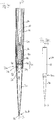
- a pipetting channel is generally designated 10.
- the pipetting channel 10 extends along a Pipettierkanalachse P, which preferably passes through the pipetting channel centrally.
- the pipetting channel 10 may have, for example radially with respect to the Pipettierkanalachse P outermost, a movable in the axial direction stripper sleeve 12, which starting from the in Fig. 1a shown retracted position in the direction of the arrow U can be driven to move.
- the pipetting channel 10 may further include, for example, radially in relation to the stripper sleeve 12 further inwardly, a cylinder 14, in which a piston 16 for changing a volume and thus a pressure of a working fluid in Fig. 1a axially movably received below the piston 16 in the axial direction.
- the piston 16 can be connected in a manner known per se with an axially movable piston rod 18, for instance with an intermediate arrangement of a connecting element 20.
- the pipetting channel 10 can have a coupling formation 22, which can be connected to the cylinder 14, for example via a connecting member 24.
- the connecting member 24 can be plugged onto a connecting end 14a of the cylinder 14 and, if appropriate, additionally adhesively bonded thereto.
- a connecting longitudinal end 22a of the coupling formation 22 can be screwed or clipped onto the connecting member 24.
- the connecting longitudinal end 22a can be glued, welded or otherwise connected inseparably to the connecting member.
- the joints of the coupling formation 22 with the connecting member 24 and the connecting member 24 with the cylinder 14 are located radially inside the stripping sleeve 12 and are surrounded by this and shielded from external influences.
- the coupling formation 22 has a pressure communication opening 26, through which a working fluid pressure prevailing immediately below the piston surface 16a can be transferred into a metering space 28 of a pipetting tip 30 which can be coupled to the coupling formation 22.
- the pipette tip 30 is only an exemplary embodiment of a general working device. Instead of the pipetting tip 30, another laboratory device, such as a wire tool, such as a "MTP plate" can be coupled to the coupling formation 22.
- the pressure-transmitting opening 26 is formed in an end portion 38 which is attributable to the free longitudinal end 22b of the coupling formation.
- the pipetting tip 30 has, in a manner known per se, a coupling longitudinal end 30a and a metering longitudinal end 30b.
- the coupling longitudinal end 30a is formed with a coupling portion 31 for coupling to the free longitudinal end 22b of the coupling formation 22, while the Dosierlnature 30b in a conventional manner, a pipetting 32 has (see Fig. 3a ), through which a liquid by means of a Pressure change of the working fluid in the metering chamber 28 of the pipetting tip 30 into aspiratable and can be dispensed out of this.
- the coupling longitudinal end 30a of the pipetting tip 30 is formed in a manner known per se, to be plugged radially outside the coupling formation 22 surrounding this in Aufsteckraum A.
- the free longitudinal end 22b of the coupling formation 22 can be inserted into a coupling recess 34 formed in the coupling longitudinal end 30a of the pipetting tip 30 and latched there.
- a retaining recess 36 running around a pipette tip axis S can be provided as a latching recess in the coupling recess 34.
- the pipetting channel axis P and the pipette tip axis S are usually collinear.
- the pipetting tip 30 for the process of coupling to the coupling formation 22 should already be aligned, as far as possible, with the pipetting tip axis S which is coollinear with the pipetting channel axis P.
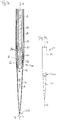
- the coupling formation 22 may have a channel portion 40 which is attributable to the coupling longitudinal end 22a of the coupling formation.
- a spring arrangement 42 may be arranged, which cooperates with a plurality of substantially non-deformable, but against the elastic spring force of the spring assembly 22 radially displaceable part coupling projections 44.
- the entirety of the partial coupling projections 44 forms a coupling projection in the sense of this application.
- the spring assembly 42 advantageously comprises a plurality of leaf spring assemblies 46, which may advantageously be arranged to save space parallel to Pipettierkanalachse P running. This means their largest dimension as a longitudinal dimension parallel to Pipettierkanalachse P runs.
- a gap 48 is preferably provided between two circumferentially immediately adjacent leaf spring assemblies 46 such that the leaf spring assemblies 46 are spaced circumferentially.
- the leaf spring assemblies 46 are formed integrally with the channel portion 40 at their longitudinal ends remote from the pressure communication port 26. Likewise advantageously, the leaf spring assemblies 46 may be formed integrally with the end portion 38 at its longitudinal end closer to the pressure communication port 26.
- the plurality of Operakopplungsvorsprüngen 44 are integrally formed with the leaf spring assemblies 46, preferably a 1: 1 assignment is such that each leaf spring assembly 46 exactly one Detailkopplungsvorsprung 44 is formed and each Generalkopplungsvorsprung 44 with exactly one leaf spring assembly 46 cooperates and against the radial force of the same radial to Pipettierkanalachse P is displaced.
- the pipetting channel 10 can have a sealing ring 50, which advantageously completely surrounds the pipetting channel axis, and surrounds the coupling formation 22 radially outwardly such that a contact surface pointing radially outwards, with the pipetting tip 30 coupled to the coupling formation 22, contacts a corresponding counter-bearing surface 52 in the FIG Coupling recess 34 can pass to seal the coupling region between the coupling formation 22 and pipette tip 30 to the outside environment and to avoid a loss of working fluid pressure by a leak there.
- a sealing ring 50 which advantageously completely surrounds the pipetting channel axis, and surrounds the coupling formation 22 radially outwardly such that a contact surface pointing radially outwards, with the pipetting tip 30 coupled to the coupling formation 22, contacts a corresponding counter-bearing surface 52 in the FIG Coupling recess 34 can pass to seal the coupling region between the coupling formation 22 and pipette tip 30 to the outside environment and to avoid a loss of working fluid pressure
- the sealing ring 50 is located axially further from the pressure communication port 26 than the partial coupling projections 44, so that the latter are unaffected in their coupling action by the sealing engagement of the sealing ring 50 with the pipetting tip 30.
- the sealing ring 50 may be made of a material which, with the same initial shape and the same mechanical load, deforms more than the material of the coupling formation and / or the material of the pipette tip 30. Thus, the sealing ring 50 may possibly form gaps between the pipetting tip and the coupling formation 22 due to deformation fill and close.
- the coupling formation 22 is, as shown in the present example, preferably integrally formed as an injection molded part, wherein at the connecting longitudinal end, if desired, a thread can be provided which can already be produced during injection molding, which, however, the demolding of the coupling formation from the injection mold difficult, or which subsequently can be cut into the component.
- a coupling process of the pipette tip 30 is shown to the coupling formation 22.
- An inner wall of the coupling recess 34, in particular the axially opposite the retaining recess 36 located seal counter-bearing surface 52 presses to the in the Fig. 2a and 2b shown, the partial coupling projections 44 against the spring force of the leaf spring assemblies 46 radially inward to the Pipettierkanalachse, so that the pipetting tip 30 can be plugged with its coupling-side longitudinal end 30a in Aufsteckutter A on the coupling formation 22.
- the pipetting tip 30 is shown completely on the coupling formation 22 and thus coupled to the pipetting channel 10 state.
- the partial coupling projections 44 driven by the elastic force of the leaf spring arrangements 46, are engaged in the retaining recess 36 and thus produce a positive coupling between the pipetting tip 30 and the coupling formation 22.
- the positive coupling which is preferably a catchable catch, be reinforced by a frictional engagement between the materials and components involved.
- Both the positioning abutment surface 54 on the coupling formation 22 and the positioning counter abutment surface 56 on the pipette tip 30 are formed in the example illustrated by radial shoulders, in the case of the coupling formation 22 by a radial shoulder between the end portion 38 and the spring arrangement 42.
- a circumferential surface of the end section 38 pointing in the radial direction is preferably in engaging engagement with a corresponding one in the radial direction facing counter-bearing surface 60 of the pipette tip 30 to align the pipetting tip 30 also in the radial direction with respect to the Pipettierkanalachse P.
- the form-fitting engagement of the partial coupling projections 44 in the retaining recess 36 is preferably designed such that a resulting biasing force acts on the pipetting tip 30, which biases them in the mounting direction A.
- this can be achieved, for example, in that the partial coupling projections 44 abut only on a surface section of the concave retaining recess 36, which is closer to the sealing contact surface 52 and points toward the pipetting longitudinal end 30b.
- the sealing abutment surface 52 on the radially outwardly facing surface of the sealing ring 50 advantageously extends beyond the axial longitudinal end of the gaps 48 provided between the circumferentially adjacent leaf spring assemblies 46.
- Fig. 4a It is shown how, by movement of the pipetting piston 16 toward the pressure-transmitting opening 26, the desired locking positioning of the partial coupling projections 44 can be checked or even produced with the pipetting tip 30 coupled to the coupling formation 22.
- the piston 16 is lowered so far to the Durckvarsö réelle 26 that its piston surface 16a closer to the Druckvalsö réelle 26 is located as the Operakopplungsvorsprünge 44.
- the Railkopplungsvorsprünge 44 are preferably in a direction Pipettierkanalachse P. orthogonal arrangement plane.
- these and / or the leaf spring assemblies 46 may have radially inwardly extending projections 62 which are dimensioned in the radial direction such that the clear width between opposing projections 62 with correct positioning of the Teikopplungsvorsprünge 44 and the cooperating with them leaf spring assemblies 46 of the outer dimension of the piston 16 corresponds.
- the stripper sleeve 12 is moved in the direction of the arrow U relative to the coupling formation 22.
- the stripper sleeve 12 has a contact surface 64 pointing in the axial direction toward the coupling formation 22, with which the latter comes into abutting engagement with a counter-bearing surface 66 of the pipette tip 30 pointing in the axial direction to the stripper sleeve 12 during stripping.
- the contact surface 64 of the Abstreifhülse 12 with respect to the Pipettierkanalachse P or with respect to the direction of movement U is not orthogonal, but provided with a predetermined inclination with respect to Pipettierkanalachse P orthogonal plane, while the counter-contact surface 66 of the pipette 30 in the on Coupling training 22 coupled state is advantageously located in a direction PipollierkanallNicolsachse P and thus collinear pipette tip axis S orthogonal plane.
- any working device can be coupled to the coupling formation 22 presented here or released from it, as long as the coupling portion 31 of the trained for coupling with the coupling training 22 working with the present necessary for coupling with the coupling training 22 technical Features is equipped.
Landscapes
- Engineering & Computer Science (AREA)
- General Engineering & Computer Science (AREA)
- Health & Medical Sciences (AREA)
- Clinical Laboratory Science (AREA)
- Chemical & Material Sciences (AREA)
- Chemical Kinetics & Catalysis (AREA)
- Mechanical Engineering (AREA)
- Devices For Use In Laboratory Experiments (AREA)
- Sampling And Sample Adjustment (AREA)
- Automatic Analysis And Handling Materials Therefor (AREA)
- Quick-Acting Or Multi-Walled Pipe Joints (AREA)
Claims (17)
- Arrangement d'accouplement (22) d'un canal de pipettage (10) d'un dispositif de pipettage pour accoupler un dispositif de travail (30) comme par exemple une pointe de pipette (30) ou un appareil de laboratoire, outil de laboratoire etc., l'arrangement d'accouplement (22) entourant une section de canal de pipettage qui s'étend le long d'un axe de canal de pipettage (P) définissant un sens axial, l'arrangement d'accouplement (22) comprenant en outre une ouverture de transmission de pression (26) à son extrémité longitudinale libre (22b) dans laquelle la section de canal de pipettage aboutit, et comprenant à sa surface enveloppante entourant l'axe de canal de pipettage (P) et s'étendant principalement dans le sens axial et dans les sens circonférentiel autour de l'axe de canal de pipettage (P) radialement extérieure par rapport à l'axe de canal de pipettage (P) une projection d'accouplement (44) flexible dans le sens radial,
caractérisé en ce que la projection d'accouplement (44) est prévu essentiellement non-déformable mais radialement déplaçable à un arrangement de ressort (42) élastique dans le sens radial. - Arrangement d'accouplement selon la revendication 1,
caractérisé en ce que la projection d'accouplement (44) sans charge peut être déplacée radialement contre la force élastique de l'arrangement de ressort (42) par une force radiale dirigée radialement vers l'intérieur envers l'axe de canal de pipettage (P). - Arrangement d'accouplement selon les revendication 1 ou 2,
caractérisé en ce que la projection d'accouplement (44) entoure entièrement l'axe de canal de pipettage (P). - Arrangement d'accouplement selon une des revendications précédentes,
caractérisé en ce que l'arrangement de ressort (42) comprend au moins un arrangement de ressort en feuille (46) qui s'étend d'une extrémité axiale plus loin de l'ouverture de transmission de pression vers une extrémité axiale plus proche de l'ouverture de transmission de pression. - Arrangement d'accouplement selon la revendication 4,
caractérisé en ce que ledit au moins un arrangement de ressort en feuille (46) est à son extrémité axiale plus proche de l'ouverture de transmission de pression fermement lié à une section terminale (38) de l'arrangement d'accouplement (22) comprenant l'ouverture de transmission de pression (26) et en ce que l'arrangement de ressort en feuille (46) est à son extrémité axiale plus loin de l'ouverture de transmission de pression fermement lié à une section du côté canal (40) de l'arrangement d'accouplement (22). - Arrangement d'accouplement selon une des revendications précédentes,
caractérisé en ce que la projection d'accouplement (44) est divisée en une pluralité de projections d'accouplement partielles (44) dont chacune est prévue à un arrangement de ressort (42) élastique dans le sens radial, en particulier à un arrangement de ressort en feuille (46). - Arrangement d'accouplement selon la revendication 6,
caractérisé en ce que qu'il comprend une pluralité d'arrangements de ressort en feuille (46), de préférence parallèles, dont chacun comprend une projection d'accouplement partielle (44). - Arrangement d'accouplement selon la revendication 7,
caractérisé en ce que deux arrangements de ressort en feuille (46) directement adjacents dans le sens circonférentiel comprennent entre eux une fente circonférentielle (48) et sont donc espacés dans le sens circonférentiel. - Arrangement d'accouplement selon une des revendications 7 ou 8,
caractérisé en ce qu'au moins une projection d'accouplement partielle (44) de préférence une pluralité de projections d'accouplement partielles (44), de manière encore plus préférée toutes les projections d'accouplement partielles (44) sont adaptées en une seule pièce avec l'arrangement de ressort en feuille (46) qui les porte respectivement. - Arrangement d'accouplement selon une des revendications précédentes, en particulier en prenant en considération la revendication 5,
caractérisé en ce qu'à une section d'extrémité (38) de l'arrangement d'accouplement (22) comprenant l'ouverture de transmission de pression (26) un arrangement de sécurisation de position (54, 58) et prévu pour sécuriser le positionnement d'une pointe de pipette (30) accouplée à l'arrangement d'accouplement (22) relatif à l'arrangement d'accouplement (22). - Arrangement d'accouplement selon la revendication 10,
caractérisé en ce que ledit arrangement de sécurisation de position (54, 58) comprend un palier radial (à 54) ou/et une section cylindrique (58) s'étendant le long de l'axe de canal de pipetage ou/et une surface conique. - Arrangement d'accouplement selon une des revendications précédentes,
caractérisé en ce qu'il comprend une bague d'étanchéité (50) entourant l'arrangement d'accouplement (22) qui est adaptée pour rendre étanche au gaz contre l'environnement extérieur un volume de pipetage (28) à l'intérieur de la pointe de pipette (30) à une section d'accouplement (30a) de la pointe de pipette (30) dans un état d'accouplement avec la pointe de pipette (30) accouplée à l'arrangement d'accouplement (22). - Arrangement d'accouplement selon la revendication 12,
caractérisé en ce que ladite bague d'étanchéité (50) est adaptée se rajeunissant vers l'ouverture de transmission de pression (26) au moins dans une section axiale. - Arrangement d'accouplement selon la revendication 12 ou 13,
caractérisé en ce que ladite bague d'étanchéité (50) est arrangée plus loin de l'extrémité longitudinale libre (22b) de l'arrangement d'accouplement (22) que la projection d'accouplement (44). - Arrangement d'accouplement selon une des revendications précédentes,
caractérisé en ce que l'arrangement de ressort (42), la projection d'accouplement (44), une section d'extrémité (38) de l'arrangement d'accouplement comprenant l'ouverture de transmission de pression (26), et une section du côté canal (40) de l'arrangement d'accouplement située axialement plus loin de l'extrémité longitudinale libre (22b) de l'arrangement d'accouplement (22) que l'arrangement de ressort (42) sont formés en une seule pièce. - Dispositif de pipetage avec un arrangement d'accouplement (22) selon une des revendications précédentes et avec un canal de pipetage (10) dont la section de canal de pipetage de l'arrangement d'accouplement (22) forme une section,
caractérisé en ce que le dispositif de pipetage comprend un piston de pipetage (16) qui au moins à son extrémité longitudinale plus proche de l'ouverture de transmission de pression (à 16a) est dimensionné de sorte et est reçu au dispositif de pipetage dans le canal de pipetage de manière mobile de sorte qu'il peut être inséré axialement dans la section de canal de pipetage de l'arrangement d'accouplement (22) et peut être sorti de cette dernière de sorte que son extrémité plus proche de l'ouverture de transmission de pression (à 16a) est plus proche de l'ouverture de transmission de pression (26) que la projection d'accouplement (44). - Dispositif de pipetage avec un arrangement d'accouplement (22) selon une des revendications précédentes et avec un canal de pipetage (10) dont la section de canal de pipetage de l'arrangement d'accouplement (22) forme une section, selon la revendication 16, le dispositif de pipetage comprenant un dispositif de raclage (12) axialement mobile qui est adapté pour entrer pendant un mouvement axiale de raclage avec une surface d'appui (64) en engagement d'appui avec une contre-surface d'appui (66) d'un dispositif de travail (30) accouplé à l'arrangement d'accouplement (22), par exemple d'une pointe de pipette (30) ou d'un appareil de laboratoire, outil de laboratoire etc. pour racler, en continuant le mouvement de raclage après la réalisation de l'engagement en appui, la pointe de pipette (30) de l'arrangement d'accouplement (22) et pour la découpler de cette manière du dispositif de pipetage,
caractérisé en ce que la surface d'appui (64) du dispositif de raclage (12) est inclinée ou courbée par rapport au sens de mouvement axial (U) du mouvement de raclage.
Applications Claiming Priority (2)
| Application Number | Priority Date | Filing Date | Title |
|---|---|---|---|
| DE102012213089.6A DE102012213089A1 (de) | 2012-07-25 | 2012-07-25 | Kopplungsausbildung eines Pipettierkanals einer Pipettiervorrichtung zur Ankopplung einer Pipettierspitze daran |
| PCT/EP2013/065485 WO2014016282A1 (fr) | 2012-07-25 | 2013-07-23 | Système de raccordement d'un embout de pipetage à un conduit de pipetage d'un dispositif de pipetage |
Publications (2)
| Publication Number | Publication Date |
|---|---|
| EP2877283A1 EP2877283A1 (fr) | 2015-06-03 |
| EP2877283B1 true EP2877283B1 (fr) | 2018-09-19 |
Family
ID=48874287
Family Applications (1)
| Application Number | Title | Priority Date | Filing Date |
|---|---|---|---|
| EP13740273.1A Active EP2877283B1 (fr) | 2012-07-25 | 2013-07-23 | Système de raccordement d'un embout de pipetage à un conduit de pipetage d'un dispositif de pipetage |
Country Status (7)
| Country | Link |
|---|---|
| US (1) | US9803789B2 (fr) |
| EP (1) | EP2877283B1 (fr) |
| JP (1) | JP6271542B2 (fr) |
| CN (1) | CN104507578B (fr) |
| DE (1) | DE102012213089A1 (fr) |
| ES (1) | ES2696078T3 (fr) |
| WO (1) | WO2014016282A1 (fr) |
Families Citing this family (13)
| Publication number | Priority date | Publication date | Assignee | Title |
|---|---|---|---|---|
| DE102014108688A1 (de) * | 2014-06-20 | 2015-12-24 | Hamilton Bonaduz Ag | Pipettiervorrichtung mit modularem Pipettierkopf |
| EP3219826A4 (fr) | 2014-11-12 | 2017-11-22 | JFE Steel Corporation | Procédé permettant la fabrication de tôle d'acier galvanisée |
| EP3112026B1 (fr) * | 2015-06-30 | 2018-03-14 | Sartorius Biohit Liquid Handling Oy | Pipette avec un mécanisme de retrait de pointe, procédé pour retirer une pointe et procédé de pipettage |
| DE102015213005A1 (de) * | 2015-07-10 | 2017-01-12 | Hamilton Bonaduz Ag | Pipettiervorrichtung mit ausstülpbarer Kopplungsformation zur Ankopplung einer Pipettierspitze sowie hierfür ausgebildete Pipettierspitze |
| US10300480B2 (en) | 2015-10-13 | 2019-05-28 | Roche Molecular Systems, Inc. | Pipetting device for an apparatus for processing a sample or reagent, apparatus for processing a sample or reagent and method for pipetting a sample or reagent |
| EP3578260B1 (fr) | 2016-06-15 | 2021-10-13 | Hamilton Company | Pointe de pipette |
| US10898892B2 (en) | 2016-06-15 | 2021-01-26 | Hamilton Company | Pipetting device, pipette tip coupler, and pipette tip: devices and methods |
| US11065614B2 (en) | 2016-06-15 | 2021-07-20 | Hamilton Company | Pipetting device, pipette tip coupler, and pipette tip: devices and methods |
| US11235318B2 (en) | 2016-06-15 | 2022-02-01 | Hamilton Company | Pipetting device, pipette tip coupler, and pipette tip: devices and methods |
| DE102018215559A1 (de) * | 2018-09-12 | 2020-03-12 | Hamilton Bonaduz Ag | Pipettierkolben-Dichtungsanordnung mit justierbarer Anpresskraft eines Dichtflächenabschnitts |
| USD901035S1 (en) | 2019-07-18 | 2020-11-03 | CLAS Automation | Pipette with a flared end |
| JP7377985B2 (ja) | 2020-07-31 | 2023-11-10 | ハミルトン カンパニー | ピペッティングデバイス、ピペットチップカップラー、およびピペットチップ:デバイスおよび方法 |
| CN117244602B (zh) * | 2023-09-28 | 2024-05-24 | 康容生物科技(太仓)有限公司 | 一种一体成型外置活塞移液器吸头 |
Family Cites Families (30)
| Publication number | Priority date | Publication date | Assignee | Title |
|---|---|---|---|---|
| BE625021A (fr) * | 1961-12-02 | |||
| US3639890A (en) * | 1970-06-09 | 1972-02-01 | Bendix Corp | Locking connector assembly |
| US3908925A (en) * | 1974-04-30 | 1975-09-30 | Ibm | Tape cassette opener |
| US3912009A (en) * | 1974-06-12 | 1975-10-14 | Jr Philip E Davis | Latch-in adapter |
| DE2554749C3 (de) * | 1975-12-05 | 1978-05-24 | Ernst Leitz Wetzlar Gmbh, 6330 Wetzlar | Mikroskopobjektivfassung |
| US4616514A (en) * | 1983-06-06 | 1986-10-14 | Rainin Instrument Co., Inc. | Replaceable tip assembly for pipette |
| JPH01132237U (fr) | 1988-02-29 | 1989-09-07 | ||
| US4860838A (en) * | 1988-12-12 | 1989-08-29 | Drill Systems International Ltd. | Latching bit sub |
| US5251938A (en) * | 1991-08-30 | 1993-10-12 | Pro-Mark, Inc. | Adapter pipe fitting for sprinkler or drip-type irrigation systems |
| US5395139A (en) * | 1993-06-29 | 1995-03-07 | Pro-Mark, Inc. | Swivel type adapter pipe fitting for sprinkler or drip-type irrigation systems |
| DE4341229C2 (de) | 1993-12-03 | 1995-09-07 | Eppendorf Geraetebau Netheler | Pipettensystem |
| US5803512A (en) * | 1996-03-22 | 1998-09-08 | Hollnagel; Harold E. | Tube quick connect to female socket |
| US5718463A (en) * | 1995-09-13 | 1998-02-17 | Hollnagel; Harold E. | Tube quick connect to female socket |
| DE19917375C2 (de) * | 1999-04-16 | 2001-09-27 | Hamilton Bonaduz Ag Bonaduz | Pipettiereinheit |
| DE19917549C1 (de) * | 1999-04-19 | 2000-11-02 | Dunkel Otto Gmbh | Steckverbinder |
| US6655491B1 (en) * | 2000-06-09 | 2003-12-02 | Trw Inc. | Power steering apparatus |
| DE10159280B4 (de) * | 2001-12-04 | 2004-12-16 | Kautex Textron Gmbh & Co Kg | Steckverbindung |
| US6733046B1 (en) * | 2002-10-24 | 2004-05-11 | Pollvergnuegen | Hose swivel connection apparatus |
| JP2005062149A (ja) * | 2003-07-30 | 2005-03-10 | Yaskawa Electric Corp | 分注装置 |
| US7641859B2 (en) | 2004-02-11 | 2010-01-05 | Matrix Technologies Corporation | Pipette tip mounting and ejection assembly and associated pipette tip |
| JP2005224906A (ja) * | 2004-02-13 | 2005-08-25 | Tsubakimoto Chain Co | マイクロチューブ用ピッキング工具。 |
| US7249788B2 (en) * | 2004-02-19 | 2007-07-31 | Dana Canada Corporation | Connector assembly for male and female members |
| US7320259B2 (en) * | 2004-03-06 | 2008-01-22 | Medax International, Inc. | Pipette tip for easy separation |
| US7249789B2 (en) * | 2004-10-14 | 2007-07-31 | Johnson Screens, Inc. | Water well casing |
| US7240927B2 (en) * | 2005-06-06 | 2007-07-10 | King Chang | Connection assembly used for connection between a fuel nozzle and a filling hose |
| DE502005002597D1 (de) * | 2005-11-24 | 2008-03-06 | Efs Eberle Feinwerktechnische | Chirurgische Kupplungsvorrichtung |
| EP1862219B1 (fr) * | 2006-05-29 | 2018-02-07 | Qiagen GmbH | Appareil pour retenir un embout à pipette et pipette utilisant ledit embout |
| US8557197B2 (en) | 2008-11-05 | 2013-10-15 | Hamilton Bonaduz Ag | Radial sliding seal component for metering devices and metering device having such a radial sliding seal component |
| DE102010001229A1 (de) * | 2010-01-26 | 2011-07-28 | Hamilton Bonaduz Ag | Verfahren und Vorrichtung zur Bestimmung eines flüssigkeitsspezifischen oder vom Benetzungszustand einer Pipettierspitze abhängigen Parameters durch Schwingungsanregung |
| FI123648B (fi) * | 2010-11-15 | 2013-08-30 | Thermo Fisher Scientific Oy | Monikanavapipetti |
-
2012
- 2012-07-25 DE DE102012213089.6A patent/DE102012213089A1/de not_active Withdrawn
-
2013
- 2013-07-23 ES ES13740273T patent/ES2696078T3/es active Active
- 2013-07-23 JP JP2015523524A patent/JP6271542B2/ja active Active
- 2013-07-23 WO PCT/EP2013/065485 patent/WO2014016282A1/fr active Application Filing
- 2013-07-23 CN CN201380039377.1A patent/CN104507578B/zh active Active
- 2013-07-23 US US14/417,336 patent/US9803789B2/en active Active
- 2013-07-23 EP EP13740273.1A patent/EP2877283B1/fr active Active
Non-Patent Citations (1)
| Title |
|---|
| None * |
Also Published As
| Publication number | Publication date |
|---|---|
| JP2015530230A (ja) | 2015-10-15 |
| EP2877283A1 (fr) | 2015-06-03 |
| CN104507578A (zh) | 2015-04-08 |
| ES2696078T3 (es) | 2019-01-14 |
| WO2014016282A1 (fr) | 2014-01-30 |
| DE102012213089A1 (de) | 2014-01-30 |
| CN104507578B (zh) | 2017-03-08 |
| JP6271542B2 (ja) | 2018-01-31 |
| US9803789B2 (en) | 2017-10-31 |
| US20150276107A1 (en) | 2015-10-01 |
Similar Documents
| Publication | Publication Date | Title |
|---|---|---|
| EP2877283B1 (fr) | Système de raccordement d'un embout de pipetage à un conduit de pipetage d'un dispositif de pipetage | |
| EP1049501B1 (fr) | Appareil d'injection | |
| EP1958660B1 (fr) | Raccord Luer Lock à baïonnette pour une pompe à insuline | |
| DE212009000058U1 (de) | Sicherheitsspritze | |
| DE102015000990B4 (de) | Anschlussvorrichtung für eine Fluidleitung | |
| WO2007025704A1 (fr) | Barre de prehension pour seringue assurant une meilleure protection contre la rupture | |
| EP3319730B1 (fr) | Dispositif de pipetage muni d'une structure de raccordement retournée vers l'extérieur servant au raccordement d'une pointe de pipette, ainsi que pointe de pipette conçue à cette fin | |
| DE3027827A1 (de) | Steckverbinder fuer lichtwellenleiter | |
| EP3127601B1 (fr) | Dispositif de melange, en particulier pour ciment osseux | |
| EP0885599B1 (fr) | Applicateur | |
| WO2005059426A1 (fr) | Raccord de conduite emboitable et blocable | |
| WO2002026296A1 (fr) | Seringue composee d'un cylindre recevant un milieu liquide et d'un capuchon de fermeture | |
| EP2898913B1 (fr) | Seringue | |
| EP2160216B8 (fr) | Seringue à usage unique comprenant une protection contre la réutilisation | |
| WO2008086763A1 (fr) | Cylindre récepteur | |
| DE102008004027A1 (de) | Nehmerzylinder | |
| DE102005003516B3 (de) | Blutentnahmereservoir | |
| DE10162658B4 (de) | Anschlussstück für Fluidleitungen und damit ausgestattetes fluidtechnisches Gerät | |
| WO2012119578A1 (fr) | Pistolet à peinture comprenant une zone de guidage de peinture et une aiguille | |
| EP2873430B1 (fr) | Manette pour une seringue | |
| DE19756598B4 (de) | Vorrichtung zum Verbinden von Schnüren | |
| EP3926226A1 (fr) | Élément d'accouplement pour un accouplement hydraulique | |
| EP2982893B1 (fr) | Dispositif de serrage de tuyau | |
| EP2796206B1 (fr) | Tête de distribution associée à un récipient et procédé de fixation d'une tête de distribution sur un récipient | |
| DE102005042641B3 (de) | Sicherheitsspritze |
Legal Events
| Date | Code | Title | Description |
|---|---|---|---|
| PUAI | Public reference made under article 153(3) epc to a published international application that has entered the european phase |
Free format text: ORIGINAL CODE: 0009012 |
|
| 17P | Request for examination filed |
Effective date: 20141208 |
|
| AK | Designated contracting states |
Kind code of ref document: A1 Designated state(s): AL AT BE BG CH CY CZ DE DK EE ES FI FR GB GR HR HU IE IS IT LI LT LU LV MC MK MT NL NO PL PT RO RS SE SI SK SM TR |
|
| AX | Request for extension of the european patent |
Extension state: BA ME |
|
| DAX | Request for extension of the european patent (deleted) | ||
| REG | Reference to a national code |
Ref country code: DE Ref legal event code: R079 Ref document number: 502013011126 Country of ref document: DE Free format text: PREVIOUS MAIN CLASS: B01L0003020000 Ipc: F16L0021035000 |
|
| GRAP | Despatch of communication of intention to grant a patent |
Free format text: ORIGINAL CODE: EPIDOSNIGR1 |
|
| STAA | Information on the status of an ep patent application or granted ep patent |
Free format text: STATUS: GRANT OF PATENT IS INTENDED |
|
| RIC1 | Information provided on ipc code assigned before grant |
Ipc: F16L 21/035 20060101AFI20180320BHEP Ipc: F16L 37/086 20060101ALI20180320BHEP Ipc: B01L 3/02 20060101ALI20180320BHEP Ipc: F16L 21/08 20060101ALI20180320BHEP |
|
| INTG | Intention to grant announced |
Effective date: 20180411 |
|
| GRAS | Grant fee paid |
Free format text: ORIGINAL CODE: EPIDOSNIGR3 |
|
| GRAA | (expected) grant |
Free format text: ORIGINAL CODE: 0009210 |
|
| STAA | Information on the status of an ep patent application or granted ep patent |
Free format text: STATUS: THE PATENT HAS BEEN GRANTED |
|
| AK | Designated contracting states |
Kind code of ref document: B1 Designated state(s): AL AT BE BG CH CY CZ DE DK EE ES FI FR GB GR HR HU IE IS IT LI LT LU LV MC MK MT NL NO PL PT RO RS SE SI SK SM TR |
|
| RAP1 | Party data changed (applicant data changed or rights of an application transferred) |
Owner name: HAMILTON BONADUZ AG |
|
| REG | Reference to a national code |
Ref country code: GB Ref legal event code: FG4D Free format text: NOT ENGLISH |
|
| REG | Reference to a national code |
Ref country code: CH Ref legal event code: EP |
|
| REG | Reference to a national code |
Ref country code: AT Ref legal event code: REF Ref document number: 1043634 Country of ref document: AT Kind code of ref document: T Effective date: 20181015 |
|
| REG | Reference to a national code |
Ref country code: IE Ref legal event code: FG4D Free format text: LANGUAGE OF EP DOCUMENT: GERMAN |
|
| REG | Reference to a national code |
Ref country code: DE Ref legal event code: R096 Ref document number: 502013011126 Country of ref document: DE |
|
| REG | Reference to a national code |
Ref country code: CH Ref legal event code: NV Representative=s name: E. BLUM AND CO. AG PATENT- UND MARKENANWAELTE , CH |
|
| REG | Reference to a national code |
Ref country code: SE Ref legal event code: TRGR |
|
| REG | Reference to a national code |
Ref country code: NL Ref legal event code: FP |
|
| REG | Reference to a national code |
Ref country code: ES Ref legal event code: FG2A Ref document number: 2696078 Country of ref document: ES Kind code of ref document: T3 Effective date: 20190114 |
|
| PG25 | Lapsed in a contracting state [announced via postgrant information from national office to epo] |
Ref country code: RS Free format text: LAPSE BECAUSE OF FAILURE TO SUBMIT A TRANSLATION OF THE DESCRIPTION OR TO PAY THE FEE WITHIN THE PRESCRIBED TIME-LIMIT Effective date: 20180919 Ref country code: BG Free format text: LAPSE BECAUSE OF FAILURE TO SUBMIT A TRANSLATION OF THE DESCRIPTION OR TO PAY THE FEE WITHIN THE PRESCRIBED TIME-LIMIT Effective date: 20181219 Ref country code: LT Free format text: LAPSE BECAUSE OF FAILURE TO SUBMIT A TRANSLATION OF THE DESCRIPTION OR TO PAY THE FEE WITHIN THE PRESCRIBED TIME-LIMIT Effective date: 20180919 Ref country code: GR Free format text: LAPSE BECAUSE OF FAILURE TO SUBMIT A TRANSLATION OF THE DESCRIPTION OR TO PAY THE FEE WITHIN THE PRESCRIBED TIME-LIMIT Effective date: 20181220 |
|
| REG | Reference to a national code |
Ref country code: NO Ref legal event code: T2 Effective date: 20180919 |
|
| REG | Reference to a national code |
Ref country code: LT Ref legal event code: MG4D |
|
| PG25 | Lapsed in a contracting state [announced via postgrant information from national office to epo] |
Ref country code: HR Free format text: LAPSE BECAUSE OF FAILURE TO SUBMIT A TRANSLATION OF THE DESCRIPTION OR TO PAY THE FEE WITHIN THE PRESCRIBED TIME-LIMIT Effective date: 20180919 Ref country code: LV Free format text: LAPSE BECAUSE OF FAILURE TO SUBMIT A TRANSLATION OF THE DESCRIPTION OR TO PAY THE FEE WITHIN THE PRESCRIBED TIME-LIMIT Effective date: 20180919 Ref country code: AL Free format text: LAPSE BECAUSE OF FAILURE TO SUBMIT A TRANSLATION OF THE DESCRIPTION OR TO PAY THE FEE WITHIN THE PRESCRIBED TIME-LIMIT Effective date: 20180919 |
|
| PG25 | Lapsed in a contracting state [announced via postgrant information from national office to epo] |
Ref country code: IS Free format text: LAPSE BECAUSE OF FAILURE TO SUBMIT A TRANSLATION OF THE DESCRIPTION OR TO PAY THE FEE WITHIN THE PRESCRIBED TIME-LIMIT Effective date: 20190119 Ref country code: EE Free format text: LAPSE BECAUSE OF FAILURE TO SUBMIT A TRANSLATION OF THE DESCRIPTION OR TO PAY THE FEE WITHIN THE PRESCRIBED TIME-LIMIT Effective date: 20180919 Ref country code: CZ Free format text: LAPSE BECAUSE OF FAILURE TO SUBMIT A TRANSLATION OF THE DESCRIPTION OR TO PAY THE FEE WITHIN THE PRESCRIBED TIME-LIMIT Effective date: 20180919 Ref country code: RO Free format text: LAPSE BECAUSE OF FAILURE TO SUBMIT A TRANSLATION OF THE DESCRIPTION OR TO PAY THE FEE WITHIN THE PRESCRIBED TIME-LIMIT Effective date: 20180919 Ref country code: PL Free format text: LAPSE BECAUSE OF FAILURE TO SUBMIT A TRANSLATION OF THE DESCRIPTION OR TO PAY THE FEE WITHIN THE PRESCRIBED TIME-LIMIT Effective date: 20180919 |
|
| PG25 | Lapsed in a contracting state [announced via postgrant information from national office to epo] |
Ref country code: SM Free format text: LAPSE BECAUSE OF FAILURE TO SUBMIT A TRANSLATION OF THE DESCRIPTION OR TO PAY THE FEE WITHIN THE PRESCRIBED TIME-LIMIT Effective date: 20180919 Ref country code: PT Free format text: LAPSE BECAUSE OF FAILURE TO SUBMIT A TRANSLATION OF THE DESCRIPTION OR TO PAY THE FEE WITHIN THE PRESCRIBED TIME-LIMIT Effective date: 20190119 Ref country code: SK Free format text: LAPSE BECAUSE OF FAILURE TO SUBMIT A TRANSLATION OF THE DESCRIPTION OR TO PAY THE FEE WITHIN THE PRESCRIBED TIME-LIMIT Effective date: 20180919 |
|
| REG | Reference to a national code |
Ref country code: DE Ref legal event code: R097 Ref document number: 502013011126 Country of ref document: DE |
|
| PLBE | No opposition filed within time limit |
Free format text: ORIGINAL CODE: 0009261 |
|
| STAA | Information on the status of an ep patent application or granted ep patent |
Free format text: STATUS: NO OPPOSITION FILED WITHIN TIME LIMIT |
|
| PG25 | Lapsed in a contracting state [announced via postgrant information from national office to epo] |
Ref country code: DK Free format text: LAPSE BECAUSE OF FAILURE TO SUBMIT A TRANSLATION OF THE DESCRIPTION OR TO PAY THE FEE WITHIN THE PRESCRIBED TIME-LIMIT Effective date: 20180919 |
|
| 26N | No opposition filed |
Effective date: 20190620 |
|
| PG25 | Lapsed in a contracting state [announced via postgrant information from national office to epo] |
Ref country code: SI Free format text: LAPSE BECAUSE OF FAILURE TO SUBMIT A TRANSLATION OF THE DESCRIPTION OR TO PAY THE FEE WITHIN THE PRESCRIBED TIME-LIMIT Effective date: 20180919 |
|
| PG25 | Lapsed in a contracting state [announced via postgrant information from national office to epo] |
Ref country code: MC Free format text: LAPSE BECAUSE OF FAILURE TO SUBMIT A TRANSLATION OF THE DESCRIPTION OR TO PAY THE FEE WITHIN THE PRESCRIBED TIME-LIMIT Effective date: 20180919 |
|
| PG25 | Lapsed in a contracting state [announced via postgrant information from national office to epo] |
Ref country code: TR Free format text: LAPSE BECAUSE OF FAILURE TO SUBMIT A TRANSLATION OF THE DESCRIPTION OR TO PAY THE FEE WITHIN THE PRESCRIBED TIME-LIMIT Effective date: 20180919 |
|
| REG | Reference to a national code |
Ref country code: BE Ref legal event code: MM Effective date: 20190731 |
|
| PG25 | Lapsed in a contracting state [announced via postgrant information from national office to epo] |
Ref country code: BE Free format text: LAPSE BECAUSE OF NON-PAYMENT OF DUE FEES Effective date: 20190731 Ref country code: LU Free format text: LAPSE BECAUSE OF NON-PAYMENT OF DUE FEES Effective date: 20190723 |
|
| PG25 | Lapsed in a contracting state [announced via postgrant information from national office to epo] |
Ref country code: CY Free format text: LAPSE BECAUSE OF FAILURE TO SUBMIT A TRANSLATION OF THE DESCRIPTION OR TO PAY THE FEE WITHIN THE PRESCRIBED TIME-LIMIT Effective date: 20180919 |
|
| PG25 | Lapsed in a contracting state [announced via postgrant information from national office to epo] |
Ref country code: MT Free format text: LAPSE BECAUSE OF FAILURE TO SUBMIT A TRANSLATION OF THE DESCRIPTION OR TO PAY THE FEE WITHIN THE PRESCRIBED TIME-LIMIT Effective date: 20180919 Ref country code: HU Free format text: LAPSE BECAUSE OF FAILURE TO SUBMIT A TRANSLATION OF THE DESCRIPTION OR TO PAY THE FEE WITHIN THE PRESCRIBED TIME-LIMIT; INVALID AB INITIO Effective date: 20130723 |
|
| PG25 | Lapsed in a contracting state [announced via postgrant information from national office to epo] |
Ref country code: MK Free format text: LAPSE BECAUSE OF FAILURE TO SUBMIT A TRANSLATION OF THE DESCRIPTION OR TO PAY THE FEE WITHIN THE PRESCRIBED TIME-LIMIT Effective date: 20180919 |
|
| PGFP | Annual fee paid to national office [announced via postgrant information from national office to epo] |
Ref country code: SE Payment date: 20220622 Year of fee payment: 10 Ref country code: NO Payment date: 20220623 Year of fee payment: 10 Ref country code: NL Payment date: 20220621 Year of fee payment: 10 Ref country code: IT Payment date: 20220621 Year of fee payment: 10 Ref country code: IE Payment date: 20220623 Year of fee payment: 10 |
|
| PGFP | Annual fee paid to national office [announced via postgrant information from national office to epo] |
Ref country code: FI Payment date: 20220617 Year of fee payment: 10 |
|
| PGFP | Annual fee paid to national office [announced via postgrant information from national office to epo] |
Ref country code: ES Payment date: 20220801 Year of fee payment: 10 Ref country code: AT Payment date: 20220623 Year of fee payment: 10 |
|
| P01 | Opt-out of the competence of the unified patent court (upc) registered |
Effective date: 20230521 |
|
| PGFP | Annual fee paid to national office [announced via postgrant information from national office to epo] |
Ref country code: FR Payment date: 20230621 Year of fee payment: 11 |
|
| PGFP | Annual fee paid to national office [announced via postgrant information from national office to epo] |
Ref country code: GB Payment date: 20230620 Year of fee payment: 11 Ref country code: CH Payment date: 20230801 Year of fee payment: 11 |
|
| PGFP | Annual fee paid to national office [announced via postgrant information from national office to epo] |
Ref country code: DE Payment date: 20230620 Year of fee payment: 11 |
|
| REG | Reference to a national code |
Ref country code: NO Ref legal event code: MMEP |
|
| REG | Reference to a national code |
Ref country code: SE Ref legal event code: EUG |
|
| REG | Reference to a national code |
Ref country code: NL Ref legal event code: MM Effective date: 20230801 |
|
| REG | Reference to a national code |
Ref country code: AT Ref legal event code: MM01 Ref document number: 1043634 Country of ref document: AT Kind code of ref document: T Effective date: 20230723 |
|
| PG25 | Lapsed in a contracting state [announced via postgrant information from national office to epo] |
Ref country code: NL Free format text: LAPSE BECAUSE OF NON-PAYMENT OF DUE FEES Effective date: 20230801 |
|
| PG25 | Lapsed in a contracting state [announced via postgrant information from national office to epo] |
Ref country code: AT Free format text: LAPSE BECAUSE OF NON-PAYMENT OF DUE FEES Effective date: 20230723 |
|
| REG | Reference to a national code |
Ref country code: IE Ref legal event code: MM4A |
|
| PG25 | Lapsed in a contracting state [announced via postgrant information from national office to epo] |
Ref country code: NL Free format text: LAPSE BECAUSE OF NON-PAYMENT OF DUE FEES Effective date: 20230801 Ref country code: FI Free format text: LAPSE BECAUSE OF NON-PAYMENT OF DUE FEES Effective date: 20230723 Ref country code: AT Free format text: LAPSE BECAUSE OF NON-PAYMENT OF DUE FEES Effective date: 20230723 |