EP2875254B1 - Zusammengesetzte schraubenfeder - Google Patents
Zusammengesetzte schraubenfeder Download PDFInfo
- Publication number
- EP2875254B1 EP2875254B1 EP12753316.4A EP12753316A EP2875254B1 EP 2875254 B1 EP2875254 B1 EP 2875254B1 EP 12753316 A EP12753316 A EP 12753316A EP 2875254 B1 EP2875254 B1 EP 2875254B1
- Authority
- EP
- European Patent Office
- Prior art keywords
- fibers
- fiber layers
- core
- fiber
- positive non
- Prior art date
- Legal status (The legal status is an assumption and is not a legal conclusion. Google has not performed a legal analysis and makes no representation as to the accuracy of the status listed.)
- Active
Links
- 239000002131 composite material Substances 0.000 title claims description 41
- 239000000835 fiber Substances 0.000 claims description 176
- 239000002861 polymer material Substances 0.000 claims description 11
- 239000000463 material Substances 0.000 claims description 7
- 238000004519 manufacturing process Methods 0.000 claims description 5
- 239000007787 solid Substances 0.000 claims description 5
- 239000004593 Epoxy Substances 0.000 claims description 3
- 239000000945 filler Substances 0.000 claims description 3
- 238000000034 method Methods 0.000 claims description 3
- 229920000728 polyester Polymers 0.000 claims description 3
- 229920000049 Carbon (fiber) Polymers 0.000 claims description 2
- 229920000914 Metallic fiber Polymers 0.000 claims description 2
- 239000004760 aramid Substances 0.000 claims description 2
- 229920006231 aramid fiber Polymers 0.000 claims description 2
- 239000004917 carbon fiber Substances 0.000 claims description 2
- 239000000919 ceramic Substances 0.000 claims description 2
- 239000003365 glass fiber Substances 0.000 claims description 2
- 239000012781 shape memory material Substances 0.000 claims description 2
- 239000000203 mixture Substances 0.000 description 4
- 239000000725 suspension Substances 0.000 description 3
- 229910000831 Steel Inorganic materials 0.000 description 2
- 230000008901 benefit Effects 0.000 description 2
- 230000015572 biosynthetic process Effects 0.000 description 2
- 238000010438 heat treatment Methods 0.000 description 2
- 229920000642 polymer Polymers 0.000 description 2
- 229920005989 resin Polymers 0.000 description 2
- 239000011347 resin Substances 0.000 description 2
- 239000010959 steel Substances 0.000 description 2
- 238000004804 winding Methods 0.000 description 2
- 239000000446 fuel Substances 0.000 description 1
- 238000012986 modification Methods 0.000 description 1
- 230000004048 modification Effects 0.000 description 1
- 229920000620 organic polymer Polymers 0.000 description 1
- 239000002952 polymeric resin Substances 0.000 description 1
- 230000008569 process Effects 0.000 description 1
- 230000004044 response Effects 0.000 description 1
- 229920003002 synthetic resin Polymers 0.000 description 1
- 239000013585 weight reducing agent Substances 0.000 description 1
Images
Classifications
-
- F—MECHANICAL ENGINEERING; LIGHTING; HEATING; WEAPONS; BLASTING
- F16—ENGINEERING ELEMENTS AND UNITS; GENERAL MEASURES FOR PRODUCING AND MAINTAINING EFFECTIVE FUNCTIONING OF MACHINES OR INSTALLATIONS; THERMAL INSULATION IN GENERAL
- F16F—SPRINGS; SHOCK-ABSORBERS; MEANS FOR DAMPING VIBRATION
- F16F1/00—Springs
- F16F1/36—Springs made of rubber or other material having high internal friction, e.g. thermoplastic elastomers
- F16F1/366—Springs made of rubber or other material having high internal friction, e.g. thermoplastic elastomers made of fibre-reinforced plastics, i.e. characterised by their special construction from such materials
- F16F1/3665—Wound springs
-
- B—PERFORMING OPERATIONS; TRANSPORTING
- B29—WORKING OF PLASTICS; WORKING OF SUBSTANCES IN A PLASTIC STATE IN GENERAL
- B29C—SHAPING OR JOINING OF PLASTICS; SHAPING OF MATERIAL IN A PLASTIC STATE, NOT OTHERWISE PROVIDED FOR; AFTER-TREATMENT OF THE SHAPED PRODUCTS, e.g. REPAIRING
- B29C70/00—Shaping composites, i.e. plastics material comprising reinforcements, fillers or preformed parts, e.g. inserts
- B29C70/04—Shaping composites, i.e. plastics material comprising reinforcements, fillers or preformed parts, e.g. inserts comprising reinforcements only, e.g. self-reinforcing plastics
- B29C70/06—Fibrous reinforcements only
- B29C70/08—Fibrous reinforcements only comprising combinations of different forms of fibrous reinforcements incorporated in matrix material, forming one or more layers, and with or without non-reinforced layers
- B29C70/083—Combinations of continuous fibres or fibrous profiled structures oriented in one direction and reinforcements forming a two dimensional structure, e.g. mats
- B29C70/085—Combinations of continuous fibres or fibrous profiled structures oriented in one direction and reinforcements forming a two dimensional structure, e.g. mats the structure being deformed in a three dimensional configuration
-
- B—PERFORMING OPERATIONS; TRANSPORTING
- B29—WORKING OF PLASTICS; WORKING OF SUBSTANCES IN A PLASTIC STATE IN GENERAL
- B29K—INDEXING SCHEME ASSOCIATED WITH SUBCLASSES B29B, B29C OR B29D, RELATING TO MOULDING MATERIALS OR TO MATERIALS FOR MOULDS, REINFORCEMENTS, FILLERS OR PREFORMED PARTS, e.g. INSERTS
- B29K2277/00—Use of PA, i.e. polyamides, e.g. polyesteramides or derivatives thereof, as reinforcement
-
- B—PERFORMING OPERATIONS; TRANSPORTING
- B29—WORKING OF PLASTICS; WORKING OF SUBSTANCES IN A PLASTIC STATE IN GENERAL
- B29K—INDEXING SCHEME ASSOCIATED WITH SUBCLASSES B29B, B29C OR B29D, RELATING TO MOULDING MATERIALS OR TO MATERIALS FOR MOULDS, REINFORCEMENTS, FILLERS OR PREFORMED PARTS, e.g. INSERTS
- B29K2307/00—Use of elements other than metals as reinforcement
- B29K2307/04—Carbon
-
- B—PERFORMING OPERATIONS; TRANSPORTING
- B29—WORKING OF PLASTICS; WORKING OF SUBSTANCES IN A PLASTIC STATE IN GENERAL
- B29K—INDEXING SCHEME ASSOCIATED WITH SUBCLASSES B29B, B29C OR B29D, RELATING TO MOULDING MATERIALS OR TO MATERIALS FOR MOULDS, REINFORCEMENTS, FILLERS OR PREFORMED PARTS, e.g. INSERTS
- B29K2309/00—Use of inorganic materials not provided for in groups B29K2303/00 - B29K2307/00, as reinforcement
- B29K2309/08—Glass
-
- B—PERFORMING OPERATIONS; TRANSPORTING
- B29—WORKING OF PLASTICS; WORKING OF SUBSTANCES IN A PLASTIC STATE IN GENERAL
- B29L—INDEXING SCHEME ASSOCIATED WITH SUBCLASS B29C, RELATING TO PARTICULAR ARTICLES
- B29L2031/00—Other particular articles
- B29L2031/774—Springs
- B29L2031/7742—Springs helical springs
-
- B—PERFORMING OPERATIONS; TRANSPORTING
- B60—VEHICLES IN GENERAL
- B60G—VEHICLE SUSPENSION ARRANGEMENTS
- B60G11/00—Resilient suspensions characterised by arrangement, location or kind of springs
- B60G11/14—Resilient suspensions characterised by arrangement, location or kind of springs having helical, spiral or coil springs only
Definitions
- This disclosure relates to composite coil springs that may be used in vehicle suspension systems.
- Coil springs are known and used in a variety of different applications, such as vehicle suspension systems.
- a typical coil spring is fabricated of a steel material in order to provide the desired mechanical properties and durability that is required for such applications.
- composite coil springs are desired as a replacement for steel coil springs due to weight savings.
- GB2056615 describes a coil spring formed of a continuous unidirectional fiber-reinforced resin tubular member in which substantially all of the continuous unidirectional fibers are oriented substantially at the same pre-determined angle of orientation with respect to the center line of the tubular member when coiled or helically wound.
- composite coil springs may be known and used in some applications, it is often difficult to design such composite coil springs with the desired mechanical properties for a given application, and then to fabricate the composite coil spring economically.
- a composite coil spring includes a coil body that extends along a coiled axis.
- the coil body includes a core and a plurality of fiber layers impregnated with a polymer material.
- the plurality of fiber layers are arranged around the core at different radial distances from the coiled axis.
- Each of the plurality of fiber layers extends around the coiled axis at an oblique fiber angle to the coiled axis.
- Each of the plurality of fiber layers includes a number of fibers that is a product of a common base number of fibers multiplied by a positive non-zero integer from a set of positive non-zero integers.
- the positive non-zero integer of at least one of the plurality of fiber layers is different from the positive non-zero integer of at least one other of the plurality of fiber layers.
- a composite coil spring in other aspect, includes a coil body that extends along a coiled axis.
- the coil body includes a fibrous core and a plurality of fiber layers impregnated with a polymer material.
- the plurality of fiber layers are arranged around the fibrous core at different radial distances from the coiled axis.
- Each of the plurality of fiber layers extends around the coiled axis at an oblique angle to the coiled axis.
- Each of the plurality of fiber layers and the fibrous core include a number of fibers that is a product of a common base number of fibers multiplied by a positive non-zero integer from a set of positive non-zero integers.
- the positive non-zero integer of at least one of the plurality of fiber layers is different from the positive non-zero integer of the fibrous core.
- a method of fabricating the composite coil spring includes forming the coil body as set forth above.
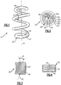
- Figure 1 shows an example composite coil spring 20 that may be used in a suspension system of a vehicle, for example. It is to be understood, however, that the composite coil spring 20 is not limited to such uses.
- the composite coil spring 20 may be helical or alternatively have a different coil shape.
- a "coil” or variations thereof means a body that curves continuously around a fixed linear axis, such as axis A in Figure 1 .
- the composite coil spring 20 is strong and lightweight and therefore provides a weight reduction for the replacement of metallic coil springs in vehicles or other applications, which can improve fuel mileage.
- the composite coil spring 20 includes a coil body 22 that extends along a coiled axis 24 between terminal ends 26/28.
- the coil body 22 includes a polymer material 30 and a plurality of fiber layers 32 impregnated with the polymer material 30.
- the polymer material 30 can be epoxy or polyester.
- the polymer material can be a different composition of organic polymer than epoxy or polyester.
- a "layer" has a uniform radial thickness around the entire layer circumference.
- Each of the fiber layers 32 includes a plurality of fibers 34 that are arranged at an oblique fiber angle ⁇ (alpha) to the coiled axis 24.
- the fibers 34 are or include metallic fibers, ceramic fibers, organic fibers or combinations thereof.
- the fibers 34 are glass fibers, carbon fibers, aramid fibers or combinations thereof.
- the fibers 34 of the fiber layers 32 are not shown in Figure 2 .
- the fibers 34 of each of the fiber layers 32 extend around the coiled axis 24 at the selected oblique fiber angle ⁇ .
- the oblique fiber angle ⁇ is +/- 20-54° to provide the coil body 22 with a high degree of strength.
- the fiber layers 32 may alternate in fiber orientation such that the oblique fiber angle ⁇ of any one of the fiber layers 32 is also oblique to one or two directly neighboring ones of the fiber layers 32 ( Figure 4 ) at each location along the coiled axis 24.
- the fiber layers 32 are arranged at different radial distances, as shown at 36, from the coiled axis 24.
- the radial distances 36 are the distances between the coiled axis 24 and the radially inner surface of the fiber layers 32.
- the plurality of fiber layers 32 includes fiber layers 32a-f.
- Fiber layer 32a is an innermost layer with regard to radial distance from the coiled axis 24 and fiber layer 32f is an outermost layer with regard to radial distance from the coiled axis 24.
- the terms “innermost” and “outermost” mean that there are no other fiber layers located radially inwards or radially outwards of, respectively, of the innermost fiber layer 32a and the outermost fiber layer 32f.
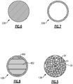
- the fiber layers 32 are wound around a core 38.
- the core 38 can be a fibrous core 138 impregnated with the polymer 30 ( Figure 5 ).
- the fibers 34 of the fibrous core 138 can extend substantially parallel to the coiled axis 24, within +/- 20°.
- the core 38 can be a solid, non-fibrous core 238 ( Figure 6 ) that is polymeric or metallic.
- the core 38 can be a hollow tube 338 ( Figure 7 ) or a tube 438 ( Figure 8 ) that has an interior cavity 450 that includes a filler material 452.
- the filler material 452 can be different in composition from the material of the tube 448, such as two different polymer compositions, metallic compositions or combinations.
- the material and diameter of the core 38 can be selected such that the core 38 is flexible to allow formation of the desired coil shape.
- the core 38 can be or can include a shape memory material that changes shape in response to changes in temperature relative to a temperature threshold, to aid in formation of the coil shape.
- Each of the fiber layers 32 and, optionally, the fibrous core 138 includes a number of the fibers 34 that is a product of a common base number of fibers multiplied by a positive non-zero integer selected from a set of positive non-zero integers.
- the common base number is a predetermined number that is equal for each of the fiber layers 32 and the fibrous core 138.
- the positive non-zero integer of at least one of the fiber layers 32 is different from the positive non-zero integer of the fibrous core 38 and can also be different from at least one other of the fiber layers 32.
- Using the number of fibers 34 that is a product of the common base number of fibers multiplied by a positive non-zero integer selected from the set of positive non-zero integers facilitates manufacturing and also provides a desirable strength profile.
- the fibrous core 138 and the outermost fiber layer 32f have equal positive non-zero integers.
- the fiber layers 32a-e are intermediate layers (multiple first fiber layers) that are arranged radially between the fibrous core 138 and the outermost fiber layer 32f.
- the intermediate fiber layers 32a-e have equal positive non-zero integers and these integers are non-equal to the integers of the fibrous core 138 and the outermost fiber layer 32f. That is, at least two of the fiber layers 32 have different positive non-zero integers and at least one of the fiber layers 32 has a different positive non-zero integer than the fibrous core 138.
- the positive non-zero integer of the intermediate fiber layers 32a-e is less than the positive non-zero integer of the fibrous core 138 and the outermost fiber layer 32f, which can be equal.
- the intermediate fiber layers 32a-e each have a number of fibers N1 and the fibrous core and the outermost fiber layer 32f each have a number of fibers N2 that is different from the number of fibers N1 by a multiplier factor.
- the positive multiplier factor is 2-20.
- the number of fibers 34 in any one of the fiber layers 32 and the fibrous core 138 corresponds to the number of fibers 34 in one or more fiber rovings that are used to fabricate the fiber layers 32 and fibrous core 138 of the coil body 22.
- a single fiber roving may have 2,000 individual fibers and 11 rovings that establish the common base number of fibers, which in this example would be 22,000 fibers.
- the actual number of fibers 34 in any one of the fiber layers 32 and fibrous core 138 would be 22,000 fibers multiplied by the selected positive non-zero integer for that individual fiber layer 32.
- the set of positive non-zero integers is between 1 and 20.
- the number of fibers 34 per roving and the number of rovings used to determine the common base number of fibers can be varied. In a further example, between 4 and 60 rovings may be used, with either 2,000 or 4,000 fibers per roving.
- the number of fibers 34 in any one of the fiber layers 32 or the fibrous core 138 may practically vary somewhat because a small number of fibers 34 may break during fabrication and/or rovings may vary from a nominal fiber count.
- the equivalence can be based upon the nominal numbers of fibers.
- the difference can be based upon the nominal numbers of fibers.
- the positive non-zero integer of the intermediate layers 32a-e is 1, and the positive non-zero integers of each of the fibrous core 138 and the outermost fiber layer 32f is 3.
- the positive non-zero integers of at least two of the fiber layers 32 differ by at least 2, and the positive non-zero integer multiplier factor is 3.
- a method of fabricating the composite coil spring 20 includes forming the coil body 22 as described above. For example, for a given fiber layer 32 or the optional fibrous core 138, an appropriate number of spools or fiber rovings corresponding to the selected positive non-zero integer for that fiber layer 32 or the fibrous core 138 provide the fibers 34 through a guide device and a reservoir of the polymer resin material to impregnate the fibers 34. The impregnated fibers are then wound around the core 38 using winding equipment. This process is repeated for each of the fiber layers 32 until a desired number of fiber layers 32 are wound.
- the resulting resin-impregnated fiber structure is then removed from the winding equipment.
- the structure is arranged into a coil groove of a mandrel.
- the coil groove corresponds to the desired end shape of the composite coil spring 20.
- the mandrel and structure are then heated in a furnace to cure the resin and thereby form the permanent shape of the composite coil spring 20.
- the heating temperature and time depend upon the type of polymer material selected and, given this description, one of ordinary skill in the art will be able to determine a suitable heating temperature and time to meet their particular needs.
- the mandrel is then removed by mechanical or other means, leaving the finished or near finished composite coil spring 20.
Landscapes
- Engineering & Computer Science (AREA)
- General Engineering & Computer Science (AREA)
- Mechanical Engineering (AREA)
- Chemical & Material Sciences (AREA)
- Composite Materials (AREA)
- Springs (AREA)
Claims (15)
- Verbundstoff-Schraubenfeder, Folgendes beinhaltend:
einen Spiralkörper (20), welcher sich entlang einer Spiralachse (24) erstreckt, wobei der Spiralkörper einen Kern (38) und eine Vielzahl von Faserschichten (32) besitzt, welche mit einem Polymermaterial (30) imprägniert sind, wobei die Vielzahl von Faserschichten (32) um den Kern (38) herum in unterschiedlichen radialen Abständen (36) von der Spiralachse (24) angeordnet ist, wobei jede der Vielzahl von Faserschichten (32) sich um die Spiralachse in einem schrägen Faserwinkel (a) zur Spiralachse (24) erstreckt, wobei jede der Vielzahl von Faserschichten (32) eine Anzahl von Fasern (34) enthält, welche ein Produkt einer gemeinsamen Basisanzahl von Fasern (34) ist, multipliziert mit einer positiven Ganzzahl ungleich null aus einer Reihe von positiven Ganzzahlen ungleich null, und wobei die positive Ganzzahl ungleich null von mindestens einer der Vielzahl von Faserschichten (32) sich von der positiven Ganzzahl ungleich null von mindestens einer anderen der Vielzahl von Faserschichten (32) unterscheidet, wobei die gemeinsame Basisanzahl von Fasern durch eine Anzahl an Fasern in einem Faserbündel und durch eine Anzahl von verwendeten Faserbündeln festgelegt wird. - Verbundstoff-Schraubenfeder nach Anspruch 1, bei welcher:
der Spiralkörper einen faserigen Kern (138) enthält; die Vielzahl von Faserschichten (32) um den faserigen Kern (138) herum in unterschiedlichen radialen Abständen (36) von der Spiralachse (24) angeordnet ist; und bei welcher jede der Vielzahl von Faserschichten (32) sich um die Spiralachse (24) in einem schrägen Winkel (α) zur Spiralachse erstreckt, wobei jede der Vielzahl von Faserschichten (32) und der faserige Kern (138) eine Anzahl von Fasern (34) enthalten, welche ein Produkt einer gemeinsamen Basisanzahl von Fasern (34) ist, multipliziert mit einer positiven Ganzzahl ungleich null aus einer Reihe von positiven Ganzzahlen ungleich null, und wobei die positive Ganzzahl ungleich null von mindestens einer der Vielzahl von Faserschichten (32) sich von der positiven Ganzzahl ungleich null des faserigen Kerns (138) unterscheidet. - Verbundstoff-Schraubenfeder nach Anspruch 1, bei welcher die Reihe von positiven Ganzzahlen ungleich Null 1 bis 20 lautet.
- Verbundstoff-Schraubenfeder nach Anspruch 1 oder 2, bei welcher der schräge Winkel (α) +/- 20-54° beträgt.
- Verbundstoff-Schraubenfeder nach Anspruch 1, bei welcher in Bezug auf die Spiralachse eine innerste Schicht (32a) der Vielzahl von Faserschichten (32) und eine äußerste Schicht (32f) der Vielzahl von Faserschichten (32) gleiche positive Ganzzahlen ungleich null besitzen.
- Verbundstoff-Schraubenfeder nach Anspruch 1, bei welcher der Kern (38) ein faseriger Kern (138) ist und Zwischenfaserschichten der Vielzahl von Faserschichten (32) gleiche positive Ganzzahlen ungleich null besitzen, wobei die Zwischenfaserschichten (32) in Bezug auf die Spiralachse (24) zwischen dem faserigen Kern (138) und einer äußersten Faserschicht (32f) der Vielzahl von Faserschichten (32) angeordnet sind, oder
wobei der Kern (38) ein faseriger Kern (138) ist und eine Anzahl von Fasern (34) enthält, welche ein Produkt einer gemeinsamen Basisanzahl von Fasern (34) ist, multipliziert mit einer positiven Ganzzahl ungleich null aus der Reihe von positiven Ganzzahlen ungleich null, und wobei die positive Ganzzahl ungleich null von mindestens einer der Vielzahl von Faserschichten (32) sich von der positiven Ganzzahl ungleich null des faserigen Kerns (138) unterscheidet. - Verbundstoff-Schraubenfeder nach Anspruch 1, bei welcher die positiven Ganzzahlen ungleich null von mindestens zwei der Vielzahl von Faserschichten (32), welche unterschiedlich sind, sich um mindestens 1 unterscheiden.
- Verbundstoff-Schraubenfeder nach Anspruch 1 oder 2, bei welcher der schräge Faserwinkel (a) einer jeden der Vielzahl von Faserschichten (32) ebenfalls schräg zu mindestens einer direkt benachbarten Faserschicht der Vielzahl von Faserschichten (32) ist.
- Verbundstoff-Schraubenfeder nach Anspruch 1, bei welcher das Polymermaterial (30) Epoxid enthält, oder
bei welcher das Polymermaterial (30) Polyester enthält. - Verbundstoff-Schraubenfeder nach Anspruch 1, bei welcher die Vielzahl von Faserschichten (32) aus der Gruppe gewählt sind, bestehend aus Glasfasern, Kohlenstofffasern, Aramidfasern und Kombinationen hieraus, oder
bei welcher die Vielzahl von Faserschichten (32) aus der Gruppe gewählt sind, bestehend aus Metallfasern, Keramikfasern, organischen Fasern und Kombinationen hieraus. - Verbundstoff-Schraubenfeder nach Anspruch 1, bei welcher der Kern (38) ein fester Kern (238) ist, wahlweise
bei welcher der Feststoffkern (238) aus Polymer besteht, oder
bei welcher der Feststoffkern (238) aus Metall besteht. - Verbundstoff-Schraubenfeder nach Anspruch 1, bei welcher der Kern (38) ein Material mit Formgedächtnis enthält, oder
bei welcher der Kern (338) eine hohle Röhre ist, oder
bei welcher der Kern (438) eine Röhre ist, welche einen inneren Hohlraum (450) definiert, und der innere Hohlraum ein Füllermaterial (452) darin enthält. - Verbundstoff-Schraubenfeder nach Anspruch 2, bei welcher die Vielzahl von Faserschichten (32) mindestens eine erste Faserschicht (32a) und mindestens eine zweite Faserschicht (32b) enthält, wobei die erste Faserschicht (32a) eine Anzahl N1 von Fasern und die zweite Faserschicht (32b) eine Anzahl N2 von Fasern besitzt, welche sich von der Anzahl N1 von Fasern unterscheidet.
- Verbundstoff-Schraubenfeder nach Anspruch 13, bei welcher die Anzahl N2 von Fasern sich von der Anzahl N1 von Fasern um einen positiven Multiplikationsfaktor von 2 bis 20 unterscheidet, oder
bei welcher in Bezug auf die Spiralachse (24) die zweite Faserschicht eine äußerste Schicht (32f) und die erste Faserschicht (32a) eine Zwischenfaserschicht (32) ist, welche zwischen der äußersten Schicht und dem faserigen Kern (138) angeordnet ist. - Verfahren zum Herstellen einer Verbundstoff-Schraubenfeder, wobei das Verfahren Folgendes beinhaltet:
Bilden eines Spiralkörpers (20) entlang einer Spiralachse (24) von einem Kern (38) und eine Vielzahl von Faserschichten (32), welche mit einem Polymermaterial (30) imprägniert sind, wobei die Vielzahl von Faserschichten (32) um den Kern (38) herum in unterschiedlichen radialen Abständen (36) von der Spiralachse angeordnet ist, wobei jede der Vielzahl von Faserschichten (32) sich um die Spiralachse (24) in einem schrägen Faserwinkel (a) zur Spiralachse (24) erstreckt, wobei jede der Vielzahl von Faserschichten (32) eine Anzahl von Fasern (34) enthält, welche ein Produkt einer gemeinsamen Basisanzahl von Fasern (34) ist, multipliziert mit einer positiven Ganzzahl ungleich null aus einer Reihe von positiven Ganzzahlen ungleich null, und wobei die positiven Ganzzahlen ungleich null von mindestens einer der Vielzahl von Faserschichten (32) sich von der positiven Ganzzahl ungleich null von mindestens einer anderen der Vielzahl von Faserschichten (32) unterscheiden, wobei die gemeinsame Basisanzahl von Fasern durch eine Anzahl an Fasern in einem Faserbündel und durch eine Anzahl an verwendeten Faserbündeln festgelegt wird.
Priority Applications (2)
| Application Number | Priority Date | Filing Date | Title |
|---|---|---|---|
| PL12753316T PL2875254T3 (pl) | 2012-07-18 | 2012-08-17 | Kompozytowa sprężyna zwojowa |
| EP18174291.7A EP3388708B1 (de) | 2012-07-18 | 2012-08-17 | Zusammengesetzte schraubenfeder |
Applications Claiming Priority (2)
| Application Number | Priority Date | Filing Date | Title |
|---|---|---|---|
| US13/551,977 US8857801B2 (en) | 2012-07-18 | 2012-07-18 | Composite coil spring |
| PCT/US2012/051318 WO2014014481A1 (en) | 2012-07-18 | 2012-08-17 | Composite coil spring |
Related Child Applications (1)
| Application Number | Title | Priority Date | Filing Date |
|---|---|---|---|
| EP18174291.7A Division EP3388708B1 (de) | 2012-07-18 | 2012-08-17 | Zusammengesetzte schraubenfeder |
Publications (2)
| Publication Number | Publication Date |
|---|---|
| EP2875254A1 EP2875254A1 (de) | 2015-05-27 |
| EP2875254B1 true EP2875254B1 (de) | 2018-05-30 |
Family
ID=46759074
Family Applications (2)
| Application Number | Title | Priority Date | Filing Date |
|---|---|---|---|
| EP12753316.4A Active EP2875254B1 (de) | 2012-07-18 | 2012-08-17 | Zusammengesetzte schraubenfeder |
| EP18174291.7A Active EP3388708B1 (de) | 2012-07-18 | 2012-08-17 | Zusammengesetzte schraubenfeder |
Family Applications After (1)
| Application Number | Title | Priority Date | Filing Date |
|---|---|---|---|
| EP18174291.7A Active EP3388708B1 (de) | 2012-07-18 | 2012-08-17 | Zusammengesetzte schraubenfeder |
Country Status (11)
| Country | Link |
|---|---|
| US (4) | US8857801B2 (de) |
| EP (2) | EP2875254B1 (de) |
| JP (1) | JP6017689B2 (de) |
| CN (2) | CN107255130B (de) |
| CA (1) | CA2877488C (de) |
| ES (2) | ES2681884T3 (de) |
| HK (1) | HK1254597A1 (de) |
| HU (2) | HUE059727T2 (de) |
| MX (1) | MX2015000753A (de) |
| PL (1) | PL2875254T3 (de) |
| WO (1) | WO2014014481A1 (de) |
Families Citing this family (17)
| Publication number | Priority date | Publication date | Assignee | Title |
|---|---|---|---|---|
| JP5735826B2 (ja) * | 2011-03-10 | 2015-06-17 | 日本発條株式会社 | 繊維強化プラスチック製ばね |
| US8857801B2 (en) * | 2012-07-18 | 2014-10-14 | Mssc Us | Composite coil spring |
| DE102013224442B4 (de) * | 2013-11-28 | 2022-05-05 | Fraunhofer-Gesellschaft zur Förderung der angewandten Forschung e.V. | Federelement |
| DE102014207151A1 (de) | 2014-04-14 | 2015-10-15 | Leichtbau-Zentrum Sachsen Gmbh | Torsionsbelastetes stabförmiges Bauteil |
| DE102014211096A1 (de) | 2014-06-11 | 2015-12-17 | Thyssenkrupp Ag | Torsionsbelastetes stabförmiges Bauteil mit unterschiedlichen Faserverstärkungen für Zug- und Druckbelastung |
| DE102014115619A1 (de) * | 2014-10-28 | 2016-04-28 | Dr. Ing. H.C. F. Porsche Aktiengesellschaft | Spiralfeder und zugehöriges Herstellungsverfahren |
| CN109073020A (zh) | 2016-03-23 | 2018-12-21 | 日本发条株式会社 | 螺旋弹簧 |
| DE102016119027A1 (de) * | 2016-10-07 | 2018-04-12 | Chr. Mayr Gmbh + Co. Kg | Elektromagnetische Bremse mit einer steuerbaren Ankerscheibenbewegung |
| CN110121407A (zh) * | 2017-01-10 | 2019-08-13 | 巴斯夫欧洲公司 | 线材及制备线材的方法 |
| EP3673184A4 (de) * | 2017-08-24 | 2021-05-05 | Ressorts Liberte Inc. | Schraubenfeder und herstellungsverfahren dafür |
| US11617670B2 (en) | 2018-01-10 | 2023-04-04 | Grd Innovations, Llc | Variable radius spring assembly |
| DE102018203452B3 (de) * | 2018-03-07 | 2019-09-12 | Audi Ag | Radaufhängung für ein Kraftfahrzeug, Kraftfahrzeug sowie Verfahren zum Betreiben einer solchen Radaufhängung |
| WO2019219694A1 (de) * | 2018-05-14 | 2019-11-21 | Basf Polyurethanes Gmbh | Verfahren zur herstellung einer composite-feder, und selbige |
| FR3090461B1 (fr) * | 2018-12-20 | 2021-12-03 | S Ara Composite | Corde composite |
| EP3918222A1 (de) * | 2019-01-30 | 2021-12-08 | Driv Automotive Inc. | Suspension mit elektrisch kontrollierbarem material |
| FR3097794A1 (fr) * | 2019-06-28 | 2021-01-01 | Sogefi Suspensions | Outil de confinement pour fabriquer un corps composite |
| US20220170525A1 (en) * | 2019-07-01 | 2022-06-02 | Mitsubishi Steel Mfg. Co., Ltd. | Composite coil spring with carbon and glass fiber layers |
Family Cites Families (43)
| Publication number | Priority date | Publication date | Assignee | Title |
|---|---|---|---|---|
| US2852424A (en) | 1957-04-30 | 1958-09-16 | Frank W Reinhart | Reinforced plastic springs |
| US3378426A (en) | 1964-10-05 | 1968-04-16 | Koppers Co Inc | Apparatus for forming continuous helical coils of resin bonded glass fibers |
| US3321200A (en) | 1965-01-13 | 1967-05-23 | Gen Motors Corp | Reinforced plastic bellows spring |
| JPS5234161A (en) * | 1975-09-10 | 1977-03-15 | Sumitomo Electric Ind Ltd | Coil spring of reinforced plastic material |
| JPS5236250A (en) | 1975-09-12 | 1977-03-19 | Sumitomo Electric Ind Ltd | Tempered plastic coil spring |
| US4260143A (en) | 1979-01-15 | 1981-04-07 | Celanese Corporation | Carbon fiber reinforced composite coil spring |
| US4380483A (en) | 1979-01-15 | 1983-04-19 | Celanese Corporation | Process for forming improved carbon fiber reinforced composite coil spring |
| CA1154042A (en) * | 1979-07-12 | 1983-09-20 | Frank H. Doyal | Fiber-reinforced tubular spring |
| US4468014A (en) * | 1980-09-15 | 1984-08-28 | Paccar, Inc. | Composite leaf spring |
| US4765602A (en) | 1980-12-28 | 1988-08-23 | The Boeing Company | Composite coil spring |
| US4434121A (en) | 1981-10-01 | 1984-02-28 | Audi Nsu Auto Union Aktiengesellschaft | Method for production of a helical spring from a fiber-reinforced plastic |
| US4473217A (en) | 1982-01-07 | 1984-09-25 | Kato Hatsujo Kaisha, Limited | Fiber-reinforced resin coil spring and method of manufacturing the same |
| US4464216A (en) | 1982-03-26 | 1984-08-07 | Hercules Incorporated | Composite negator springs |
| US4817921A (en) | 1984-12-12 | 1989-04-04 | The Paton Corporation | Composite spring |
| DE3506037C1 (de) | 1985-02-21 | 1986-01-16 | Deutsche Forschungs- und Versuchsanstalt für Luft- und Raumfahrt e.V., 5300 Bonn | Schraubenfeder sowie Verfahren zu deren Herstellung |
| US5098493A (en) | 1986-11-10 | 1992-03-24 | Tayco Developments, Inc. | Method of fabricating springs formed of rope pressure-saturated or impregnated with binder |
| US4991827A (en) | 1986-11-10 | 1991-02-12 | Tayco Developments, Inc. | Springs formed of rope pressure-saturated or impregnated with binder |
| US4779850A (en) | 1987-02-13 | 1988-10-25 | The Paton Corporation | Composite spring with suction seal |
| JPH0773888B2 (ja) * | 1987-05-28 | 1995-08-09 | 住友電気工業株式会社 | 強化プラスチック製ばね用素材及びその製造方法 |
| US5146835A (en) | 1988-02-02 | 1992-09-15 | E. I. Dupont De Nemours And Company | In-line consolidation of braided structures |
| US5320696A (en) | 1988-02-02 | 1994-06-14 | E. I. Du Pont De Nemours And Company | In-line consolidation of braided structures |
| US4976812A (en) | 1988-02-02 | 1990-12-11 | E. I. Du Pont De Nemours And Company | In-line consolidation of braided structures |
| US4889327B1 (en) | 1988-03-15 | 1994-12-20 | Harris Trust And Savings Bank | Multiple-strand torsion spring |
| JPH01269736A (ja) * | 1988-04-22 | 1989-10-27 | Mitsubishi Heavy Ind Ltd | つる巻きばね |
| US5326524A (en) | 1990-03-23 | 1994-07-05 | Phillips Petroleum Company | Method of making plastic rods |
| JPH04136530A (ja) * | 1990-09-27 | 1992-05-11 | Toyama Pref Gov | Frpコイルばね及びその製造方法 |
| JP3009311B2 (ja) | 1993-08-04 | 2000-02-14 | 東邦レーヨン株式会社 | 繊維強化樹脂製コイルスプリングおよびその製造方法 |
| US5468327A (en) | 1994-01-24 | 1995-11-21 | University Of Massachusetts Lowell | Method and device for continuous formation of braid reinforced thermoplastic structural and flexible members |
| US5549370A (en) | 1994-11-07 | 1996-08-27 | Folsom; Mark F. | Fiber-reinforced plastic springs with helical fiber wind |
| US5603490A (en) | 1994-11-07 | 1997-02-18 | Folsom; Mark F. | Fiber-reinforced plastic springs with helical fiber wind |
| JPH109315A (ja) * | 1996-06-25 | 1998-01-13 | Piolax Inc | 感温コイルばね及びそれを用いた調節弁 |
| US5988612A (en) | 1997-08-07 | 1999-11-23 | Bertelson; Peter C. | Composite helical springs and process of manufacture |
| US6454251B1 (en) | 2000-05-01 | 2002-09-24 | John C. Fish | Composite cord assembly |
| US6612556B2 (en) | 2001-04-30 | 2003-09-02 | Cornell Research Foundation, Inc. | Multihelical composite spring |
| US7044458B2 (en) | 2001-04-30 | 2006-05-16 | Maclean-Fogg Company | Stabilizer bar |
| TW565647B (en) | 2001-08-17 | 2003-12-11 | Univ Brigham Young | Method and apparatus for fabricating complex, composite structures from continuous fibers |
| JP4136530B2 (ja) | 2002-08-12 | 2008-08-20 | 日本電産サンキョー株式会社 | ダンパー装置 |
| US7168117B2 (en) | 2003-02-19 | 2007-01-30 | Dreamwell Ltd. | Multi-stranded coil spring |
| JP2006226327A (ja) | 2005-02-15 | 2006-08-31 | Kyoto Institute Of Technology | Frp製コイルばね及びその生産方法 |
| JP2007064389A (ja) * | 2005-08-31 | 2007-03-15 | Mizuno Technics Kk | 繊維強化樹脂製コイルバネおよびその製造方法 |
| CN100553953C (zh) * | 2006-03-24 | 2009-10-28 | 徐献忠 | 玻璃钢复合材料板弹簧的制造方法 |
| US7857294B2 (en) | 2008-03-28 | 2010-12-28 | Spencer Composites Corporation | Composite springs and methods of manufacture |
| US8857801B2 (en) * | 2012-07-18 | 2014-10-14 | Mssc Us | Composite coil spring |
-
2012
- 2012-07-18 US US13/551,977 patent/US8857801B2/en active Active
- 2012-08-17 JP JP2015523064A patent/JP6017689B2/ja active Active
- 2012-08-17 PL PL12753316T patent/PL2875254T3/pl unknown
- 2012-08-17 EP EP12753316.4A patent/EP2875254B1/de active Active
- 2012-08-17 WO PCT/US2012/051318 patent/WO2014014481A1/en active Application Filing
- 2012-08-17 CA CA2877488A patent/CA2877488C/en active Active
- 2012-08-17 HU HUE18174291A patent/HUE059727T2/hu unknown
- 2012-08-17 EP EP18174291.7A patent/EP3388708B1/de active Active
- 2012-08-17 ES ES12753316.4T patent/ES2681884T3/es active Active
- 2012-08-17 CN CN201710497524.XA patent/CN107255130B/zh active Active
- 2012-08-17 ES ES18174291T patent/ES2915053T3/es active Active
- 2012-08-17 MX MX2015000753A patent/MX2015000753A/es unknown
- 2012-08-17 CN CN201280074995.5A patent/CN104583637B/zh active Active
- 2012-08-17 US US14/415,266 patent/US9677637B2/en active Active
- 2012-08-17 HU HUE12753316A patent/HUE039715T2/hu unknown
-
2017
- 2017-05-02 US US15/584,414 patent/US9982734B2/en active Active
-
2018
- 2018-04-27 US US15/964,652 patent/US10385940B2/en active Active
- 2018-10-23 HK HK18113536.4A patent/HK1254597A1/zh unknown
Non-Patent Citations (1)
| Title |
|---|
| None * |
Also Published As
| Publication number | Publication date |
|---|---|
| PL2875254T3 (pl) | 2018-10-31 |
| CN104583637B (zh) | 2017-07-25 |
| EP3388708A1 (de) | 2018-10-17 |
| US20180245651A1 (en) | 2018-08-30 |
| US20170234392A1 (en) | 2017-08-17 |
| HUE059727T2 (hu) | 2022-12-28 |
| CA2877488C (en) | 2019-01-29 |
| US20140021666A1 (en) | 2014-01-23 |
| US20150204404A1 (en) | 2015-07-23 |
| EP3388708B1 (de) | 2022-04-27 |
| US10385940B2 (en) | 2019-08-20 |
| CN107255130A (zh) | 2017-10-17 |
| US9677637B2 (en) | 2017-06-13 |
| ES2915053T3 (es) | 2022-06-20 |
| ES2681884T3 (es) | 2018-09-17 |
| HK1254597A1 (zh) | 2019-07-26 |
| HUE039715T2 (hu) | 2019-02-28 |
| US9982734B2 (en) | 2018-05-29 |
| JP2015526661A (ja) | 2015-09-10 |
| CN107255130B (zh) | 2019-09-20 |
| MX2015000753A (es) | 2015-09-10 |
| CA2877488A1 (en) | 2014-01-23 |
| JP6017689B2 (ja) | 2016-11-02 |
| WO2014014481A1 (en) | 2014-01-23 |
| CN104583637A (zh) | 2015-04-29 |
| US8857801B2 (en) | 2014-10-14 |
| EP2875254A1 (de) | 2015-05-27 |
Similar Documents
| Publication | Publication Date | Title |
|---|---|---|
| EP2875254B1 (de) | Zusammengesetzte schraubenfeder | |
| JP2015526661A5 (de) | ||
| US10767720B2 (en) | Method for leaf springs made of fiber-reinforced plastic with integrated eye bushings, and leaf spring made of fiber-reinforced plastic | |
| US20220065400A1 (en) | Tank production method and tank | |
| CN113646556B (zh) | 具有碳纤维和玻璃纤维层的复合线圈弹簧 | |
| CN108350968B (zh) | 弹性部件用线材以及弹性部件 | |
| JP2017140809A (ja) | タンクの製造方法 | |
| JP2017082967A (ja) | コイルばね用線材およびコイルばね | |
| EP2563571B1 (de) | Verfahren zur herstellung eines verbundrings, verbundring, verwendung des rings für eine dichtungsanordnung und dichtungsanordnung | |
| JP2007216558A (ja) | 繊維強化合成樹脂ボビン | |
| JP2007064389A (ja) | 繊維強化樹脂製コイルバネおよびその製造方法 | |
| WO2017073771A1 (ja) | 弾性部材用線材および弾性部材 | |
| KR102391001B1 (ko) | 복합재 코일 스프링 및 그 제조방법 |
Legal Events
| Date | Code | Title | Description |
|---|---|---|---|
| PUAI | Public reference made under article 153(3) epc to a published international application that has entered the european phase |
Free format text: ORIGINAL CODE: 0009012 |
|
| 17P | Request for examination filed |
Effective date: 20150107 |
|
| AK | Designated contracting states |
Kind code of ref document: A1 Designated state(s): AL AT BE BG CH CY CZ DE DK EE ES FI FR GB GR HR HU IE IS IT LI LT LU LV MC MK MT NL NO PL PT RO RS SE SI SK SM TR |
|
| AX | Request for extension of the european patent |
Extension state: BA ME |
|
| RAP1 | Party data changed (applicant data changed or rights of an application transferred) |
Owner name: MITSUBISHI STEEL MFG. CO., LTD. |
|
| DAX | Request for extension of the european patent (deleted) | ||
| STAA | Information on the status of an ep patent application or granted ep patent |
Free format text: STATUS: EXAMINATION IS IN PROGRESS |
|
| 17Q | First examination report despatched |
Effective date: 20170428 |
|
| REG | Reference to a national code |
Ref country code: DE Ref legal event code: R079 Ref document number: 602012046913 Country of ref document: DE Free format text: PREVIOUS MAIN CLASS: F16F0001366000 Ipc: B29L0031000000 |
|
| GRAP | Despatch of communication of intention to grant a patent |
Free format text: ORIGINAL CODE: EPIDOSNIGR1 |
|
| STAA | Information on the status of an ep patent application or granted ep patent |
Free format text: STATUS: GRANT OF PATENT IS INTENDED |
|
| RIC1 | Information provided on ipc code assigned before grant |
Ipc: B29C 70/08 20060101ALI20171027BHEP Ipc: B29L 31/00 20060101AFI20171027BHEP Ipc: B29K 309/08 20060101ALI20171027BHEP Ipc: B29K 307/04 20060101ALI20171027BHEP Ipc: B29K 277/00 20060101ALI20171027BHEP Ipc: B60G 11/14 20060101ALI20171027BHEP Ipc: F16F 1/366 20060101ALI20171027BHEP |
|
| INTG | Intention to grant announced |
Effective date: 20171201 |
|
| GRAS | Grant fee paid |
Free format text: ORIGINAL CODE: EPIDOSNIGR3 |
|
| GRAJ | Information related to disapproval of communication of intention to grant by the applicant or resumption of examination proceedings by the epo deleted |
Free format text: ORIGINAL CODE: EPIDOSDIGR1 |
|
| GRAL | Information related to payment of fee for publishing/printing deleted |
Free format text: ORIGINAL CODE: EPIDOSDIGR3 |
|
| STAA | Information on the status of an ep patent application or granted ep patent |
Free format text: STATUS: EXAMINATION IS IN PROGRESS |
|
| GRAJ | Information related to disapproval of communication of intention to grant by the applicant or resumption of examination proceedings by the epo deleted |
Free format text: ORIGINAL CODE: EPIDOSDIGR1 |
|
| GRAP | Despatch of communication of intention to grant a patent |
Free format text: ORIGINAL CODE: EPIDOSNIGR1 |
|
| INTC | Intention to grant announced (deleted) | ||
| GRAR | Information related to intention to grant a patent recorded |
Free format text: ORIGINAL CODE: EPIDOSNIGR71 |
|
| STAA | Information on the status of an ep patent application or granted ep patent |
Free format text: STATUS: GRANT OF PATENT IS INTENDED |
|
| GRAA | (expected) grant |
Free format text: ORIGINAL CODE: 0009210 |
|
| STAA | Information on the status of an ep patent application or granted ep patent |
Free format text: STATUS: THE PATENT HAS BEEN GRANTED |
|
| AK | Designated contracting states |
Kind code of ref document: B1 Designated state(s): AL AT BE BG CH CY CZ DE DK EE ES FI FR GB GR HR HU IE IS IT LI LT LU LV MC MK MT NL NO PL PT RO RS SE SI SK SM TR |
|
| INTG | Intention to grant announced |
Effective date: 20180423 |
|
| REG | Reference to a national code |
Ref country code: GB Ref legal event code: FG4D |
|
| REG | Reference to a national code |
Ref country code: CH Ref legal event code: EP |
|
| REG | Reference to a national code |
Ref country code: AT Ref legal event code: REF Ref document number: 1003183 Country of ref document: AT Kind code of ref document: T Effective date: 20180615 |
|
| REG | Reference to a national code |
Ref country code: IE Ref legal event code: FG4D |
|
| REG | Reference to a national code |
Ref country code: DE Ref legal event code: R096 Ref document number: 602012046913 Country of ref document: DE |
|
| REG | Reference to a national code |
Ref country code: FR Ref legal event code: PLFP Year of fee payment: 7 |
|
| REG | Reference to a national code |
Ref country code: ES Ref legal event code: FG2A Ref document number: 2681884 Country of ref document: ES Kind code of ref document: T3 Effective date: 20180917 |
|
| REG | Reference to a national code |
Ref country code: NL Ref legal event code: MP Effective date: 20180530 |
|
| REG | Reference to a national code |
Ref country code: LT Ref legal event code: MG4D |
|
| PG25 | Lapsed in a contracting state [announced via postgrant information from national office to epo] |
Ref country code: NO Free format text: LAPSE BECAUSE OF FAILURE TO SUBMIT A TRANSLATION OF THE DESCRIPTION OR TO PAY THE FEE WITHIN THE PRESCRIBED TIME-LIMIT Effective date: 20180830 Ref country code: LT Free format text: LAPSE BECAUSE OF FAILURE TO SUBMIT A TRANSLATION OF THE DESCRIPTION OR TO PAY THE FEE WITHIN THE PRESCRIBED TIME-LIMIT Effective date: 20180530 Ref country code: FI Free format text: LAPSE BECAUSE OF FAILURE TO SUBMIT A TRANSLATION OF THE DESCRIPTION OR TO PAY THE FEE WITHIN THE PRESCRIBED TIME-LIMIT Effective date: 20180530 Ref country code: BG Free format text: LAPSE BECAUSE OF FAILURE TO SUBMIT A TRANSLATION OF THE DESCRIPTION OR TO PAY THE FEE WITHIN THE PRESCRIBED TIME-LIMIT Effective date: 20180830 Ref country code: CY Free format text: LAPSE BECAUSE OF FAILURE TO SUBMIT A TRANSLATION OF THE DESCRIPTION OR TO PAY THE FEE WITHIN THE PRESCRIBED TIME-LIMIT Effective date: 20180530 Ref country code: SE Free format text: LAPSE BECAUSE OF FAILURE TO SUBMIT A TRANSLATION OF THE DESCRIPTION OR TO PAY THE FEE WITHIN THE PRESCRIBED TIME-LIMIT Effective date: 20180530 |
|
| PG25 | Lapsed in a contracting state [announced via postgrant information from national office to epo] |
Ref country code: HR Free format text: LAPSE BECAUSE OF FAILURE TO SUBMIT A TRANSLATION OF THE DESCRIPTION OR TO PAY THE FEE WITHIN THE PRESCRIBED TIME-LIMIT Effective date: 20180530 Ref country code: LV Free format text: LAPSE BECAUSE OF FAILURE TO SUBMIT A TRANSLATION OF THE DESCRIPTION OR TO PAY THE FEE WITHIN THE PRESCRIBED TIME-LIMIT Effective date: 20180530 Ref country code: GR Free format text: LAPSE BECAUSE OF FAILURE TO SUBMIT A TRANSLATION OF THE DESCRIPTION OR TO PAY THE FEE WITHIN THE PRESCRIBED TIME-LIMIT Effective date: 20180831 Ref country code: RS Free format text: LAPSE BECAUSE OF FAILURE TO SUBMIT A TRANSLATION OF THE DESCRIPTION OR TO PAY THE FEE WITHIN THE PRESCRIBED TIME-LIMIT Effective date: 20180530 |
|
| REG | Reference to a national code |
Ref country code: AT Ref legal event code: MK05 Ref document number: 1003183 Country of ref document: AT Kind code of ref document: T Effective date: 20180530 |
|
| PG25 | Lapsed in a contracting state [announced via postgrant information from national office to epo] |
Ref country code: NL Free format text: LAPSE BECAUSE OF FAILURE TO SUBMIT A TRANSLATION OF THE DESCRIPTION OR TO PAY THE FEE WITHIN THE PRESCRIBED TIME-LIMIT Effective date: 20180530 |
|
| PG25 | Lapsed in a contracting state [announced via postgrant information from national office to epo] |
Ref country code: DK Free format text: LAPSE BECAUSE OF FAILURE TO SUBMIT A TRANSLATION OF THE DESCRIPTION OR TO PAY THE FEE WITHIN THE PRESCRIBED TIME-LIMIT Effective date: 20180530 Ref country code: AT Free format text: LAPSE BECAUSE OF FAILURE TO SUBMIT A TRANSLATION OF THE DESCRIPTION OR TO PAY THE FEE WITHIN THE PRESCRIBED TIME-LIMIT Effective date: 20180530 Ref country code: EE Free format text: LAPSE BECAUSE OF FAILURE TO SUBMIT A TRANSLATION OF THE DESCRIPTION OR TO PAY THE FEE WITHIN THE PRESCRIBED TIME-LIMIT Effective date: 20180530 Ref country code: RO Free format text: LAPSE BECAUSE OF FAILURE TO SUBMIT A TRANSLATION OF THE DESCRIPTION OR TO PAY THE FEE WITHIN THE PRESCRIBED TIME-LIMIT Effective date: 20180530 Ref country code: SK Free format text: LAPSE BECAUSE OF FAILURE TO SUBMIT A TRANSLATION OF THE DESCRIPTION OR TO PAY THE FEE WITHIN THE PRESCRIBED TIME-LIMIT Effective date: 20180530 |
|
| PG25 | Lapsed in a contracting state [announced via postgrant information from national office to epo] |
Ref country code: SM Free format text: LAPSE BECAUSE OF FAILURE TO SUBMIT A TRANSLATION OF THE DESCRIPTION OR TO PAY THE FEE WITHIN THE PRESCRIBED TIME-LIMIT Effective date: 20180530 |
|
| REG | Reference to a national code |
Ref country code: HU Ref legal event code: AG4A Ref document number: E039715 Country of ref document: HU |
|
| REG | Reference to a national code |
Ref country code: DE Ref legal event code: R097 Ref document number: 602012046913 Country of ref document: DE |
|
| PG25 | Lapsed in a contracting state [announced via postgrant information from national office to epo] |
Ref country code: MC Free format text: LAPSE BECAUSE OF FAILURE TO SUBMIT A TRANSLATION OF THE DESCRIPTION OR TO PAY THE FEE WITHIN THE PRESCRIBED TIME-LIMIT Effective date: 20180530 |
|
| REG | Reference to a national code |
Ref country code: CH Ref legal event code: PL |
|
| PLBE | No opposition filed within time limit |
Free format text: ORIGINAL CODE: 0009261 |
|
| STAA | Information on the status of an ep patent application or granted ep patent |
Free format text: STATUS: NO OPPOSITION FILED WITHIN TIME LIMIT |
|
| PG25 | Lapsed in a contracting state [announced via postgrant information from national office to epo] |
Ref country code: LU Free format text: LAPSE BECAUSE OF NON-PAYMENT OF DUE FEES Effective date: 20180817 Ref country code: LI Free format text: LAPSE BECAUSE OF NON-PAYMENT OF DUE FEES Effective date: 20180831 Ref country code: CH Free format text: LAPSE BECAUSE OF NON-PAYMENT OF DUE FEES Effective date: 20180831 |
|
| 26N | No opposition filed |
Effective date: 20190301 |
|
| REG | Reference to a national code |
Ref country code: BE Ref legal event code: MM Effective date: 20180831 |
|
| REG | Reference to a national code |
Ref country code: IE Ref legal event code: MM4A |
|
| PG25 | Lapsed in a contracting state [announced via postgrant information from national office to epo] |
Ref country code: SI Free format text: LAPSE BECAUSE OF FAILURE TO SUBMIT A TRANSLATION OF THE DESCRIPTION OR TO PAY THE FEE WITHIN THE PRESCRIBED TIME-LIMIT Effective date: 20180530 |
|
| PG25 | Lapsed in a contracting state [announced via postgrant information from national office to epo] |
Ref country code: IE Free format text: LAPSE BECAUSE OF NON-PAYMENT OF DUE FEES Effective date: 20180817 |
|
| PG25 | Lapsed in a contracting state [announced via postgrant information from national office to epo] |
Ref country code: BE Free format text: LAPSE BECAUSE OF NON-PAYMENT OF DUE FEES Effective date: 20180831 |
|
| PG25 | Lapsed in a contracting state [announced via postgrant information from national office to epo] |
Ref country code: AL Free format text: LAPSE BECAUSE OF FAILURE TO SUBMIT A TRANSLATION OF THE DESCRIPTION OR TO PAY THE FEE WITHIN THE PRESCRIBED TIME-LIMIT Effective date: 20180530 |
|
| PG25 | Lapsed in a contracting state [announced via postgrant information from national office to epo] |
Ref country code: MT Free format text: LAPSE BECAUSE OF NON-PAYMENT OF DUE FEES Effective date: 20180817 |
|
| PG25 | Lapsed in a contracting state [announced via postgrant information from national office to epo] |
Ref country code: PT Free format text: LAPSE BECAUSE OF FAILURE TO SUBMIT A TRANSLATION OF THE DESCRIPTION OR TO PAY THE FEE WITHIN THE PRESCRIBED TIME-LIMIT Effective date: 20180530 |
|
| PG25 | Lapsed in a contracting state [announced via postgrant information from national office to epo] |
Ref country code: MK Free format text: LAPSE BECAUSE OF NON-PAYMENT OF DUE FEES Effective date: 20180530 |
|
| PG25 | Lapsed in a contracting state [announced via postgrant information from national office to epo] |
Ref country code: IS Free format text: LAPSE BECAUSE OF FAILURE TO SUBMIT A TRANSLATION OF THE DESCRIPTION OR TO PAY THE FEE WITHIN THE PRESCRIBED TIME-LIMIT Effective date: 20180930 |
|
| PGFP | Annual fee paid to national office [announced via postgrant information from national office to epo] |
Ref country code: TR Payment date: 20230814 Year of fee payment: 12 Ref country code: IT Payment date: 20230711 Year of fee payment: 12 Ref country code: GB Payment date: 20230629 Year of fee payment: 12 Ref country code: ES Payment date: 20230901 Year of fee payment: 12 Ref country code: CZ Payment date: 20230727 Year of fee payment: 12 |
|
| PGFP | Annual fee paid to national office [announced via postgrant information from national office to epo] |
Ref country code: PL Payment date: 20230712 Year of fee payment: 12 Ref country code: HU Payment date: 20230720 Year of fee payment: 12 Ref country code: FR Payment date: 20230703 Year of fee payment: 12 Ref country code: DE Payment date: 20230627 Year of fee payment: 12 |