EP2874560B1 - Bracket orthodontique auto-ligaturant - Google Patents
Bracket orthodontique auto-ligaturant Download PDFInfo
- Publication number
- EP2874560B1 EP2874560B1 EP13740187.3A EP13740187A EP2874560B1 EP 2874560 B1 EP2874560 B1 EP 2874560B1 EP 13740187 A EP13740187 A EP 13740187A EP 2874560 B1 EP2874560 B1 EP 2874560B1
- Authority
- EP
- European Patent Office
- Prior art keywords
- clip
- appliance
- door assembly
- archwire
- ligating cover
- Prior art date
- Legal status (The legal status is an assumption and is not a legal conclusion. Google has not performed a legal analysis and makes no representation as to the accuracy of the status listed.)
- Active
Links
Images


Classifications
-
- A—HUMAN NECESSITIES
- A61—MEDICAL OR VETERINARY SCIENCE; HYGIENE
- A61C—DENTISTRY; APPARATUS OR METHODS FOR ORAL OR DENTAL HYGIENE
- A61C7/00—Orthodontics, i.e. obtaining or maintaining the desired position of teeth, e.g. by straightening, evening, regulating, separating, or by correcting malocclusions
- A61C7/12—Brackets; Arch wires; Combinations thereof; Accessories therefor
- A61C7/28—Securing arch wire to bracket
- A61C7/30—Securing arch wire to bracket by resilient means; Dispensers therefor
-
- A—HUMAN NECESSITIES
- A61—MEDICAL OR VETERINARY SCIENCE; HYGIENE
- A61C—DENTISTRY; APPARATUS OR METHODS FOR ORAL OR DENTAL HYGIENE
- A61C7/00—Orthodontics, i.e. obtaining or maintaining the desired position of teeth, e.g. by straightening, evening, regulating, separating, or by correcting malocclusions
- A61C7/12—Brackets; Arch wires; Combinations thereof; Accessories therefor
- A61C7/125—Mouth tissue protecting means, e.g. bracket caps
-
- A—HUMAN NECESSITIES
- A61—MEDICAL OR VETERINARY SCIENCE; HYGIENE
- A61C—DENTISTRY; APPARATUS OR METHODS FOR ORAL OR DENTAL HYGIENE
- A61C7/00—Orthodontics, i.e. obtaining or maintaining the desired position of teeth, e.g. by straightening, evening, regulating, separating, or by correcting malocclusions
- A61C7/12—Brackets; Arch wires; Combinations thereof; Accessories therefor
- A61C7/28—Securing arch wire to bracket
- A61C7/285—Locking by rotation
Definitions
- appliances useful for orthodontic treatment and methods related thereof.
- the provided appliances and methods relate to self-ligating orthodontic appliances.
- Orthodontic appliances are devices used in the professional supervision, guidance and correction of a patient's malpositioned teeth.
- the many benefits of orthodontic treatment include the attaining and maintaining of a proper bite function, enhancement of facial aesthetics, and easier maintenance of dental hygiene.
- Orthodontic appliances are placed in mechanical engagement with the patient's teeth and apply gentle mechanical forces that gradually move the teeth toward corrected positions to achieve a proper bite (or occlusion).
- a very common type of orthodontic treatment uses tiny slotted appliances called orthodontic brackets, which are adhesively attached to either the front or back surfaces of the patient's teeth.
- a resilient arch-shape wire (“archwire”) is mechanically engaged, or “ligated,” into the slot of each bracket.
- the ends of the archwire are generally captured in appliances called molar tubes, which are bonded to the patient's molar teeth.
- molar tubes which are bonded to the patient's molar teeth.
- the brackets, tubes, and archwire are collectively known as "braces.”
- brackets are ligated to the archwire with the help of opposing tiewings, which are cleat-like projections on the bracket body.
- tiewings which are cleat-like projections on the bracket body.
- either a tiny elastomeric "O"-ring ligature or a metal ligature wire is looped over the archwire and beneath the undercut portions of tiewings located on opposite sides of the archwire slot.
- the ligature or ligature wire
- Self-ligating brackets present a solution to at least some of the above problems.
- These appliances generally use a clip, spring member, door, shutter, bail, or other ligation mechanism built into the bracket itself to retain the archwire in the slot, thereby obviating use of a separate ligature.
- ligation mechanisms can decrease friction between the archwire and the bracket compared with appliances ligated with elastomeric ligatures, potentially providing faster leveling and aligning of teeth in early stages of treatment.
- these appliances can also simplify the installation and removal of an archwire, significantly reducing chair time for the treating professional.
- self-ligating brackets can provide better hygiene than conventional brackets, which use elastomeric ligatures and ligature wires that can trap food and plaque.
- Document US 2008/241782 A1 shows an orthodontic appliance comprising a base adapted for bonding to a tooth and a body having an elongated archwire slot therein and an undercut on either an occlusal or gingival side of the body, a hinge is coupled to the body, the appliance further includes a ceramic door assembly pivotable along the hinge axis between an open position and a closed position, the door assembly comprising a latch projection engaging with the undercut when the door assembly is in its closed position.
- Document US 2011/183280 A1 shows an orthodontic appliance with a base and a body extending outwardly from the base and having an elongated archwire slot therein extending along a generally mesial-distal direction and a door assembly that is pivotable along an hinge axis between an open position and a closed, the door assembly comprising a ligating cover coupled with a resilient clip, the clip including tip portion retained within an undercut in the body.
- the materials used in a clip, spring member, door, bail, or other ligation mechanism are typically metallic, and strongly contrast with the natural color of teeth.
- polymeric materials are aesthetic and can be configured for this function, polymers are generally soft, vulnerable to mechanical wear and fatigue, and stain easily during the course of treatment.
- Ceramic materials have long been known to provide good strength, resistance to staining, and excellent aesthetics. However, these materials tend to be brittle, can be difficult to machine and assemble, and do not have the resiliency needed for most ligation mechanisms. Molded ceramic parts are subject to further limitations, since such parts generally need to be readily removable from the mold.
- Aesthetic self-ligating appliances are also generally "passive" ligation devices.
- passive ligation the archwire is held captive within the slot but allowed to "float" freely within the archwire slot.
- active ligation the appliance imparts a continuous force urging the archwire toward the bottom wall or side wall of the slot.
- Active ligation can be desirable in some stages of treatment, particularly when using square and rectangular archwires, because “actively” seating these wires into the bracket slot can improve transmission of torque and rotational forces to the teeth.
- the appliance uses a door assembly that includes a ceramic ligating cover coupled to a resilient clip pivotable about a hinge mechanism.
- the clip functions as a latch to reversibly secure the clip and ligating cover to the appliance and retain an archwire in an archwire slot.
- the clip can further provide for active ligation whereby the clip elastically deflects while imparting a continuous, positive force to the archwire.
- the clip can display force characteristics allowing an orthodontic practitioner to pivot open the door assembly easily while also preventing the inadvertent opening of the door assembly as a result of normal forces applied by the archwire against the door assembly during the course of treatment.
- an orthodontic appliance comprises: a base having a outer surface adapted for bonding to a tooth; a body extending outwardly from the base in a direction away from the outer surface of the base and having an elongated archwire slot therein extending along a generally mesial-distal direction, the archwire slot having a bottom wall and a pair of sidewalls; a hinge coupled to the body and having a hinge axis extending along a generally mesial-distal direction; and a door assembly comprising: a ceramic ligating cover; and a resilient clip coupled to both of the ligating cover and the hinge, wherein the door assembly is pivotable along the hinge axis between an open position allowing access to the archwire slot and a closed position obstructing access to the archwire slot, the ligating cover substantially obscuring the clip when the appliance is in its closed position.
- the orthodontic appliance further comprises an air gap extending between the ligating cover and the clip, the air gap providing space for the clip to elastically deform in a direction away from the bottom wall of the archwire slot in active ligation.
- a method of activating an archwire in an orthodontic appliance having a body with an elongated archwire slot having a bottom wall and pair of side walls therein and a latched door assembly including a resilient clip provided alongside a ligating cover presenting an air gap therebetween, and a hinge interconnecting the body and door assembly.
- the method comprises: placing the archwire in the archwire slot; and pivoting the door assembly about the hinge until the clip latches to the body, the clip resiliently deflecting into the air gap while the clip applies a compressive force urging the archwire towards the bottom of the archwire slot.
- appliances and methods described herein may optionally be customized to the individual patient undergoing treatment. Material and dimensional specifications could also vary from those disclosed herein without departing from the scope of the claimed invention. Unless otherwise specified, the provided appliances and components could be constructed of any of a variety of metal, ceramic, polymeric, and composite materials known to those skilled in the art. Further, unless otherwise indicated, dimensions associated with the appliances and their components are not critical and the accompanying drawings are not necessarily drawn to scale.
- FIGS. 1-6 An aesthetic orthodontic bracket according to one embodiment is shown in FIGS. 1-6 and designated by the numeral 100.
- the appliance 100 is shown engaged to a segment of an exemplary archwire 50.
- the appliance 100 has a base 102 having an outer surface 104 adapted for adhesive bonding to a patient's tooth.
- the outer surface 104 is concave and substantially conforms to the convex outer surface of the tooth.
- the outer surface 104 includes metal mesh, holes, bumps, recesses, undercuts, a microetched surface, glass grit, bonded particles, an organo-silane treated surface, or any other known mechanical or chemical modification to enhance adhesive bonding between the base 102 and the underlying tooth.
- the base 102 could also have a banded configuration in which the base 102 fully encircles the tooth to provide an even stronger bond.
- the base 102 and body 106 are integral components made from an aesthetic material.
- the base 102 and body 106 could be machined or molded from a polymeric material as disclosed in U.S. Patent No. 4,536,154 (Garton, et al. ), a ceramic material such as a fine-grained polycrystalline alumina as disclosed in U.S. Patent No. 6,648,638 (Castro, et al. ), or a polymer-ceramic composite such as glass-fiber reinforced polymeric composites as disclosed in U.S. Patent Nos. 5,078,596 (Carberry, et al. ) and 5,254,002 (Reher, et al. ).
- the body 106 has a facial surface 108 and an elongated archwire slot 110 located extending in a generally mesial-distal direction across the facial surface 108.
- the archwire slot 110 has a bottom wall 112 along with occlusal and gingival side walls 114.
- the archwire 50 is received in the archwire slot 110 and has a generally rectangular cross-section that substantially corresponds with walls 112, 114 of the archwire slot 110.
- Filling the archwire slot can provide for a precise coupling between the archwire 50 and appliance 100 and give the treating practitioner a high degree of control over the movement of teeth.
- other archwire geometries can be used.
- a hinge 116 is coupled to the body 106, and a door assembly 119 is coupled to the hinge 116 whereby the archwire 50 is held captive in the archwire slot 110.
- the archwire 50 is securely ligated to the appliance 100 such that the archwire 50 will not become accidently dislodged as a result normal chewing and brushing activity that occurs in a patient's mouth.
- the archwire 50 can, and should, be capable of sliding along the length of the archwire slot 110, thereby allowing the archwire 50 to function as a track that guides the movement of maloccluded teeth. Such sliding is especially important as the teeth unravel during the leveling and aligning stages of treatment.
- the appliance 100 has a configuration that provides for traditional methods of ligation. As shown in FIG. 1 , a gingival undercut 132 and occlusal undercut 133 are located on respective gingival and occlusal sides of the body 106. Undercuts 132, 133 provide areas where an elastic "O"-ring ligature, powerchain, or ligature wire can be secured to retain the archwire 50 in the archwire slot 110. Although not critical for treatment, independent ligation can be useful, for example, when closing gaps (e.g. using a powerchain) or intentionally creating friction (e.g. using elastic ligatures) during the finishing stage of treatment.
- the door assembly 119 includes a ligating cover 120 and a resilient clip 122, each independently coupled to the hinge 116.
- the hinge 116 is provided by a simple cylindrical hinge pin 117, operatively coupled to both the clip 122 and the body 106.
- the hinge pin 116 also has a longitudinal hinge axis 118 that extends along a generally mesial-distal direction, allowing relative rotation of the body 106 about the hinge axis 118 relative to the ligating cover 120 and the clip 122. It is not necessary that the hinge 116 use the hinge pin 117.
- the body 106 and door assembly 119 could be connected to each other by a flexible polymeric membrane.
- the ligating cover 120 is made from a non-staining ceramic material that is optionally the same material used to construct the base 102 and body 106.
- the ligating cover 120 has a facial surface 123 that has a generally rectangular shape, similar to that of the appliance 100 as a whole when viewed from the facial direction.
- the facial surface 123 has a vertical alignment groove 124 extending across the facial surface in a generally occlusal-gingival direction.
- the alignment groove 124 can assist the practitioner in positioning the appliance 100 on the tooth during a bonding procedure.
- the clip 122 comprises a shaft portion 126 having an eyelet 128 on its occlusal end and a hook portion 130 on its gingival end, resulting in the clip 122 having a generally "J"-shaped configuration.
- the eyelet 128 has an aperture 129, allowing the hinge pin 117 to extend through the clip 122.
- the hook portion 130 functions as a latch by engaging the gingival undercut 132 on the body 106 when the door assembly 119 is in its closed position. In this position, the hook portion 130 is retained by an interference fit with the gingival undercut 132.
- the clip 122 is preferably made from a resilient metal alloy, such as stainless steel, titanium, cobalt-chromium alloy (such as manufactured by Elgiloy Specialty Metals, Elgin, IL), or a shape-memory alloy such as an alloy of nickel and titanium (e.g. Nitinol).
- a resilient metal alloy such as stainless steel, titanium, cobalt-chromium alloy (such as manufactured by Elgiloy Specialty Metals, Elgin, IL), or a shape-memory alloy such as an alloy of nickel and titanium (e.g. Nitinol).
- the clip 122 is sufficiently resilient so that the shape of the clip 122 when relaxed does not significantly change during the course of treatment.
- the clip 122 could be made from any other resilient material known to one skilled in the art, such as a flexible polymer or composite material.
- the ligating cover 120 and clip 122 interconnected may be either adhesively or mechanically coupled to each other.
- the latter approach is shown in phantom in FIG. 5 , where the clip 122 further includes a tab 136 extending outwardly, in a generally facial direction, from the shaft portion 126, and a set pin 138 extends through both the ligating cover 120 and the tab 136.
- FIG. 4 shows another view of the mechanism of the hinge 116.
- the hinge pin 117 comprises a central section 140 and a pair of end sections 142, the central section 140 extending through the door assembly 119 and the end sections 142 extending through the body 106. More particularly, the central section 140 of the hinge pin 117 has three subsections-a central subsection 144 and a pair of end subsections 146, the central subsection 144 extending through the clip 122 and the end subsections 146 extending through the ligating cover 120.
- the central subsection could extends through the ligating cover 120 and the end subsections 146 could extend through the clip 122.
- the directionality of the hinge mechanism can help minimize the chance of accidentally opening the door assembly 119 during mastication, since the door assembly 119 opens towards a direction away from the occlusal teeth surfaces. It should be understood, however, that the occlusal and gingival directions could easily be reversed, if desired, without affecting the operation of the appliance 100.
- the aesthetics of the appliance 100 is greatly enhanced by virtue of the ligating cover 120.
- the ligating cover 120 has a mesial-distal width that is at least that of the clip 122, and thus substantially obscures the clip 122 when the door assembly 119 is in its closed position. As illustrated in FIG. 2 , for example, the ligating cover 120 extends over the facial surfaces of the clip 122, causing the clip 122 to be obscured when viewed from the facial direction.
- the appliance 100 can be operated by inserting the pointed tip of a hand instrument into the gingival undercut 132 next to the hook portion 130 of the clip 122. Then, by engaging the lingual-facing edge of the ligating cover 120 and then applying a gentle force in the facial direction, the terminal end of the hook portion 130 will elastically deflect toward the gingival direction, releasing the clip 122 from its interference fit with the undercut 132. With continued nudging with the hand instrument, the entire door assembly 119 can be easily pivoted about the hinge axis 118 until it reaches the configuration shown in FIG. 6 .
- the door assembly 119 can also be opened by inserting into the undercut 132 a flat instrument, having a tip shaped similarly to that of a flat-head screwdriver, and then rotating the instrument along its longitudinal axis.
- the rotary motion advantageously allows the flat instrument to cam open the door assembly 319 while reducing the risk of hyperextending the same.
- the force required to open the door assembly 119 is sufficiently low to enable easy operation by a practitioner but also sufficiently high such that the door assembly 119 does not spontaneously disengage during normal patient activity that occurs during treatment, such as chewing and toothbrushing.
- the threshold amount of upward (facial) force applied at the gingival undercut 132 to open the door assembly is at least about 0.9 newtons (0.2 lbf), at least about 2.2 newtons (0.5 lbf), or at least about 4.4 newtons (1 lbf).
- the threshold force is preferably up to about 5.3 newtons (1.2 lbf), up to about 6.7 newtons (1.5 lbf), or up to about 8.9 newtons (2 lbf).
- FIG. 6 shows the appliance 100 with the door assembly 119 fully opened, revealing further aspects of the ligating cover 120, clip 122, and body 106 ordinarily hidden during treatment.
- upper and lower channels 150, 152 extend along occlusal-gingival directions on the lingual-facing surface of the ligating cover 120 and the facial-facing surface of the body 106, respectively.
- the clip 122 With the door assembly 119 closed, the clip 122 is sandwiched between the ligating cover 120 and the body 106, the clip 122 at least partially residing in one or both of the channels 150, 152.
- the side walls of the channels 150, 152 closely conform to the mesial and distal sides of the clip 122, and help prevent mesial or distal excursion of the clip 122 as the door assembly 119 is opened and closed.
- the clip 122 does not abut against the upper channel 150 of the ligating cover 120 when in its relaxed configuration. Instead, as shown in FIGS. 5 and 6 , the clip 122 is suspended alongside the ligating cover 120 such that a narrow air gap 154 extends along substantially all of the occlusal-gingival length of the channel 150 between the ligating cover 120 and the clip 122. As shown in FIG. 5 , when a sufficiently large archwire is received in the archwire slot 110, the clip 122 can resiliently deflect away from the bottom wall 112 of the archwire slot 110 and at least partially into the air gap 154. As a result of this elastic deformation, the ligation provided by the clip 122 becomes "active," characterized by the clip 122 exerting a continuous force toward a generally lingual direction on the archwire 50 during the course of treatment.
- Active ligation (as opposed to “passive ligation”) occurs when a slotted orthodontic appliance imparts a continuous force urging the archwire toward the bottom wall (or sometimes side wall) of the slot.
- active ligation can better transmit, for example, torque and rotational forces to the teeth.
- Another potential benefit of active ligation is the effect of storing some of the therapeutic force in the clip, as well as in the archwire.
- the facial-gingival dimension of the archwire slot (with the door assembly 119 in its closed position) enables the appliance 100 to provide active ligation when the archwire 50 exceeds a certain pre-determined facial-lingual cross-sectional dimension.
- the facial-gingival dimension could also be based on enabling active ligation when there is at least some pre-determined degree of angular deviation between the archwire slot 110 and archwire 50.
- the archwire slot 110 has a facial-gingival clearance, as measured between opposing surfaces of the bottom wall 112 and the clip 122 when the door assembly 119 is closed, of at least about 640 micrometers (25 mil), at least about 660 micrometers (26 mil), or at least about 690 micrometers (27 mil).
- the facial-gingival clearance could be up to about 710 micrometers (28 mil), up to about 740 micrometers (29 mil), or up to about 840 micrometers (33 mil).
- the facial-lingual width of the air gap 154 determines, in part, the range of archwire motion and/or size dimensions over which the active ligation is possible. It may be advantageous, in some cases, to use a larger width for the air gap 154 where it is desired to shift the balance between the amount of force provided by deflection of the clip 122 and the amount of force provided through deflection the archwire 50.
- the air gap 154 can have, for example, a facial-lingual thickness of at least about 25 micrometers (1 mil), at least about 50 micrometers (2 mil), or at least about 80 micrometers (3 mil).
- the air gap 154 could also have a facial-lingual thickness of up to about 250 micrometers (10 mils), up to about 380 micrometers (15 mil), or up to about 510 micrometers (20 mil).
- the appliance 100 includes other optional advantageous features.
- the appliance 100 also has a debonding groove 160 located on the facial surface 108 of the body and extending along a generally occlusal-gingival direction.
- the debonding groove 160 approximately bisects the appliance 100 into mesial and distal halves, and can be used to facilitate squeeze debonding of the appliance 100 from the tooth (by inducing a controlled fracture along the debonding groove 160) at the end of treatment.
- debonding could be carried out by opening the door assembly 119, and then using a suitable instrument (such as How or Weingart pliers) to squeezes the mesial and distal sides of the body 106 toward each other.
- a suitable instrument such as How or Weingart pliers
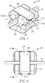
- FIGS. 7-11 show an orthodontic appliance 200 engaged to an archwire 50' and having many of the same features described with respect to appliance 100.
- the appliance 200 offers some added benefits as will be described below.
- the appliance 200 has a base 202 and a body 206 similarly configured to those shown for the appliance 100 in FIGS. 1-6 .
- Appliance 200 also has a door assembly 219 that includes a ligating cover 220 and resilient clip 222, the door assembly 219 jointly pivoting about a hinge 216 using hinge pin 217.
- the clip 222 differs significantly from the clip 122 in its overall size and shape, and manner of connecting to the ligating cover 220.
- the clip 222 has a generally "U"-shaped configuration, having two generally parallel shaft portions 226, each of the shaft portions 226 terminating in an eyelet 228 fastened to the hinge pin 217, as shown in FIG. 9 and 11 .
- On the opposite end of each shaft portion 226 is a hook portion 230 having characteristics similar to the earlier described clip 122.
- the clip 222 also has a generally straight connector portion 229 extending along a generally mesial-distal direction and interconnecting the terminal ends of the hook portions 230 as shown in FIG. 11 .
- the shaft portions 226 of the clip 222 are mechanically coupled to the ligating cover 220 by a set of flanges 270 that are located on the ligating cover 220 and extend along opposite-facing sides of the clip 222.
- the depicted embodiment in FIG. 11 shows four short flanges 270 on the lingual side of the clip 222 and two long flanges on the facial side of the clip 222.
- the ligating cover 220 and the clip 222 jointly rotate about the hinge pin 217 during operation of the appliance 200.
- other methods of coupling the ligating cover 220 and clip 222 are possible, including use of a set pin or adhesive.
- One of the advantages of using a non-planar clip, as embodied in the clip 222, is increased mesial-distal length along which the archwire 50' can contact the door assembly 219. Because the door assembly 219 can engage the archwire 50' at two locations that are spaced apart from each other along a mesial-distal direction, it is possible to reduce angular slop in the archwire 50' and achieve greater rotation control than otherwise achievable by engaging the archwire 50' at a single location.
- the clip 222 of the appliance 200 can provide for active ligation when the archwire 50' has a sufficiently large facial-lingual dimension.
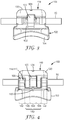
- FIG. 9 The cross-sectional view of FIG. 9 , taken along the section 9-9 in FIG. 8 , shows in greater detail the interaction between the appliance 200 and the archwire 50'.
- the terminal end of the hook portions 230, along with the connector portion 229, can precisely snap into an undercut 232 located on the gingival side of the body 206.
- the lingual underside of the clip 222 could include a shallow relief 280 (as shown) to tailor further the degree of space available for the archwire 50'. It is also possible, if desired, to adjust the spacing of the air gap 254 between the clip 222 and the facing surface of the ligating cover 220 to increase or decrease the degree of force that can be provided by the appliance 200 in an active ligation configuration. Similar benefits apply with respect to the appliance 100.
- FIG. 7 Another benefit, as shown in FIG. 7 , is the creation of a generally rectangular recess 290, located on the gingival side of the appliance 200, to assist in operating the appliance 200.
- the recess 290 is collectively defined by the hook portion 230, connector portion 229, and the ligating cover 220.
- the recess 290 is sufficiently sized to accommodate the tip of a hand instrument for operating the door assembly 219.
- the recess 290 is advantageously located at or near the mesial-distal midpoint of the gingival side of the appliance 200, allowing forces imparted by a hand instrument to be distributed evenly to the hook portions 230 and shaft portions 226.
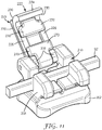
- FIG. 12 and 13 show an appliance 300 engaging an archwire 50", according to still another embodiment, in respective open and closed configurations.
- the appliance 300 has many of the same features as the appliance 200, including a base 302, body 306 with an archwire slot 310, and door assembly 319.
- the appliance 300 includes a door assembly 319 having a pair of planar, generally "J"-shaped clips 322a, 322b disposed on the mesial and distal sides of a ligating cover 320, respectively.
- each clip 322a, 322b has a hook portion 330a, 330b for releasably engaging an undercut 332 on the gingival side of the body 306.
- Certain potential benefits can be realized with a dual-clip configuration. For example, using a pair of planar clips 322a, 322b instead of a single integrated clip can help facilitate manufacturing. Further, the lack of a connector portion between the clips 322a, 322b provides for a slightly larger recess to accommodate a hand instrument for operating the door assembly 319. Finally, implementing a pair of clips instead of a singular clip can also decrease the effective force required to open the door assembly 319, since it is possible for clips 322a, 322b to disengage individually from corresponding undercut 332.
- appliances 200, 300 are analogous to those of the appliance 100 as previously described. Accordingly, corresponding options and features of the appliances 200, 300 will not be repeated.
- One of the unexpected advantages of the provided appliances 100, 200, 300 relates to the much lower labial force needed to open the door assembly 119, 219, 319 when applied at the terminal end of the clip 122, 222, 322, compared with the force needed when applied at the archwire slot 110, 210, 310. It was discovered that the clip 122, 222, 322, when deflected into a curved shape by the archwire, adopts a configuration that substantially increases the force required to disengage the clip 122, 222, 322 from the corresponding undercut 132, 232, 332.
- the actual force required to open the door assembly 119, 219, 319 is substantially greater at the archwire slot 110, 210, 310 than would be predicted geometrically by treating the door assembly 119, 219, 319 as a simple lever arm.
- the forces needed to unlatch the door assembly 119, 219, 319 can be quantified as follows. Unlatching the door assembly 119, 219, 319 by pivoting it from its closed to its open position requires a first minimum force applied to the clip 122, 222, 322 at the archwire slot 110, 210, 310 in a direction substantially perpendicular to the bottom wall of the archwire slot 110, 210, 310. Furthermore, the act of unlatching the door assembly 119, 219, 319 requires a second minimum force when applied to the clip 122, 222, 322 at its hook portion 130, 230, 330a, 330b (in the same direction). In some embodiments, the first minimum force exceeds the second minimum force by a factor of about 2.5, about 3, about 3.5, about 4, about 4.5, about 5, or about 6.
- the configuration of the clip 122, 222, 322 provides a novel answer to the technical challenge of allowing the practitioner to easily open the door assembly 119, 219, 319 using a low threshold force at the gingival end of the door assembly 119, 219, 319 (e.g. using the tip of a hand instrument at the recess 290), while avoiding spontaneous disengagement of the archwire by imposing a relatively high threshold force to open the door assembly 119, 219, 319 at the archwire slot 110, 210, 310.
- the comparative forces above can be simulated using, for example, finite element analysis ("FEA").
- FEA finite element analysis
- the threshold facial force required to open the door assembly 119 was simulated using ANSYS FEA software (ANSYS, Inc., Canonsburg, PA) to be about 4.9 newtons (1.1 lbf) at the set pin 138 of the clip 122, compared to about 28 newtons (6.2 lbf) at the archwire slot 110.
- This approximate 6:1 force ratio compares to a ratio of about 2:1 force ratio based on linear distance from the hinge axis 118.
Claims (11)
- Appareil orthodontique (100) comprenant :une base (102) ayant une surface externe (104) adaptée pour se lier à une dent ;un corps (106) s'étendant vers l'extérieur à partir de la base (102) dans une direction s'éloignant de la surface externe (104) de la base (102) et ayant une encoche d'arc dentaire allongée (110) s'étendant dans celui-ci le long d'une direction généralement mésio-distale, l'encoche d'arc dentaire (110) ayant une paroi de fond (112) et une paire de parois latérales (114), le corps (106) incluant en outre une contre-dépouille (132, 133) sur un côté soit occlusal soit gingival du corps (106) ;une articulation (116) couplée au corps (106) et ayant un axe d'articulation (118) s'étendant le long d'une direction généralement mésio-distale ; etun ensemble de porte (119) pouvant pivoter le long de l'axe d'articulation (118) entre une position ouverte permettant l'accès à l'encoche d'arc dentaire (110) et une position fermée obstruant l'accès à l'encoche d'arc dentaire (110), l'ensemble de porte (119) comprenant :un couvercle de ligature en céramique (120) ; etune attache élastique (122) couplée à la fois au couvercle de ligature (120) et à l'articulation (116), le couvercle de ligature (120) masquant sensiblement l'attache (122) lorsque l'ensemble de porte (119) est dans sa position fermée, l'attache (122) incluant une partie de crochet (130) retenue par un ajustement par interférence avec la contre-dépouille (132, 133) lorsque l'ensemble de porte (119) est dans sa position fermée, et l'attache (122) comprenant une partie d'arbre (126) et la partie de crochet (130) reliée au niveau d'une extrémité de la partie d'arbre (126), fournissant de ce fait une configuration généralement en forme de « J ».
- Appareil selon la revendication 1, comprenant en outre un espace d'air (154) s'étendant entre le couvercle de ligature (120) et l'attache (122), l'espace d'air (154) fournissant un espace pour l'attache (122) pour une déformation élastique dans une direction s'éloignant de la paroi de fond (112) de l'encoche d'arc dentaire (110) lors de la ligature active.
- Appareil selon la revendication 2, dans lequel l'espace d'air (154) a une épaisseur facio-linguale comprise dans la plage d'environ 25 micromètres à environ 510 micromètres.
- Appareil selon la revendication 1, dans lequel l'articulation (116) comprend une broche d'articulation (117) couplée de manière fonctionnelle à la fois à l'attache et au corps, dans lequel l'axe d'articulation est l'axe longitudinal de la broche d'articulation, et dans lequel la broche d'articulation (117) comprend une section centrale (140) et une paire de sections d'extrémité opposées (142), la section centrale (140) s'étendant à travers l'ensemble de porte (119) et les sections d'extrémité (142) s'étendant à travers le corps (106).
- Appareil selon la revendication 4, dans lequel la section centrale (140) comprend une sous-section centrale (144) et une paire de sous-sections d'extrémité (146), la sous-section centrale (144) s'étendant à travers l'attache (122) et les sous-sections d'extrémité (146) s'étendant à travers le couvercle de ligature (120).
- Appareil selon la revendication 4, dans lequel la section centrale (140) comprend une sous-section centrale (144) et une paire de sous-sections d'extrémité (146), la sous-section centrale (144) s'étendant à travers le couvercle de ligature (120) et les sous-sections d'extrémité (146) s'étendant à travers l'attache (122).
- Appareil selon la revendication 1, dans lequel l'attache (122) comprend en outre une languette (136) s'étendant vers l'extérieur à partir de la partie d'arbre (126) et comprenant en outre un goujon (138) s'étendant à travers à la fois le couvercle de ligature (120) et la languette (136) pour permettre au couvercle de ligature (120) et à l'attache (122) de tourner conjointement autour de l'axe d'articulation (118).
- Appareil selon la revendication 1, l'ensemble de porte (219) comprenant en outre un évidement (290) défini entre la partie de crochet (230) et le couvercle de ligature (220) lorsque l'ensemble de porte (219) est dans sa position fermée, dans lequel l'évidement (290) est suffisamment dimensionné pour recevoir la pointe d'un instrument à main pour le fonctionnement de l'ensemble de porte (219).
- Appareil selon la revendication 8, dans lequel le basculement de l'ensemble de porte (219) de sa position fermée à sa position ouverte nécessite une première force minimale lors de l'application à l'ensemble de porte (219) au niveau de l'encoche d'arc dentaire (110) et une deuxième force minimale lors de l'application à l'ensemble de porte (219) au niveau de l'évidement (290), la première force minimale dépassant la deuxième force minimale d'un facteur d'environ 2,5.
- Appareil selon la revendication 9, dans lequel la première force minimale dépasse la deuxième force minimale d'un facteur d'environ 6.
- Appareil selon l'une quelconque des revendications 1 à 10, comprenant en outre une pluralité de rebords (270) situés sur le couvercle de ligature (220) et s'étendant le long de côtés opposés en vis-à-vis de l'attache (222), moyennant quoi le couvercle de ligature (220) et l'attache (222) tournent conjointement autour de l'axe d'articulation (118).
Applications Claiming Priority (2)
| Application Number | Priority Date | Filing Date | Title |
|---|---|---|---|
| US201261674583P | 2012-07-23 | 2012-07-23 | |
| PCT/US2013/050545 WO2014018298A1 (fr) | 2012-07-23 | 2013-07-15 | Bracket orthodontique auto-ligaturant |
Publications (2)
| Publication Number | Publication Date |
|---|---|
| EP2874560A1 EP2874560A1 (fr) | 2015-05-27 |
| EP2874560B1 true EP2874560B1 (fr) | 2019-11-06 |
Family
ID=48857027
Family Applications (1)
| Application Number | Title | Priority Date | Filing Date |
|---|---|---|---|
| EP13740187.3A Active EP2874560B1 (fr) | 2012-07-23 | 2013-07-15 | Bracket orthodontique auto-ligaturant |
Country Status (6)
| Country | Link |
|---|---|
| US (1) | US9504539B2 (fr) |
| EP (1) | EP2874560B1 (fr) |
| JP (1) | JP6257620B2 (fr) |
| CN (1) | CN104812328B (fr) |
| BR (1) | BR112015001571A2 (fr) |
| WO (1) | WO2014018298A1 (fr) |
Families Citing this family (16)
| Publication number | Priority date | Publication date | Assignee | Title |
|---|---|---|---|---|
| US9504539B2 (en) | 2012-07-23 | 2016-11-29 | 3M Innovative Properties Company | Self-ligating orthodontic bracket |
| BR112017000439A2 (pt) * | 2014-07-09 | 2017-10-31 | 3M Innovative Properties Co | bráquete ortodôntico auto-ligante com trava de rotação positiva |
| KR101538007B1 (ko) * | 2015-04-15 | 2015-07-22 | 주식회사 바이오세텍 | 치열 교정용 브라켓 |
| US20180153650A1 (en) * | 2015-05-19 | 2018-06-07 | Erksine holdco Pty Ltd | Dental wire cap |
| US10085824B2 (en) | 2015-10-30 | 2018-10-02 | Ortho Organizers, Inc. | Self ligating orthodontic bracket |
| JP7051705B2 (ja) * | 2016-04-14 | 2022-04-11 | スリーエム イノベイティブ プロパティズ カンパニー | 歯の協調移動を促進する歯科矯正装置 |
| DE102017211867A1 (de) * | 2017-07-11 | 2019-01-17 | Dw Lingual Systems Gmbh | Anordnung mit einem Bracket und einem Clip |
| US11872101B2 (en) * | 2018-04-25 | 2024-01-16 | Lightforce Orthodontics, Inc. | Manufacture of patient-specific orthodontic brackets with improved base and retentive features |
| WO2019241251A1 (fr) | 2018-06-12 | 2019-12-19 | Lightforce Orthodontics, Inc. | Traitement et conception de céramique pour la fabrication directe d'accessoires d'aligneur transparent orthodontique lingual et labial personnalisés |
| US10264701B1 (en) * | 2018-06-28 | 2019-04-16 | Hewlett Packard Enterprise Development Lp | Multi-configuration resource module bay |
| US11583368B2 (en) | 2019-02-04 | 2023-02-21 | Yasuhiro Itsuki | Orthodontic bracket |
| KR102102262B1 (ko) * | 2019-11-11 | 2020-05-29 | 주식회사 바이오세텍 | 치아 교정용 브라켓 |
| CN111297498A (zh) * | 2020-03-21 | 2020-06-19 | 福建新安格口腔技术发展有限公司 | 正畸托槽和制造正畸托槽的方法 |
| US20210330429A1 (en) * | 2020-04-25 | 2021-10-28 | Premier Orthodontic Designs, Lllp | Passive Self-Ligation Bracket Assembly |
| KR102450201B1 (ko) * | 2020-06-30 | 2022-10-04 | 주식회사 메디센 | 치과 교정용 브라켓 |
| US11324573B2 (en) | 2020-07-03 | 2022-05-10 | Aadvance Technologies, Llc | Orthodontic device |
Family Cites Families (29)
| Publication number | Priority date | Publication date | Assignee | Title |
|---|---|---|---|---|
| US4536154A (en) | 1984-06-11 | 1985-08-20 | American Orthodontics Corporation | Edgewise bracket |
| US5078596A (en) | 1990-06-14 | 1992-01-07 | Minco, Inc. | Orthodontic bracket and associated fabricating method |
| US5254002B1 (en) | 1991-04-08 | 2000-01-11 | Ormco Corp | Orthodontic plastic bracket |
| US5439379A (en) | 1993-11-29 | 1995-08-08 | Minnesota Mining And Manufacturing Company | Ceramic orthodontic bracket with debonding channel |
| US6257883B1 (en) * | 1994-03-07 | 2001-07-10 | John C. Voudouris | Orthodontic bracket |
| US5474445A (en) * | 1994-03-07 | 1995-12-12 | John Voudouris | Self-engaging twin edge-wise orthodontic bracket with pivotal latch |
| US5685711A (en) * | 1995-12-06 | 1997-11-11 | Hanson; G. Herbert | Self-ligating orthodontic brackets |
| DE10035992A1 (de) * | 2000-07-24 | 2002-02-07 | Norbert Abels | Orthodontisches Bracket |
| WO2002064051A1 (fr) * | 2001-02-15 | 2002-08-22 | Norbert Abels | Verrous orthodontiques auto-ligaturants pourvus d'une base rigide et d'un fermoir deformable |
| CA2438236A1 (fr) * | 2001-02-15 | 2002-08-29 | Norbert Abels | Verrous orthodontiques a auto-ligature comportant un element de verrouillage securise de coiffe de ligature |
| US6932597B2 (en) | 2001-09-12 | 2005-08-23 | Norbert Abels | Self-ligating orthodontic brackets including a metal ligation cover hingedly connected to a bracket base |
| US6648638B2 (en) | 2001-12-28 | 2003-11-18 | 3M Innovative Properties Company | Orthodontic appliances including polycrystalline alumina-based ceramic material, kits, and methods |
| US7695277B1 (en) * | 2004-10-28 | 2010-04-13 | Rmo, Inc. | Orthodontic bracket with frangible cover mechanism |
| US20050019718A1 (en) | 2003-07-22 | 2005-01-27 | Hanson G. Herbert | Orthodontic devices for use with arch wires |
| US6964565B2 (en) * | 2004-02-19 | 2005-11-15 | Norbert Abels | Two-part orthodontic bracket |
| US7234935B2 (en) * | 2004-04-29 | 2007-06-26 | Norbert Abels | Orthodontic bracket system comprising multiple brackets having multiple aligned slots |
| US7247019B2 (en) * | 2004-04-30 | 2007-07-24 | Norbert Abels | Orthodontic brackets made from polymeric materials that impart desired strength properties |
| US7094052B2 (en) * | 2004-04-30 | 2006-08-22 | Norbert Abels | Orthodontic brackets with temporarily visible marking features |
| US20060199137A1 (en) * | 2005-03-04 | 2006-09-07 | Norbert Abels | Orthodontic retainer system with removable retaining wire |
| US7674110B2 (en) | 2006-03-23 | 2010-03-09 | Ormco Corporation | Low profile self-ligating orthodontic brackets and methods of using such orthodontic brackets |
| US7611352B2 (en) * | 2006-08-31 | 2009-11-03 | Ultradent Products, Inc. | Lifestyle bracket system having interchangeable ligation covers |
| US8376739B2 (en) * | 2011-05-12 | 2013-02-19 | Rmo, Inc. | Self ligating orthodontic bracket having a rotatable member |
| US20080241782A1 (en) | 2007-03-30 | 2008-10-02 | Norbert Abels | Two-part self-ligating orthodontic bracket having lateral guiding mechanism |
| DE102007062735B3 (de) * | 2007-12-27 | 2009-07-09 | Heiser, Wolfgang, Dr. med. habi. | Selbstligierendes kieferorthopädisches Bracket |
| JP2009164441A (ja) | 2008-01-09 | 2009-07-23 | Panasonic Corp | パターン形成方法 |
| US8235714B2 (en) * | 2009-08-12 | 2012-08-07 | World Class Technology Corporation | Convertible buccal tube orthodontic bracket |
| US9226803B2 (en) | 2010-01-25 | 2016-01-05 | Christopher C. Cosse | Orthodontic appliance systems |
| US9615897B2 (en) * | 2010-09-10 | 2017-04-11 | Ormco Corporation | Self-ligating orthodontic bracket |
| US9504539B2 (en) | 2012-07-23 | 2016-11-29 | 3M Innovative Properties Company | Self-ligating orthodontic bracket |
-
2013
- 2013-07-15 US US14/416,505 patent/US9504539B2/en active Active
- 2013-07-15 CN CN201380039379.0A patent/CN104812328B/zh not_active Expired - Fee Related
- 2013-07-15 BR BR112015001571A patent/BR112015001571A2/pt not_active Application Discontinuation
- 2013-07-15 JP JP2015524314A patent/JP6257620B2/ja not_active Expired - Fee Related
- 2013-07-15 WO PCT/US2013/050545 patent/WO2014018298A1/fr active Application Filing
- 2013-07-15 EP EP13740187.3A patent/EP2874560B1/fr active Active
Non-Patent Citations (1)
| Title |
|---|
| None * |
Also Published As
| Publication number | Publication date |
|---|---|
| US9504539B2 (en) | 2016-11-29 |
| CN104812328B (zh) | 2018-04-27 |
| WO2014018298A1 (fr) | 2014-01-30 |
| JP2015523166A (ja) | 2015-08-13 |
| JP6257620B2 (ja) | 2018-01-10 |
| US20150182307A1 (en) | 2015-07-02 |
| WO2014018298A9 (fr) | 2015-04-23 |
| BR112015001571A2 (pt) | 2017-07-04 |
| CN104812328A (zh) | 2015-07-29 |
| EP2874560A1 (fr) | 2015-05-27 |
Similar Documents
| Publication | Publication Date | Title |
|---|---|---|
| EP2874560B1 (fr) | Bracket orthodontique auto-ligaturant | |
| US20230200948A1 (en) | Self-ligating orthodontic bracket | |
| US9492246B2 (en) | Self-ligating orthodontic appliance and related methods | |
| US10123854B2 (en) | Self-ligating orthodontic bracket with positive rotation lock | |
| US9289274B2 (en) | Self-ligating orthodontic appliance | |
| US20150173859A1 (en) | Orthodontic appliance with ligating feature | |
| JP2020511266A (ja) | 結紮部材を備えた自己結紮ブラケット | |
| US11076936B2 (en) | Ceramic self-ligating bracket with high labial pull strength | |
| WO2017087533A1 (fr) | Bracket orthodontique auto-ligaturant | |
| US20230165663A1 (en) | Self-ligating orthodontic bracket |
Legal Events
| Date | Code | Title | Description |
|---|---|---|---|
| PUAI | Public reference made under article 153(3) epc to a published international application that has entered the european phase |
Free format text: ORIGINAL CODE: 0009012 |
|
| 17P | Request for examination filed |
Effective date: 20150129 |
|
| AK | Designated contracting states |
Kind code of ref document: A1 Designated state(s): AL AT BE BG CH CY CZ DE DK EE ES FI FR GB GR HR HU IE IS IT LI LT LU LV MC MK MT NL NO PL PT RO RS SE SI SK SM TR |
|
| AX | Request for extension of the european patent |
Extension state: BA ME |
|
| DAX | Request for extension of the european patent (deleted) | ||
| STAA | Information on the status of an ep patent application or granted ep patent |
Free format text: STATUS: EXAMINATION IS IN PROGRESS |
|
| 17Q | First examination report despatched |
Effective date: 20180319 |
|
| GRAP | Despatch of communication of intention to grant a patent |
Free format text: ORIGINAL CODE: EPIDOSNIGR1 |
|
| STAA | Information on the status of an ep patent application or granted ep patent |
Free format text: STATUS: GRANT OF PATENT IS INTENDED |
|
| INTG | Intention to grant announced |
Effective date: 20190517 |
|
| GRAS | Grant fee paid |
Free format text: ORIGINAL CODE: EPIDOSNIGR3 |
|
| GRAA | (expected) grant |
Free format text: ORIGINAL CODE: 0009210 |
|
| STAA | Information on the status of an ep patent application or granted ep patent |
Free format text: STATUS: THE PATENT HAS BEEN GRANTED |
|
| AK | Designated contracting states |
Kind code of ref document: B1 Designated state(s): AL AT BE BG CH CY CZ DE DK EE ES FI FR GB GR HR HU IE IS IT LI LT LU LV MC MK MT NL NO PL PT RO RS SE SI SK SM TR |
|
| REG | Reference to a national code |
Ref country code: GB Ref legal event code: FG4D |
|
| REG | Reference to a national code |
Ref country code: CH Ref legal event code: EP Ref country code: AT Ref legal event code: REF Ref document number: 1197740 Country of ref document: AT Kind code of ref document: T Effective date: 20191115 |
|
| REG | Reference to a national code |
Ref country code: IE Ref legal event code: FG4D |
|
| REG | Reference to a national code |
Ref country code: DE Ref legal event code: R096 Ref document number: 602013062535 Country of ref document: DE |
|
| REG | Reference to a national code |
Ref country code: NL Ref legal event code: MP Effective date: 20191106 |
|
| REG | Reference to a national code |
Ref country code: LT Ref legal event code: MG4D |
|
| PG25 | Lapsed in a contracting state [announced via postgrant information from national office to epo] |
Ref country code: SE Free format text: LAPSE BECAUSE OF FAILURE TO SUBMIT A TRANSLATION OF THE DESCRIPTION OR TO PAY THE FEE WITHIN THE PRESCRIBED TIME-LIMIT Effective date: 20191106 Ref country code: NL Free format text: LAPSE BECAUSE OF FAILURE TO SUBMIT A TRANSLATION OF THE DESCRIPTION OR TO PAY THE FEE WITHIN THE PRESCRIBED TIME-LIMIT Effective date: 20191106 Ref country code: PL Free format text: LAPSE BECAUSE OF FAILURE TO SUBMIT A TRANSLATION OF THE DESCRIPTION OR TO PAY THE FEE WITHIN THE PRESCRIBED TIME-LIMIT Effective date: 20191106 Ref country code: LV Free format text: LAPSE BECAUSE OF FAILURE TO SUBMIT A TRANSLATION OF THE DESCRIPTION OR TO PAY THE FEE WITHIN THE PRESCRIBED TIME-LIMIT Effective date: 20191106 Ref country code: NO Free format text: LAPSE BECAUSE OF FAILURE TO SUBMIT A TRANSLATION OF THE DESCRIPTION OR TO PAY THE FEE WITHIN THE PRESCRIBED TIME-LIMIT Effective date: 20200206 Ref country code: GR Free format text: LAPSE BECAUSE OF FAILURE TO SUBMIT A TRANSLATION OF THE DESCRIPTION OR TO PAY THE FEE WITHIN THE PRESCRIBED TIME-LIMIT Effective date: 20200207 Ref country code: LT Free format text: LAPSE BECAUSE OF FAILURE TO SUBMIT A TRANSLATION OF THE DESCRIPTION OR TO PAY THE FEE WITHIN THE PRESCRIBED TIME-LIMIT Effective date: 20191106 Ref country code: ES Free format text: LAPSE BECAUSE OF FAILURE TO SUBMIT A TRANSLATION OF THE DESCRIPTION OR TO PAY THE FEE WITHIN THE PRESCRIBED TIME-LIMIT Effective date: 20191106 Ref country code: PT Free format text: LAPSE BECAUSE OF FAILURE TO SUBMIT A TRANSLATION OF THE DESCRIPTION OR TO PAY THE FEE WITHIN THE PRESCRIBED TIME-LIMIT Effective date: 20200306 Ref country code: BG Free format text: LAPSE BECAUSE OF FAILURE TO SUBMIT A TRANSLATION OF THE DESCRIPTION OR TO PAY THE FEE WITHIN THE PRESCRIBED TIME-LIMIT Effective date: 20200206 Ref country code: FI Free format text: LAPSE BECAUSE OF FAILURE TO SUBMIT A TRANSLATION OF THE DESCRIPTION OR TO PAY THE FEE WITHIN THE PRESCRIBED TIME-LIMIT Effective date: 20191106 |
|
| PG25 | Lapsed in a contracting state [announced via postgrant information from national office to epo] |
Ref country code: RS Free format text: LAPSE BECAUSE OF FAILURE TO SUBMIT A TRANSLATION OF THE DESCRIPTION OR TO PAY THE FEE WITHIN THE PRESCRIBED TIME-LIMIT Effective date: 20191106 Ref country code: IS Free format text: LAPSE BECAUSE OF FAILURE TO SUBMIT A TRANSLATION OF THE DESCRIPTION OR TO PAY THE FEE WITHIN THE PRESCRIBED TIME-LIMIT Effective date: 20200306 Ref country code: HR Free format text: LAPSE BECAUSE OF FAILURE TO SUBMIT A TRANSLATION OF THE DESCRIPTION OR TO PAY THE FEE WITHIN THE PRESCRIBED TIME-LIMIT Effective date: 20191106 |
|
| PG25 | Lapsed in a contracting state [announced via postgrant information from national office to epo] |
Ref country code: AL Free format text: LAPSE BECAUSE OF FAILURE TO SUBMIT A TRANSLATION OF THE DESCRIPTION OR TO PAY THE FEE WITHIN THE PRESCRIBED TIME-LIMIT Effective date: 20191106 |
|
| PG25 | Lapsed in a contracting state [announced via postgrant information from national office to epo] |
Ref country code: EE Free format text: LAPSE BECAUSE OF FAILURE TO SUBMIT A TRANSLATION OF THE DESCRIPTION OR TO PAY THE FEE WITHIN THE PRESCRIBED TIME-LIMIT Effective date: 20191106 Ref country code: DK Free format text: LAPSE BECAUSE OF FAILURE TO SUBMIT A TRANSLATION OF THE DESCRIPTION OR TO PAY THE FEE WITHIN THE PRESCRIBED TIME-LIMIT Effective date: 20191106 Ref country code: CZ Free format text: LAPSE BECAUSE OF FAILURE TO SUBMIT A TRANSLATION OF THE DESCRIPTION OR TO PAY THE FEE WITHIN THE PRESCRIBED TIME-LIMIT Effective date: 20191106 Ref country code: RO Free format text: LAPSE BECAUSE OF FAILURE TO SUBMIT A TRANSLATION OF THE DESCRIPTION OR TO PAY THE FEE WITHIN THE PRESCRIBED TIME-LIMIT Effective date: 20191106 |
|
| REG | Reference to a national code |
Ref country code: DE Ref legal event code: R097 Ref document number: 602013062535 Country of ref document: DE |
|
| REG | Reference to a national code |
Ref country code: AT Ref legal event code: MK05 Ref document number: 1197740 Country of ref document: AT Kind code of ref document: T Effective date: 20191106 |
|
| PG25 | Lapsed in a contracting state [announced via postgrant information from national office to epo] |
Ref country code: SK Free format text: LAPSE BECAUSE OF FAILURE TO SUBMIT A TRANSLATION OF THE DESCRIPTION OR TO PAY THE FEE WITHIN THE PRESCRIBED TIME-LIMIT Effective date: 20191106 Ref country code: SM Free format text: LAPSE BECAUSE OF FAILURE TO SUBMIT A TRANSLATION OF THE DESCRIPTION OR TO PAY THE FEE WITHIN THE PRESCRIBED TIME-LIMIT Effective date: 20191106 |
|
| PLBE | No opposition filed within time limit |
Free format text: ORIGINAL CODE: 0009261 |
|
| STAA | Information on the status of an ep patent application or granted ep patent |
Free format text: STATUS: NO OPPOSITION FILED WITHIN TIME LIMIT |
|
| 26N | No opposition filed |
Effective date: 20200807 |
|
| PG25 | Lapsed in a contracting state [announced via postgrant information from national office to epo] |
Ref country code: SI Free format text: LAPSE BECAUSE OF FAILURE TO SUBMIT A TRANSLATION OF THE DESCRIPTION OR TO PAY THE FEE WITHIN THE PRESCRIBED TIME-LIMIT Effective date: 20191106 Ref country code: AT Free format text: LAPSE BECAUSE OF FAILURE TO SUBMIT A TRANSLATION OF THE DESCRIPTION OR TO PAY THE FEE WITHIN THE PRESCRIBED TIME-LIMIT Effective date: 20191106 |
|
| PG25 | Lapsed in a contracting state [announced via postgrant information from national office to epo] |
Ref country code: IT Free format text: LAPSE BECAUSE OF FAILURE TO SUBMIT A TRANSLATION OF THE DESCRIPTION OR TO PAY THE FEE WITHIN THE PRESCRIBED TIME-LIMIT Effective date: 20191106 |
|
| REG | Reference to a national code |
Ref country code: DE Ref legal event code: R119 Ref document number: 602013062535 Country of ref document: DE |
|
| PG25 | Lapsed in a contracting state [announced via postgrant information from national office to epo] |
Ref country code: MC Free format text: LAPSE BECAUSE OF FAILURE TO SUBMIT A TRANSLATION OF THE DESCRIPTION OR TO PAY THE FEE WITHIN THE PRESCRIBED TIME-LIMIT Effective date: 20191106 |
|
| REG | Reference to a national code |
Ref country code: CH Ref legal event code: PL |
|
| GBPC | Gb: european patent ceased through non-payment of renewal fee |
Effective date: 20200715 |
|
| REG | Reference to a national code |
Ref country code: BE Ref legal event code: MM Effective date: 20200731 |
|
| PG25 | Lapsed in a contracting state [announced via postgrant information from national office to epo] |
Ref country code: GB Free format text: LAPSE BECAUSE OF NON-PAYMENT OF DUE FEES Effective date: 20200715 Ref country code: LI Free format text: LAPSE BECAUSE OF NON-PAYMENT OF DUE FEES Effective date: 20200731 Ref country code: CH Free format text: LAPSE BECAUSE OF NON-PAYMENT OF DUE FEES Effective date: 20200731 Ref country code: LU Free format text: LAPSE BECAUSE OF NON-PAYMENT OF DUE FEES Effective date: 20200715 Ref country code: FR Free format text: LAPSE BECAUSE OF NON-PAYMENT OF DUE FEES Effective date: 20200731 |
|
| PG25 | Lapsed in a contracting state [announced via postgrant information from national office to epo] |
Ref country code: BE Free format text: LAPSE BECAUSE OF NON-PAYMENT OF DUE FEES Effective date: 20200731 Ref country code: DE Free format text: LAPSE BECAUSE OF NON-PAYMENT OF DUE FEES Effective date: 20210202 |
|
| PG25 | Lapsed in a contracting state [announced via postgrant information from national office to epo] |
Ref country code: IE Free format text: LAPSE BECAUSE OF NON-PAYMENT OF DUE FEES Effective date: 20200715 |
|
| PG25 | Lapsed in a contracting state [announced via postgrant information from national office to epo] |
Ref country code: TR Free format text: LAPSE BECAUSE OF FAILURE TO SUBMIT A TRANSLATION OF THE DESCRIPTION OR TO PAY THE FEE WITHIN THE PRESCRIBED TIME-LIMIT Effective date: 20191106 Ref country code: MT Free format text: LAPSE BECAUSE OF FAILURE TO SUBMIT A TRANSLATION OF THE DESCRIPTION OR TO PAY THE FEE WITHIN THE PRESCRIBED TIME-LIMIT Effective date: 20191106 Ref country code: CY Free format text: LAPSE BECAUSE OF FAILURE TO SUBMIT A TRANSLATION OF THE DESCRIPTION OR TO PAY THE FEE WITHIN THE PRESCRIBED TIME-LIMIT Effective date: 20191106 |
|
| PG25 | Lapsed in a contracting state [announced via postgrant information from national office to epo] |
Ref country code: MK Free format text: LAPSE BECAUSE OF FAILURE TO SUBMIT A TRANSLATION OF THE DESCRIPTION OR TO PAY THE FEE WITHIN THE PRESCRIBED TIME-LIMIT Effective date: 20191106 |