EP2873928B1 - Climatiseur - Google Patents
Climatiseur Download PDFInfo
- Publication number
- EP2873928B1 EP2873928B1 EP12886852.8A EP12886852A EP2873928B1 EP 2873928 B1 EP2873928 B1 EP 2873928B1 EP 12886852 A EP12886852 A EP 12886852A EP 2873928 B1 EP2873928 B1 EP 2873928B1
- Authority
- EP
- European Patent Office
- Prior art keywords
- temperature
- target
- mode
- refrigerant
- evaporation temperature
- Prior art date
- Legal status (The legal status is an assumption and is not a legal conclusion. Google has not performed a legal analysis and makes no representation as to the accuracy of the status listed.)
- Active
Links
- 239000003507 refrigerant Substances 0.000 claims description 303
- 238000001704 evaporation Methods 0.000 claims description 292
- 230000008020 evaporation Effects 0.000 claims description 292
- 230000005494 condensation Effects 0.000 claims description 272
- 238000009833 condensation Methods 0.000 claims description 272
- 238000004378 air conditioning Methods 0.000 claims description 121
- 230000001143 conditioned effect Effects 0.000 claims description 18
- 238000001816 cooling Methods 0.000 description 44
- 238000010438 heat treatment Methods 0.000 description 44
- 238000004134 energy conservation Methods 0.000 description 33
- 239000007788 liquid Substances 0.000 description 25
- 230000007246 mechanism Effects 0.000 description 16
- 230000008859 change Effects 0.000 description 14
- 230000006870 function Effects 0.000 description 14
- 101000661807 Homo sapiens Suppressor of tumorigenicity 14 protein Proteins 0.000 description 8
- 230000002123 temporal effect Effects 0.000 description 8
- 230000004048 modification Effects 0.000 description 7
- 238000012986 modification Methods 0.000 description 7
- 101000911772 Homo sapiens Hsc70-interacting protein Proteins 0.000 description 5
- 101001139126 Homo sapiens Krueppel-like factor 6 Proteins 0.000 description 4
- 230000006835 compression Effects 0.000 description 4
- 238000007906 compression Methods 0.000 description 4
- 238000010586 diagram Methods 0.000 description 4
- 101000710013 Homo sapiens Reversion-inducing cysteine-rich protein with Kazal motifs Proteins 0.000 description 3
- 230000001010 compromised effect Effects 0.000 description 2
- 238000001514 detection method Methods 0.000 description 2
- 230000005855 radiation Effects 0.000 description 2
- 101000859448 Homo sapiens Beta/gamma crystallin domain-containing protein 1 Proteins 0.000 description 1
- 108050005271 Stromelysin-3 Proteins 0.000 description 1
- 238000004891 communication Methods 0.000 description 1
- 238000009434 installation Methods 0.000 description 1
- 238000005057 refrigeration Methods 0.000 description 1
Images


Classifications
-
- F—MECHANICAL ENGINEERING; LIGHTING; HEATING; WEAPONS; BLASTING
- F24—HEATING; RANGES; VENTILATING
- F24F—AIR-CONDITIONING; AIR-HUMIDIFICATION; VENTILATION; USE OF AIR CURRENTS FOR SCREENING
- F24F5/00—Air-conditioning systems or apparatus not covered by F24F1/00 or F24F3/00, e.g. using solar heat or combined with household units such as an oven or water heater
- F24F5/0007—Air-conditioning systems or apparatus not covered by F24F1/00 or F24F3/00, e.g. using solar heat or combined with household units such as an oven or water heater cooling apparatus specially adapted for use in air-conditioning
- F24F5/0035—Air-conditioning systems or apparatus not covered by F24F1/00 or F24F3/00, e.g. using solar heat or combined with household units such as an oven or water heater cooling apparatus specially adapted for use in air-conditioning using evaporation
-
- F—MECHANICAL ENGINEERING; LIGHTING; HEATING; WEAPONS; BLASTING
- F24—HEATING; RANGES; VENTILATING
- F24F—AIR-CONDITIONING; AIR-HUMIDIFICATION; VENTILATION; USE OF AIR CURRENTS FOR SCREENING
- F24F11/00—Control or safety arrangements
- F24F11/30—Control or safety arrangements for purposes related to the operation of the system, e.g. for safety or monitoring
-
- F—MECHANICAL ENGINEERING; LIGHTING; HEATING; WEAPONS; BLASTING
- F24—HEATING; RANGES; VENTILATING
- F24F—AIR-CONDITIONING; AIR-HUMIDIFICATION; VENTILATION; USE OF AIR CURRENTS FOR SCREENING
- F24F11/00—Control or safety arrangements
- F24F11/62—Control or safety arrangements characterised by the type of control or by internal processing, e.g. using fuzzy logic, adaptive control or estimation of values
-
- F—MECHANICAL ENGINEERING; LIGHTING; HEATING; WEAPONS; BLASTING
- F24—HEATING; RANGES; VENTILATING
- F24F—AIR-CONDITIONING; AIR-HUMIDIFICATION; VENTILATION; USE OF AIR CURRENTS FOR SCREENING
- F24F11/00—Control or safety arrangements
- F24F11/89—Arrangement or mounting of control or safety devices
-
- F—MECHANICAL ENGINEERING; LIGHTING; HEATING; WEAPONS; BLASTING
- F25—REFRIGERATION OR COOLING; COMBINED HEATING AND REFRIGERATION SYSTEMS; HEAT PUMP SYSTEMS; MANUFACTURE OR STORAGE OF ICE; LIQUEFACTION SOLIDIFICATION OF GASES
- F25B—REFRIGERATION MACHINES, PLANTS OR SYSTEMS; COMBINED HEATING AND REFRIGERATION SYSTEMS; HEAT PUMP SYSTEMS
- F25B13/00—Compression machines, plants or systems, with reversible cycle
-
- F—MECHANICAL ENGINEERING; LIGHTING; HEATING; WEAPONS; BLASTING
- F24—HEATING; RANGES; VENTILATING
- F24F—AIR-CONDITIONING; AIR-HUMIDIFICATION; VENTILATION; USE OF AIR CURRENTS FOR SCREENING
- F24F2140/00—Control inputs relating to system states
- F24F2140/20—Heat-exchange fluid temperature
-
- F—MECHANICAL ENGINEERING; LIGHTING; HEATING; WEAPONS; BLASTING
- F25—REFRIGERATION OR COOLING; COMBINED HEATING AND REFRIGERATION SYSTEMS; HEAT PUMP SYSTEMS; MANUFACTURE OR STORAGE OF ICE; LIQUEFACTION SOLIDIFICATION OF GASES
- F25B—REFRIGERATION MACHINES, PLANTS OR SYSTEMS; COMBINED HEATING AND REFRIGERATION SYSTEMS; HEAT PUMP SYSTEMS
- F25B2313/00—Compression machines, plants or systems with reversible cycle not otherwise provided for
- F25B2313/023—Compression machines, plants or systems with reversible cycle not otherwise provided for using multiple indoor units
- F25B2313/0233—Compression machines, plants or systems with reversible cycle not otherwise provided for using multiple indoor units in parallel arrangements
-
- F—MECHANICAL ENGINEERING; LIGHTING; HEATING; WEAPONS; BLASTING
- F25—REFRIGERATION OR COOLING; COMBINED HEATING AND REFRIGERATION SYSTEMS; HEAT PUMP SYSTEMS; MANUFACTURE OR STORAGE OF ICE; LIQUEFACTION SOLIDIFICATION OF GASES
- F25B—REFRIGERATION MACHINES, PLANTS OR SYSTEMS; COMBINED HEATING AND REFRIGERATION SYSTEMS; HEAT PUMP SYSTEMS
- F25B2313/00—Compression machines, plants or systems with reversible cycle not otherwise provided for
- F25B2313/027—Compression machines, plants or systems with reversible cycle not otherwise provided for characterised by the reversing means
- F25B2313/02741—Compression machines, plants or systems with reversible cycle not otherwise provided for characterised by the reversing means using one four-way valve
-
- F—MECHANICAL ENGINEERING; LIGHTING; HEATING; WEAPONS; BLASTING
- F25—REFRIGERATION OR COOLING; COMBINED HEATING AND REFRIGERATION SYSTEMS; HEAT PUMP SYSTEMS; MANUFACTURE OR STORAGE OF ICE; LIQUEFACTION SOLIDIFICATION OF GASES
- F25B—REFRIGERATION MACHINES, PLANTS OR SYSTEMS; COMBINED HEATING AND REFRIGERATION SYSTEMS; HEAT PUMP SYSTEMS
- F25B2313/00—Compression machines, plants or systems with reversible cycle not otherwise provided for
- F25B2313/029—Control issues
-
- F—MECHANICAL ENGINEERING; LIGHTING; HEATING; WEAPONS; BLASTING
- F25—REFRIGERATION OR COOLING; COMBINED HEATING AND REFRIGERATION SYSTEMS; HEAT PUMP SYSTEMS; MANUFACTURE OR STORAGE OF ICE; LIQUEFACTION SOLIDIFICATION OF GASES
- F25B—REFRIGERATION MACHINES, PLANTS OR SYSTEMS; COMBINED HEATING AND REFRIGERATION SYSTEMS; HEAT PUMP SYSTEMS
- F25B2313/00—Compression machines, plants or systems with reversible cycle not otherwise provided for
- F25B2313/031—Sensor arrangements
- F25B2313/0313—Pressure sensors near the outdoor heat exchanger
-
- F—MECHANICAL ENGINEERING; LIGHTING; HEATING; WEAPONS; BLASTING
- F25—REFRIGERATION OR COOLING; COMBINED HEATING AND REFRIGERATION SYSTEMS; HEAT PUMP SYSTEMS; MANUFACTURE OR STORAGE OF ICE; LIQUEFACTION SOLIDIFICATION OF GASES
- F25B—REFRIGERATION MACHINES, PLANTS OR SYSTEMS; COMBINED HEATING AND REFRIGERATION SYSTEMS; HEAT PUMP SYSTEMS
- F25B2313/00—Compression machines, plants or systems with reversible cycle not otherwise provided for
- F25B2313/031—Sensor arrangements
- F25B2313/0314—Temperature sensors near the indoor heat exchanger
-
- F—MECHANICAL ENGINEERING; LIGHTING; HEATING; WEAPONS; BLASTING
- F25—REFRIGERATION OR COOLING; COMBINED HEATING AND REFRIGERATION SYSTEMS; HEAT PUMP SYSTEMS; MANUFACTURE OR STORAGE OF ICE; LIQUEFACTION SOLIDIFICATION OF GASES
- F25B—REFRIGERATION MACHINES, PLANTS OR SYSTEMS; COMBINED HEATING AND REFRIGERATION SYSTEMS; HEAT PUMP SYSTEMS
- F25B2600/00—Control issues
- F25B2600/19—Refrigerant outlet condenser temperature
-
- F—MECHANICAL ENGINEERING; LIGHTING; HEATING; WEAPONS; BLASTING
- F25—REFRIGERATION OR COOLING; COMBINED HEATING AND REFRIGERATION SYSTEMS; HEAT PUMP SYSTEMS; MANUFACTURE OR STORAGE OF ICE; LIQUEFACTION SOLIDIFICATION OF GASES
- F25B—REFRIGERATION MACHINES, PLANTS OR SYSTEMS; COMBINED HEATING AND REFRIGERATION SYSTEMS; HEAT PUMP SYSTEMS
- F25B2600/00—Control issues
- F25B2600/21—Refrigerant outlet evaporator temperature
-
- F—MECHANICAL ENGINEERING; LIGHTING; HEATING; WEAPONS; BLASTING
- F25—REFRIGERATION OR COOLING; COMBINED HEATING AND REFRIGERATION SYSTEMS; HEAT PUMP SYSTEMS; MANUFACTURE OR STORAGE OF ICE; LIQUEFACTION SOLIDIFICATION OF GASES
- F25B—REFRIGERATION MACHINES, PLANTS OR SYSTEMS; COMBINED HEATING AND REFRIGERATION SYSTEMS; HEAT PUMP SYSTEMS
- F25B2700/00—Sensing or detecting of parameters; Sensors therefor
- F25B2700/19—Pressures
- F25B2700/193—Pressures of the compressor
- F25B2700/1931—Discharge pressures
-
- F—MECHANICAL ENGINEERING; LIGHTING; HEATING; WEAPONS; BLASTING
- F25—REFRIGERATION OR COOLING; COMBINED HEATING AND REFRIGERATION SYSTEMS; HEAT PUMP SYSTEMS; MANUFACTURE OR STORAGE OF ICE; LIQUEFACTION SOLIDIFICATION OF GASES
- F25B—REFRIGERATION MACHINES, PLANTS OR SYSTEMS; COMBINED HEATING AND REFRIGERATION SYSTEMS; HEAT PUMP SYSTEMS
- F25B2700/00—Sensing or detecting of parameters; Sensors therefor
- F25B2700/19—Pressures
- F25B2700/193—Pressures of the compressor
- F25B2700/1933—Suction pressures
-
- F—MECHANICAL ENGINEERING; LIGHTING; HEATING; WEAPONS; BLASTING
- F25—REFRIGERATION OR COOLING; COMBINED HEATING AND REFRIGERATION SYSTEMS; HEAT PUMP SYSTEMS; MANUFACTURE OR STORAGE OF ICE; LIQUEFACTION SOLIDIFICATION OF GASES
- F25B—REFRIGERATION MACHINES, PLANTS OR SYSTEMS; COMBINED HEATING AND REFRIGERATION SYSTEMS; HEAT PUMP SYSTEMS
- F25B2700/00—Sensing or detecting of parameters; Sensors therefor
- F25B2700/21—Temperatures
- F25B2700/2106—Temperatures of fresh outdoor air
-
- F—MECHANICAL ENGINEERING; LIGHTING; HEATING; WEAPONS; BLASTING
- F25—REFRIGERATION OR COOLING; COMBINED HEATING AND REFRIGERATION SYSTEMS; HEAT PUMP SYSTEMS; MANUFACTURE OR STORAGE OF ICE; LIQUEFACTION SOLIDIFICATION OF GASES
- F25B—REFRIGERATION MACHINES, PLANTS OR SYSTEMS; COMBINED HEATING AND REFRIGERATION SYSTEMS; HEAT PUMP SYSTEMS
- F25B2700/00—Sensing or detecting of parameters; Sensors therefor
- F25B2700/21—Temperatures
- F25B2700/2115—Temperatures of a compressor or the drive means therefor
- F25B2700/21151—Temperatures of a compressor or the drive means therefor at the suction side of the compressor
-
- F—MECHANICAL ENGINEERING; LIGHTING; HEATING; WEAPONS; BLASTING
- F25—REFRIGERATION OR COOLING; COMBINED HEATING AND REFRIGERATION SYSTEMS; HEAT PUMP SYSTEMS; MANUFACTURE OR STORAGE OF ICE; LIQUEFACTION SOLIDIFICATION OF GASES
- F25B—REFRIGERATION MACHINES, PLANTS OR SYSTEMS; COMBINED HEATING AND REFRIGERATION SYSTEMS; HEAT PUMP SYSTEMS
- F25B2700/00—Sensing or detecting of parameters; Sensors therefor
- F25B2700/21—Temperatures
- F25B2700/2115—Temperatures of a compressor or the drive means therefor
- F25B2700/21152—Temperatures of a compressor or the drive means therefor at the discharge side of the compressor
Definitions
- the present invention relates to an air conditioning apparatus and particularly an air conditioning apparatus equipped with a refrigerant circuit configured as a result of plural indoor units being connected to an outdoor unit.
- an air conditioning apparatus equipped with a refrigerant circuit configured as a result of plural indoor units being connected to an outdoor unit.
- this air conditioning apparatus there is an air conditioning apparatus that has a capacity controlling part that controls the air conditioning capacity of the outdoor unit (specifically, the operating capacity of the compressor) in such a way that the evaporation temperature or the condensation temperature of refrigerant in the refrigerant circuit becomes a target evaporation temperature or a target condensation temperature.
- a capacity controlling part controls the air conditioning capacity of the outdoor unit (specifically, the operating capacity of the compressor) in such a way that the evaporation temperature or the condensation temperature of refrigerant in the refrigerant circuit becomes a target evaporation temperature or a target condensation temperature.
- patent document 1 JP-A No. 2002-147823
- US 6,701,732 B2 discloses an air conditioning apparatus equipped with a refrigerant circuit configured as a result of plural indoor units being connected to an outdoor unit, the air conditioning apparatus comprising: a capacity controlling part that controls an air conditioning capacity of the outdoor unit in such a way that an evaporation temperature or a condensation temperature of refrigerant in the refrigerant circuit becomes a target evaporation temperature or a target condensation temperature.
- US 6,701,732 B2 discloses an air conditioning apparatus according to the preamble of claim 1.
- the air conditioning apparatus By changing the target evaporation temperature or the target condensation temperature as described above, an excess of the air conditioning capacity of the outdoor unit can be suppressed, the frequency with which the indoor units and the compressor alternate between being operated and being stopped can be reduced, and energy conservation can be improved. For this reason, the air conditioning apparatus easily satisfies users who prefer to conserve energy.
- the air conditioning apparatus does not easily satisfy users who prefer comfort.
- An air conditioning apparatus pertaining to a first aspect is an air conditioning apparatus equipped with a refrigerant circuit configured as a result of plural indoor units being connected to an outdoor unit, the air conditioning apparatus having a capacity controlling part and a target refrigerant temperature mode setting part.
- the capacity controlling part is a part that controls the air conditioning capacity of the outdoor unit in such a way that the evaporation temperature or the condensation temperature of refrigerant in the refrigerant circuit becomes a target evaporation temperature or a target condensation temperature.
- the target refrigerant temperature mode setting part is a part configured to set a target refrigerant temperature mode to either of a target refrigerant temperature changing mode that changes the target evaporation temperature or the target condensation temperature and a target refrigerant temperature fixing mode that fixes the target evaporation temperature or the target condensation temperature.
- evaporation temperature means a state quantity that is equivalent to the evaporation pressure in the refrigerant circuit
- condensation temperature means a state quantity that is equivalent to the condensation pressure in the refrigerant circuit. That is, “evaporation pressure” and “evaporation temperature”, “target evaporation pressure” and “target evaporation temperature”, “condensation pressure” and “condensation temperature”, and “target condensation pressure” and “target condensation temperature” mean substantially the same state quantities even though the wordings themselves are different.
- the target refrigerant temperature mode can be set to either of the target refrigerant temperature changing mode and the target refrigerant temperature fixing mode by the target refrigerant temperature mode setting part. Additionally, when the target refrigerant temperature mode is set to the target refrigerant temperature changing mode, priority can be given to energy conservation, and when the target refrigerant temperature mode is set to the target refrigerant temperature fixing mode, priority can be given to comfort.
- priority can be given to energy conservation or priority can be given to comfort according to the preference of the user.
- An air conditioning apparatus pertaining to a second aspect is the air conditioning apparatus pertaining to the first aspect, wherein the target refrigerant temperature changing mode has a fast changing mode and a slow changing mode.
- the fast changing mode is a mode that changes the target evaporation temperature or the target condensation temperature in such a way that room temperatures of air conditioned spaces targeted by the indoor units reach, in a short amount of time, set temperatures that are target values of the room temperatures.
- the slow changing mode is a mode that changes the target evaporation temperature or the target condensation temperature in such a way that the room temperatures reach the set temperatures in a longer amount of time than in the fast changing mode. Additionally, the fast changing mode and the slow changing mode are set by the target refrigerant temperature mode setting part.
- the target refrigerant temperature mode when the target refrigerant temperature mode is set to the target refrigerant temperature changing mode by the target refrigerant temperature mode setting part, the target refrigerant temperature mode can be set to either of two modes-the fast changing mode and the slow changing mode-in which the degree of control trackability is different. Additionally, when the target refrigerant temperature mode is set to the fast changing mode, control trackability is improved compared to a case where the target refrigerant temperature mode is set to the slow changing mode.
- An air conditioning apparatus pertaining to a third aspect is the air conditioning apparatus pertaining to the second aspect, wherein in the target refrigerant temperature fixing mode, the target evaporation temperature or the target condensation temperature is fixed to a maximum capacity evaporation temperature or a maximum capacity condensation temperature corresponding to a case where the air conditioning capacity of the outdoor unit is at 100% capacity.
- the target evaporation temperature or the target condensation temperature is constantly fixed to the maximum capacity evaporation temperature or the maximum capacity condensation temperature.
- air conditioning operations can be performed in a state in which priority is constantly given to comfort.
- An air conditioning apparatus pertaining to a fourth aspect is the air conditioning apparatus pertaining to the third aspect, wherein the fast changing mode has a powerful mode and a quick mode.
- the powerful mode is a mode that allows the target evaporation temperature or the target condensation temperature to be changed to a lowest evaporation temperature or a highest condensation temperature exceeding the maximum capacity evaporation temperature or the maximum capacity condensation temperature.
- the quick mode is a mode that does not allow the target evaporation temperature or the target condensation temperature to be changed to the lowest evaporation temperature or the highest condensation temperature. Additionally, the powerful mode and the quick mode are set by the target refrigerant temperature mode setting part.
- the target refrigerant temperature mode when the target refrigerant temperature mode is set to the fast changing mode of the target refrigerant temperature changing mode by the target refrigerant temperature mode setting part, the target refrigerant temperature mode can be set to either of two modes-the powerful mode and the quick mode-in which the degree of control trackability is further different. Additionally, when the target refrigerant temperature mode is set to the powerful mode, the target evaporation temperature or the target condensation temperature is allowed to be changed to the lowest evaporation temperature or the highest condensation temperature exceeding the maximum capacity evaporation temperature or the maximum capacity condensation temperature, so control trackability is further improved compared to a case where the target refrigerant temperature mode is set to the quick mode.
- control trackability can be improved, and at the same time the degree of control trackability can be further changed according to the preference of the user.
- An air conditioning apparatus pertaining to a fifth aspect is the air conditioning apparatus pertaining to any of the second to fourth aspects, wherein the target refrigerant temperature changing mode further has an automatic mode and a high-sensitivity mode.
- the automatic mode is a mode that sets a reference target evaporation temperature or a reference target condensation temperature serving as a reference value of the target evaporation temperature or the target condensation temperature in accordance with an outdoor temperature of an outside space where the outdoor unit is disposed.
- the high-sensitivity mode is a mode in which a user sets the reference target evaporation temperature or the reference target condensation temperature. Additionally, the fast changing mode and the slow changing mode are set, together with the automatic mode or the high-sensitivity mode, by the target refrigerant temperature mode setting part. The target evaporation temperature or the target condensation temperature is changed by making, with respect to the reference target evaporation temperature or the reference target condensation temperature, a correction corresponding to the fast changing mode or the slow changing mode.
- the target refrigerant temperature mode when the target refrigerant temperature mode is set to the target refrigerant temperature changing mode by the target refrigerant temperature mode setting part, the target refrigerant temperature mode can be set to either of two modes-the automatic mode and the high-sensitivity mode-in which the way of setting the reference target evaporation temperature or the reference target condensation temperature is different.
- the reference target evaporation temperature or the reference target condensation temperature is set in accordance with the outdoor temperature, so the target evaporation temperature or the target condensation temperature that is set as a result of a correction corresponding to the fast changing mode and the slow changing mode being made to the reference target evaporation temperature or the reference target condensation temperature can further improve the degree of energy conservation compared to a case where the target refrigerant temperature mode is set to the high-sensitivity mode.
- the target refrigerant temperature mode is set to the high-sensitivity mode, the degree of energy conservation can be set according to the preference of the user.
- An air conditioning apparatus pertaining to a sixth aspect is the air conditioning apparatus pertaining to the fifth aspect, wherein the target refrigerant temperature changing mode further has an economy mode.
- the economy mode is a mode in which the reference target evaporation temperature or the reference target condensation temperature that has been set in the automatic mode or the high-sensitivity mode is set as the target evaporation temperature or the target condensation temperature without a correction being made to that reference target evaporation temperature or that reference target condensation temperature. Additionally, the economy mode is set, together with the automatic mode or the high-sensitivity mode, by the target refrigerant temperature mode setting part.
- the target refrigerant temperature mode when the target refrigerant temperature mode is set to the automatic mode or the high-sensitivity mode of the target refrigerant temperature changing mode by the target refrigerant temperature mode setting part, the target refrigerant temperature mode can be set to any of three modes including, in addition to the fast changing mode and the slow changing mode, the economy mode in which the way of correcting the reference target evaporation temperature or the reference target condensation temperature that has been set in the automatic mode or the high-sensitivity mode is different. Additionally, when the target refrigerant temperature mode is set to the economy mode, the target evaporation temperature or the target condensation temperature is set without a correction being made to the reference target evaporation temperature or the reference target condensation temperature, so the degree of control trackability can be brought closest to the preference of the user.
- the degree of energy conservation can be set, and at the same time the degree of control trackability can be changed according to the preference of the user.
- An air conditioning apparatus pertaining to a seventh aspect is the air conditioning apparatus pertaining to the fifth or sixth aspect, wherein the reference target evaporation temperature is restricted to be equal to or less than an upper limit evaporation temperature that has been set in accordance with the room temperatures.
- the reference target evaporation temperature is set in accordance with the outdoor temperature in the automatic mode and is set by the user in the high-sensitivity mode, so in an operating state in which the outdoor temperature is high and the room temperatures are low, there can be cases where the humidity in the air conditioned spaces becomes higher than the relative humidity (usually about 60%) suitable for the room temperatures. When the relative humidity becomes higher, discomfort increases in the air conditioned spaces, so this kind of operating state needs to be avoided.
- the reference target evaporation temperature that is set in the automatic mode and the high-sensitivity mode is restricted to be equal to or less than the upper limit evaporation temperature that has been set in accordance with the room temperatures, so it is ensured that the humidity in the air conditioned spaces becomes equal to or less than the relative humidity suitable for the room temperatures.
- FIG. 1 is a schematic configuration diagram of an air conditioning apparatus 1 pertaining to an embodiment of the present invention.
- the air conditioning apparatus 1 is a apparatus used to air condition the inside of a building or the like by performing a vapor compression refrigeration cycle operation.
- the air conditioning apparatus 1 is mainly configured as a result of an outdoor unit 2 and plural (here, two) indoor units 4a and 4b being connected to one another.
- the outdoor unit 2 and the plural indoor units 4a and 4b are connected to one another via a liquid refrigerant connection pipe 6 and a gas refrigerant connection pipe 7. That is, a vapor compression refrigerant circuit 10 of the air conditioning apparatus 1 is configured as a result of the outdoor unit 2 and the plural indoor units 4a and 4b being connected to one another via the refrigerant connection pipes 6 and 7.
- the indoor units 4a and 4b are installed indoors.
- the indoor units 4a and 4b are connected to the outdoor unit 2 via the refrigerant connection pipes 6 and 7 and configure part of the refrigerant circuit 10.
- the indoor unit 4b has the same configuration as the indoor unit 4a, so here just the configuration of the indoor unit 4a will be described; regarding the configuration of the indoor unit 4b, the letter "b" will be added instead of the letter "a” indicating each part of the indoor unit 4a, and description of each part of the indoor unit 4b will be omitted.
- the indoor unit 4a mainly has an indoor-side refrigerant circuit 10a (an indoor-side refrigerant circuit 10b in the indoor unit 4b) that configures part of the refrigerant circuit 10.
- the indoor-side refrigerant circuit 10a mainly has an indoor expansion valve 41a and an indoor heat exchanger 42a.
- the indoor expansion valve 41a is a valve that reduces the pressure of refrigerant flowing through the indoor-side refrigerant circuit 10a to thereby adjust the flow rate of the refrigerant.
- the indoor expansion valve 41a is an electrically powered expansion valve connected to the liquid side of the indoor heat exchanger 42a.
- the indoor heat exchanger 42a comprises a cross-fin type fin and tube heat exchanger, for example.
- an indoor fan 43a for delivering room air to the indoor heat exchanger 42a. Heat exchange takes place between the refrigerant and the room air in the indoor heat exchanger 42a as a result of the indoor fan 43a delivering the room air to the indoor heat exchanger 42a.
- the indoor fan 43a is driven to rotate by an indoor fan motor 44a. Because of this, the indoor heat exchanger 42a functions as a radiator of the refrigerant and an evaporator of the refrigerant.
- various sensors are disposed in the indoor unit 4a.
- a liquid-side temperature sensor 45a that detects a temperature Trla of the refrigerant in a liquid state or a gas-liquid two-phase state.
- a gas-side temperature sensor 46a that detects a temperature Trga of the refrigerant in a gas state.
- a room temperature sensor 47a that detects the temperature of the room air (i.e., a room temperature Tra) in the air conditioned space targeted by the indoor unit 4a.
- the indoor unit 4a has an indoor-side control unit 48a that controls the actions of each part configuring the indoor unit 4a.
- the indoor-side control unit 48a has a microcomputer, which is disposed in order to control the indoor unit 4a, and a memory and the like, and the indoor-side control unit 48a can exchange control signals and so forth with a remote controller 49a for individually operating the indoor unit 4a and can exchange control signals and so forth with the outdoor unit 2.
- the remote controller 49a is a device for a user to make various settings relating to air conditioning operations and issue operate/stop commands.
- the outdoor unit 2 is installed outdoors.
- the outdoor unit 2 is connected to the indoor units 4a and 4b via the refrigerant connection pipes 6 and 7 and configures part of the refrigerant circuit 10.
- the outdoor unit 2 mainly has an outdoor-side refrigerant circuit 10c that configures part of the refrigerant circuit 10.
- the outdoor-side refrigerant circuit 10c mainly has a compressor 21, a switching mechanism 22, an outdoor heat exchanger 23, and an outdoor expansion valve 24.
- the compressor 21 is a closed compressor having a casing inside of which are housed a non-illustrated compression element and a compressor motor 20 that drives the compression element to rotate.
- the compressor motor 20 is supplied with electrical power via a non-illustrated inverter device, and its operating capacity can be changed by changing the frequency (i.e., the rotational speed) of the inverter device.
- the switching mechanism 22 is a four-way switching valve for switching the direction of the flow of the refrigerant.
- the switching mechanism 22 can interconnect the discharge side of the compressor 21 and the gas side of the outdoor heat exchanger 23 and also interconnect the suction side of the compressor 21 and the gas refrigerant connection pipe 7 in order to cause the outdoor heat exchanger 23 to function as a radiator of the refrigerant that has been compressed in the compressor 21 and cause the indoor heat exchangers 42a and 42b to function as evaporators of the refrigerant that has radiated heat in the outdoor heat exchanger 23 (a radiation switching state; see the solid lines of the switching mechanism 22 in FIG.
- the switching mechanism 22 can interconnect the discharge side of the compressor 21 and the gas refrigerant connection pipe 7 and also interconnect the suction side of the compressor 21 and the gas side of the outdoor heat exchanger 23 in order to cause the indoor heat exchangers 42a and 42b to function as radiators of the refrigerant that has been compressed in the compressor 21 and cause the outdoor heat exchanger 23 to function as an evaporator of the refrigerant that has radiated heat in the indoor heat exchangers 42a and 42b (an evaporation switching state; see the dashed lines of the switching mechanism 22 in FIG. 1 ).
- the switching mechanism 22 does not have to be a four-way switching valve and may also be a mechanism configured by combining a three-way valve and an electromagnetic valve and the like to fulfill the same functions.
- the outdoor heat exchanger 23 comprises a cross-fin type fin and tube heat exchanger, for example.
- an outdoor fan 25 for delivering outdoor air to the outdoor heat exchanger 23. Heat exchange takes place between the refrigerant and the outdoor air in the outdoor heat exchanger 23 as a result of the outdoor fan 25 delivering the outdoor air to the outdoor heat exchanger 23.
- the outdoor fan 25 is driven to rotate by an outdoor fan motor 26. Because of this, the outdoor heat exchanger 23 functions as a radiator of the refrigerant and an evaporator of the refrigerant.
- the outdoor expansion valve 24 is a valve that reduces the pressure of the refrigerant flowing through the outdoor-side refrigerant circuit 10c.
- the outdoor expansion valve 24 is an electrically powered expansion valve connected to the liquid side of the outdoor heat exchanger 23.
- various sensors are disposed in the outdoor unit 2.
- a suction pressure sensor 31 that detects a suction pressure Ps of the compressor 21
- a discharge pressure sensor 32 that detects a discharge pressure Pd of the compressor 21
- a suction temperature sensor 33 that detects a suction temperature Ts of the compressor 21
- a discharge temperature sensor 34 that detects a discharge temperature Td of the compressor 21.
- an outdoor heat exchange temperature sensor 35 that detects a temperature Tol1 of the refrigerant in a gas-liquid two-phase state.
- a liquid-side temperature sensor 36 that detects a temperature Tol2 of the refrigerant in a liquid state or a gas-liquid two-phase state.
- an outdoor temperature sensor 37 that detects the temperature of the outdoor air (i.e., an outdoor temperature Ta) in the outside space where the outdoor unit 2 is disposed.
- the outdoor unit 2 has an outdoor-side control unit 38 that controls the actions of each part configuring the outdoor unit 2.
- the outdoor-side control unit 38 has a microcomputer, which is disposed in order to control the outdoor unit 2, a memory, and an inverter device and the like that controls the compressor motor 20, and the outdoor-side control unit 38 can exchange control signals and so forth with the indoor-side control units 48a and 48b of the indoor units 4a and 4b.
- the refrigerant connection pipes 6 and 7 are refrigerant pipes installed on site when installing the air conditioning apparatus 1, and pipes having various lengths and pipe diameters depending on the installation conditions of the outdoor unit 2 and the indoor units 4a and 4b are used.
- the remote controllers 49a and 49b for individually operating the indoor units 4a and 4b, the indoor-side control units 48a and 48b of the indoor units 4a and 4b, and the outdoor-side control unit 38 of the outdoor unit 2 configure a control unit 8 that controls the operations of the entire air conditioning apparatus 1.
- the control unit 8 is connected in such a way that it can receive detection signals of the various sensors 31 to 37, 45a, 45b, 46a, 46b, 47a, and 47b and so forth.
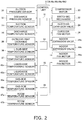
- control unit 8 is configured in such a way that it can perform the air conditioning operations (the cooling operation and the heating operation) by controlling the various devices and valves 20, 22, 24, 26, 41a, 41b, 44a, and 44b on the basis of these detection signals and so forth. Furthermore, here, the control unit 8 mainly has a capacity controlling part 81, an indoor controlling part 82, a target refrigerant temperature mode setting part 83, and a target refrigerant temperature changing part 84.
- the capacity controlling part 81 is a part that controls the air conditioning capacity of the outdoor unit 2 in such a way that an evaporation temperature Te or a condensation temperature Tc of the refrigerant in the refrigerant circuit 10 becomes a target evaporation temperature Tes or a target condensation temperature Tcs.
- the indoor controlling part 82 is a part that controls the devices and valves 41a, 41b, 44a, and 44b of the indoor units 4a and 4b in such a way that the room temperatures Tra and Trb of the air conditioned spaces targeted by the indoor units 4a and 4b become set temperatures Tras and Trbs that are target values of the room temperatures Tra and Trb.
- the target refrigerant temperature mode setting part 83 is a part for setting modes relating to the target evaporation temperature Tes and the target condensation temperature Tcs, such as setting whether to change or fix the target evaporation temperature Tes or the target condensation temperature Tcs.
- the target refrigerant temperature changing part 84 is a part for changing or fixing the target evaporation temperature Tes and the target condensation temperature Tcs in accordance with the mode that has been set by the target refrigerant temperature mode setting part 83.
- FIG. 2 is a control block diagram of the air conditioning apparatus 1.
- the air conditioning apparatus 1 has the refrigerant circuit 10 that is configured as a result of the plural (here, two) indoor units 4a and 4b being connected to the outdoor unit 2. Additionally, in the air conditioning apparatus 1, the following air conditioning operations and control are performed by the control unit 8.
- the switching mechanism 22 When a cooling operation command is given from the remote controllers 49a and 49b, the switching mechanism 22 is switched to a radiation operating state (the state indicated by the solid lines of the switching mechanism 22 in FIG. 1 ), and the compressor 21, the outdoor fan 25, and the indoor fans 43a and 43b start up.
- the low-pressure gas refrigerant in the refrigerant circuit 10 is sucked into the compressor 21, is compressed, and becomes high-pressure gas refrigerant.
- the high-pressure gas refrigerant is sent via the switching mechanism 22 to the outdoor heat exchanger 23.
- the high-pressure gas refrigerant that has been sent to the outdoor heat exchanger 23 condenses and becomes high-pressure liquid refrigerant as a result of exchanging heat with the outdoor air supplied by the outdoor fan 25 and being cooled in the outdoor heat exchanger 23 functioning as a radiator of the refrigerant.
- the high-pressure liquid refrigerant is sent via the outdoor expansion valve 24 and the liquid refrigerant connection pipe 6 from the outdoor unit 2 to the indoor units 4a and 4b.
- the high-pressure liquid refrigerant that has been sent to the indoor units 4a and 4b has its pressure reduced by the indoor expansion valves 41a and 41b and becomes low-pressure refrigerant in a gas-liquid two-phase state.
- the low-pressure refrigerant in the gas-liquid two-phase state is sent to the indoor heat exchangers 42a and 42b.
- the low-pressure refrigerant in the gas-liquid two-phase state that has been sent to the indoor heat exchangers 42a and 42b evaporates and becomes low-pressure gas refrigerant as a result of exchanging heat with the room air supplied by the indoor fans 43a and 43b and being heated in the indoor heat exchangers 42a and 42b functioning as evaporators of the refrigerant.
- the low-pressure gas refrigerant is sent via the gas refrigerant connection pipe 7 from the indoor units 4a and 4b to the outdoor unit 2.
- the low-pressure gas refrigerant that has been sent to the outdoor unit 2 is sucked via the switching mechanism 22 back into the compressor 21.
- the switching mechanism 22 When a heating operation command is given from the remote controllers 49a and 49b, the switching mechanism 22 is switched to an evaporation operating state (the state indicated by the dashed lines of the switching mechanism 22 in FIG. 1 ), and the compressor 21, the outdoor fan 25, and the indoor fans 43a and 43b start up.
- the low-pressure gas refrigerant in the refrigerant circuit 10 is sucked into the compressor 21, is compressed, and becomes high-pressure gas refrigerant.
- the high-pressure gas refrigerant is sent via the switching mechanism 22 and the gas refrigerant connection pipe 7 from the outdoor unit 2 to the indoor units 4a and 4b.
- the high-pressure gas refrigerant that has been sent to the indoor units 4a and 4b is sent to the indoor heat exchangers 42a and 42b.
- the high-pressure gas refrigerant that has been sent to the indoor heat exchangers 42a and 42b condenses and becomes high-pressure liquid refrigerant as a result of exchanging heat with the room air supplied by the indoor fans 43a and 43b and being cooled in the indoor heat exchangers 42a and 42b functioning as radiators of the refrigerant.
- the high-pressure liquid refrigerant has its pressure reduced by the indoor expansion valves 41a and 41b.
- the refrigerant whose pressure has been reduced by the indoor expansion valves 41a and 41b is sent via the liquid refrigerant connection pipe 6 from the indoor units 4a and 4b to the outdoor unit 2.
- the refrigerant that has been sent to the outdoor unit 2 is sent to the outdoor expansion valve 24, has its pressure reduced by the outdoor expansion valve 24, and becomes low-pressure refrigerant in a gas-liquid two-phase state.
- the low-pressure refrigerant in the gas-liquid two-phase state is sent to the outdoor heat exchanger 23.
- the low-pressure refrigerant in the gas-liquid two-phase state that has been sent to the outdoor heat exchanger 23 evaporates and becomes low-pressure gas refrigerant as a result of exchanging heat with the outdoor air supplied by the outdoor fan 25 and being heated in the outdoor heat exchanger 23 functioning as an evaporator of the refrigerant.
- the low-pressure gas refrigerant is sucked via the switching mechanism 22 back into the compressor 21.
- the air conditioning capacity of the outdoor unit 2 is controlled in such a way that the evaporation temperature Te or the condensation temperature Tc of the refrigerant in the refrigerant circuit 10 becomes the target evaporation temperature Tes or the target condensation temperature Tcs.
- the devices and valves 41a, 41b, 44a, and 44b of the indoor units 4a and 4b are controlled in such a way that the room temperatures Tra and Trb associated with the indoor units 4a and 4b become the set temperatures Tras and Trbs of the room temperatures associated with the indoor units 4a and 4b.
- the setting of the set temperatures Tras and Trbs of the room temperatures associated with the indoor units 4a and 4b is performed by the remote controllers 49a and 49b. Furthermore, the control of the outdoor unit 2 is performed by the capacity controlling part 81, which is configured by the outdoor-side control unit 38 of the control unit 8, and the control of the indoor units 4a and 4b is performed by the indoor controlling part 82, which is configured by the indoor-side control units 48a and 48b of the control unit 8.
- the indoor controlling part 82 of the control unit 8 controls the opening degrees of the indoor expansion valves 41a and 41b in such a way that degrees of superheating SHra and SHrb of the refrigerant in the outlets of the indoor heat exchangers 42a and 42b become target degrees of superheating SHras and SHrbs (hereinafter this control will be called "degree of superheating control by indoor expansion valves").
- the degrees of superheating SHra and SHrb are calculated from the suction pressure Ps detected by the suction pressure sensor 31 and the temperatures Trga and Trgb of the refrigerant on the gas sides of the indoor heat exchangers 42a and 42b detected by the gas-side temperature sensors 46a and 46b. More specifically, first, the suction pressure Ps is converted into the saturation temperature of the refrigerant to obtain the evaporation temperature Te, which is a state quantity that is equivalent to the evaporation pressure Pe in the refrigerant circuit 10.
- evaporation pressure Pe means a pressure representing the low-pressure refrigerant flowing from the outlets of the indoor expansion valves 41a and 41b via the indoor heat exchangers 42a and 42b to the suction side of the compressor 21 during the cooling operation. Additionally, the degrees of superheating SHra and SHrb are obtained by subtracting the evaporation temperature Te from the temperatures Trga and Trgb of the refrigerant on the gas sides of the indoor heat exchangers 42a and 42b.
- the capacity controlling part 81 of the control unit 8 controls the operating capacity of the compressor 21 in such a way that the evaporation temperature Te corresponding to the evaporation pressure Pe in the refrigerant circuit 10 becomes closer to the target evaporation temperature Tes (hereinafter this control will be called “evaporation temperature control by compressor”).
- the control of the operating capacity of the compressor 21 is performed by changing the frequency of the compressor motor 20.
- the evaporation temperature Te is used as the state quantity that is controlled, but the state quantity that is controlled may also be the evaporation pressure Pe. In this case, it suffices to use a target evaporation pressure Pes corresponding to the target evaporation temperature Tes. That is, "evaporation pressure Pe" and “evaporation temperature Te”, and “target evaporation pressure Pes” and “target evaporation temperature Tes”, mean substantially the same state quantities even though the wordings themselves are different.
- the degree of superheating control by the indoor expansion valves 41a and 41b and the evaporation temperature control by the compressor 21 are performed as the basic control. Additionally, in the air conditioning apparatus 1, it is ensured by this basic control of the cooling operation that the room temperatures Tra and Trb associated with the indoor units 4a and 4b become the set temperatures Tras and Trbs of the room temperatures associated with the indoor units 4a and 4b.
- the indoor controlling part 82 of the control unit 8 controls the opening degrees of the indoor expansion valves 41a and 41b in such a way that degrees of subcooling SCra and SCrb of the refrigerant in the outlets of the indoor heat exchangers 42a and 42b become target degrees of subcooling SCras and SCrbs (hereinafter this control will be called "degree of subcooling control by indoor expansion valves").
- the degrees of subcooling SCra and SCrb are calculated from the discharge pressure Pd detected by the discharge pressure sensor 32 and the temperatures Trla and Trlb of the refrigerant on the liquid sides of the indoor heat exchangers 42a and 42b detected by the liquid-side temperature sensors 45a and 45b. More specifically, first, the discharge pressure Pd is converted into the saturation temperature of the refrigerant to obtain the condensation temperature Tc, which is a state quantity that is equivalent to the condensation pressure Pc in the refrigerant circuit 10.
- condensation pressure Pc means a pressure representing the high-pressure refrigerant flowing from the discharge side of the compressor 21 via the indoor heat exchangers 42a and 42b to the indoor expansion valves 41a and 41b during the heating operation.
- the degrees of subcooling SCra and SCrb are obtained by subtracting the temperatures Trla and Trlb of the refrigerant on the liquid sides of the indoor heat exchangers 42a and 42b from the condensation temperature Tc.
- the capacity controlling part 81 of the control unit 8 controls the operating capacity of the compressor 21 in such a way that the condensation temperature Tc corresponding to the condensation pressure Pc in the refrigerant circuit 10 becomes closer to the target condensation temperature Tcs (hereinafter this control will be called “condensation temperature control by compressor”).
- the control of the operating capacity of the compressor 21 is performed by changing the frequency of the compressor motor 20.
- the condensation temperature Tc is used as the state quantity that is controlled, but the state quantity that is controlled may also be the condensation pressure Pc. In this case, it suffices to use a target condensation pressure Pcs corresponding to the target condensation temperature Tcs. That is, “condensation pressure Pc" and “condensation temperature Tc”, and “target condensation pressure Pcs” and “target condensation temperature Tcs”, mean substantially the same state quantities even though the wordings themselves are different.
- the degree of subcooling control by the indoor expansion valves 41a and 41b and the condensation temperature control by the compressor 21 are performed as the basic control. Additionally, in the air conditioning apparatus 1, it is ensured by this basic control of the heating operation that the room temperatures Tra and Trb associated with the indoor units 4a and 4b become the set temperatures Tras and Trbs of the room temperatures associated with the indoor units 4a and 4b.
- the thermostat control means setting a thermostat temperature range with respect to the set temperatures Tras and Trbs of the indoor units 4a and 4b and performing indoor thermostat OFF, indoor thermostat ON, outdoor thermostat OFF, and outdoor thermostat ON.
- indoor thermostat OFF means suspending, in a case where the room temperature associated with an indoor unit performing an air conditioning operation has become the set temperature, the air conditioning operation of the corresponding indoor unit. That is, the indoor expansion valve of the corresponding indoor unit is closed to ensure that the refrigerant does not flow to the indoor heat exchanger.
- Indoor thermostat ON means resuming, in a case where the room temperature associated with an indoor unit in an indoor thermostat OFF state has deviated from the thermostat temperature range, the air conditioning operation of the corresponding indoor unit.
- the indoor expansion valve of the corresponding indoor unit is opened (i.e., the degree of superheating control or the degree of subcooling control by the indoor expansion valve is performed) to ensure that the refrigerant flows to the indoor heat exchanger.
- Outdoor thermostat OFF means stopping the compressor 21 in a case where all the indoor units performing an air conditioning operation have switched to an indoor thermostat OFF state. Because of this, the flow of the refrigerant in the refrigerant circuit 10 stops, and the air conditioning apparatus 1 switches to a state in which the air conditioning operations are all substantially stopped even though an air conditioning operation command is being given.
- “Outdoor thermostat ON” means restarting the compressor 21 in a case where, in the outdoor thermostat OFF state, at least one indoor unit has switched to an indoor thermostat ON state.
- the refrigerant flows in the refrigerant circuit 10, and the air conditioning apparatus 1 switches to a state in which the air conditioning operations are resumed.
- “indoor thermostat OFF” and “indoor thermostat ON” are performed by the indoor controlling part 82 of the control unit 8
- “outdoor thermostat OFF” and “outdoor thermostat ON” are performed by the capacity controlling part 81 of the control unit 8.
- the air conditioning apparatus 1 When the air conditioning apparatus 1 performs the air conditioning operations (the cooling operation and the heating operation) accompanied by the thermostat control described above, the room temperatures Tra and Trb associated with the indoor units 4a and 4b are controlled in such a way as to become the set temperatures Tras and Trbs of the room temperatures associated with the indoor units 4a and 4b.
- the air conditioning apparatus it is conceivable to configure the air conditioning apparatus to change the target evaporation temperature Tes and the target condensation temperature Tcs in accordance with the air conditioning load characteristics of the building, like in patent document 1. That is, it is conceivable for the air conditioning apparatus to lower, during the cooling operation, the target evaporation temperature Tes the larger the temperature difference is between the set temperatures Tras and Trbs and the outdoor temperature Ta and to raise, during the heating operation, the target condensation temperature Tcs the larger the temperature difference is between the set temperatures Tras and Trbs and the outdoor temperature Ta.
- the air conditioning apparatus changes the target evaporation temperature Tes or the target condensation temperature Tcs in this way, in a case where the air conditioning capacity requirement from the indoor units 4a and 4b is small, the target evaporation temperature Tes becomes higher and the target condensation temperature Tcs becomes lower, so an excess of the air conditioning capacity of the outdoor unit 2 is suppressed. Because of this, the frequency with which the indoor units 4a and 4b and the compressor 21 alternate between being operated and being stopped-that is, indoor thermostat ON / indoor thermostat OFF, outdoor thermostat ON / outdoor thermostat OFF-can be reduced so that energy conservation can be improved.
- the control unit 8 is disposed with the target refrigerant temperature mode setting part 83 for setting modes relating to the target evaporation temperature Tes or the target condensation temperature Tcs, such as setting whether to change or fix the target evaporation temperature Tes and the target condensation temperature Tcs.
- the target refrigerant temperature mode setting part 83 is a memory disposed in the outdoor-side control unit 38 of the control unit 8 and can set the target refrigerant temperature mode to various modes relating to the target evaporation temperature Tes or the target condensation temperature Tcs by communication from an external device for performing various control settings of the air conditioning apparatus 1.
- the target refrigerant temperature mode setting part 83 is not limited to the part described above, and it suffices for the target refrigerant temperature mode setting part 83 to be a part that can set the target refrigerant temperature mode to various modes relating to the target evaporation temperature Tes and the target condensation temperature Tcs, such as, for example, a DIP switch disposed in the outdoor-side control unit 38.
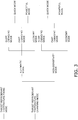
- FIG. 3 is a drawing showing the various modes relating to the target evaporation temperature Tes and the target condensation temperature Tcs that are settable.
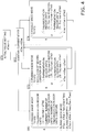
- FIG. 4 is a flowchart showing control for correcting the target evaporation temperature Tes in a slow changing mode and a fast changing mode (a quick mode and a powerful mode).
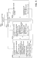
- FIG. 5 is a flowchart showing control for correcting the target condensation temperature Tcs in the slow changing mode and the fast changing mode (the quick mode and the powerful mode).
- FIG. 6 is a drawing showing temporal changes, from the start of the cooling operation, in the target evaporation temperature Tes, room temperatures Tr, and efficiency in a target refrigerant temperature fixing mode and a target refrigerant temperature changing mode (the slow changing mode, the quick mode, and the powerful mode).
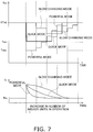
- FIG. 7 is a drawing showing temporal changes in the target evaporation temperature Tes and the room temperatures Tr in the slow changing mode, the quick mode, and the powerful mode in a case where the number of indoor units in operation has increased during the cooling operation.
- FIG. 7 is a drawing showing temporal changes in the target evaporation temperature Tes and the room temperatures Tr in the slow changing mode, the quick mode, and the powerful mode in a case where the number of indoor units in operation has increased during the cooling operation.
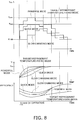
- FIG. 8 is a drawing showing temporal changes, from the start of the heating operation, in the target condensation temperature Tcs, the room temperatures Tr, and efficiency in the target refrigerant temperature fixing mode and the target refrigerant temperature changing mode (the slow changing mode, the quick mode, and the powerful mode).
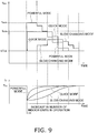
- FIG. 9 is a drawing showing temporal changes in the target condensation temperature Tcs and the room temperatures Tr in the slow changing mode, the quick mode, and the powerful mode in a case where the number of indoor units in operation has increased during the heating operation.
- the target refrigerant temperature fixing mode that fixes the target evaporation temperature Tes or the target condensation temperature Tcs.
- the control unit 8 is disposed with the target refrigerant temperature changing part 84 serving as a part for changing or fixing the target evaporation temperature Tes and the target condensation temperature Tcs in accordance with the mode that has been set by the target refrigerant temperature mode setting part 83. For this reason, when the mode is set to the target refrigerant temperature fixing mode by the target refrigerant temperature mode setting part 83, the target refrigerant temperature changing part 84 fixes the target evaporation temperature Tes in the cooling operation to the predetermined value and fixes the target condensation temperature Tcs in the heating operation to the predetermined value.
- the target evaporation temperature Tes is fixed to a maximum capacity evaporation temperature Tem (e.g., 6°C) corresponding to a case where the air conditioning (cooling) capacity of the outdoor unit 2 is at 100% capacity.
- the target condensation temperature Tcs is fixed to a maximum capacity condensation temperature Tcm (e.g., 46°C) corresponding to a case where the air conditioning (heating) capacity of the outdoor unit 2 is at 100% capacity.
- the target evaporation temperature Tes or the target condensation temperature Tcs is constantly fixed to the maximum capacity evaporation temperature Tem or the maximum capacity condensation temperature Tcm.
- the air conditioning operations can be performed in a state in which priority is constantly given to comfort.
- it becomes easy for efficiency to drop because it is easy for the air conditioning capacity of the outdoor unit 2 to become excessive.
- the target refrigerant temperature changing mode that changes the target evaporation temperature Tes or the target condensation temperature Tcs.
- the target evaporation temperature Tes is changed as a result of a reference target evaporation temperature KTeb serving as a reference value of the target evaporation temperature Tes in the cooling operation being set automatically or by the user and an evaporation temperature correction value KTec being added to the reference target evaporation temperature KTeb.
- the target refrigerant temperature changing mode has two modes (a fast changing mode and a slow changing mode) in which the degree of control trackability is different. Additionally, the fast changing mode and the slow changing mode are set by the target refrigerant temperature mode setting part 83. Furthermore, as shown in FIG. 3 , the fast changing mode has two modes (a powerful mode and a quick mode) in which the degree of control trackability is further different. Additionally, the powerful mode and the quick mode are set by the target refrigerant temperature mode setting part 83.
- the target refrigerant temperature changing mode has two modes (an automatic mode and a high-sensitivity mode) in which the way of setting the reference target evaporation temperature KTeb or the reference target condensation temperature KTcb is different. Additionally, the automatic mode or the high-sensitivity mode is set, together with the fast changing mode and the slow changing mode, by the target refrigerant temperature mode setting part 83. Moreover, as shown in FIG.
- the target refrigerant temperature changing mode has an economy mode in which the reference target evaporation temperature KTeb or the reference target condensation temperature KTcb that has been set in the high-sensitivity mode is set as the target evaporation temperature Tes or the target condensation temperature Tcs without a correction being made to that reference target evaporation temperature KTeb or that reference target condensation temperature KTcb. Additionally, the economy mode is set, together with the automatic mode or the high-sensitivity mode, by the target refrigerant temperature mode setting part 83.
- the mode can be set to either of the target refrigerant temperature changing mode and the target refrigerant temperature fixing mode by the target refrigerant temperature mode setting part 83. Additionally, when the mode is set to the target refrigerant temperature changing mode, priority can be given to energy conservation as described below, and when the mode is set to the target refrigerant temperature fixing mode, priority can be given to comfort as described above. Because of this, here, priority can be given to energy conservation or priority can be given to comfort according to the preference of the user.
- the reference target evaporation temperature KTeb or the reference target condensation temperature KTcb is set in accordance with the outdoor temperature Ta of the outside space where the outdoor unit 2 is disposed. Specifically, when the mode is set to the automatic mode by the target refrigerant temperature mode setting part 83, the reference target evaporation temperature KTeb or the reference target condensation temperature KTcb is set on the basis of a function of the outdoor temperature Ta. In the cooling operation, more air conditioning (cooling) capacity tends to be required the higher the outdoor temperature Ta is, so the reference target evaporation temperature KTeb is set on the basis of a function in which the reference target evaporation temperature KTeb becomes lower as the outdoor temperature Ta becomes higher.
- the reference target condensation temperature KTcb is set on the basis of a function in which the reference target condensation temperature KTcb becomes higher as the outdoor temperature Ta becomes lower.
- the target refrigerant temperature changing part 84 automatically sets the reference target evaporation temperature KTeb in the cooling operation to a temperature value obtained on the basis of the above-described function and the outdoor temperature Ta and automatically sets the reference target condensation temperature KTcb in the heating operation to a temperature value obtained on the basis of the above-described function and the outdoor temperature Ta.
- the target refrigerant temperature changing part 84 changes the target evaporation temperature Tes and the target condensation temperature Tcs by changing the reference target evaporation temperature KTeb and the reference target condensation temperature KTcb in accordance with the outdoor temperature Ta and at the same time further making a correction according to the slow changing mode and the fast changing mode described below.
- the evaporation temperature correction value KTec is changed as shown in steps ST1 to ST4 of FIG. 4 . Additionally, the target evaporation temperature Tes is changed by making a correction that adds the evaporation temperature correction value KTec to the reference target evaporation temperature KTeb.
- the changing of the evaporation temperature correction value KTec in the slow changing mode and the control that corrects the target evaporation temperature Tes by adding the evaporation temperature correction value KTec to the reference target evaporation temperature KTeb are performed by the target refrigerant temperature changing part 84.
- step ST1 an initial value setting of the evaporation temperature correction value KTec is performed.
- step ST2 After performing processing that maintains the current state in step ST2, the target refrigerant temperature changing part 84 moves to the processing of step ST3 or step ST4.
- step ST3 assuming that a first amount of waiting time t1 (e.g., 10 minutes) has passed since the move to step ST2 and that a moving condition of step ST5 described later has not been met, the target refrigerant temperature changing part 84 performs slow changing control that changes the target evaporation temperature Tes in accordance with the temperature differences (Tr - Trs) between the room temperatures Tra and Trb (hereinafter called “the room temperatures Tr” by omitting the letters "a” and “b”) of the air conditioned spaces targeted by the indoor units 4a and 4b and the set temperatures Tras and Trbs (hereinafter called “the set temperatures Trs” by omitting the letters "a” and "b”) that are target values of the room temperatures Tr.
- the room temperatures Tr by omitting the letters "a” and “b
- the target refrigerant temperature changing part 84 reduces the evaporation temperature correction value KTec by subtracting a correction value ⁇ Tec1 (e.g., 0.5°C) from the current evaporation temperature correction value KTec and adds the evaporation temperature correction value KTec to the reference target evaporation temperature KTeb to thereby correct the target evaporation temperature Tes in such a way that the target evaporation temperature Tes becomes lower.
- a correction value ⁇ Tec1 e.g., 0.5°C
- the target refrigerant temperature changing part 84 performs slow changing control that corrects the target evaporation temperature Tes in such a way that the target evaporation temperature Tes becomes lower.
- the target refrigerant temperature changing part 84 determines that the temperature differences (Tr - Trs) meet the condition that it is necessary to lower the target evaporation temperature Tes.
- step ST4 assuming that the first amount of waiting time t1 (e.g., 10 minutes) has passed since the move to step ST2, the target refrigerant temperature changing part 84 performs slow changing control that changes the target evaporation temperature Tes in accordance with the temperature differences (Tr - Trs) between the room temperatures Tr of the air conditioned spaces targeted by the indoor units 4a and 4b and the set temperatures Trs that are target values of the room temperatures Tr.
- the target refrigerant temperature changing part 84 performs slow changing control that changes the target evaporation temperature Tes in accordance with the temperature differences (Tr - Trs) between the room temperatures Tr of the air conditioned spaces targeted by the indoor units 4a and 4b and the set temperatures Trs that are target values of the room temperatures Tr.
- the target refrigerant temperature changing part 84 increases the evaporation temperature correction value KTec by adding a correction value ⁇ Tec2 (e.g., 1°C) to the current evaporation temperature correction value KTec and adds the evaporation temperature correction value KTec to the reference target evaporation temperature KTeb to thereby correct the target evaporation temperature Tes in such a way that the target evaporation temperature Tes becomes higher.
- a correction value ⁇ Tec2 e.g., 1°C
- (Tr - Trs)max the amount of time t2 (e.g., 5 minutes) before is larger than a predetermined temperature difference ⁇ Tre3 (e.g., 0.5°C)
- the target refrigerant temperature changing part 84 performs slow changing control that corrects the target evaporation temperature Tes in such a way that the target evaporation temperature Tes becomes higher.
- the target refrigerant temperature changing part 84 determines that the temperature differences (Tr - Trs) meet the condition that it is necessary to raise the target evaporation temperature Tes. Furthermore, as a condition of the temperature differences (Tr - Trs), also in a case where (Tr - Trs)max that is a maximum of the temperature differences (Tr - Trs) among the indoor units in an indoor thermostat ON state is equal to or less than a predetermined temperature difference ⁇ Tre4 (e.g., 0.5°C), the target refrigerant temperature changing part 84 performs slow changing control that corrects the target evaporation temperature Tes in such a way that the target evaporation temperature Tes becomes higher.
- a predetermined temperature difference ⁇ Tre4 e.g., 0.5°C
- the target refrigerant temperature changing part 84 determines that the temperature differences (Tr - Trs) meet the condition that it is necessary to raise the target evaporation temperature Tes.
- step ST3 or step ST4 the target refrigerant temperature changing part 84 returns to the processing of step ST2, and thereafter the processing of steps ST2, ST3, and ST4 is repeated.
- the reference target evaporation temperature KTeb is set in accordance with the outdoor temperature Ta by the automatic mode, so the target evaporation temperature Tes that is set as a result of a correction corresponding to the slow changing mode being made to the reference target evaporation temperature KTeb can further improve the degree of energy conservation.
- the maximum value of the temperature differences between the room temperatures Tr and the set temperatures Trs among the indoor units in operation is used as a condition for changing the target evaporation temperature Tes.
- the target evaporation temperature Tes is changed in accordance with the indoor unit in which the largest air conditioning (cooling) capacity is required. Because of this, here, the target evaporation temperature Tes can be promptly changed and control trackability can be improved.
- the condensation temperature correction value KTcc is changed as shown in steps ST11 to ST 14 of FIG. 5 .
- the target condensation temperature Tcs is changed by making a correction that adds the condensation temperature correction value KTcc to the reference target condensation temperature KTcb.
- the changing of the condensation temperature correction value KTcc and the control that corrects the target condensation temperature Tcs by adding the condensation temperature correction value KTcc to the reference target condensation temperature KTcb are performed by the target refrigerant temperature changing part 84.
- step ST11 an initial value setting of the condensation temperature correction value KTcc is performed.
- the target refrigerant temperature changing part 84 moves to the processing of step ST13 or step ST14.
- step ST13 assuming that a first amount of waiting time t1 (e.g., 10 minutes) has passed since the move to step ST12 and that a moving condition of step ST15 described later has not been met, the target refrigerant temperature changing part 84 performs slow changing control that changes the target condensation temperature Tcs in accordance with the temperature differences (Trs - Tr) between the room temperatures Tr of the air conditioned spaces targeted by the indoor units 4a and 4b and the set temperatures Trs that are target values of the room temperatures Tr.
- t1 e.g. 10 minutes
- the target refrigerant temperature changing part 84 increases the condensation temperature correction value KTcc by adding a correction value ⁇ Tcc1 (e.g., 1°C) to the current condensation temperature correction value KTcc and adds the condensation temperature correction value KTcc to the reference target condensation temperature KTcb to thereby correct the target condensation temperature Tcs in such a way that the target condensation temperature Tcs becomes higher.
- a correction value ⁇ Tcc1 e.g., 1°C
- (Trs - Tr)max an amount of time t2 (e.g., 5 minutes) before is equal to or less than a predetermined temperature difference ⁇ Trc1 (e.g., 0.2°C)
- the target refrigerant temperature changing part 84 performs slow changing control that corrects the target condensation temperature Tcs in such a way that the target condensation temperature Tcs becomes higher.
- the target refrigerant temperature changing part 84 determines that the temperature differences (Trs - Tr) meet the condition that it is necessary to raise the target condensation temperature Tcs. Furthermore, as a condition of the temperature differences (Trs - Tr), also in a case where (Trs - Tr)max that is a maximum of the temperature differences (Trs - Tr) among the indoor units in an indoor thermostat ON state is larger than a predetermined temperature difference ⁇ Trc2 (e.g., 3°C), the target refrigerant temperature changing part 84 performs slow changing control that corrects the target condensation temperature Tcs in such a way that the target condensation temperature Tcs becomes higher. That is, in a case where the room temperatures Tr are lower than the set temperatures Trs, the target refrigerant temperature changing part 84 determines that the temperature differences (Trs - Tr) meet the condition that it is necessary to raise the target condensation temperature Tcs.
- a predetermined temperature difference ⁇ Trc2 e.g. 3°C
- step ST14 assuming that the first amount of waiting time t1 (e.g., 10 minutes) has passed since the move to step ST12, the target refrigerant temperature changing part 84 performs slow changing control that changes the target condensation temperature Tcs in accordance with the temperature differences (Trs - Tr) between the room temperatures Tr of the air conditioned spaces targeted by the indoor units 4a and 4b and the set temperatures Trs that are target values of the room temperatures Tr.
- the target refrigerant temperature changing part 84 performs slow changing control that changes the target condensation temperature Tcs in accordance with the temperature differences (Trs - Tr) between the room temperatures Tr of the air conditioned spaces targeted by the indoor units 4a and 4b and the set temperatures Trs that are target values of the room temperatures Tr.
- the target refrigerant temperature changing part 84 reduces the condensation temperature correction value KTcc by subtracting a correction value ⁇ Tcc2 (e.g., 1.5°C) from the current condensation temperature correction value KTcc and adds the condensation temperature correction value KTcc to the reference target condensation temperature KTcb to thereby correct the target condensation temperature Tcs in such a way that the target condensation temperature Tcs becomes lower.
- a correction value ⁇ Tcc2 e.g., 1.5°C
- the target refrigerant temperature changing part 84 performs slow changing control that corrects the target condensation temperature Tcs in such a way that the target condensation temperature Tcs becomes lower.
- the target refrigerant temperature changing part 84 determines that the temperature differences (Trs - Tr) meet the condition that it is necessary to lower the target condensation temperature Tcs.
- step ST13 or step ST14 the target refrigerant temperature changing part 84 returns to the processing of step ST12, and thereafter the processing of steps ST12, ST13, and ST14 is repeated.
- the target condensation temperature Tcs is slowly changed as shown in FIG. 8 .
- basically an excess of the air conditioning (heating) capacity of the outdoor unit 2 can be suppressed, efficiency is more easily improved, and energy conservation can be improved.
- the reference target condensation temperature KTcb is set in accordance with the outdoor temperature Ta by the automatic mode, so the target condensation temperature Tcs that is set as a result of a correction corresponding to the slow changing mode being made to the reference target condensation temperature KTcb can further improve the degree of energy conservation.
- the maximum value of the temperature differences between the room temperatures Tr and the set temperatures Trs among the indoor units in operation is used as a condition for changing the target condensation temperature Tcs. For this reason, the target condensation temperature Tcs is changed in accordance with the indoor unit in which the largest air conditioning (heating) capacity is required. Because of this, here, the target condensation temperature Tcs can be promptly changed and control trackability can be improved.
- the mode is set to the automatic mode and is set to the fast changing mode by the target refrigerant temperature mode setting part 83, during the cooling operation, the same slow changing control resulting from steps ST1 to ST4 as in the slow changing mode described above is performed, and in a case where the temperature differences (Tr - Trs) have exceeded a threshold temperature difference and the number of indoor units in operation has increased, as shown in step ST5 of FIG. 4 , fast changing control is performed where the evaporation temperature correction value KTec and the target evaporation temperature Tes are forcibly changed to fast tracking evaporation temperatures (here, the maximum capacity evaporation temperature Tem and a lowest evaporation temperature Teex).
- step ST5 assuming that the first amount of waiting time t1 (e.g., 10 minutes) has passed since the move to step ST2, in a case where (Tr - Trs)max that is a maximum of the temperature differences (Tr - Trs) among the indoor units in an indoor thermostat ON state is larger than the predetermined temperature difference ⁇ Tre2 (e.g., 3°C) serving as a threshold temperature difference and the current number of indoor units in an indoor thermostat ON state is larger than the number of indoor units in an indoor thermostat ON state an amount of time t3 (e.g., 30 seconds) before, the target refrigerant temperature changing part 84 performs fast changing control that corrects the target evaporation temperature Tes in such a way as to rapidly lower the target evaporation temperature Tes.
- ⁇ Tre2 e.g., 3°C
- a large air conditioning (cooling) capacity becomes necessary in the outdoor unit 2, and the target refrigerant temperature changing part 84 determines that this meets the condition that it is necessary to rapidly lower the target evaporation temperature Tes.
- the fast changing mode has a powerful mode and a quick mode. Additionally, in the powerful mode, in the case meeting the condition that it is necessary to rapidly lower the target evaporation temperature Tes, powerful changing control is performed which changes the evaporation temperature correction value KTec by subtracting the reference target evaporation temperature KTeb from the current evaporation temperature correction value KTec and adding a fast tracking evaporation temperature (here, a lowest evaporation temperature Teex exceeding the maximum capacity evaporation temperature Tem) and adds the evaporation temperature correction value Tec to the reference target evaporation temperature KTeb to thereby forcibly change the target evaporation temperature Tes to the lowest evaporation temperature Teex (e.g., 3°C) serving as the fast tracking evaporation temperature.
- a fast tracking evaporation temperature here, a lowest evaporation temperature Teex exceeding the maximum capacity evaporation temperature Tem
- the powerful mode is a mode that allows the target evaporation temperature Tes to be changed to the lowest evaporation temperature Teex exceeding the maximum capacity evaporation temperature Tem.
- quick changing control is performed which changes the evaporation temperature correction value KTec by subtracting the reference target evaporation temperature KTeb from the current evaporation temperature correction value KTec and adding a fast tracking evaporation temperature (here, a maximum capacity evaporation temperature Tem) and adds the evaporation temperature correction value KTec to the reference target evaporation temperature KTeb to thereby forcibly change the target evaporation temperature Tes to the maximum capacity evaporation temperature Tem (e.g., 6°C) serving as the fast tracking evaporation temperature.
- a fast tracking evaporation temperature here, a maximum capacity evaporation temperature Tem
- the quick mode is a mode that does not allow the target evaporation temperature Tes to be changed to the lowest evaporation temperature Teex.
- the changing of the evaporation temperature correction value KTec in the fast changing mode (the powerful mode and the quick mode) and the control that corrects the target evaporation temperature Tes by adding the evaporation temperature correction value KTec to the reference target evaporation temperature KTeb are also performed by the target refrigerant temperature changing part 84.
- step ST5 After performing the processing of step ST5, the target refrigerant temperature changing part 84 returns to the processing of step ST2, and thereafter the processing of steps ST2, ST3, ST4, and ST5 is repeated.
- the target evaporation temperature Tes is changed in such a way that the room temperatures Tr reach the set temperatures Trs in a shorter amount of time compared to the case resulting from the slow changing mode (i.e., in the slow changing mode, the target evaporation temperature Tes is changed in such a way that the room temperatures Tr reach the set temperatures Trs in a longer amount of time than in the fast changing mode).
- the mode by setting the mode to the fast changing mode, control trackability can be improved compared to a case where the mode is set to the slow changing mode. Because of this, here, by setting the mode to the target refrigerant temperature changing mode, priority can be given to energy conservation, and at the same time the degree of control trackability can be changed according to the preference of the user.
- the target evaporation temperature Tes is slowly changed by step ST3. For this reason, basically an excess of the air conditioning (cooling) capacity of the outdoor unit 2 can be suppressed.
- the target evaporation temperature Tes is changed to a fast tracking evaporation temperature (here, the maximum capacity evaporation temperature Tem and the lowest evaporation temperature Teex) by performing fast changing control. Because of this, here, by changing the target evaporation temperature Tes, energy conservation can be improved, and sufficient control trackability can be obtained even in a case where the number of indoor units in operation increases.
- the reference target evaporation temperature KTeb is set in accordance with the outdoor temperature Ta by the automatic mode, so the target evaporation temperature Tes that is set as a result of a correction corresponding to the fast changing mode being made to the reference target evaporation temperature KTeb can further improve the degree of energy conservation.
- the maximum value of the temperature differences between the room temperatures Tr and the set temperatures Trs among the indoor units in operation is used as a condition for changing the target evaporation temperature Tes.
- the target evaporation temperature Tes is changed in accordance with the indoor unit in which the largest air conditioning (cooling) capacity is required. Because of this, here, the target evaporation temperature Tes can be promptly changed and control trackability can be improved.
- the fast changing mode can be set to either of two modes (control)-the powerful mode (powerful changing control) and the quick mode (quick changing control)-in which the degree of control trackability is further different.
- the mode when the mode is set to the powerful mode, the target evaporation temperature Tes is allowed to be changed to the lowest evaporation temperature Teex exceeding the maximum capacity evaporation temperature Tem, so as shown in FIG. 7 , control trackability is further improved compared to a case where the mode is set to the quick mode or a case where the mode is set to the target refrigerant temperature fixing mode. Because of this, here, by setting the mode to the fast changing mode, control trackability can be improved, and at the same time the degree of control trackability can be further changed according to the preference of the user.
- the mode is set to the automatic mode and is set to the fast changing mode by the target refrigerant temperature mode setting part 83, during the heating operation, the same slow changing control resulting from steps ST11 to ST14 as in the slow changing mode described above is performed, and in a case where the temperature differences (Trs - Tr) have exceeded the threshold temperature difference and the number of indoor units in operation has increased, as shown in step ST15 of FIG. 5 , fast changing control is performed in which the condensation temperature correction value KTcc and the target condensation temperature Tcs are forcibly changed to fast tracking condensation temperatures (here, the maximum capacity condensation temperature Tcm and a highest condensation temperature Tcex).
- the condensation temperature correction value KTcc and the target condensation temperature Tcs are forcibly changed to fast tracking condensation temperatures (here, the maximum capacity condensation temperature Tcm and a highest condensation temperature Tcex).
- step ST15 assuming that the first amount of waiting time t1 (e.g., 10 minutes) has passed since the move to step ST12, in a case where (Trs - Tr)max that is a maximum of the temperature differences (Trs - Tr) among the indoor units in an indoor thermostat ON state is larger than the predetermined temperature difference ⁇ Trc2 (e.g., 3°C) serving as a threshold temperature difference and the current number of indoor units in an indoor thermostat ON state is larger than the number of indoor units in an indoor thermostat ON state an amount of time t3 (e.g., 30 seconds) before, the target refrigerant temperature changing part 84 performs fast changing control that corrects the target condensation temperature Tcs in such a way as to rapidly raise the target condensation temperature Tcs.
- ⁇ Trc2 e.g., 3°C
- a large air conditioning (heating) capacity becomes necessary in the outdoor unit 2, and the target refrigerant temperature changing part 84 determines that this meets the condition that it is necessary to rapidly raise the target condensation temperature Tcs.
- the fast changing mode has a powerful mode and a quick mode. Additionally, in the powerful mode, in the case meeting the condition that it is necessary to rapidly raise the target condensation temperature Tcs, powerful changing control is performed which changes the condensation temperature correction value KTcc by subtracting the reference target condensation temperature KTcb from the current condensation temperature correction value KTcc and adding a fast tracking condensation temperature (here, a highest condensation temperature Tcex exceeding the maximum capacity condensation temperature Tcm) and adds the condensation temperature correction value KTcc to the reference target condensation temperature KTcb to thereby forcibly change the target condensation temperature Tcs to the highest condensation temperature Tcex (e.g., 49°C) serving as the fast tracking condensation temperature.
- a fast tracking condensation temperature here, a highest condensation temperature Tcex exceeding the maximum capacity condensation temperature Tcm
- the powerful mode is a mode that allows the target condensation temperature Tcs to be changed to the highest condensation temperature Tcex exceeding the maximum capacity condensation temperature Tcm.
- quick changing control is performed which changes the condensation temperature correction value KTcc by subtracting the reference target condensation temperature KTcb from the current condensation temperature correction value KTcc and adding a fast tracking condensation temperature (here, the maximum capacity condensation temperature Tcm) and adds the condensation temperature correction value KTcc to the reference target condensation temperature KTcb to thereby forcibly change the target condensation temperature Tcs to the maximum capacity condensation temperature Tcm (e.g., 46°C) serving as the fast tracking condensation temperature.
- Tcm e.g. 46°C
- the quick mode is a mode that does not allow the target condensation temperature Tcs to be changed to the highest condensation temperature Tcex.
- the changing of the condensation temperature correction value KTcc in the fast changing mode (the powerful mode and the quick mode) and the control that corrects the target condensation temperature Tcs by adding the condensation temperature correction value KTcc to the reference target condensation temperature KTcb are also performed by the target refrigerant temperature changing part 84.
- step ST15 the target refrigerant temperature changing part 84 returns to the processing of step ST12, and thereafter the processing of steps ST12, ST13, ST14, and ST15 is repeated.
- the target condensation temperature Tcs is changed in such a way that the room temperatures Tr reach the set temperatures Trs in a shorter amount of time compared to the case resulting from the slow changing mode (i.e., in the slow changing mode, the target condensation temperature Tcs is changed in such a way that the room temperatures Tr reach the set temperatures Trs in a longer amount of time than in the fast changing mode).
- the mode by setting the mode to the fast changing mode, control trackability can be improved compared to a case where the mode is set to the slow changing mode. Because of this, here, by setting the mode to the target refrigerant temperature changing mode, priority can be given to energy conservation, and at the same time the degree of control trackability can be changed according to the preference of the user.
- the target condensation temperature Tcs is slowly changed by step ST13. For this reason, basically an excess of the air conditioning (heating) capacity of the outdoor unit 2 can be suppressed.
- the target condensation temperature Tcs is changed to a fast tracking condensation temperature (here, the maximum capacity condensation temperature Tcm and the highest condensation temperature Tcex). Because of this, here, by changing the target condensation temperature Tcs, energy conservation can be improved, and sufficient control trackability can be obtained even in a case where the number of indoor units in operation increases.
- the reference target condensation temperature KTcb is set in accordance with the outdoor temperature Ta by the automatic mode, so the target condensation temperature Tcs that is set as a result of a correction corresponding to the fast changing mode being made to the reference target condensation temperature KTcb can further improve the degree of energy conservation.
- the maximum value of the temperature differences between the room temperatures Tr and the set temperatures Trs among the indoor units in operation is used as a condition for changing the target condensation temperature Tcs. For this reason, the target condensation temperature Tcs is changed in accordance with the indoor unit in which the largest air conditioning (heating) capacity is required. Because of this, here, the target condensation temperature Tcs can be promptly changed and control trackability can be improved.
- the fast changing mode can be set to either of two modes (control)-the powerful mode (powerful changing control) and the quick mode (quick changing control)-in which the degree of control trackability is further different.
- the mode when the mode is set to the powerful mode, the target condensation temperature Tcs is allowed to be changed to the highest condensation temperature Tcex exceeding the maximum capacity condensation temperature Tcm, so as shown in FIG. 9 , control trackability is further improved compared to a case where the mode is set to the quick mode or a case where the mode is set to the target refrigerant temperature fixing mode. Because of this, here, by setting the mode to the fast changing mode, control trackability can be improved, and at the same time the degree of control trackability can be further changed according to the preference of the user.
- the reference target evaporation temperature KTeb is set as the target evaporation temperature Tes without a correction being made to the reference target evaporation temperature KTeb that was set in the automatic mode (i.e., only a change corresponding to the outdoor temperature Ta is made).
- the reference target condensation temperature KTcb is set as the target condensation temperature Tcs without a correction being made to the reference target condensation temperature KTcb that was set in the automatic mode (i.e., only a change corresponding to the outdoor temperature Ta is made).
- the mode when the mode is set to the automatic mode of the target refrigerant temperature changing mode, the mode can be set to any of three modes including, in addition to the fast changing mode and the slow changing mode, the economy mode in which the way of correcting the reference target evaporation temperature KTeb or the reference target condensation temperature KTcb that has been set in the automatic mode is different. Additionally, when the mode is set to the economy mode, the target evaporation temperature Tes or the target condensation temperature Tcs is set without a correction being made to the reference target evaporation temperature KTeb or the reference target condensation temperature KTcb, so the degree of control trackability can be brought closest to the preference of the user. Because of this, here, by setting the mode to the automatic mode, the degree of energy conservation can be set, and at the same time the degree of control trackability can be changed according to the preference of the user.
- the user sets the reference target evaporation temperature KTeb or the reference target condensation temperature KTcb.
- the user can set the value of the reference target evaporation temperature KTeb or the reference target condensation temperature KTcb.
- the user can set the reference target evaporation temperature KTeb by selecting any of several temperature values (e.g., 7, 8, 9, 10, and 11°C) that are higher than the maximum capacity evaporation temperature Tem.
- the user can set the reference target condensation temperature KTcb by selecting any of several temperature values (e.g., 41 and 43°C) that are lower than the maximum capacity condensation temperature Tcm.
- the user sets the reference target evaporation temperature KTeb or the reference target condensation temperature KTcb, and the target refrigerant temperature changing part 84 changes the target evaporation temperature Tes or the target condensation temperature Tcs by further making a correction according to the same slow changing mode or the fast changing mode as in the automatic mode or by not making a correction (economy mode).
- the mode when the mode is set to the target refrigerant temperature changing mode by the target refrigerant temperature mode setting part 83, the mode can be set to either of two modes-the automatic mode and the high-sensitivity mode-in which the way of setting the reference target evaporation temperature KTeb or the reference target condensation temperature KTcb is different.
- the reference target evaporation temperature KTeb or the reference target condensation temperature KTcb is set in accordance with the outdoor temperature Ta, so the target evaporation temperature Tes or the target condensation temperature Tcs that is set as a result of a correction corresponding to the fast changing mode or the slow changing mode being made to the reference target evaporation temperature KTeb or the reference target condensation temperature KTcb can further improve the degree of energy conservation compared to a case where the mode is set to the high-sensitivity mode.
- the degree of energy conservation can be set according to the preference of the user. Because of this, here, by setting the mode to the target refrigerant temperature changing mode, priority can be given to energy conservation, and at the same time the degree of energy conservation can be changed according to the preference of the user.
- the evaporation temperature correction value KTec is changed as shown in steps ST1 to ST4 of FIG. 4 . Additionally, the target evaporation temperature Tes is changed by making a correction that adds the evaporation temperature correction value KTec to the reference target evaporation temperature KTeb.
- the condensation temperature correction value KTcc is changed as shown in steps ST11 to ST14 of FIG. 5 .
- the target condensation temperature Tcs is changed by making a correction that adds the condensation temperature correction value KTcc to the reference target condensation temperature KTcb.
- the mode is set to the high-sensitivity mode and is set to the fast changing mode (the powerful mode or the quick mode) by the target refrigerant temperature mode setting part 83, during the cooling operation, the same slow changing control resulting from steps ST1 to ST4 as in the slow changing mode described above is performed, and in a case where the temperature differences (Tr - Trs) have exceeded the threshold temperature difference and the number of indoor units in operation has increased, as shown in step ST5 of FIG.
- fast changing control (powerful changing control or quick changing control) is performed in which the evaporation temperature correction value KTec and the target evaporation temperature Tes are forcibly changed to fast tracking evaporation temperatures (here, the maximum capacity evaporation temperature Tem and the lowest evaporation temperature Teex).
- the mode is set to the high-sensitivity mode and is set to the fast changing mode (the powerful mode or the quick mode) by the target refrigerant temperature mode setting part 83
- the same slow changing control resulting from steps ST11 to ST14 as in the slow changing mode described above is performed, and in a case where the temperature differences (Trs - Tr) have exceeded the threshold temperature difference and the number of indoor units in operation has increased, as shown in step ST15 of FIG. 5 , fast changing control (powerful changing control or quick changing control) is performed in which the condensation temperature correction value KTcc and the target condensation temperature Tcs are forcibly changed to fast tracking condensation temperatures (here, the maximum capacity condensation temperature Tcm and the highest condensation temperature Tcex).
- the reference target evaporation temperature KTeb is set as the target evaporation temperature Tes without a correction being made to the reference target evaporation temperature KTeb that has been set in the high-sensitivity mode (i.e., in contrast to the automatic mode, without even a change corresponding to the outdoor temperature Ta being made).
- the reference target condensation temperature KTcb is set as the target condensation temperature Tcs without a correction being made to the reference target condensation temperature KTcb that has been set in the high-sensitivity mode (i.e., in contrast to the automatic mode, without even a change corresponding to the outdoor temperature Ta being made).
- the mode when the mode is set to the high-sensitivity mode of the target refrigerant temperature changing mode, the mode can be set to any of three modes including, in addition to the fast changing mode and the slow changing mode, the economy mode in which the way of correcting the reference target evaporation temperature KTeb or the reference target condensation temperature KTcb that has been set in the high-sensitivity mode is different. Additionally, when the mode is set to the economy mode, the target evaporation temperature Tes or the target condensation temperature Tcs is set without a correction being made to the reference target evaporation temperature KTeb or the reference target condensation temperature KTcb, so the degree of control trackability can be brought closest to the preference of the user. Because of this, here, by setting the mode to the high-sensitivity mode, the degree of energy conservation can be set, and at the same time the degree of control trackability can be changed according to the preference of the user.
- the target refrigerant temperature changing part 84 determines, every first amount of waiting time t1, whether or not the slow changing control (steps ST3, ST4, ST13, ST14) is necessary and also determines, every first amount of waiting time t1, whether or not the fast changing control (steps ST5, ST15) is necessary. For this reason, both in a case where an increase in the number of indoor units in operation occurs and in a case where this is not so, the target refrigerant temperature changing part 84 can perform control only every first amount of waiting time t1.
- the fast changing control is performed in a case where the number of indoor units in operation increases, so it is preferable to ensure that the fast changing control can be promptly performed.
- the target refrigerant temperature changing part 84 determines whether or not the slow changing control is necessary every time the first amount of waiting time t1 passes and determines whether or not the fast changing control is necessary every time a second amount of waiting time t3, which is shorter than the first amount of waiting time t1, passes.
- the fast changing control can be performed more frequently compared to the slow changing control, and the fact that the fast changing control has become necessary can be promptly detected.
- the reference target evaporation temperature KTeb is set in accordance with the outdoor temperature Ta in the automatic mode and is set by the user in the high-sensitivity mode.
- the humidity in the air conditioned spaces becomes higher than the relative humidity (usually about 60%) suitable for the room temperatures Tr.
- the relative humidity usually about 60%
- the reference target evaporation temperature KTeb is restricted to be equal to or less than an upper limit evaporation temperature that has been set in accordance with the room temperatures Tr.
- the upper limit evaporation temperature can be set on the basis of a function of the room temperatures Tr.
- the relative humidity tends to become lower the higher the room temperatures Tr are, so the upper limit evaporation temperature is set on the basis of a function in which the upper limit evaporation temperature becomes higher as the room temperatures Tr become higher.
- the reference target evaporation temperature KTeb that is set in the automatic mode and the high-sensitivity mode is restricted to be equal to or less than the upper limit evaporation temperature that has been set in accordance with the room temperatures Tr, so the humidity in the air conditioned spaces can be made equal to or less than the relative humidity suitable for the room temperatures Tr.
- the target refrigerant temperature mode setting part 83 is disposed in the outdoor-side control unit 38, but it is not limited to these.
- the target refrigerant temperature mode setting part 83 may be disposed in the central control device. In this case, it becomes possible to more easily perform the mode setting described above.
- the present invention is widely applicable to air conditioning apparatuses equipped with a refrigerant circuit configured as a result of plural indoor units being connected to an outdoor unit.
- Patent Document 1 JP-ANo. 2002-147823
Claims (6)
- Climatiseur (1), pourvu d'un circuit de fluide réfrigérant (10) conçu comme somme de plusieurs unités intérieures (4a, 4b) reliées à une unité extérieure (2), ledit climatiseur comprenant :un moyen de commande de capacité (81) commandant la capacité de climatisation d'air de l'unité extérieure de telle manière que la température d'évaporation ou la température de condensation de fluide réfrigérant dans le circuit de fluide réfrigérant atteigne une température d'évaporation de consigne (Tes) ou une température de condensation de consigne (Tcs) ;caractérisé parun moyen de réglage du mode de température de consigne du fluide réfrigérant (83) prévu pour régler un mode de température de consigne du fluide réfrigérant soit sur un mode de variation de température de consigne du fluide réfrigérant qui modifie la température d'évaporation de consigne (Tes) ou la température de condensation de consigne (Tcs), soit sur un mode de fixation de température de consigne du fluide réfrigérant qui fixe la température d'évaporation de consigne (Tes) ou la température de condensation de consigne (Tcs), oùle mode de variation de température de consigne du fluide réfrigérant présenteun mode de variation rapide qui modifie la température d'évaporation de consigne (Tes) ou la température de condensation de consigne (Tcs) de telle manière que les températures ambiantes des espaces d'air conditionné ciblés par les unités intérieures (4a, 4b) atteignent à bref délai les températures réglées qui sont les valeurs de consigne des températures ambiantes, etun mode de variation lente qui modifie la température d'évaporation de consigne (Tes) ou la température de condensation de consigne (Tcs) de telle manière que les températures ambiantes atteignent les températures réglées à la fin d'un délai plus long que dans le mode de variation rapide, etle mode de variation rapide et le mode de variation lente sont réglés par le moyen de réglage du mode de température de consigne du fluide réfrigérant (83).
- Climatiseur (1) selon la revendication 1, où dans le mode de fixation de température de consigne du fluide réfrigérant, la température d'évaporation de consigne (Tes) ou la température de condensation de consigne (Tcs) sont fixées à une température d'évaporation de capacité maximale ou une température de condensation de capacité maximale correspondant au cas où l'unité extérieure (2) est à 100 % de sa capacité de climatisation.
- Climatiseur (1) selon la revendication 2, où le mode de variation rapide présente un mode puissance permettant à la température d'évaporation de consigne (Tes) ou à la température de condensation de consigne (Tcs) d'être modifiées vers une température d'évaporation minimale ou une température de condensation maximale supérieures à la température d'évaporation de capacité maximale ou à la température de condensation de capacité maximale, et un mode express ne permettant pas à la température d'évaporation de consigne (Tes) ou à la température de condensation de consigne (Tcs) d'être modifiées vers la température d'évaporation minimale ou la température de condensation maximale, et
le mode puissance et le mode express sont réglés par le moyen de réglage du mode de température de consigne du fluide réfrigérant (83). - Climatiseur (1) selon l'une des revendications 1 à 3, où le mode de variation de température de consigne du fluide réfrigérant présente en outre
un mode automatique réglant une température d'évaporation de consigne de référence (Tes) ou une température de condensation de consigne de référence (Tcs) servant de valeur de référence pour la température d'évaporation de consigne (Tes) ou la température de condensation de consigne (Tcs) en fonction de la température extérieure d'un espace extérieur où est disposée l'unité extérieure (2) et
un mode haute sensibilité où un utilisateur règle la température d'évaporation de consigne de référence (Tes) ou la température de condensation de consigne de référence (Tcs),
le mode de variation rapide et le mode de variation lente sont réglés conjointement avec le mode automatique ou le mode haute sensibilité par le moyen de réglage du mode de température de consigne du fluide réfrigérant (83), et la température d'évaporation de consigne (Tes) ou la température de condensation de consigne (Tcs) sont modifiées en effectuant, par rapport à la température d'évaporation de consigne de référence (Tes) ou à la température de condensation de consigne de référence (Tcs), une correction correspondant au mode de variation rapide ou au mode de variation lente. - Climatiseur (1) selon la revendication 4, où le mode de variation de température de consigne du fluide réfrigérant présente en outre un mode économique où la température d'évaporation de consigne de référence (Tes) ou la température de condensation de consigne de référence (Tcs) réglées en mode automatique ou en mode haute sensibilité sont réglées en tant que température d'évaporation de consigne (Tes) ou que température de condensation de consigne (Tcs) sans correction effectuée vers ladite température d'évaporation de consigne de référence (Tes) ou ladite température de condensation de consigne de référence (Tcs), et
le mode économique est réglé conjointement avec le mode automatique ou le mode haute sensibilité par le moyen de réglage du mode de température de consigne du fluide réfrigérant (83) . - Climatiseur (1) selon la revendication 4 ou la revendication 5, où la température d'évaporation de consigne de référence (Tes) est ramenée égale ou inférieure à une température d'évaporation limite supérieure réglée en fonction des températures ambiantes.
Applications Claiming Priority (1)
| Application Number | Priority Date | Filing Date | Title |
|---|---|---|---|
| PCT/JP2012/076932 WO2014061129A1 (fr) | 2012-10-18 | 2012-10-18 | Climatiseur |
Publications (4)
| Publication Number | Publication Date |
|---|---|
| EP2873928A1 EP2873928A1 (fr) | 2015-05-20 |
| EP2873928A4 EP2873928A4 (fr) | 2015-07-22 |
| EP2873928B1 true EP2873928B1 (fr) | 2017-10-18 |
| EP2873928B8 EP2873928B8 (fr) | 2018-01-17 |
Family
ID=50487717
Family Applications (1)
| Application Number | Title | Priority Date | Filing Date |
|---|---|---|---|
| EP12886852.8A Active EP2873928B8 (fr) | 2012-10-18 | 2012-10-18 | Climatiseur |
Country Status (8)
| Country | Link |
|---|---|
| US (1) | US9410715B2 (fr) |
| EP (1) | EP2873928B8 (fr) |
| JP (1) | JP5802339B2 (fr) |
| CN (1) | CN104755849B (fr) |
| AU (1) | AU2012392672B2 (fr) |
| BR (1) | BR112015008407B1 (fr) |
| ES (1) | ES2654642T3 (fr) |
| WO (1) | WO2014061129A1 (fr) |
Families Citing this family (10)
| Publication number | Priority date | Publication date | Assignee | Title |
|---|---|---|---|---|
| US20150276255A1 (en) * | 2012-10-18 | 2015-10-01 | Daikin Industries, Ltd. | Air conditioning apparatus |
| JP6048549B1 (ja) * | 2015-08-07 | 2016-12-21 | ダイキン工業株式会社 | 冷凍装置 |
| JP6529661B2 (ja) * | 2016-04-11 | 2019-06-12 | 三菱電機株式会社 | 冷凍装置および冷凍装置の制御方法 |
| JP2018087658A (ja) * | 2016-11-29 | 2018-06-07 | 三菱重工サーマルシステムズ株式会社 | チリングユニットシステム、温度管理システム、リモートコントローラ及び制御方法 |
| DE112017007594T5 (de) * | 2017-06-01 | 2020-03-12 | Mitsubishi Electric Corporation | Klimatisierungssystem |
| JP6721546B2 (ja) * | 2017-07-21 | 2020-07-15 | ダイキン工業株式会社 | 冷凍装置 |
| AU2018342809B2 (en) * | 2017-09-29 | 2020-07-09 | Daikin Industries, Ltd. | Air-conditioning system |
| CN108397853B (zh) * | 2018-02-11 | 2019-11-01 | 珠海格力电器股份有限公司 | 空调机组控制方法和装置 |
| ES1284964Y (es) * | 2021-12-20 | 2022-06-06 | Airquality Safe S L | Dispositivo sensor-actuador de calidad de aire |
| US11892181B2 (en) | 2022-02-17 | 2024-02-06 | Goodman Manufacturing Company, L.P. | HVAC system with integrated supply of outdoor air |
Family Cites Families (18)
| Publication number | Priority date | Publication date | Assignee | Title |
|---|---|---|---|---|
| JP2503424B2 (ja) * | 1986-07-17 | 1996-06-05 | 株式会社豊田自動織機製作所 | 冷凍サイクルにおける蒸発温度の制御方法 |
| JPH04151463A (ja) * | 1990-10-12 | 1992-05-25 | Nippondenso Co Ltd | 冷凍サイクル制御装置 |
| JPH115439A (ja) * | 1997-06-17 | 1999-01-12 | Denso Corp | 車両用空気調和装置 |
| JP2002061925A (ja) * | 2000-08-23 | 2002-02-28 | Daikin Ind Ltd | 空気調和装置 |
| JP4032634B2 (ja) * | 2000-11-13 | 2008-01-16 | ダイキン工業株式会社 | 空気調和装置 |
| JP2003130522A (ja) * | 2001-10-18 | 2003-05-08 | Sanden Corp | インバータ冷凍機の運転システム |
| US7392661B2 (en) * | 2003-03-21 | 2008-07-01 | Home Comfort Zones, Inc. | Energy usage estimation for climate control system |
| AU2005230498B2 (en) * | 2004-03-31 | 2008-08-14 | Daikin Industries, Ltd. | Air conditioning system |
| JP2006283989A (ja) * | 2005-03-31 | 2006-10-19 | Sanyo Electric Co Ltd | 冷暖房システム |
| JP3995006B2 (ja) * | 2005-05-24 | 2007-10-24 | ダイキン工業株式会社 | 調湿装置 |
| EP2204622A1 (fr) | 2007-09-28 | 2010-07-07 | Daikin Industries, Ltd. | Dispositif de commande de fonctionnement de compresseur et climatiseur utilisant celui-ci |
| US8010237B2 (en) * | 2008-07-07 | 2011-08-30 | Ecofactor, Inc. | System and method for using ramped setpoint temperature variation with networked thermostats to improve efficiency |
| JP5380226B2 (ja) * | 2009-09-25 | 2014-01-08 | 株式会社日立製作所 | 空調給湯システム及びヒートポンプユニット |
| US8849462B2 (en) * | 2009-12-02 | 2014-09-30 | Velvetwire Llc | Method and apparatus for automation of a programmable device |
| JP4947221B2 (ja) * | 2010-05-11 | 2012-06-06 | ダイキン工業株式会社 | 空気調和装置の運転制御装置及びそれを備えた空気調和装置 |
| KR20130134349A (ko) * | 2012-05-30 | 2013-12-10 | 삼성전자주식회사 | 멀티형 공기조화기 및 그 냉난방제어방법 |
| US10048706B2 (en) * | 2012-06-14 | 2018-08-14 | Ecofactor, Inc. | System and method for optimizing use of individual HVAC units in multi-unit chiller-based systems |
| US20150276255A1 (en) * | 2012-10-18 | 2015-10-01 | Daikin Industries, Ltd. | Air conditioning apparatus |
-
2012
- 2012-10-18 ES ES12886852.8T patent/ES2654642T3/es active Active
- 2012-10-18 CN CN201280076441.9A patent/CN104755849B/zh active Active
- 2012-10-18 EP EP12886852.8A patent/EP2873928B8/fr active Active
- 2012-10-18 AU AU2012392672A patent/AU2012392672B2/en active Active
- 2012-10-18 BR BR112015008407-9A patent/BR112015008407B1/pt active IP Right Grant
- 2012-10-18 US US14/434,683 patent/US9410715B2/en active Active
- 2012-10-18 JP JP2014541873A patent/JP5802339B2/ja active Active
- 2012-10-18 WO PCT/JP2012/076932 patent/WO2014061129A1/fr active Application Filing
Non-Patent Citations (1)
| Title |
|---|
| None * |
Also Published As
| Publication number | Publication date |
|---|---|
| JP5802339B2 (ja) | 2015-10-28 |
| CN104755849B (zh) | 2017-04-05 |
| US20150285530A1 (en) | 2015-10-08 |
| JPWO2014061129A1 (ja) | 2016-09-05 |
| ES2654642T3 (es) | 2018-02-14 |
| AU2012392672A1 (en) | 2015-05-28 |
| EP2873928B8 (fr) | 2018-01-17 |
| BR112015008407A2 (pt) | 2017-07-04 |
| WO2014061129A1 (fr) | 2014-04-24 |
| EP2873928A4 (fr) | 2015-07-22 |
| EP2873928A1 (fr) | 2015-05-20 |
| US9410715B2 (en) | 2016-08-09 |
| AU2012392672B2 (en) | 2015-06-11 |
| BR112015008407B1 (pt) | 2021-05-18 |
| CN104755849A (zh) | 2015-07-01 |
Similar Documents
| Publication | Publication Date | Title |
|---|---|---|
| EP2873928B1 (fr) | Climatiseur | |
| EP2873929B1 (fr) | Climatiseur | |
| US9074787B2 (en) | Operation controller for compressor and air conditioner having the same | |
| US9927133B2 (en) | Air conditioning system | |
| JP5598353B2 (ja) | 空気調和装置 | |
| JP5846226B2 (ja) | 空気調和装置 | |
| EP3096090A1 (fr) | Système de climatiseur | |
| EP3236177B1 (fr) | Dispositif de climatisation | |
| EP3236169B1 (fr) | Dispositif de climatisation | |
| JP6019773B2 (ja) | 空気調和機の制御装置 | |
| JP6353355B2 (ja) | 空気調和装置 |
Legal Events
| Date | Code | Title | Description |
|---|---|---|---|
| PUAI | Public reference made under article 153(3) epc to a published international application that has entered the european phase |
Free format text: ORIGINAL CODE: 0009012 |
|
| 17P | Request for examination filed |
Effective date: 20150211 |
|
| AK | Designated contracting states |
Kind code of ref document: A1 Designated state(s): AL AT BE BG CH CY CZ DE DK EE ES FI FR GB GR HR HU IE IS IT LI LT LU LV MC MK MT NL NO PL PT RO RS SE SI SK SM TR |
|
| AX | Request for extension of the european patent |
Extension state: BA ME |
|
| RA4 | Supplementary search report drawn up and despatched (corrected) |
Effective date: 20150624 |
|
| RIC1 | Information provided on ipc code assigned before grant |
Ipc: F24F 11/00 20060101ALI20150618BHEP Ipc: F24F 11/02 20060101AFI20150618BHEP Ipc: F25B 13/00 20060101ALI20150618BHEP |
|
| DAX | Request for extension of the european patent (deleted) | ||
| 17Q | First examination report despatched |
Effective date: 20160218 |
|
| GRAP | Despatch of communication of intention to grant a patent |
Free format text: ORIGINAL CODE: EPIDOSNIGR1 |
|
| RIC1 | Information provided on ipc code assigned before grant |
Ipc: F24F 11/00 20060101ALI20170508BHEP Ipc: F24F 11/02 20060101AFI20170508BHEP Ipc: F25B 13/00 20060101ALI20170508BHEP Ipc: F24F 5/00 20060101ALI20170508BHEP |
|
| INTG | Intention to grant announced |
Effective date: 20170526 |
|
| GRAS | Grant fee paid |
Free format text: ORIGINAL CODE: EPIDOSNIGR3 |
|
| GRAA | (expected) grant |
Free format text: ORIGINAL CODE: 0009210 |
|
| AK | Designated contracting states |
Kind code of ref document: B1 Designated state(s): AL AT BE BG CH CY CZ DE DK EE ES FI FR GB GR HR HU IE IS IT LI LT LU LV MC MK MT NL NO PL PT RO RS SE SI SK SM TR |
|
| REG | Reference to a national code |
Ref country code: GB Ref legal event code: FG4D |
|
| REG | Reference to a national code |
Ref country code: CH Ref legal event code: EP |
|
| REG | Reference to a national code |
Ref country code: AT Ref legal event code: REF Ref document number: 938313 Country of ref document: AT Kind code of ref document: T Effective date: 20171115 Ref country code: IE Ref legal event code: FG4D |
|
| REG | Reference to a national code |
Ref country code: DE Ref legal event code: R079 Ref document number: 602012038811 Country of ref document: DE Free format text: PREVIOUS MAIN CLASS: F24F0011020000 Ipc: F24F0011890000 |
|
| REG | Reference to a national code |
Ref country code: FR Ref legal event code: PLFP Year of fee payment: 6 |
|
| REG | Reference to a national code |
Ref country code: DE Ref legal event code: R096 Ref document number: 602012038811 Country of ref document: DE |
|
| RIN2 | Information on inventor provided after grant (corrected) |
Inventor name: NAKAGAWA, HIDEYUKI Inventor name: MATSUOKA, SHINYA Inventor name: HONDA, MASAHIRO |
|
| REG | Reference to a national code |
Ref country code: ES Ref legal event code: FG2A Ref document number: 2654642 Country of ref document: ES Kind code of ref document: T3 Effective date: 20180214 |
|
| REG | Reference to a national code |
Ref country code: NL Ref legal event code: MP Effective date: 20171018 |
|
| REG | Reference to a national code |
Ref country code: LT Ref legal event code: MG4D |
|
| REG | Reference to a national code |
Ref country code: AT Ref legal event code: MK05 Ref document number: 938313 Country of ref document: AT Kind code of ref document: T Effective date: 20171018 |
|
| PG25 | Lapsed in a contracting state [announced via postgrant information from national office to epo] |
Ref country code: NL Free format text: LAPSE BECAUSE OF FAILURE TO SUBMIT A TRANSLATION OF THE DESCRIPTION OR TO PAY THE FEE WITHIN THE PRESCRIBED TIME-LIMIT Effective date: 20171018 |
|
| PG25 | Lapsed in a contracting state [announced via postgrant information from national office to epo] |
Ref country code: SE Free format text: LAPSE BECAUSE OF FAILURE TO SUBMIT A TRANSLATION OF THE DESCRIPTION OR TO PAY THE FEE WITHIN THE PRESCRIBED TIME-LIMIT Effective date: 20171018 Ref country code: NO Free format text: LAPSE BECAUSE OF FAILURE TO SUBMIT A TRANSLATION OF THE DESCRIPTION OR TO PAY THE FEE WITHIN THE PRESCRIBED TIME-LIMIT Effective date: 20180118 Ref country code: FI Free format text: LAPSE BECAUSE OF FAILURE TO SUBMIT A TRANSLATION OF THE DESCRIPTION OR TO PAY THE FEE WITHIN THE PRESCRIBED TIME-LIMIT Effective date: 20171018 Ref country code: LT Free format text: LAPSE BECAUSE OF FAILURE TO SUBMIT A TRANSLATION OF THE DESCRIPTION OR TO PAY THE FEE WITHIN THE PRESCRIBED TIME-LIMIT Effective date: 20171018 |
|
| PG25 | Lapsed in a contracting state [announced via postgrant information from national office to epo] |
Ref country code: RS Free format text: LAPSE BECAUSE OF FAILURE TO SUBMIT A TRANSLATION OF THE DESCRIPTION OR TO PAY THE FEE WITHIN THE PRESCRIBED TIME-LIMIT Effective date: 20171018 Ref country code: GR Free format text: LAPSE BECAUSE OF FAILURE TO SUBMIT A TRANSLATION OF THE DESCRIPTION OR TO PAY THE FEE WITHIN THE PRESCRIBED TIME-LIMIT Effective date: 20180119 Ref country code: HR Free format text: LAPSE BECAUSE OF FAILURE TO SUBMIT A TRANSLATION OF THE DESCRIPTION OR TO PAY THE FEE WITHIN THE PRESCRIBED TIME-LIMIT Effective date: 20171018 Ref country code: BG Free format text: LAPSE BECAUSE OF FAILURE TO SUBMIT A TRANSLATION OF THE DESCRIPTION OR TO PAY THE FEE WITHIN THE PRESCRIBED TIME-LIMIT Effective date: 20180118 Ref country code: AT Free format text: LAPSE BECAUSE OF FAILURE TO SUBMIT A TRANSLATION OF THE DESCRIPTION OR TO PAY THE FEE WITHIN THE PRESCRIBED TIME-LIMIT Effective date: 20171018 Ref country code: IS Free format text: LAPSE BECAUSE OF FAILURE TO SUBMIT A TRANSLATION OF THE DESCRIPTION OR TO PAY THE FEE WITHIN THE PRESCRIBED TIME-LIMIT Effective date: 20180218 Ref country code: LV Free format text: LAPSE BECAUSE OF FAILURE TO SUBMIT A TRANSLATION OF THE DESCRIPTION OR TO PAY THE FEE WITHIN THE PRESCRIBED TIME-LIMIT Effective date: 20171018 |
|
| REG | Reference to a national code |
Ref country code: CH Ref legal event code: PL |
|
| REG | Reference to a national code |
Ref country code: DE Ref legal event code: R097 Ref document number: 602012038811 Country of ref document: DE |
|
| REG | Reference to a national code |
Ref country code: IE Ref legal event code: MM4A |
|
| PG25 | Lapsed in a contracting state [announced via postgrant information from national office to epo] |
Ref country code: DK Free format text: LAPSE BECAUSE OF FAILURE TO SUBMIT A TRANSLATION OF THE DESCRIPTION OR TO PAY THE FEE WITHIN THE PRESCRIBED TIME-LIMIT Effective date: 20171018 Ref country code: EE Free format text: LAPSE BECAUSE OF FAILURE TO SUBMIT A TRANSLATION OF THE DESCRIPTION OR TO PAY THE FEE WITHIN THE PRESCRIBED TIME-LIMIT Effective date: 20171018 Ref country code: LI Free format text: LAPSE BECAUSE OF NON-PAYMENT OF DUE FEES Effective date: 20171031 Ref country code: SK Free format text: LAPSE BECAUSE OF FAILURE TO SUBMIT A TRANSLATION OF THE DESCRIPTION OR TO PAY THE FEE WITHIN THE PRESCRIBED TIME-LIMIT Effective date: 20171018 Ref country code: CZ Free format text: LAPSE BECAUSE OF FAILURE TO SUBMIT A TRANSLATION OF THE DESCRIPTION OR TO PAY THE FEE WITHIN THE PRESCRIBED TIME-LIMIT Effective date: 20171018 Ref country code: CH Free format text: LAPSE BECAUSE OF NON-PAYMENT OF DUE FEES Effective date: 20171031 Ref country code: MC Free format text: LAPSE BECAUSE OF FAILURE TO SUBMIT A TRANSLATION OF THE DESCRIPTION OR TO PAY THE FEE WITHIN THE PRESCRIBED TIME-LIMIT Effective date: 20171018 Ref country code: LU Free format text: LAPSE BECAUSE OF NON-PAYMENT OF DUE FEES Effective date: 20171018 |
|
| PLBE | No opposition filed within time limit |
Free format text: ORIGINAL CODE: 0009261 |
|
| STAA | Information on the status of an ep patent application or granted ep patent |
Free format text: STATUS: NO OPPOSITION FILED WITHIN TIME LIMIT |
|
| PG25 | Lapsed in a contracting state [announced via postgrant information from national office to epo] |
Ref country code: RO Free format text: LAPSE BECAUSE OF FAILURE TO SUBMIT A TRANSLATION OF THE DESCRIPTION OR TO PAY THE FEE WITHIN THE PRESCRIBED TIME-LIMIT Effective date: 20171018 Ref country code: SM Free format text: LAPSE BECAUSE OF FAILURE TO SUBMIT A TRANSLATION OF THE DESCRIPTION OR TO PAY THE FEE WITHIN THE PRESCRIBED TIME-LIMIT Effective date: 20171018 Ref country code: PL Free format text: LAPSE BECAUSE OF FAILURE TO SUBMIT A TRANSLATION OF THE DESCRIPTION OR TO PAY THE FEE WITHIN THE PRESCRIBED TIME-LIMIT Effective date: 20171018 |
|
| 26N | No opposition filed |
Effective date: 20180719 |
|
| PG25 | Lapsed in a contracting state [announced via postgrant information from national office to epo] |
Ref country code: MT Free format text: LAPSE BECAUSE OF NON-PAYMENT OF DUE FEES Effective date: 20171018 |
|
| REG | Reference to a national code |
Ref country code: FR Ref legal event code: PLFP Year of fee payment: 7 |
|
| PG25 | Lapsed in a contracting state [announced via postgrant information from national office to epo] |
Ref country code: IE Free format text: LAPSE BECAUSE OF NON-PAYMENT OF DUE FEES Effective date: 20171018 |
|
| PG25 | Lapsed in a contracting state [announced via postgrant information from national office to epo] |
Ref country code: SI Free format text: LAPSE BECAUSE OF FAILURE TO SUBMIT A TRANSLATION OF THE DESCRIPTION OR TO PAY THE FEE WITHIN THE PRESCRIBED TIME-LIMIT Effective date: 20171018 |
|
| PG25 | Lapsed in a contracting state [announced via postgrant information from national office to epo] |
Ref country code: HU Free format text: LAPSE BECAUSE OF FAILURE TO SUBMIT A TRANSLATION OF THE DESCRIPTION OR TO PAY THE FEE WITHIN THE PRESCRIBED TIME-LIMIT; INVALID AB INITIO Effective date: 20121018 |
|
| PG25 | Lapsed in a contracting state [announced via postgrant information from national office to epo] |
Ref country code: CY Free format text: LAPSE BECAUSE OF FAILURE TO SUBMIT A TRANSLATION OF THE DESCRIPTION OR TO PAY THE FEE WITHIN THE PRESCRIBED TIME-LIMIT Effective date: 20171018 |
|
| PG25 | Lapsed in a contracting state [announced via postgrant information from national office to epo] |
Ref country code: MK Free format text: LAPSE BECAUSE OF FAILURE TO SUBMIT A TRANSLATION OF THE DESCRIPTION OR TO PAY THE FEE WITHIN THE PRESCRIBED TIME-LIMIT Effective date: 20171018 |
|
| PG25 | Lapsed in a contracting state [announced via postgrant information from national office to epo] |
Ref country code: PT Free format text: LAPSE BECAUSE OF FAILURE TO SUBMIT A TRANSLATION OF THE DESCRIPTION OR TO PAY THE FEE WITHIN THE PRESCRIBED TIME-LIMIT Effective date: 20171018 |
|
| PG25 | Lapsed in a contracting state [announced via postgrant information from national office to epo] |
Ref country code: AL Free format text: LAPSE BECAUSE OF FAILURE TO SUBMIT A TRANSLATION OF THE DESCRIPTION OR TO PAY THE FEE WITHIN THE PRESCRIBED TIME-LIMIT Effective date: 20171018 |
|
| P01 | Opt-out of the competence of the unified patent court (upc) registered |
Effective date: 20230530 |
|
| PGFP | Annual fee paid to national office [announced via postgrant information from national office to epo] |
Ref country code: IT Payment date: 20230913 Year of fee payment: 12 Ref country code: GB Payment date: 20230831 Year of fee payment: 12 |
|
| PGFP | Annual fee paid to national office [announced via postgrant information from national office to epo] |
Ref country code: FR Payment date: 20230911 Year of fee payment: 12 Ref country code: BE Payment date: 20230918 Year of fee payment: 12 |
|
| PGFP | Annual fee paid to national office [announced via postgrant information from national office to epo] |
Ref country code: ES Payment date: 20231102 Year of fee payment: 12 |
|
| PGFP | Annual fee paid to national office [announced via postgrant information from national office to epo] |
Ref country code: TR Payment date: 20231016 Year of fee payment: 12 Ref country code: DE Payment date: 20230830 Year of fee payment: 12 |