EP2873585A1 - Verfahren und System zur Überwachung der Bedienbarkeit einer Balise - Google Patents
Verfahren und System zur Überwachung der Bedienbarkeit einer Balise Download PDFInfo
- Publication number
- EP2873585A1 EP2873585A1 EP20130193300 EP13193300A EP2873585A1 EP 2873585 A1 EP2873585 A1 EP 2873585A1 EP 20130193300 EP20130193300 EP 20130193300 EP 13193300 A EP13193300 A EP 13193300A EP 2873585 A1 EP2873585 A1 EP 2873585A1
- Authority
- EP
- European Patent Office
- Prior art keywords
- balise
- rail vehicle
- operability
- control unit
- information
- Prior art date
- Legal status (The legal status is an assumption and is not a legal conclusion. Google has not performed a legal analysis and makes no representation as to the accuracy of the status listed.)
- Granted
Links
- 238000012544 monitoring process Methods 0.000 title claims abstract description 27
- 238000000034 method Methods 0.000 title claims abstract description 23
- 230000002596 correlated effect Effects 0.000 claims description 3
- 238000011524 similarity measure Methods 0.000 description 6
- 230000000875 corresponding effect Effects 0.000 description 5
- 230000004913 activation Effects 0.000 description 3
- 239000008186 active pharmaceutical agent Substances 0.000 description 3
- 230000001276 controlling effect Effects 0.000 description 2
- 238000001514 detection method Methods 0.000 description 2
- 230000011664 signaling Effects 0.000 description 2
- 241001669679 Eleotris Species 0.000 description 1
- 230000005540 biological transmission Effects 0.000 description 1
- 230000003247 decreasing effect Effects 0.000 description 1
- 238000010586 diagram Methods 0.000 description 1
- 230000002401 inhibitory effect Effects 0.000 description 1
- 230000001788 irregular Effects 0.000 description 1
- 230000003137 locomotive effect Effects 0.000 description 1
- 238000005096 rolling process Methods 0.000 description 1
Images
Classifications
-
- B—PERFORMING OPERATIONS; TRANSPORTING
- B61—RAILWAYS
- B61L—GUIDING RAILWAY TRAFFIC; ENSURING THE SAFETY OF RAILWAY TRAFFIC
- B61L3/00—Devices along the route for controlling devices on the vehicle or train, e.g. to release brake or to operate a warning signal
- B61L3/02—Devices along the route for controlling devices on the vehicle or train, e.g. to release brake or to operate a warning signal at selected places along the route, e.g. intermittent control simultaneous mechanical and electrical control
- B61L3/08—Devices along the route for controlling devices on the vehicle or train, e.g. to release brake or to operate a warning signal at selected places along the route, e.g. intermittent control simultaneous mechanical and electrical control controlling electrically
- B61L3/12—Devices along the route for controlling devices on the vehicle or train, e.g. to release brake or to operate a warning signal at selected places along the route, e.g. intermittent control simultaneous mechanical and electrical control controlling electrically using magnetic or electrostatic induction; using radio waves
- B61L3/125—Devices along the route for controlling devices on the vehicle or train, e.g. to release brake or to operate a warning signal at selected places along the route, e.g. intermittent control simultaneous mechanical and electrical control controlling electrically using magnetic or electrostatic induction; using radio waves using short-range radio transmission
-
- B—PERFORMING OPERATIONS; TRANSPORTING
- B61—RAILWAYS
- B61L—GUIDING RAILWAY TRAFFIC; ENSURING THE SAFETY OF RAILWAY TRAFFIC
- B61L25/00—Recording or indicating positions or identities of vehicles or trains or setting of track apparatus
- B61L25/02—Indicating or recording positions or identities of vehicles or trains
- B61L25/025—Absolute localisation, e.g. providing geodetic coordinates
-
- B—PERFORMING OPERATIONS; TRANSPORTING
- B61—RAILWAYS
- B61L—GUIDING RAILWAY TRAFFIC; ENSURING THE SAFETY OF RAILWAY TRAFFIC
- B61L27/00—Central railway traffic control systems; Trackside control; Communication systems specially adapted therefor
- B61L27/50—Trackside diagnosis or maintenance, e.g. software upgrades
- B61L27/53—Trackside diagnosis or maintenance, e.g. software upgrades for trackside elements or systems, e.g. trackside supervision of trackside control system conditions
-
- B—PERFORMING OPERATIONS; TRANSPORTING
- B61—RAILWAYS
- B61L—GUIDING RAILWAY TRAFFIC; ENSURING THE SAFETY OF RAILWAY TRAFFIC
- B61L3/00—Devices along the route for controlling devices on the vehicle or train, e.g. to release brake or to operate a warning signal
- B61L3/02—Devices along the route for controlling devices on the vehicle or train, e.g. to release brake or to operate a warning signal at selected places along the route, e.g. intermittent control simultaneous mechanical and electrical control
- B61L3/08—Devices along the route for controlling devices on the vehicle or train, e.g. to release brake or to operate a warning signal at selected places along the route, e.g. intermittent control simultaneous mechanical and electrical control controlling electrically
- B61L3/12—Devices along the route for controlling devices on the vehicle or train, e.g. to release brake or to operate a warning signal at selected places along the route, e.g. intermittent control simultaneous mechanical and electrical control controlling electrically using magnetic or electrostatic induction; using radio waves
- B61L3/121—Devices along the route for controlling devices on the vehicle or train, e.g. to release brake or to operate a warning signal at selected places along the route, e.g. intermittent control simultaneous mechanical and electrical control controlling electrically using magnetic or electrostatic induction; using radio waves using magnetic induction
- B61L2003/123—French standard for inductive train protection, called "Contrôle de vitesse par balises" [KVB]
-
- B—PERFORMING OPERATIONS; TRANSPORTING
- B61—RAILWAYS
- B61L—GUIDING RAILWAY TRAFFIC; ENSURING THE SAFETY OF RAILWAY TRAFFIC
- B61L27/00—Central railway traffic control systems; Trackside control; Communication systems specially adapted therefor
- B61L27/20—Trackside control of safe travel of vehicle or train, e.g. braking curve calculation
- B61L2027/202—Trackside control of safe travel of vehicle or train, e.g. braking curve calculation using European Train Control System [ETCS]
-
- B—PERFORMING OPERATIONS; TRANSPORTING
- B61—RAILWAYS
- B61L—GUIDING RAILWAY TRAFFIC; ENSURING THE SAFETY OF RAILWAY TRAFFIC
- B61L2205/00—Communication or navigation systems for railway traffic
- B61L2205/04—Satellite based navigation systems, e.g. global positioning system [GPS]
-
- B—PERFORMING OPERATIONS; TRANSPORTING
- B61—RAILWAYS
- B61L—GUIDING RAILWAY TRAFFIC; ENSURING THE SAFETY OF RAILWAY TRAFFIC
- B61L27/00—Central railway traffic control systems; Trackside control; Communication systems specially adapted therefor
- B61L27/20—Trackside control of safe travel of vehicle or train, e.g. braking curve calculation
Definitions
- the invention relates to a method and a system for monitoring the operability of a balise for transmitting information to a rail vehicle.
- an interlocking computer or control unit controls and monitors various devices along a railway line in modern railway signalling systems.
- point machines and lamp signals.
- lamp signals have been monitored by the interlocking control unit by measuring the current which flows through the lamp and checking if said current is within predetermined limits. If the lamp fails, the failure will affect the current and can thus be detected by the interlocking control unit which, in turn, generates an alarm signal.
- the current deliverance to a point machine can be measured and monitored and the status of the point machine can be monitored depending on said current. Should the point machine fail, the failure will be detected when the point machine is ordered to reverse and an alarm signal can be generated.
- Track-sided transmitters which can be also referred to as balises, which are used to send information to passing trains, cannot be monitored in this way. If, for instance, a cable connecting the balise and a balise-related control unit breaks, the failure is not automatically detected by the control unit. Similarly, if the balise should fail or be ripped off its sleeper, the control unit will not detect it. Furthermore, cable breakage or failure of the balise will result in restrictive action by the rail vehicles but it is not always clear that something is broken or missing. The driver of the rail vehicle is supposed to report failures of the balise but such reports are usually irregular.
- the document DE 10 2009 012 986 A1 describes a method for operating a system for controlling a rail vehicle.
- a track-sided electronic control unit selects a data signal depending on a signal term and transmits said signal to a balise which is arranged on a track. Furthermore, the balise receives an activation signal which is sent by a vehicle-sided antenna. During reception of the activation signal, a request signal is transmitted to the electronic control unit. The data signal is transmitted from the track-sided control unit to the balise during the time interval of reception of the request signal.
- a method for monitoring the operability of a balise for transmitting information to a rail vehicle comprises to monitor a correct or incorrect operation or operability of the balise. Monitoring the operability can also comprises to monitor a correct or incorrect connection of the balise to e.g. a balise-related control unit.
- a balise-related fault detection can be provided by the proposed method.
- balise refers to any type of track-sided transmitter.
- the balise is usually arranged on a track for a rail vehicle.
- the balise is capable of transmitting information, e.g. in form of one or more data signals, to the rail vehicle traveling on the track.
- a data signal can be generated by a balise-related control unit which is connected to balise.
- the data signal can contain information on e.g. a maximal admissible velocity and/or a position of the balise and/or a position of the next balise along the track. These pieces of information can be transmitted from the balise to the rail vehicle and can be evaluated by a vehicle-sided control unit, e.g. in order to control certain operations on the rail vehicle.
- the data signal can be generated in form of a data telegram, in particular in the form of the aforementioned ATP-telegram.
- passing can mean that the rail vehicle is or arrives at a position at which the information transmitted by the balise can be received by the rail vehicle or that the rail vehicle is or arrives at a position at which a tele-powering signal, which will be explained in the following, transmitted by the rail vehicle can be received by the balise.
- the tele-powering signal emitted by the rail vehicle is received by the balise.
- the balise can comprise at least one corresponding receiving means.
- a telegram switch inhibit signal is generated by the balise and transmitted to the balise-related control unit.
- the telegram switch inhibit signal can be used for inhibiting switching of the data signal, in particular the data telegram, in the balise-related control unit during a passage of the balise, e.g. by the rail vehicle.
- the balise-related control unit denotes a unit which controls an operation of the balise.
- the tele-powering signal can be also referred to as activation signal.
- the balise can comprise corresponding generating means.
- the balise can be connected to the balise-related control unit in a wireless or tethered way.
- the balise-related control unit can suspend a change of current the data signal, in particular a change of the data telegram, for a predetermined amount of time.
- the amount of time can be chosen such that no change of the data signal occurs during the actual balise passage. This is called back-signalling. This back-signalling ensures that a rail vehicle does not only receive the end of one data signal, in particular data signal in form of a data frame or telegram, and the beginning of another data signal.
- the operability of the balise is monitored depending on the telegram switch inhibit signal, in particular characteristics or properties of the telegram switch inhibit signal.
- the operability of the balise can be monitored depending on whether a telegram switch inhibit signal is received by the balise-related control unit, in particular at an expected time instant of reception or within a certain expected time interval of reception.
- the operability of the balise can be monitored depending on the time instant of reception of the telegram switch inhibit signal, in particular depending on the difference between the time instant of reception and an expected time instant of reception.
- an expected time instant or an expected time interval of reception of the telegram switch inhibit signal by the balise-related control unit is determined, wherein the operability of the balise can be monitored depending on whether a telegram switch inhibit signal is received by the balise-related control unit at the expected time instant or within the expected time interval.
- the operability can be monitored depending on data content and/or a telegram switch inhibit signal format and/or other properties or characteristics of the telegram switch inhibit signal.
- An incorrect operation or connection can e.g. be detected if at least one property or characteristic of the telegram switch inhibit signal, in particular of the previously described properties or characteristics, does not match a predetermined characteristic or property or differs from predetermined characteristic or property more than a predetermined threshold value.
- An incorrect operation or connection can e.g. be detected if no telegram switch inhibit signal is received by the balise-related control unit at the expected time instant or within the expected time interval.
- a correct operation or connection can e.g. be detected if a telegram switch inhibit signal is received by the balise-related control unit at the expected time instant or within the expected time interval.
- the proposed method advantageously allows monitoring the operability of the balise based on existing signals generated during operation of the balise. This, in turn, means that no additional equipment has to be installed. Further, the proposed method allows a fast and reliable monitoring as the telegram switch inhibit signal can be analyzed easily. Another advantage is that the proposed method can be used as an add-on to the European Standard ERTMS/ECTS Class 1 FFFIS for Eurobalise, SUBSET-036 as it is compatible with said standard. In particular, no changes of the standard or the communication interfaces of the balise and the balise-related control unit are required.
- Position information of rail vehicles are determined.
- Position information can e.g. comprise position coordinates of the rail vehicle, in particular along the track, and a time instant corresponding to a position of the rail vehicle. It is possible that the position and a corresponding time instant is measured and saved during the travel of the rail vehicle along the track. This can be done continuously or sequentially.
- a means for determining position information can be used, e.g. a GNSS-based system or any other position detection system.
- Said embodiment may require a rail vehicle which comprises an equipment for transmitting information, e.g. in the form of ATP telegrams, to the wayside, e.g. to the balise. Of course, such an equipment also needs to be activated.
- information on a travel speed of the rail vehicle can be determined, e.g. by a speed sensor, and, if applicable, transmitted to the wayside.
- Said travel speed information can be used to determine an expected position or expected position interval which was or is reached in or after a given time interval or to determine an expected time or an expected time interval which was or is needed to reach a given position.
- the position information is compared to balise-related rail vehicle passage information.
- Said passage information can e.g. comprise a time instant at which the rail vehicle passes the balise.
- the vehicle passage information can also contain a position of the balise, e.g. in form of coordinates.
- the operability of the balise is monitored depending on the comparison of the position information and the balise-related rail vehicle passage information.
- the operability can be monitored depending on the comparison of said pieces of information at a certain time instant, in particular time instant at which the vehicle passes the balise. It is, for example, possible that an expected time instant or expected time interval of a passage of the rail vehicle of the balise is determined based on the position information and compared to an actual time instant of reception of the telegram switch inhibit signal. This will be explained later.
- the time instant at which the vehicle passes the balise can e.g. be defined as the time instant of reception of the telegram switch inhibit signal by the balise-related control unit.
- the rail vehicle or at least a part of the rail vehicle has already passed the balise.
- the comparison can e.g. be performed by a correlation of said signals. It is possible, that a similarity measure of said pieces of information is determined or calculated.
- the similarity measure can e.g. be determined depending on a difference between the time instant of the passage of the rail vehicle of balise and the expected time instant at which the rail vehicle reaches the position of the balise which is determined based on the aforementioned position information.
- the similarity measure can e.g. increase with a decreasing difference.
- a correct operability can e.g. be detected, if the similarity measure is higher than e.g. a predetermined threshold value. In turn, an incorrect operability of the balise can be detected if the similarity measure is equal to or smaller than the threshold value.
- the position information is determined independently of the determination of the vehicle passage information. This can e.g. mean that different means, e.g. sensors, are used to determine the position information (or at least a part of these information) and the vehicle passage information.
- the position information of the rail vehicle is determined depending on the output signal of at least one track circuit.
- the track circuit denotes an electrical device which can be used to detect the absence of a rail vehicle on the track. If a rail vehicle is present, an electric connection between two rails of the track is provided by the wheels and an axle of e.g. locomotives and/or rolling stocks, wherein the track circuit is shortened. If said rail vehicle is absent, the electrical circuit is consequently interrupted. By monitoring the track-circuit, e.g. a current flow through the track circuit, the absence or presence of a rail vehicle can be detected.
- the position information of the rail vehicle is determined depending on the output signal of at least one axle counter.
- An axle counter denotes a device on a track that detects the passing of a rail vehicle. As each axle of a rail vehicle passes a head or counting head of the axle counter, the counter increments. If a position of the axle counter is known, position information can be simply determined by the axle counter.
- the position information is correlated to the balise-related rail vehicle passage information.
- the time course can e.g. be a binary time course, wherein a function takes a first value at the time instant at which the rail vehicle passes the balise and another value at all remaining time instances.
- a correlation advantageously allows a simple determination of a similarity measure which is, furthermore, reliable. This, in turn, allows a more reliable monitoring of the operability.
- an expected time instant or an expected time interval of a rail vehicle passage of the balise is determined depending on the position information of the rail vehicle and the position of the balise.
- the expected time instant or expected time interval denotes a time instant or time interval at which or in which a vehicle passage of the balise was or is expected.
- the expected time instant or expected time interval can thus lie in the past or in the future.
- the position of the balise can be known beforehand. Depending on said known position and position information, the time instant or the time interval at/in which the rail vehicle has passed or will pass the position of a balise can be determined. It is also possible to predict said time instant or time interval, e.g. based on a current rail vehicle position and a velocity or travel speed of the rail vehicle.
- the expected time instant or expected time interval of the rail vehicle passage is compared to a detected time instant of a rail vehicle passage of the balise unit.
- the detected time instant is determined depending on the reception of the telegram switch inhibit signal by the balise-related control unit.
- the operability of the balise is monitored depending on the comparison of the expected time instant or expected time interval of the expected rail vehicle passage and the detected time instant of a rail vehicle passage of the balise unit. Comparison can e.g. be performed by calculating a difference between the said time instances or a difference between the detected time instant and limits or a central value of the expected time interval. If the difference is higher than predetermined threshold value, an incorrect operability can be detected. If the difference is smaller than or equal to the threshold value, a correct operability can be detected.
- a rail vehicle passage of the balise is detected depending on the reception of the telegram switch inhibit signal by the balise-related control unit. Furthermore, an expected position or expected position interval of the rail vehicle is determined based on the rail vehicle positioning information and the time instant of the detected rail vehicle passage. It is for instance possible, to determine the position at which the rail vehicle was located or will be located at the time instant of the rail vehicle passage of the balise.
- the operability of the balise is monitored depending on the comparison of the position of the balise and the expected position or expected position interval of the rail vehicle. Comparison can e.g. be performed by calculating a difference between the position of the balise and the expected position or a difference between the position of a balise and limits or a central value of the position interval of the rail vehicle. If the difference is higher than the threshold value, an incorrect operability of the balise can be detected. If the difference is smaller than or equal to the threshold value, a correct operability of the balise can be detected.
- the operability of the balise is monitored by an interlocking control unit. It is possible that balise-related control unit is connected to the interlocking control unit, e.g. in a tethered or wireless way.
- the interlocking control unit can e.g. control an operation of other railway-related systems, in particular an operation of at least one signalling means such as lamp signals and/or an operation of at least one controlling means such as a point machine.
- the previously described means for determining position information of the rail vehicle in particular the previously described track circuit and/or axle counters, can be connected to the interlocking control unit.
- the interlocking control unit can perform the previously described comparison.
- an alarm signal is generated if at least one criterion for a correct operability of the balise is not met. This means that in case an incorrect operability is detected, an alarm signal such as an acoustic, optic or haptic alarm signal can be generated.
- the system comprises at least one balise and a balise-related control unit.
- the balise and the balise-related control unit can be connected in order to transmit information, e.g. in form of data signals or data frames.
- a tele-powering signal emitted by the rail vehicle is receivable by the balise.
- a telegram switch inhibit signal is generatable by the balise and transmittable to the balise-related control unit upon reception of the tele-powering signal.
- the system comprises at least one monitoring means, wherein the operability of the balise is monitorable by the at least one monitoring means depending on the telegram switch inhibit signal.
- the monitoring means can e.g. be integrated into the balise-related control unit.
- the monitoring means are integrated in an interlocking control unit, which will be explained later.
- the proposed system advantageously allows performing one of the previously described methods.
- position information of the rail vehicle is determinable, wherein the position information is comparable to balise-related rail vehicle passage information, wherein the operability of the balise is monitorable depending on the comparison of the position information and the balise-related rail vehicle passage information.
- the system comprises at least one means for determining vehicle position information.
- the at least one means for determining vehicle position information is provided by a track circuit or an axle counter.
- the system comprises an interlocking control unit, wherein the operability of the balise is monitorable by the interlocking control unit.
- the interlocking control unit can be connected to the previously described balise-related control unit.
- the interlocking control unit hereby denotes a central control unit which, as explained previously, also controls operation of other railway-related devices or systems.
- the balise is connected to the balise-related control unit by a cable.
- a correct or incorrect operability of the cable can also be monitored.
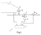
- Fig. 1 shows a schematic block diagram of a system 1 for monitoring the operability of a balise 2.
- the system comprises the balise 2 and a balise-related control unit 3.
- the balise-related control unit 3 and the balise 2 are connected by a cable 4.
- the system 1 comprises a central interlocking control unit 5 and a first track circuit 6a and another track circuit 6b.
- the track circuits 6a, 6b are arranged with a predetermined distance to each other along a track 8 at predetermined positions. It is shown that the balise 2 is arranged in between the track circuits 6a, 6b along a direction of travel.
- a rail vehicle 7 travels along the track 8.
- Rail vehicle 7 comprises an antenna 9 for transmitting a tele-powering signal 10.
- the tele-powering signal 10 is received by the balise 2.
- a telegram switch inhibit signal RS is generated by the balise 2 and transmitted to the balise-related control unit 3 via the cable 4.
- the balise-related control unit 3 generates data signals DS and transmits these data signals DS to the balise 2 which, in turn, transmits these data signals DS to the rail vehicle 7.
- a position of the rail vehicle 7 can be determined.
- the position of the track circuits 6a, 6b and the balise 2 is known.
- a vehicle passage of the balise 2 is detected.
- the corresponding time instant is determined and saved by the interlocking control unit 5. Also, time instants of the passage of the rail vehicle 7 of the first track circuit 6a and the second track circuit 6b are determined and saved.
- the detected time instant of the rail vehicle passage of the balise 2 is compared to a expected time interval, wherein limits of the time interval are provided by the time instants of the passages of the rail vehicle 7 of the first and the second track circuits 6a, 6b. If the expected time instant of the rail vehicle passage of the balise 2 lies within the time interval, a correct operation of the balise 2 can be detected.
- a correct operation can be detected, if the expected time instant of the rail vehicle passage of the balise 2 corresponds to the central time instant of the time interval or differs not more than a predetermined amount from said central time instant. In all other cases, an incorrect operability of the track sided transmitter 2 can be detected.
- the interlocking unit 5 can generate an alarm signal and, if applicable, activate a fail safe operation of selected or all other systems or devices controlled by the interlocking control unit 5.
Landscapes
- Engineering & Computer Science (AREA)
- Mechanical Engineering (AREA)
- Health & Medical Sciences (AREA)
- Biomedical Technology (AREA)
- General Health & Medical Sciences (AREA)
- Train Traffic Observation, Control, And Security (AREA)
- Electric Propulsion And Braking For Vehicles (AREA)
Priority Applications (3)
| Application Number | Priority Date | Filing Date | Title |
|---|---|---|---|
| PT131933004T PT2873585T (pt) | 2013-11-18 | 2013-11-18 | Método e sistema para monitorizar a operacionalidade de uma baliza |
| EP13193300.4A EP2873585B1 (de) | 2013-11-18 | 2013-11-18 | Verfahren und System zur Überwachung der Bedienbarkeit einer Balise |
| IN3203DE2014 IN2014DE03203A (de) | 2013-11-18 | 2014-11-05 |
Applications Claiming Priority (1)
| Application Number | Priority Date | Filing Date | Title |
|---|---|---|---|
| EP13193300.4A EP2873585B1 (de) | 2013-11-18 | 2013-11-18 | Verfahren und System zur Überwachung der Bedienbarkeit einer Balise |
Publications (2)
| Publication Number | Publication Date |
|---|---|
| EP2873585A1 true EP2873585A1 (de) | 2015-05-20 |
| EP2873585B1 EP2873585B1 (de) | 2016-05-25 |
Family
ID=49622685
Family Applications (1)
| Application Number | Title | Priority Date | Filing Date |
|---|---|---|---|
| EP13193300.4A Active EP2873585B1 (de) | 2013-11-18 | 2013-11-18 | Verfahren und System zur Überwachung der Bedienbarkeit einer Balise |
Country Status (3)
| Country | Link |
|---|---|
| EP (1) | EP2873585B1 (de) |
| IN (1) | IN2014DE03203A (de) |
| PT (1) | PT2873585T (de) |
Cited By (6)
| Publication number | Priority date | Publication date | Assignee | Title |
|---|---|---|---|---|
| BE1022851B1 (fr) * | 2015-03-20 | 2016-09-22 | Ertms Solutions | Vérification de l’état de fonctionnement d’une balise |
| WO2017008978A1 (de) * | 2015-07-10 | 2017-01-19 | Siemens Aktiengesellschaft | Streckenseitige eisenbahntechnische vorrichtung und verfahren zur erfassung einer benutzung wenigstens einer streckenseitigen komponente einer eisenbahnanlage |
| CN110779546A (zh) * | 2019-09-25 | 2020-02-11 | 交控科技股份有限公司 | 一种列车定位误差的校正方法和装置 |
| DE102019214637A1 (de) * | 2019-09-25 | 2021-03-25 | Siemens Mobility GmbH | Verfahren zum Überwachen von Funktionen einer Balise und hierfür geeignetes Lesegerät |
| DE102021110178A1 (de) | 2021-04-22 | 2022-10-27 | Scheidt & Bachmann Gmbh | Überwachungsvorrichtung für ein Schienensystem |
| EP4112418A1 (de) * | 2021-06-28 | 2023-01-04 | Bombardier Transportation GmbH | Vorrichtung und verfahren zur detektion von störenden metallobjekten an einem punkt einer eisenbahnstrecke |
Citations (2)
| Publication number | Priority date | Publication date | Assignee | Title |
|---|---|---|---|---|
| WO2007113128A1 (de) * | 2006-03-30 | 2007-10-11 | Siemens Aktiengesellschaft | Verfahren zum betreiben einer zugbeeinflussungseinrichtung und zugbeeinflussungseinrichtung |
| DE102009012986A1 (de) | 2009-03-12 | 2010-09-23 | Siemens Aktiengesellschaft | Verfahren zum Betreiben einer Zugbeeinflussungseinrichtung, streckenseitige elektonische Einheit und Balise für eine Zugbeeinflussungseinrichtung sowie Zugbeeinflussungseinrichtung |
-
2013
- 2013-11-18 EP EP13193300.4A patent/EP2873585B1/de active Active
- 2013-11-18 PT PT131933004T patent/PT2873585T/pt unknown
-
2014
- 2014-11-05 IN IN3203DE2014 patent/IN2014DE03203A/en unknown
Patent Citations (2)
| Publication number | Priority date | Publication date | Assignee | Title |
|---|---|---|---|---|
| WO2007113128A1 (de) * | 2006-03-30 | 2007-10-11 | Siemens Aktiengesellschaft | Verfahren zum betreiben einer zugbeeinflussungseinrichtung und zugbeeinflussungseinrichtung |
| DE102009012986A1 (de) | 2009-03-12 | 2010-09-23 | Siemens Aktiengesellschaft | Verfahren zum Betreiben einer Zugbeeinflussungseinrichtung, streckenseitige elektonische Einheit und Balise für eine Zugbeeinflussungseinrichtung sowie Zugbeeinflussungseinrichtung |
Non-Patent Citations (1)
| Title |
|---|
| "ERTMS/ETCS FFFIS for Eurobalise", 24 February 2012 (2012-02-24), pages 1 - 157, XP055112059, Retrieved from the Internet <URL:http://www.era.europa.eu/Document-Register/Documents/Set-2-Index009-SUBSET-036 v300.pdf> [retrieved on 20140403] * |
Cited By (8)
| Publication number | Priority date | Publication date | Assignee | Title |
|---|---|---|---|---|
| BE1022851B1 (fr) * | 2015-03-20 | 2016-09-22 | Ertms Solutions | Vérification de l’état de fonctionnement d’une balise |
| WO2017008978A1 (de) * | 2015-07-10 | 2017-01-19 | Siemens Aktiengesellschaft | Streckenseitige eisenbahntechnische vorrichtung und verfahren zur erfassung einer benutzung wenigstens einer streckenseitigen komponente einer eisenbahnanlage |
| US10457305B2 (en) | 2015-07-10 | 2019-10-29 | Siemens Aktiengesellschaft | Trackside railway apparatus and method for detecting use of at least one trackside component of a railway installation |
| CN110779546A (zh) * | 2019-09-25 | 2020-02-11 | 交控科技股份有限公司 | 一种列车定位误差的校正方法和装置 |
| DE102019214637A1 (de) * | 2019-09-25 | 2021-03-25 | Siemens Mobility GmbH | Verfahren zum Überwachen von Funktionen einer Balise und hierfür geeignetes Lesegerät |
| WO2021058220A1 (de) * | 2019-09-25 | 2021-04-01 | Siemens Mobility GmbH | Verfahren zum überwachen von funktionen einer balise und hierfür geeignetes lesegerät |
| DE102021110178A1 (de) | 2021-04-22 | 2022-10-27 | Scheidt & Bachmann Gmbh | Überwachungsvorrichtung für ein Schienensystem |
| EP4112418A1 (de) * | 2021-06-28 | 2023-01-04 | Bombardier Transportation GmbH | Vorrichtung und verfahren zur detektion von störenden metallobjekten an einem punkt einer eisenbahnstrecke |
Also Published As
| Publication number | Publication date |
|---|---|
| PT2873585T (pt) | 2016-08-16 |
| EP2873585B1 (de) | 2016-05-25 |
| IN2014DE03203A (de) | 2015-09-25 |
Similar Documents
| Publication | Publication Date | Title |
|---|---|---|
| US10081379B2 (en) | Broken rail detection system for communications-based train control | |
| EP2873585B1 (de) | Verfahren und System zur Überwachung der Bedienbarkeit einer Balise | |
| US8905360B2 (en) | Train signaling system and method for detecting distance-to-go of a train | |
| CN110730742B (zh) | 运行有轨交通系统的方法 | |
| AU2015224435B2 (en) | Device for confirming the integrity of a coupling of a rail vehicle and associated rail vehicle | |
| KR102211350B1 (ko) | 궤도회로 고장방지 장치 및 방법 | |
| KR101039769B1 (ko) | 철도신호 폐색 내 열차위치 정밀검지방법 | |
| KR101357806B1 (ko) | 열차 무결성 모니터링 시스템 | |
| US11325623B2 (en) | Rail breakage detection device and rail breakage detection system | |
| CN104334436B (zh) | 用于导轨元件的辅助操作的方法以及操作控制系统 | |
| US8469318B2 (en) | Device for the detection of the occupied or free state of a track section | |
| KR101210439B1 (ko) | 철도차량의 비상제동 제어장치 및 방법 | |
| EP3686079B1 (de) | Eisenbahngleisabschnitt mit zugdetektionssystem und zugehöriges verfahren zur detektion der präsenz eines schienenfahrzeuges auf einem gleisabschnitt | |
| EP3067246B1 (de) | Vorrichtung und Verfahren zur Überwachung der Funktionsfähigkeit einer Signalverbindung | |
| KR101798303B1 (ko) | 열차의 무선통신을 이용한 열차 무결성 모니터링 장치 | |
| JP2014111431A (ja) | 列車制御装置 | |
| US10527660B2 (en) | Method, controller and system for detecting a leakage of a track signal on at least one railway track | |
| AU2015100292A4 (en) | A device and a method for monitoring the operability of a signal connection | |
| KR101429258B1 (ko) | 철도 궤도를 이용한 휴대용 열차 접근 경보장치와 열차 접근 경보방법 | |
| KR101793310B1 (ko) | 철도 차량의 태그리더 고장 감지장치 | |
| JP2013075645A (ja) | 列車位置検知システム | |
| KR101378357B1 (ko) | 궤도 차량의 교차 검지장치 |
Legal Events
| Date | Code | Title | Description |
|---|---|---|---|
| PUAI | Public reference made under article 153(3) epc to a published international application that has entered the european phase |
Free format text: ORIGINAL CODE: 0009012 |
|
| 17P | Request for examination filed |
Effective date: 20141022 |
|
| AK | Designated contracting states |
Kind code of ref document: A1 Designated state(s): AL AT BE BG CH CY CZ DE DK EE ES FI FR GB GR HR HU IE IS IT LI LT LU LV MC MK MT NL NO PL PT RO RS SE SI SK SM TR |
|
| AX | Request for extension of the european patent |
Extension state: BA ME |
|
| GRAP | Despatch of communication of intention to grant a patent |
Free format text: ORIGINAL CODE: EPIDOSNIGR1 |
|
| RIC1 | Information provided on ipc code assigned before grant |
Ipc: B61L 3/12 20060101AFI20151221BHEP Ipc: B61L 27/00 20060101ALI20151221BHEP Ipc: B61L 25/02 20060101ALI20151221BHEP |
|
| INTG | Intention to grant announced |
Effective date: 20160121 |
|
| GRAS | Grant fee paid |
Free format text: ORIGINAL CODE: EPIDOSNIGR3 |
|
| GRAA | (expected) grant |
Free format text: ORIGINAL CODE: 0009210 |
|
| AK | Designated contracting states |
Kind code of ref document: B1 Designated state(s): AL AT BE BG CH CY CZ DE DK EE ES FI FR GB GR HR HU IE IS IT LI LT LU LV MC MK MT NL NO PL PT RO RS SE SI SK SM TR |
|
| REG | Reference to a national code |
Ref country code: GB Ref legal event code: FG4D |
|
| REG | Reference to a national code |
Ref country code: CH Ref legal event code: EP |
|
| REG | Reference to a national code |
Ref country code: IE Ref legal event code: FG4D Ref country code: AT Ref legal event code: REF Ref document number: 802036 Country of ref document: AT Kind code of ref document: T Effective date: 20160615 |
|
| REG | Reference to a national code |
Ref country code: DE Ref legal event code: R096 Ref document number: 602013007868 Country of ref document: DE |
|
| REG | Reference to a national code |
Ref country code: PT Ref legal event code: SC4A Ref document number: 2873585 Country of ref document: PT Date of ref document: 20160816 Kind code of ref document: T Free format text: AVAILABILITY OF NATIONAL TRANSLATION Effective date: 20160803 |
|
| REG | Reference to a national code |
Ref country code: SE Ref legal event code: TRGR |
|
| REG | Reference to a national code |
Ref country code: LT Ref legal event code: MG4D |
|
| REG | Reference to a national code |
Ref country code: NL Ref legal event code: MP Effective date: 20160525 |
|
| PG25 | Lapsed in a contracting state [announced via postgrant information from national office to epo] |
Ref country code: LT Free format text: LAPSE BECAUSE OF FAILURE TO SUBMIT A TRANSLATION OF THE DESCRIPTION OR TO PAY THE FEE WITHIN THE PRESCRIBED TIME-LIMIT Effective date: 20160525 Ref country code: FI Free format text: LAPSE BECAUSE OF FAILURE TO SUBMIT A TRANSLATION OF THE DESCRIPTION OR TO PAY THE FEE WITHIN THE PRESCRIBED TIME-LIMIT Effective date: 20160525 Ref country code: NO Free format text: LAPSE BECAUSE OF FAILURE TO SUBMIT A TRANSLATION OF THE DESCRIPTION OR TO PAY THE FEE WITHIN THE PRESCRIBED TIME-LIMIT Effective date: 20160825 Ref country code: NL Free format text: LAPSE BECAUSE OF FAILURE TO SUBMIT A TRANSLATION OF THE DESCRIPTION OR TO PAY THE FEE WITHIN THE PRESCRIBED TIME-LIMIT Effective date: 20160525 |
|
| REG | Reference to a national code |
Ref country code: AT Ref legal event code: MK05 Ref document number: 802036 Country of ref document: AT Kind code of ref document: T Effective date: 20160525 |
|
| REG | Reference to a national code |
Ref country code: FR Ref legal event code: PLFP Year of fee payment: 4 |
|
| PG25 | Lapsed in a contracting state [announced via postgrant information from national office to epo] |
Ref country code: GR Free format text: LAPSE BECAUSE OF FAILURE TO SUBMIT A TRANSLATION OF THE DESCRIPTION OR TO PAY THE FEE WITHIN THE PRESCRIBED TIME-LIMIT Effective date: 20160826 Ref country code: LV Free format text: LAPSE BECAUSE OF FAILURE TO SUBMIT A TRANSLATION OF THE DESCRIPTION OR TO PAY THE FEE WITHIN THE PRESCRIBED TIME-LIMIT Effective date: 20160525 Ref country code: RS Free format text: LAPSE BECAUSE OF FAILURE TO SUBMIT A TRANSLATION OF THE DESCRIPTION OR TO PAY THE FEE WITHIN THE PRESCRIBED TIME-LIMIT Effective date: 20160525 Ref country code: ES Free format text: LAPSE BECAUSE OF FAILURE TO SUBMIT A TRANSLATION OF THE DESCRIPTION OR TO PAY THE FEE WITHIN THE PRESCRIBED TIME-LIMIT Effective date: 20160525 |
|
| PG25 | Lapsed in a contracting state [announced via postgrant information from national office to epo] |
Ref country code: CZ Free format text: LAPSE BECAUSE OF FAILURE TO SUBMIT A TRANSLATION OF THE DESCRIPTION OR TO PAY THE FEE WITHIN THE PRESCRIBED TIME-LIMIT Effective date: 20160525 Ref country code: DK Free format text: LAPSE BECAUSE OF FAILURE TO SUBMIT A TRANSLATION OF THE DESCRIPTION OR TO PAY THE FEE WITHIN THE PRESCRIBED TIME-LIMIT Effective date: 20160525 Ref country code: RO Free format text: LAPSE BECAUSE OF FAILURE TO SUBMIT A TRANSLATION OF THE DESCRIPTION OR TO PAY THE FEE WITHIN THE PRESCRIBED TIME-LIMIT Effective date: 20160525 Ref country code: SK Free format text: LAPSE BECAUSE OF FAILURE TO SUBMIT A TRANSLATION OF THE DESCRIPTION OR TO PAY THE FEE WITHIN THE PRESCRIBED TIME-LIMIT Effective date: 20160525 Ref country code: EE Free format text: LAPSE BECAUSE OF FAILURE TO SUBMIT A TRANSLATION OF THE DESCRIPTION OR TO PAY THE FEE WITHIN THE PRESCRIBED TIME-LIMIT Effective date: 20160525 |
|
| PG25 | Lapsed in a contracting state [announced via postgrant information from national office to epo] |
Ref country code: BE Free format text: LAPSE BECAUSE OF FAILURE TO SUBMIT A TRANSLATION OF THE DESCRIPTION OR TO PAY THE FEE WITHIN THE PRESCRIBED TIME-LIMIT Effective date: 20160525 Ref country code: AT Free format text: LAPSE BECAUSE OF FAILURE TO SUBMIT A TRANSLATION OF THE DESCRIPTION OR TO PAY THE FEE WITHIN THE PRESCRIBED TIME-LIMIT Effective date: 20160525 Ref country code: PL Free format text: LAPSE BECAUSE OF FAILURE TO SUBMIT A TRANSLATION OF THE DESCRIPTION OR TO PAY THE FEE WITHIN THE PRESCRIBED TIME-LIMIT Effective date: 20160525 Ref country code: SM Free format text: LAPSE BECAUSE OF FAILURE TO SUBMIT A TRANSLATION OF THE DESCRIPTION OR TO PAY THE FEE WITHIN THE PRESCRIBED TIME-LIMIT Effective date: 20160525 |
|
| REG | Reference to a national code |
Ref country code: DE Ref legal event code: R097 Ref document number: 602013007868 Country of ref document: DE |
|
| PLBE | No opposition filed within time limit |
Free format text: ORIGINAL CODE: 0009261 |
|
| STAA | Information on the status of an ep patent application or granted ep patent |
Free format text: STATUS: NO OPPOSITION FILED WITHIN TIME LIMIT |
|
| 26N | No opposition filed |
Effective date: 20170228 |
|
| PG25 | Lapsed in a contracting state [announced via postgrant information from national office to epo] |
Ref country code: SI Free format text: LAPSE BECAUSE OF FAILURE TO SUBMIT A TRANSLATION OF THE DESCRIPTION OR TO PAY THE FEE WITHIN THE PRESCRIBED TIME-LIMIT Effective date: 20160525 |
|
| REG | Reference to a national code |
Ref country code: DE Ref legal event code: R119 Ref document number: 602013007868 Country of ref document: DE |
|
| REG | Reference to a national code |
Ref country code: CH Ref legal event code: PL |
|
| PG25 | Lapsed in a contracting state [announced via postgrant information from national office to epo] |
Ref country code: LI Free format text: LAPSE BECAUSE OF NON-PAYMENT OF DUE FEES Effective date: 20161130 Ref country code: CH Free format text: LAPSE BECAUSE OF NON-PAYMENT OF DUE FEES Effective date: 20161130 |
|
| REG | Reference to a national code |
Ref country code: IE Ref legal event code: MM4A |
|
| PG25 | Lapsed in a contracting state [announced via postgrant information from national office to epo] |
Ref country code: LU Free format text: LAPSE BECAUSE OF NON-PAYMENT OF DUE FEES Effective date: 20161130 |
|
| REG | Reference to a national code |
Ref country code: FR Ref legal event code: PLFP Year of fee payment: 5 |
|
| PG25 | Lapsed in a contracting state [announced via postgrant information from national office to epo] |
Ref country code: IE Free format text: LAPSE BECAUSE OF NON-PAYMENT OF DUE FEES Effective date: 20161118 Ref country code: DE Free format text: LAPSE BECAUSE OF NON-PAYMENT OF DUE FEES Effective date: 20170601 |
|
| PG25 | Lapsed in a contracting state [announced via postgrant information from national office to epo] |
Ref country code: HU Free format text: LAPSE BECAUSE OF FAILURE TO SUBMIT A TRANSLATION OF THE DESCRIPTION OR TO PAY THE FEE WITHIN THE PRESCRIBED TIME-LIMIT; INVALID AB INITIO Effective date: 20131118 |
|
| PG25 | Lapsed in a contracting state [announced via postgrant information from national office to epo] |
Ref country code: MC Free format text: LAPSE BECAUSE OF FAILURE TO SUBMIT A TRANSLATION OF THE DESCRIPTION OR TO PAY THE FEE WITHIN THE PRESCRIBED TIME-LIMIT Effective date: 20160525 Ref country code: IS Free format text: LAPSE BECAUSE OF FAILURE TO SUBMIT A TRANSLATION OF THE DESCRIPTION OR TO PAY THE FEE WITHIN THE PRESCRIBED TIME-LIMIT Effective date: 20160525 Ref country code: CY Free format text: LAPSE BECAUSE OF FAILURE TO SUBMIT A TRANSLATION OF THE DESCRIPTION OR TO PAY THE FEE WITHIN THE PRESCRIBED TIME-LIMIT Effective date: 20160525 Ref country code: MK Free format text: LAPSE BECAUSE OF FAILURE TO SUBMIT A TRANSLATION OF THE DESCRIPTION OR TO PAY THE FEE WITHIN THE PRESCRIBED TIME-LIMIT Effective date: 20160525 Ref country code: HR Free format text: LAPSE BECAUSE OF FAILURE TO SUBMIT A TRANSLATION OF THE DESCRIPTION OR TO PAY THE FEE WITHIN THE PRESCRIBED TIME-LIMIT Effective date: 20160525 |
|
| GBPC | Gb: european patent ceased through non-payment of renewal fee |
Effective date: 20171118 |
|
| PG25 | Lapsed in a contracting state [announced via postgrant information from national office to epo] |
Ref country code: BG Free format text: LAPSE BECAUSE OF FAILURE TO SUBMIT A TRANSLATION OF THE DESCRIPTION OR TO PAY THE FEE WITHIN THE PRESCRIBED TIME-LIMIT Effective date: 20160525 |
|
| PG25 | Lapsed in a contracting state [announced via postgrant information from national office to epo] |
Ref country code: MT Free format text: LAPSE BECAUSE OF NON-PAYMENT OF DUE FEES Effective date: 20161118 |
|
| PG25 | Lapsed in a contracting state [announced via postgrant information from national office to epo] |
Ref country code: TR Free format text: LAPSE BECAUSE OF FAILURE TO SUBMIT A TRANSLATION OF THE DESCRIPTION OR TO PAY THE FEE WITHIN THE PRESCRIBED TIME-LIMIT Effective date: 20160525 Ref country code: AL Free format text: LAPSE BECAUSE OF FAILURE TO SUBMIT A TRANSLATION OF THE DESCRIPTION OR TO PAY THE FEE WITHIN THE PRESCRIBED TIME-LIMIT Effective date: 20160525 |
|
| PG25 | Lapsed in a contracting state [announced via postgrant information from national office to epo] |
Ref country code: GB Free format text: LAPSE BECAUSE OF NON-PAYMENT OF DUE FEES Effective date: 20171118 |
|
| P01 | Opt-out of the competence of the unified patent court (upc) registered |
Effective date: 20230822 |
|
| PGFP | Annual fee paid to national office [announced via postgrant information from national office to epo] |
Ref country code: SE Payment date: 20231120 Year of fee payment: 11 Ref country code: PT Payment date: 20231109 Year of fee payment: 11 Ref country code: IT Payment date: 20231124 Year of fee payment: 11 Ref country code: FR Payment date: 20231120 Year of fee payment: 11 |