EP2872051B1 - Dispositif d'occlusion pour un appendice auriculaire - Google Patents
Dispositif d'occlusion pour un appendice auriculaire Download PDFInfo
- Publication number
- EP2872051B1 EP2872051B1 EP13740155.0A EP13740155A EP2872051B1 EP 2872051 B1 EP2872051 B1 EP 2872051B1 EP 13740155 A EP13740155 A EP 13740155A EP 2872051 B1 EP2872051 B1 EP 2872051B1
- Authority
- EP
- European Patent Office
- Prior art keywords
- struts
- distal
- strut ends
- proximal
- cage
- Prior art date
- Legal status (The legal status is an assumption and is not a legal conclusion. Google has not performed a legal analysis and makes no representation as to the accuracy of the status listed.)
- Active
Links
- 210000001008 atrial appendage Anatomy 0.000 title claims description 28
- 238000004519 manufacturing process Methods 0.000 claims description 14
- 238000005452 bending Methods 0.000 claims description 10
- 238000005520 cutting process Methods 0.000 claims description 10
- 239000000853 adhesive Substances 0.000 claims description 8
- 230000001070 adhesive effect Effects 0.000 claims description 8
- 238000003466 welding Methods 0.000 claims description 8
- 238000005476 soldering Methods 0.000 claims description 6
- 210000001316 polygonal cell Anatomy 0.000 claims description 5
- 238000000034 method Methods 0.000 description 28
- 239000012528 membrane Substances 0.000 description 27
- 239000000463 material Substances 0.000 description 26
- 239000003814 drug Substances 0.000 description 18
- 229940124597 therapeutic agent Drugs 0.000 description 12
- -1 Elgiloy and Phynox Chemical class 0.000 description 10
- 229910052751 metal Inorganic materials 0.000 description 10
- 239000002184 metal Substances 0.000 description 10
- 208000007536 Thrombosis Diseases 0.000 description 8
- 210000005248 left atrial appendage Anatomy 0.000 description 8
- 229920000642 polymer Polymers 0.000 description 8
- 229910045601 alloy Inorganic materials 0.000 description 7
- 239000000956 alloy Substances 0.000 description 7
- 230000017531 blood circulation Effects 0.000 description 7
- 239000003795 chemical substances by application Substances 0.000 description 7
- 230000002068 genetic effect Effects 0.000 description 7
- 229910001000 nickel titanium Inorganic materials 0.000 description 7
- YMWUJEATGCHHMB-UHFFFAOYSA-N Dichloromethane Chemical compound ClCCl YMWUJEATGCHHMB-UHFFFAOYSA-N 0.000 description 6
- ZMXDDKWLCZADIW-UHFFFAOYSA-N N,N-Dimethylformamide Chemical compound CN(C)C=O ZMXDDKWLCZADIW-UHFFFAOYSA-N 0.000 description 6
- 210000004027 cell Anatomy 0.000 description 6
- 150000001875 compounds Chemical class 0.000 description 6
- 229940079593 drug Drugs 0.000 description 6
- 150000002739 metals Chemical class 0.000 description 6
- 229920000728 polyester Polymers 0.000 description 6
- 102000004169 proteins and genes Human genes 0.000 description 6
- 108090000623 proteins and genes Proteins 0.000 description 6
- 239000008280 blood Substances 0.000 description 5
- 210000004369 blood Anatomy 0.000 description 5
- 238000000576 coating method Methods 0.000 description 5
- 210000002837 heart atrium Anatomy 0.000 description 5
- 238000002513 implantation Methods 0.000 description 5
- HLXZNVUGXRDIFK-UHFFFAOYSA-N nickel titanium Chemical compound [Ti].[Ti].[Ti].[Ti].[Ti].[Ti].[Ti].[Ti].[Ti].[Ti].[Ti].[Ni].[Ni].[Ni].[Ni].[Ni].[Ni].[Ni].[Ni].[Ni].[Ni].[Ni].[Ni].[Ni].[Ni] HLXZNVUGXRDIFK-UHFFFAOYSA-N 0.000 description 5
- 229920004934 Dacron® Polymers 0.000 description 4
- IAZDPXIOMUYVGZ-UHFFFAOYSA-N Dimethylsulphoxide Chemical compound CS(C)=O IAZDPXIOMUYVGZ-UHFFFAOYSA-N 0.000 description 4
- HTTJABKRGRZYRN-UHFFFAOYSA-N Heparin Chemical compound OC1C(NC(=O)C)C(O)OC(COS(O)(=O)=O)C1OC1C(OS(O)(=O)=O)C(O)C(OC2C(C(OS(O)(=O)=O)C(OC3C(C(O)C(O)C(O3)C(O)=O)OS(O)(=O)=O)C(CO)O2)NS(O)(=O)=O)C(C(O)=O)O1 HTTJABKRGRZYRN-UHFFFAOYSA-N 0.000 description 4
- 229920000954 Polyglycolide Polymers 0.000 description 4
- 208000006011 Stroke Diseases 0.000 description 4
- WYURNTSHIVDZCO-UHFFFAOYSA-N Tetrahydrofuran Chemical compound C1CCOC1 WYURNTSHIVDZCO-UHFFFAOYSA-N 0.000 description 4
- UYXTWWCETRIEDR-UHFFFAOYSA-N Tributyrin Chemical compound CCCC(=O)OCC(OC(=O)CCC)COC(=O)CCC UYXTWWCETRIEDR-UHFFFAOYSA-N 0.000 description 4
- 239000003146 anticoagulant agent Substances 0.000 description 4
- 229940127219 anticoagulant drug Drugs 0.000 description 4
- 239000000560 biocompatible material Substances 0.000 description 4
- 238000003698 laser cutting Methods 0.000 description 4
- 239000000203 mixture Substances 0.000 description 4
- 239000000546 pharmaceutical excipient Substances 0.000 description 4
- BASFCYQUMIYNBI-UHFFFAOYSA-N platinum Chemical compound [Pt] BASFCYQUMIYNBI-UHFFFAOYSA-N 0.000 description 4
- 239000004633 polyglycolic acid Substances 0.000 description 4
- 229920001343 polytetrafluoroethylene Polymers 0.000 description 4
- 239000004810 polytetrafluoroethylene Substances 0.000 description 4
- 239000000126 substance Substances 0.000 description 4
- 210000005166 vasculature Anatomy 0.000 description 4
- CSCPPACGZOOCGX-UHFFFAOYSA-N Acetone Chemical compound CC(C)=O CSCPPACGZOOCGX-UHFFFAOYSA-N 0.000 description 3
- WEVYAHXRMPXWCK-UHFFFAOYSA-N Acetonitrile Chemical compound CC#N WEVYAHXRMPXWCK-UHFFFAOYSA-N 0.000 description 3
- 206010003658 Atrial Fibrillation Diseases 0.000 description 3
- XEKOWRVHYACXOJ-UHFFFAOYSA-N Ethyl acetate Chemical compound CCOC(C)=O XEKOWRVHYACXOJ-UHFFFAOYSA-N 0.000 description 3
- 230000001028 anti-proliverative effect Effects 0.000 description 3
- 230000001413 cellular effect Effects 0.000 description 3
- 229920001577 copolymer Polymers 0.000 description 3
- 229960002897 heparin Drugs 0.000 description 3
- 229920000669 heparin Polymers 0.000 description 3
- JJTUDXZGHPGLLC-UHFFFAOYSA-N lactide Chemical compound CC1OC(=O)C(C)OC1=O JJTUDXZGHPGLLC-UHFFFAOYSA-N 0.000 description 3
- 229920000747 poly(lactic acid) Polymers 0.000 description 3
- 229920001610 polycaprolactone Polymers 0.000 description 3
- 239000004632 polycaprolactone Substances 0.000 description 3
- 229920001296 polysiloxane Polymers 0.000 description 3
- QZCLKYGREBVARF-UHFFFAOYSA-N Acetyl tributyl citrate Chemical compound CCCCOC(=O)CC(C(=O)OCCCC)(OC(C)=O)CC(=O)OCCCC QZCLKYGREBVARF-UHFFFAOYSA-N 0.000 description 2
- DKPFZGUDAPQIHT-UHFFFAOYSA-N Butyl acetate Natural products CCCCOC(C)=O DKPFZGUDAPQIHT-UHFFFAOYSA-N 0.000 description 2
- 108010035532 Collagen Proteins 0.000 description 2
- 102000008186 Collagen Human genes 0.000 description 2
- JOYRKODLDBILNP-UHFFFAOYSA-N Ethyl urethane Chemical compound CCOC(N)=O JOYRKODLDBILNP-UHFFFAOYSA-N 0.000 description 2
- 229920000544 Gore-Tex Polymers 0.000 description 2
- JVTAAEKCZFNVCJ-UHFFFAOYSA-M Lactate Chemical compound CC(O)C([O-])=O JVTAAEKCZFNVCJ-UHFFFAOYSA-M 0.000 description 2
- 229930012538 Paclitaxel Natural products 0.000 description 2
- 229910001260 Pt alloy Inorganic materials 0.000 description 2
- 229910000639 Spring steel Inorganic materials 0.000 description 2
- 229920006362 Teflon® Polymers 0.000 description 2
- RTAQQCXQSZGOHL-UHFFFAOYSA-N Titanium Chemical compound [Ti] RTAQQCXQSZGOHL-UHFFFAOYSA-N 0.000 description 2
- JXLYSJRDGCGARV-WWYNWVTFSA-N Vinblastine Natural products O=C(O[C@H]1[C@](O)(C(=O)OC)[C@@H]2N(C)c3c(cc(c(OC)c3)[C@]3(C(=O)OC)c4[nH]c5c(c4CCN4C[C@](O)(CC)C[C@H](C3)C4)cccc5)[C@@]32[C@H]2[C@@]1(CC)C=CCN2CC3)C JXLYSJRDGCGARV-WWYNWVTFSA-N 0.000 description 2
- HZEWFHLRYVTOIW-UHFFFAOYSA-N [Ti].[Ni] Chemical compound [Ti].[Ni] HZEWFHLRYVTOIW-UHFFFAOYSA-N 0.000 description 2
- KGXDGSMJNUPTEQ-UHFFFAOYSA-N [Ti].[Ni].[Pt] Chemical compound [Ti].[Ni].[Pt] KGXDGSMJNUPTEQ-UHFFFAOYSA-N 0.000 description 2
- 239000002253 acid Substances 0.000 description 2
- 239000013543 active substance Substances 0.000 description 2
- 238000004873 anchoring Methods 0.000 description 2
- 230000000118 anti-neoplastic effect Effects 0.000 description 2
- 230000002965 anti-thrombogenic effect Effects 0.000 description 2
- 229920000249 biocompatible polymer Polymers 0.000 description 2
- 229920002988 biodegradable polymer Polymers 0.000 description 2
- 239000004621 biodegradable polymer Substances 0.000 description 2
- 230000031018 biological processes and functions Effects 0.000 description 2
- 230000015572 biosynthetic process Effects 0.000 description 2
- 230000015556 catabolic process Effects 0.000 description 2
- 239000000788 chromium alloy Substances 0.000 description 2
- 229920001436 collagen Polymers 0.000 description 2
- 239000002131 composite material Substances 0.000 description 2
- 238000000354 decomposition reaction Methods 0.000 description 2
- 230000007547 defect Effects 0.000 description 2
- 239000013013 elastic material Substances 0.000 description 2
- 229910000701 elgiloys (Co-Cr-Ni Alloy) Inorganic materials 0.000 description 2
- 239000000835 fiber Substances 0.000 description 2
- 239000012530 fluid Substances 0.000 description 2
- PCHJSUWPFVWCPO-UHFFFAOYSA-N gold Chemical compound [Au] PCHJSUWPFVWCPO-UHFFFAOYSA-N 0.000 description 2
- 229910052737 gold Inorganic materials 0.000 description 2
- 239000010931 gold Substances 0.000 description 2
- FUZZWVXGSFPDMH-UHFFFAOYSA-N hexanoic acid Chemical compound CCCCCC(O)=O FUZZWVXGSFPDMH-UHFFFAOYSA-N 0.000 description 2
- 229920001903 high density polyethylene Polymers 0.000 description 2
- 239000004700 high-density polyethylene Substances 0.000 description 2
- 229920001477 hydrophilic polymer Polymers 0.000 description 2
- 210000005246 left atrium Anatomy 0.000 description 2
- 230000007774 longterm Effects 0.000 description 2
- 229960001592 paclitaxel Drugs 0.000 description 2
- 229910052697 platinum Inorganic materials 0.000 description 2
- HWLDNSXPUQTBOD-UHFFFAOYSA-N platinum-iridium alloy Chemical class [Ir].[Pt] HWLDNSXPUQTBOD-UHFFFAOYSA-N 0.000 description 2
- 229920000515 polycarbonate Polymers 0.000 description 2
- 239000004417 polycarbonate Substances 0.000 description 2
- 239000004626 polylactic acid Substances 0.000 description 2
- ZAHRKKWIAAJSAO-UHFFFAOYSA-N rapamycin Natural products COCC(O)C(=C/C(C)C(=O)CC(OC(=O)C1CCCCN1C(=O)C(=O)C2(O)OC(CC(OC)C(=CC=CC=CC(C)CC(C)C(=O)C)C)CCC2C)C(C)CC3CCC(O)C(C3)OC)C ZAHRKKWIAAJSAO-UHFFFAOYSA-N 0.000 description 2
- 238000005096 rolling process Methods 0.000 description 2
- 239000012781 shape memory material Substances 0.000 description 2
- 229960002930 sirolimus Drugs 0.000 description 2
- QFJCIRLUMZQUOT-HPLJOQBZSA-N sirolimus Chemical compound C1C[C@@H](O)[C@H](OC)C[C@@H]1C[C@@H](C)[C@H]1OC(=O)[C@@H]2CCCCN2C(=O)C(=O)[C@](O)(O2)[C@H](C)CC[C@H]2C[C@H](OC)/C(C)=C/C=C/C=C/[C@@H](C)C[C@@H](C)C(=O)[C@H](OC)[C@H](O)/C(C)=C/[C@@H](C)C(=O)C1 QFJCIRLUMZQUOT-HPLJOQBZSA-N 0.000 description 2
- 239000002904 solvent Substances 0.000 description 2
- 229910001220 stainless steel Inorganic materials 0.000 description 2
- 239000010935 stainless steel Substances 0.000 description 2
- 229910052715 tantalum Inorganic materials 0.000 description 2
- GUVRBAGPIYLISA-UHFFFAOYSA-N tantalum atom Chemical compound [Ta] GUVRBAGPIYLISA-UHFFFAOYSA-N 0.000 description 2
- RCINICONZNJXQF-MZXODVADSA-N taxol Chemical compound O([C@@H]1[C@@]2(C[C@@H](C(C)=C(C2(C)C)[C@H](C([C@]2(C)[C@@H](O)C[C@H]3OC[C@]3([C@H]21)OC(C)=O)=O)OC(=O)C)OC(=O)[C@H](O)[C@@H](NC(=O)C=1C=CC=CC=1)C=1C=CC=CC=1)O)C(=O)C1=CC=CC=C1 RCINICONZNJXQF-MZXODVADSA-N 0.000 description 2
- YLQBMQCUIZJEEH-UHFFFAOYSA-N tetrahydrofuran Natural products C=1C=COC=1 YLQBMQCUIZJEEH-UHFFFAOYSA-N 0.000 description 2
- 230000001225 therapeutic effect Effects 0.000 description 2
- 229910052719 titanium Inorganic materials 0.000 description 2
- 239000010936 titanium Substances 0.000 description 2
- 230000007704 transition Effects 0.000 description 2
- WEAPVABOECTMGR-UHFFFAOYSA-N triethyl 2-acetyloxypropane-1,2,3-tricarboxylate Chemical compound CCOC(=O)CC(C(=O)OCC)(OC(C)=O)CC(=O)OCC WEAPVABOECTMGR-UHFFFAOYSA-N 0.000 description 2
- WFKWXMTUELFFGS-UHFFFAOYSA-N tungsten Chemical compound [W] WFKWXMTUELFFGS-UHFFFAOYSA-N 0.000 description 2
- 239000010937 tungsten Substances 0.000 description 2
- 229910052721 tungsten Inorganic materials 0.000 description 2
- 229960003048 vinblastine Drugs 0.000 description 2
- JXLYSJRDGCGARV-XQKSVPLYSA-N vincaleukoblastine Chemical compound C([C@@H](C[C@]1(C(=O)OC)C=2C(=CC3=C([C@]45[C@H]([C@@]([C@H](OC(C)=O)[C@]6(CC)C=CCN([C@H]56)CC4)(O)C(=O)OC)N3C)C=2)OC)C[C@@](C2)(O)CC)N2CCC2=C1NC1=CC=CC=C21 JXLYSJRDGCGARV-XQKSVPLYSA-N 0.000 description 2
- 229960004528 vincristine Drugs 0.000 description 2
- OGWKCGZFUXNPDA-XQKSVPLYSA-N vincristine Chemical compound C([N@]1C[C@@H](C[C@]2(C(=O)OC)C=3C(=CC4=C([C@]56[C@H]([C@@]([C@H](OC(C)=O)[C@]7(CC)C=CCN([C@H]67)CC5)(O)C(=O)OC)N4C=O)C=3)OC)C[C@@](C1)(O)CC)CC1=C2NC2=CC=CC=C12 OGWKCGZFUXNPDA-XQKSVPLYSA-N 0.000 description 2
- OGWKCGZFUXNPDA-UHFFFAOYSA-N vincristine Natural products C1C(CC)(O)CC(CC2(C(=O)OC)C=3C(=CC4=C(C56C(C(C(OC(C)=O)C7(CC)C=CCN(C67)CC5)(O)C(=O)OC)N4C=O)C=3)OC)CN1CCC1=C2NC2=CC=CC=C12 OGWKCGZFUXNPDA-UHFFFAOYSA-N 0.000 description 2
- BLTXWCKMNMYXEA-UHFFFAOYSA-N 1,1,2-trifluoro-2-(trifluoromethoxy)ethene Chemical compound FC(F)=C(F)OC(F)(F)F BLTXWCKMNMYXEA-UHFFFAOYSA-N 0.000 description 1
- BZPCMSSQHRAJCC-UHFFFAOYSA-N 1,2,3,3,4,4,5,5,5-nonafluoro-1-(1,2,3,3,4,4,5,5,5-nonafluoropent-1-enoxy)pent-1-ene Chemical compound FC(F)(F)C(F)(F)C(F)(F)C(F)=C(F)OC(F)=C(F)C(F)(F)C(F)(F)C(F)(F)F BZPCMSSQHRAJCC-UHFFFAOYSA-N 0.000 description 1
- RKDVKSZUMVYZHH-UHFFFAOYSA-N 1,4-dioxane-2,5-dione Chemical compound O=C1COC(=O)CO1 RKDVKSZUMVYZHH-UHFFFAOYSA-N 0.000 description 1
- LTMRRSWNXVJMBA-UHFFFAOYSA-L 2,2-diethylpropanedioate Chemical compound CCC(CC)(C([O-])=O)C([O-])=O LTMRRSWNXVJMBA-UHFFFAOYSA-L 0.000 description 1
- QBBTZXBTFYKMKT-UHFFFAOYSA-N 2,3-diacetyloxypropyl acetate Chemical compound CC(=O)OCC(OC(C)=O)COC(C)=O.CC(=O)OCC(OC(C)=O)COC(C)=O QBBTZXBTFYKMKT-UHFFFAOYSA-N 0.000 description 1
- AGNTUZCMJBTHOG-UHFFFAOYSA-N 3-[3-(2,3-dihydroxypropoxy)-2-hydroxypropoxy]propane-1,2-diol Chemical compound OCC(O)COCC(O)COCC(O)CO AGNTUZCMJBTHOG-UHFFFAOYSA-N 0.000 description 1
- LPEKGGXMPWTOCB-UHFFFAOYSA-N 8beta-(2,3-epoxy-2-methylbutyryloxy)-14-acetoxytithifolin Natural products COC(=O)C(C)O LPEKGGXMPWTOCB-UHFFFAOYSA-N 0.000 description 1
- 102400000068 Angiostatin Human genes 0.000 description 1
- 108010079709 Angiostatins Proteins 0.000 description 1
- REIYHFWZISXFKU-UHFFFAOYSA-N Butyl acetoacetate Chemical compound CCCCOC(=O)CC(C)=O REIYHFWZISXFKU-UHFFFAOYSA-N 0.000 description 1
- MRABAEUHTLLEML-UHFFFAOYSA-N Butyl lactate Chemical compound CCCCOC(=O)C(C)O MRABAEUHTLLEML-UHFFFAOYSA-N 0.000 description 1
- FEWJPZIEWOKRBE-JCYAYHJZSA-N Dextrotartaric acid Chemical compound OC(=O)[C@H](O)[C@@H](O)C(O)=O FEWJPZIEWOKRBE-JCYAYHJZSA-N 0.000 description 1
- IEPRKVQEAMIZSS-UHFFFAOYSA-N Di-Et ester-Fumaric acid Natural products CCOC(=O)C=CC(=O)OCC IEPRKVQEAMIZSS-UHFFFAOYSA-N 0.000 description 1
- OIFBSDVPJOWBCH-UHFFFAOYSA-N Diethyl carbonate Chemical compound CCOC(=O)OCC OIFBSDVPJOWBCH-UHFFFAOYSA-N 0.000 description 1
- IEPRKVQEAMIZSS-WAYWQWQTSA-N Diethyl maleate Chemical compound CCOC(=O)\C=C/C(=O)OCC IEPRKVQEAMIZSS-WAYWQWQTSA-N 0.000 description 1
- DKMROQRQHGEIOW-UHFFFAOYSA-N Diethyl succinate Chemical compound CCOC(=O)CCC(=O)OCC DKMROQRQHGEIOW-UHFFFAOYSA-N 0.000 description 1
- YSAVZVORKRDODB-UHFFFAOYSA-N Diethyl tartrate Chemical compound CCOC(=O)C(O)C(O)C(=O)OCC YSAVZVORKRDODB-UHFFFAOYSA-N 0.000 description 1
- MWWSFMDVAYGXBV-RUELKSSGSA-N Doxorubicin hydrochloride Chemical compound Cl.O([C@H]1C[C@@](O)(CC=2C(O)=C3C(=O)C=4C=CC=C(C=4C(=O)C3=C(O)C=21)OC)C(=O)CO)[C@H]1C[C@H](N)[C@H](O)[C@H](C)O1 MWWSFMDVAYGXBV-RUELKSSGSA-N 0.000 description 1
- 208000005189 Embolism Diseases 0.000 description 1
- 102400001047 Endostatin Human genes 0.000 description 1
- 108010079505 Endostatins Proteins 0.000 description 1
- KMTRUDSVKNLOMY-UHFFFAOYSA-N Ethylene carbonate Chemical compound O=C1OCCO1 KMTRUDSVKNLOMY-UHFFFAOYSA-N 0.000 description 1
- GHASVSINZRGABV-UHFFFAOYSA-N Fluorouracil Chemical compound FC1=CNC(=O)NC1=O GHASVSINZRGABV-UHFFFAOYSA-N 0.000 description 1
- 102000003693 Hedgehog Proteins Human genes 0.000 description 1
- 108090000031 Hedgehog Proteins Proteins 0.000 description 1
- FBOZXECLQNJBKD-ZDUSSCGKSA-N L-methotrexate Chemical compound C=1N=C2N=C(N)N=C(N)C2=NC=1CN(C)C1=CC=C(C(=O)N[C@@H](CCC(O)=O)C(O)=O)C=C1 FBOZXECLQNJBKD-ZDUSSCGKSA-N 0.000 description 1
- WRQNANDWMGAFTP-UHFFFAOYSA-N Methylacetoacetic acid Chemical compound COC(=O)CC(C)=O WRQNANDWMGAFTP-UHFFFAOYSA-N 0.000 description 1
- 229920001410 Microfiber Polymers 0.000 description 1
- 229930192392 Mitomycin Natural products 0.000 description 1
- NWIBSHFKIJFRCO-WUDYKRTCSA-N Mytomycin Chemical compound C1N2C(C(C(C)=C(N)C3=O)=O)=C3[C@@H](COC(N)=O)[C@@]2(OC)[C@@H]2[C@H]1N2 NWIBSHFKIJFRCO-WUDYKRTCSA-N 0.000 description 1
- 229920003171 Poly (ethylene oxide) Polymers 0.000 description 1
- 239000004793 Polystyrene Substances 0.000 description 1
- ZIJKGAXBCRWEOL-SAXBRCJISA-N Sucrose octaacetate Chemical compound CC(=O)O[C@H]1[C@H](OC(C)=O)[C@@H](COC(=O)C)O[C@@]1(COC(C)=O)O[C@@H]1[C@H](OC(C)=O)[C@@H](OC(C)=O)[C@H](OC(C)=O)[C@@H](COC(C)=O)O1 ZIJKGAXBCRWEOL-SAXBRCJISA-N 0.000 description 1
- QJJXYPPXXYFBGM-LFZNUXCKSA-N Tacrolimus Chemical compound C1C[C@@H](O)[C@H](OC)C[C@@H]1\C=C(/C)[C@@H]1[C@H](C)[C@@H](O)CC(=O)[C@H](CC=C)/C=C(C)/C[C@H](C)C[C@H](OC)[C@H]([C@H](C[C@H]2C)OC)O[C@@]2(O)C(=O)C(=O)N2CCCC[C@H]2C(=O)O1 QJJXYPPXXYFBGM-LFZNUXCKSA-N 0.000 description 1
- 239000001083 [(2R,3R,4S,5R)-1,2,4,5-tetraacetyloxy-6-oxohexan-3-yl] acetate Substances 0.000 description 1
- 239000001344 [(2S,3S,4R,5R)-4-acetyloxy-2,5-bis(acetyloxymethyl)-2-[(2R,3R,4S,5R,6R)-3,4,5-triacetyloxy-6-(acetyloxymethyl)oxan-2-yl]oxyoxolan-3-yl] acetate Substances 0.000 description 1
- UAOKXEHOENRFMP-ZJIFWQFVSA-N [(2r,3r,4s,5r)-2,3,4,5-tetraacetyloxy-6-oxohexyl] acetate Chemical compound CC(=O)OC[C@@H](OC(C)=O)[C@@H](OC(C)=O)[C@H](OC(C)=O)[C@@H](OC(C)=O)C=O UAOKXEHOENRFMP-ZJIFWQFVSA-N 0.000 description 1
- 238000002679 ablation Methods 0.000 description 1
- 239000011149 active material Substances 0.000 description 1
- 229920000615 alginic acid Polymers 0.000 description 1
- 235000010443 alginic acid Nutrition 0.000 description 1
- 230000003266 anti-allergic effect Effects 0.000 description 1
- 230000003110 anti-inflammatory effect Effects 0.000 description 1
- 230000002927 anti-mitotic effect Effects 0.000 description 1
- 230000000702 anti-platelet effect Effects 0.000 description 1
- 239000003080 antimitotic agent Substances 0.000 description 1
- 239000003963 antioxidant agent Substances 0.000 description 1
- 230000003078 antioxidant effect Effects 0.000 description 1
- 210000001765 aortic valve Anatomy 0.000 description 1
- FZCSTZYAHCUGEM-UHFFFAOYSA-N aspergillomarasmine B Natural products OC(=O)CNC(C(O)=O)CNC(C(O)=O)CC(O)=O FZCSTZYAHCUGEM-UHFFFAOYSA-N 0.000 description 1
- 230000001746 atrial effect Effects 0.000 description 1
- 230000009286 beneficial effect Effects 0.000 description 1
- 239000012867 bioactive agent Substances 0.000 description 1
- 230000003115 biocidal effect Effects 0.000 description 1
- 229920001400 block copolymer Polymers 0.000 description 1
- 210000004556 brain Anatomy 0.000 description 1
- 239000001191 butyl (2R)-2-hydroxypropanoate Substances 0.000 description 1
- VFGRALUHHHDIQI-UHFFFAOYSA-N butyl 2-hydroxyacetate Chemical compound CCCCOC(=O)CO VFGRALUHHHDIQI-UHFFFAOYSA-N 0.000 description 1
- 150000001720 carbohydrates Chemical class 0.000 description 1
- 230000000747 cardiac effect Effects 0.000 description 1
- 230000010261 cell growth Effects 0.000 description 1
- 230000002490 cerebral effect Effects 0.000 description 1
- 230000004087 circulation Effects 0.000 description 1
- DQLATGHUWYMOKM-UHFFFAOYSA-L cisplatin Chemical compound N[Pt](N)(Cl)Cl DQLATGHUWYMOKM-UHFFFAOYSA-L 0.000 description 1
- 229960004316 cisplatin Drugs 0.000 description 1
- 230000035602 clotting Effects 0.000 description 1
- 239000011248 coating agent Substances 0.000 description 1
- 239000008199 coating composition Substances 0.000 description 1
- 239000006184 cosolvent Substances 0.000 description 1
- 229940072645 coumadin Drugs 0.000 description 1
- 238000002788 crimping Methods 0.000 description 1
- OLLQYIBTJXUEEX-UHFFFAOYSA-N diethyl 3-hydroxypentanedioate Chemical compound CCOC(=O)CC(O)CC(=O)OCC OLLQYIBTJXUEEX-UHFFFAOYSA-N 0.000 description 1
- OUWSNHWQZPEFEX-UHFFFAOYSA-N diethyl glutarate Chemical compound CCOC(=O)CCCC(=O)OCC OUWSNHWQZPEFEX-UHFFFAOYSA-N 0.000 description 1
- 125000004177 diethyl group Chemical group [H]C([H])([H])C([H])([H])* 0.000 description 1
- XTDYIOOONNVFMA-UHFFFAOYSA-N dimethyl pentanedioate Chemical compound COC(=O)CCCC(=O)OC XTDYIOOONNVFMA-UHFFFAOYSA-N 0.000 description 1
- ODQWQRRAPPTVAG-GZTJUZNOSA-N doxepin Chemical compound C1OC2=CC=CC=C2C(=C/CCN(C)C)/C2=CC=CC=C21 ODQWQRRAPPTVAG-GZTJUZNOSA-N 0.000 description 1
- 229960002918 doxorubicin hydrochloride Drugs 0.000 description 1
- 238000002651 drug therapy Methods 0.000 description 1
- 229930013356 epothilone Natural products 0.000 description 1
- HESCAJZNRMSMJG-KKQRBIROSA-N epothilone A Chemical class C/C([C@@H]1C[C@@H]2O[C@@H]2CCC[C@@H]([C@@H]([C@@H](C)C(=O)C(C)(C)[C@@H](O)CC(=O)O1)O)C)=C\C1=CSC(C)=N1 HESCAJZNRMSMJG-KKQRBIROSA-N 0.000 description 1
- ZANNOFHADGWOLI-UHFFFAOYSA-N ethyl 2-hydroxyacetate Chemical compound CCOC(=O)CO ZANNOFHADGWOLI-UHFFFAOYSA-N 0.000 description 1
- XYIBRDXRRQCHLP-UHFFFAOYSA-N ethyl acetoacetate Chemical compound CCOC(=O)CC(C)=O XYIBRDXRRQCHLP-UHFFFAOYSA-N 0.000 description 1
- 229960005167 everolimus Drugs 0.000 description 1
- 239000003527 fibrinolytic agent Substances 0.000 description 1
- 238000001914 filtration Methods 0.000 description 1
- 229960002949 fluorouracil Drugs 0.000 description 1
- 229940050410 gluconate Drugs 0.000 description 1
- 239000003102 growth factor Substances 0.000 description 1
- 239000007952 growth promoter Substances 0.000 description 1
- 208000019622 heart disease Diseases 0.000 description 1
- 239000002628 heparin derivative Substances 0.000 description 1
- 239000000017 hydrogel Substances 0.000 description 1
- 125000002768 hydroxyalkyl group Chemical group 0.000 description 1
- 238000011065 in-situ storage Methods 0.000 description 1
- 239000003112 inhibitor Substances 0.000 description 1
- 238000010329 laser etching Methods 0.000 description 1
- 238000003754 machining Methods 0.000 description 1
- 239000011159 matrix material Substances 0.000 description 1
- 229960000485 methotrexate Drugs 0.000 description 1
- 229940057867 methyl lactate Drugs 0.000 description 1
- 239000003658 microfiber Substances 0.000 description 1
- 229960004857 mitomycin Drugs 0.000 description 1
- 238000012986 modification Methods 0.000 description 1
- 230000004048 modification Effects 0.000 description 1
- 210000000056 organ Anatomy 0.000 description 1
- 239000000825 pharmaceutical preparation Substances 0.000 description 1
- 229940127557 pharmaceutical product Drugs 0.000 description 1
- 229920003023 plastic Polymers 0.000 description 1
- 239000004033 plastic Substances 0.000 description 1
- 229920000412 polyarylene Polymers 0.000 description 1
- 239000002861 polymer material Substances 0.000 description 1
- 229920002223 polystyrene Polymers 0.000 description 1
- 229920002451 polyvinyl alcohol Polymers 0.000 description 1
- 235000019422 polyvinyl alcohol Nutrition 0.000 description 1
- 238000007493 shaping process Methods 0.000 description 1
- 229920002379 silicone rubber Polymers 0.000 description 1
- 239000004945 silicone rubber Substances 0.000 description 1
- 229920006132 styrene block copolymer Polymers 0.000 description 1
- 229940013883 sucrose octaacetate Drugs 0.000 description 1
- 238000001356 surgical procedure Methods 0.000 description 1
- 229960001967 tacrolimus Drugs 0.000 description 1
- QJJXYPPXXYFBGM-SHYZHZOCSA-N tacrolimus Natural products CO[C@H]1C[C@H](CC[C@@H]1O)C=C(C)[C@H]2OC(=O)[C@H]3CCCCN3C(=O)C(=O)[C@@]4(O)O[C@@H]([C@H](C[C@H]4C)OC)[C@@H](C[C@H](C)CC(=C[C@@H](CC=C)C(=O)C[C@H](O)[C@H]2C)C)OC QJJXYPPXXYFBGM-SHYZHZOCSA-N 0.000 description 1
- BFKJFAAPBSQJPD-UHFFFAOYSA-N tetrafluoroethene Chemical group FC(F)=C(F)F BFKJFAAPBSQJPD-UHFFFAOYSA-N 0.000 description 1
- 239000003803 thymidine kinase inhibitor Substances 0.000 description 1
- 229920000428 triblock copolymer Polymers 0.000 description 1
- VLPFTAMPNXLGLX-UHFFFAOYSA-N trioctanoin Chemical compound CCCCCCCC(=O)OCC(OC(=O)CCCCCCC)COC(=O)CCCCCCC VLPFTAMPNXLGLX-UHFFFAOYSA-N 0.000 description 1
- 210000005167 vascular cell Anatomy 0.000 description 1
- PJVWKTKQMONHTI-UHFFFAOYSA-N warfarin Chemical compound OC=1C2=CC=CC=C2OC(=O)C=1C(CC(=O)C)C1=CC=CC=C1 PJVWKTKQMONHTI-UHFFFAOYSA-N 0.000 description 1
- XLYOFNOQVPJJNP-UHFFFAOYSA-N water Substances O XLYOFNOQVPJJNP-UHFFFAOYSA-N 0.000 description 1
- 229950009819 zotarolimus Drugs 0.000 description 1
Images


Classifications
-
- A—HUMAN NECESSITIES
- A61—MEDICAL OR VETERINARY SCIENCE; HYGIENE
- A61B—DIAGNOSIS; SURGERY; IDENTIFICATION
- A61B17/00—Surgical instruments, devices or methods, e.g. tourniquets
- A61B17/12—Surgical instruments, devices or methods, e.g. tourniquets for ligaturing or otherwise compressing tubular parts of the body, e.g. blood vessels, umbilical cord
- A61B17/12022—Occluding by internal devices, e.g. balloons or releasable wires
- A61B17/12099—Occluding by internal devices, e.g. balloons or releasable wires characterised by the location of the occluder
- A61B17/12122—Occluding by internal devices, e.g. balloons or releasable wires characterised by the location of the occluder within the heart
-
- A—HUMAN NECESSITIES
- A61—MEDICAL OR VETERINARY SCIENCE; HYGIENE
- A61B—DIAGNOSIS; SURGERY; IDENTIFICATION
- A61B17/00—Surgical instruments, devices or methods, e.g. tourniquets
- A61B17/12—Surgical instruments, devices or methods, e.g. tourniquets for ligaturing or otherwise compressing tubular parts of the body, e.g. blood vessels, umbilical cord
- A61B17/12022—Occluding by internal devices, e.g. balloons or releasable wires
- A61B17/12131—Occluding by internal devices, e.g. balloons or releasable wires characterised by the type of occluding device
- A61B17/12168—Occluding by internal devices, e.g. balloons or releasable wires characterised by the type of occluding device having a mesh structure
- A61B17/12172—Occluding by internal devices, e.g. balloons or releasable wires characterised by the type of occluding device having a mesh structure having a pre-set deployed three-dimensional shape
-
- A—HUMAN NECESSITIES
- A61—MEDICAL OR VETERINARY SCIENCE; HYGIENE
- A61B—DIAGNOSIS; SURGERY; IDENTIFICATION
- A61B17/00—Surgical instruments, devices or methods, e.g. tourniquets
- A61B17/12—Surgical instruments, devices or methods, e.g. tourniquets for ligaturing or otherwise compressing tubular parts of the body, e.g. blood vessels, umbilical cord
- A61B17/12022—Occluding by internal devices, e.g. balloons or releasable wires
- A61B17/12131—Occluding by internal devices, e.g. balloons or releasable wires characterised by the type of occluding device
- A61B17/12168—Occluding by internal devices, e.g. balloons or releasable wires characterised by the type of occluding device having a mesh structure
- A61B17/12177—Occluding by internal devices, e.g. balloons or releasable wires characterised by the type of occluding device having a mesh structure comprising additional materials, e.g. thrombogenic, having filaments, having fibers or being coated
-
- A—HUMAN NECESSITIES
- A61—MEDICAL OR VETERINARY SCIENCE; HYGIENE
- A61B—DIAGNOSIS; SURGERY; IDENTIFICATION
- A61B17/00—Surgical instruments, devices or methods, e.g. tourniquets
- A61B2017/00526—Methods of manufacturing
-
- A—HUMAN NECESSITIES
- A61—MEDICAL OR VETERINARY SCIENCE; HYGIENE
- A61B—DIAGNOSIS; SURGERY; IDENTIFICATION
- A61B17/00—Surgical instruments, devices or methods, e.g. tourniquets
- A61B2017/00831—Material properties
- A61B2017/00893—Material properties pharmaceutically effective
-
- A—HUMAN NECESSITIES
- A61—MEDICAL OR VETERINARY SCIENCE; HYGIENE
- A61B—DIAGNOSIS; SURGERY; IDENTIFICATION
- A61B17/00—Surgical instruments, devices or methods, e.g. tourniquets
- A61B17/12—Surgical instruments, devices or methods, e.g. tourniquets for ligaturing or otherwise compressing tubular parts of the body, e.g. blood vessels, umbilical cord
- A61B17/12022—Occluding by internal devices, e.g. balloons or releasable wires
- A61B2017/1205—Introduction devices
- A61B2017/12054—Details concerning the detachment of the occluding device from the introduction device
- A61B2017/12095—Threaded connection
Definitions
- the invention relates to occlusion devices and methods of manufacturing the same. More specifically, the invention relates to occlusion devices that prevent the dispersal of thrombi formed in an atrial appendage into the blood circulation system. In particular, the invention relates to devices having a cage-like structure that are adapted for implantation into the left atrial appendage and prevent blood clots formed therein from being released into the left atrium as well as methods for manufacturing such devices.
- Structural heart disease or other cardiac conditions can result in atrial fibrillation, which in turn may cause blood to pool or stagnate in the patient's atrial appendage.
- Thrombi i.e. blood clots
- the blood clots may subsequently break off and migrate to the brain leading to stroke, or to other parts of the body causing loss of circulation to the affected organ.
- the left atrial appendage (LAA) which is a pouch-like extension of the left atrium, happens to be a particularly likely site for harmful blood clot formation.
- Thromboembolic events such as strokes are frequently traced to blood clots from the LAA.
- Clinical studies show that the majority of blood clots in patients with atrial fibrillation are found in the LAA.
- the risk of stroke in patients with atrial fibrillation may be reduced by drug therapy, for example, by using blood thinners such as Coumadin.
- blood thinners such as Coumadin.
- Alternative methods for reducing the risk of stroke involve surgery to remove or obliterate the LAA.
- Other proposed methods include using mechanical devices to occlude the atrial appendage opening and thereby stop or filter blood flow from the atrial appendage into its associated atrium.
- WO 2008/151204 A1 devices and methods for treatment of a patient's vasculature with some embodiments configured for delivery with a microcatheter for treatment of the cerebral vasculature of a patient are disclosed. Some embodiments include thin permeable membranes configured to occlude blood flow therethrough.
- WO 2008/151204 A1 discloses a device for treatment of a patient's vasculature, comprising: an expandable body support structure having: a low profile radially constrained state with an elongated tubular configuration that includes a first end, a second end, a longitudinal axis and elongate flexible struts disposed substantially parallel to each other with first ends thereof secured to a first ring and second ends thereof secured to a second ring with the first and second rings being disposed substantially concentric to the longitudinal axis, and a middle portion of the expandable body having a first transverse dimension with a low profile suitable for delivery from a microcatheter, an expanded relaxed state having an axially shortened configuration relative to the constrained state with the first ring disposed adjacent the second ring, both rings substantially concentric to the longitudinal axis and each strut forming a smooth arc between the first and second rings with a reverse bend at each end such that the arc of each strut extends axially beyond each respective
- WO 2008/151204 A1 discloses a method of making a device for treatment of a patient's vasculature, comprising: a) forming a plurality of strut members into a substantially tubular member having a distal end and a proximal end wherein the strut members extend parallel to each other and a longitudinal axis of the tubular member in a cylindrical array and the strut members are secured to respective proximal and distal ends of the tubular structure; b) shaping the struts to form a globular support structure with a middle portion of the struts extending radially outward in a curving arc; c) forming a permeable layer comprising a porous membrane, mesh or microfiber matrix that is less than about 50 microns thick; and d) securing the permeable layer to at least a portion of the support structure to form a defect spanning structure.
- the invention is directed, in at least one embodiment, to an occlusion device for an atrial appendage according to claim 1.
- the device has proximal and distal ends and a central axis and comprising a cage-like structure formed of struts.
- the struts have proximal strut ends and distal strut ends.
- the struts extend towards the central axis and are connected to each other at their proximal strut ends.
- At least some of the struts are connected to each other at their distal strut ends within the cage-like structure so that the struts form an atraumatic distal end of the device.
- the cage-like structure may be cut from a unitary tubular body. It is also within the scope of the invention for the cage-like structure to be made from more than one body using cutting or other techniques.
- the struts may have a substantially polygonal cross section. It is also within the scope of the invention to utilize struts with other shaped cross sections.
- the struts may form a plurality of closed polygonal cells having vertices where the struts merge into each other at said vertices. It is also within the scope of the invention for the struts to form other shape cells.
- the atraumatic distal end of the device comprises inwardly bent struts. At least some of the ends of the bent struts point in a direction towards the proximal end of the cage-like structure. Typically, at least some of the struts are bent such that their distal strut ends extend substantially parallel to the central axis.
- At least some of the distal strut ends provide an anchor. At least some of the struts providing the anchor extend through the cage-like structure.
- distal strut ends are connected to proximal strut ends.
- the proximal strut ends may be connected to each other outside of the cage-like structure or within the cage-like structure.
- the proximal strut ends may be connected to each other by a proximal collar formed integrally therewith.
- the distal strut ends may be connected to each other by one or a combination of: a tube that is crimped on and/or welded to the distal strut ends, a collar comprising several openings for receiving the distal strut ends, welding, soldering, and adhesive.
- distal strut ends to differ in part or completely in wall thickness and/or a strut width from the other struts of the cage-like structure.
- the cage like structure may be formed of a single cut structure.
- the occlusion device may further comprise a filter.
- the occlusion device may further comprise a threaded insert at the proximal end.
- the invention is directed to an occlusion device having proximal and distal ends and a central axis and comprising a cage-like structure formed of struts.
- the struts have proximal strut ends and distal strut ends.
- the struts extend towards the central axis and are connected to each other at their proximal strut ends.
- At the distal end of the device at least some of the struts extend toward the central axis and the proximal end, and are connected to each other at their distal strut ends such that the distal strut ends are located proximal to the distal most part of the device.
- the invention is also directed to a method of manufacturing an occlusion device for an atrial appendage according to claim 17.
- the method comprises the steps of cutting a tubular body having proximal and distal ends to provide a tubular structure having struts, at least some of the struts at the distal end having loose distal strut ends, expanding at least part of the tubular structure; bending at least some of the loose distal strut ends towards the inside of said tubular structure such that the loose distal strut ends point in a direction towards the proximal end of the tubular structure, and connecting at least some of the loose distal strut ends to each other.
- distal and proximal are used according to their established meaning in the field of percutaneous endovascular devices.
- proximal refers to those parts of the device which, when following a delivery catheter or delivery instrument during regular percutaneous delivery, are closer to an end of the catheter or instrument that is configured for manipulation by the user (e.g., a physician).
- distal is used to refer to those parts of the device that are more distant from the end of the catheter or instrument that is configured for manipulation by the user and/or that are inserted further into the body of a patient. Accordingly, in a device for use in the atrial appendage the proximal end may face towards the atrium when the device is deployed in an auricle.
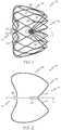
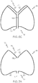
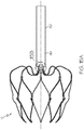
- Figure 1 shows a side elevational view of an expanded occlusion device 10 according to an embodiment.
- the device 10 comprises a proximal end 12 and a distal end 14 as well as a central axis L and a cage-like structure 16 formed of struts 18.
- the struts 18 are formed from a cut structure so that they are integrally connected with each other. As such, the struts 18 may form generally polygonal cells with vertices 26 at which the struts 18 merge into each other. It is also within the scope of the invention for the struts to form cells of other shapes.
- the struts 18 may have a substantially polygonal cross section although struts with cross-sections having non-polygonal shapes may also be used.
- the cage-like structure 16 forms a closed three dimensional frame, i.e., a frame closed on both ends 12, 14.
- the proximal strut ends 20 are connected at a proximal collar or hub 30.
- proximal collar 30 may be provided by ending the cuts between the struts 18 at a sufficient distance from the proximal end 12 so as to define a collar between the ends of the cuts and the proximal end 12.
- proximal collar 30 may be provided with an insert 34 for attaching the device 10 to a device tether or shaft (e.g., a tether wire).
- a device tether or shaft e.g., a tether wire
- distal strut ends 22 may be connected to each other within the cage-like structure 16. At least some of the distal strut ends 22 are bent inwardly so as to point in a direction towards the proximal end 12 of the cage-like structure 16. In the illustrated embodiment, the distal-most part of the distal strut ends 22 extend substantially parallel to the central axis L. The bent distal strut ends 22 thus form an atraumatic distal end 24 of the device 10.
- the struts 18 may be bent such that the distal end 14 of the device is atraumatic, preferably in both the constrained and the deployed state of the device.
- the cage-like structure 16 may have a tapered shape.
- the device may have a generally cone-like, for example, frusto-conical, or cylindrical shape.
- Such shapes may allow the device 10 to accommodate more closely to the natural shape of the LAA while exerting a tolerable outward contact pressure against the walls of the atrial appendage in order to provide an interference-like fit and hold the device 10 in place.
- the outward contact pressure may result from the designed springiness or elasticity of the cage-like structure.
- the device can also comprise one or more anchors, which may have any suitable form.
- the anchor may be pins or barbs 28 adapted for engaging the wall of the atrial appendage.
- the barbs 28 may extend from the struts 18 delimiting an outer perimeter of the cage-like structure 16.
- the barbs 28 can be formed integrally with the struts 18, e.g., by laser cutting.
- Barbs 28 may also be seen in the expanded occlusion device 10 of Figures 11-14 .
- the device may have as many as 6, 12, 18, 26 or any other suitable number of anchors.
- the distal strut ends 22 are connected to each other by a tube 32 that is crimped to the distal strut ends 22.
- the tube 32 may be fixed to the distal strut ends 22 by welding, soldering or adhesives.
- the strut ends may be secured to the tube at either end of the tube.
- the struts may extend the entire length of the tube or only part of the length of the tube.
- a centering pin 98 may be inserted into the tube 32 along with the ends of the distal strut ends 22 in order to arrange the ends around the inner wall of the tube 32.
- At least six, more typically at least ten, even more typically at least twelve or more struts 22 may be connected within the cage-like structure 16 to form the distal end 14 of the device.
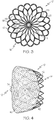
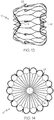
- Figure 3 which depicts a top elevational view of the device 10 illustrated in Figure 1 , for example, shows eighteen distal strut ends 22 connected within the cage-like structure 16.
- FIG. 4 shows a side elevational view of an expanded occlusion device 10 according to an embodiment.
- the device 10 includes a filter comprising a filter membrane 40 supported on the outer surface of the cage-like structure 16. More specifically, the filter membrane 40 is affixed at the proximal end 12 of the device. It should be noted, however, that, alternatively or additionally, a filter membrane may be provided at the distal end 14. Furthermore, the filter membrane(s) 40 may be provided along the outside of the cage-like structure 16 or therein.
- the filter membrane may be attached to the cage like structure 16 by any suitable technique, including hooks or barbs provided at the cage-like structure 16 and/or, as in the exemplary embodiment illustrated in Figure 4 , one or several filaments 42. Filaments 42 may be threaded through holes in the filter membrane 40 and tied to the struts 18 in order to secure the filter membrane 40 to the cage-like structure 16.
- the filter membrane may be made of a blood-permeable material having fluid conductive holes or channels extending across the membrane.
- the filter membrane may be fabricated from any suitable biocompatible material. These materials include, for example, ePFTE (e.g., Gore-Tex®), polyester (e.g., Dacron®), PTFE (e.g., Teflon®), silicone, urethane, metal fibers, and other biocompatible polymers.
- the hole sizes in the blood-permeable material may be chosen to be sufficiently small so that harmful-size emboli are filtered out from the blood flow between the appendage and the atrium. Suitable hole sizes may range, for example, from about 50 to about 400 microns in diameter.
- the filter membrane may be made of polyester (e.g., Dacron®) weave or knit having a nominal hole size of about 125 microns.
- the open area of the filter membrane i.e., the hole density
- portions of filter membrane may be coated or covered with an anticoagulant, such as heparin or another compound, or otherwise treated so that the treated portions acquire antithrombogenic properties to inhibit the formation of hole-clogging blood clots.
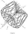
- Figure 5 depicts a perspective view of the device 10 illustrated in Figure 1 .
- the insert 34 has a threaded socket
- a tether wire 50 having a threaded fixture for engaging the insert 34 may be threaded into the socket in order to manipulate the device 10.
- the threaded socket may be suitable for rotatably engaging and/or releasing the occlusion device 10.
- An embodiment of an occlusion device 10 with a tether wire 50 having a threaded fixture 99 is also shown at 10 in Figure 15A and Figure 15B . It should be noted that, additionally or alternatively, any other suitable attachment may be provided.
- the device 10 shown in Figures 1 to 5 is a self-expanding device and is shown in its natural unconstrained expanded state.
- the cage-like structure 16 of the device 10 may be fabricated in different-sizes as necessary or appropriate for use in different sizes of atrial appendages.
- the illustrated structure may be, for example, about 25.4 mm (one inch) in diameter and about 25.4 mm (one inch) long in its natural expanded state.
- the device 10 may be compressed to a narrow diameter tubular shape and fitted into a narrow diameter catheter or delivery sheath.
- the device may be compressed to a diameter of less than 4 mm, more preferably of less than 3 mm and recover to its natural shape subsequently upon release from the sheath.
- the device may be compressed to a diameter of less 2 mm or less while for larger diameter vessels such as the aortic valve, the device may be compressed to a diameter of less than 5 mm.
- the struts 18 of the cage-like structure 16 may be made of any suitable elastic material, for example, nitinol or spring steel.
- shape memory materials such as nitinol
- the device may be provided with a memorized shape and then deformed to a reduced diameter shape. The device may restore itself to its memorized shape upon being heated to a transition temperature and/or having any restraints removed therefrom.
- the device may also be made from any other suitable biocompatible material including one or more polymers, one or more metals or combinations of polymer(s) and metal(s).
- suitable materials include biodegradable materials that are also biocompatible.
- biodegradable is used to denominate a material that undergoes breakdown or decomposition into harmless compounds as part of a normal biological process.
- Suitable biodegradable materials include polylactic acid, polyglycolic acid (PGA), collagen or other connective proteins or natural materials, polycaprolactone, hylauric acid, adhesive proteins, copolymers of these materials as well as composites and combinations thereof and combinations of other biodegradable polymers.
- polyester and polycarbonate copolymers examples include polyester and polycarbonate copolymers.
- suitable metals include, but are not limited to, stainless steel, titanium, tantalum, platinum, tungsten, gold and/or alloys of any of the above-mentioned metals.
- suitable alloys may include platinum-iridium alloys, cobalt-chromium alloys (e.g., Elgiloy and Phynox, MP35N), nickel-titanium alloys and nickel-titanium-platinum alloys.
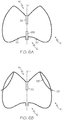
- Figures 6A to 6C , 7A and 7B illustrate further optional and/or essential features that may be provided and/or are provided in conjunction with the device 10 of Figures 1 to 5 . In order to avoid repetitions, only those features differing from the device described above will be addressed. Like reference numbers denominate the same or corresponding features.
- Figure 6A shows a schematic sectional view illustrating an embodiment of the cage-like structure 16 for devices 10.
- the proximal strut ends 20 may be connected within the cage like-structure 16.
- separate struts may be formed at the proximal end of the tubular structure when cutting it, which may then be bent towards the inside of the cage-like structure 16 and connected therein.
- the proximal strut ends 20 may be connected to each other by a tube 133 that is crimped on, soldered, adhered and/or welded to the proximal strut ends 20.
- a centering pin may be used in this context to arrange the proximal strut ends 20 evenly at the inner wall of the tube 133.
- a collar comprising several openings for receiving the proximal strut ends 20 may be employed.
- the proximal strut ends 20 may also be welded, soldered and/or adhered to each other directly.
- the distal strut ends 22 provide anchor 128.
- the distal strut ends 22 providing the anchor 128 extend through the cage-like structure 16, for example, from the inside of the cage-like structure 16 towards the outside.
- the anchor 128 may be provided in a central or distal part of the cage-like structure 16, for example, within the distal half or the most distal third thereof relative to the entire length of the cage-like structure 16 along the central axis L. It should be noted that such anchor are provided alternatively or additionally to the anchor 28 described above.
- Figure 6C depicts an embodiment of the cage-like structure 16 wherein some of the distal strut ends (i.e., distal strut ends 122) extend partially along the central axis L through the cage-like structure 16 towards the proximal end 12 of the device 10 to the proximal strut ends 20.
- the distal strut ends 122 may be connected to the proximal strut ends 20, for example, at a location where the proximal strut ends 20 are connected to each other (e.g., at the proximal collar 30).
- some or all of the distal strut ends 22 may extend through the cage like structure 16.
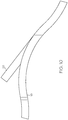
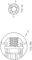
- FIG 7A shows a schematic sectional view illustrating the cage-like structure of another occlusion 10 device.
- the distal strut ends 22 are connected by a distal collar 132 comprising several openings 135 (see Figure 7c ) for receiving the distal strut ends 22.
- the openings 135 provided around the circumference of the distal collar 132 may extend at an angle ⁇ with respect to the central axis C of the collar 132.
- Axis C may be concentric with the central axis L of the device 10.
- the angle ⁇ may be between 0° and 70°.
- the distal collar 132 may be substantially cylindrical and/or may be provided with, for example, six, ten, twelve or eighteen or more openings 135, corresponding to the number of distal strut ends 22 to be attached to the collar. In some embodiments, a similar structure may be used to connect at least some of the proximal strut ends 20.
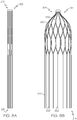
- Figures 8A to 8D show different stages of a method for manufacturing an occlusion device 10 according to the invention.
- Figure 8A illustrates a tubular structure 201 having a proximal end 212 and a distal end 214 and comprising a plurality of struts. The struts form loose distal strut ends 222 at the distal end of the device 214.
- the tubular structure 201 is produced by cutting a tubular nitinol body (not shown).
- the tubular structure may subsequently be heat treated and expanded by means of a mandrel (not shown) in order to provide a preform 301.
- a forming tool (not shown) may be used to provide the proximal strut ends 220 of the preform 301 with a desired shape, for example, the S-shape illustrated in Figure 8C .
- the proximal strut ends 220 are connected to each other at the proximal end 212.
- the loose distal strut ends 222 are then bent such that they have a directional component towards the proximal end 212. As shown in Figure 8C , the distal strut ends 222 are bent towards the inside of the preform 301, such that the loose distal strut ends 222 point in a direction towards the proximal end 212 of the preform 301.
- a tube 332 e.g., a hypotube
- the loose distal strut ends 222 are inserted into the tube 332.
- the hypotube 332 is then crimped and/or welded to the distal strut ends 222 in order to connect the ends to each other in a fixed manner. As further illustrated, the hypotube 332 is then cut and pulled back through the proximal end 212. The remaining crimped portion 32 holds the loose distal strut ends 222 together in a fixed and secure manner. Accordingly, the cage-like structure 16 with closed proximal and distal ends 12, 14 is formed (see Figure 8D ). In other embodiments, the loose distal strut ends 222 may be connected to each other by welding, soldering and/or by use of an adhesive. The tubular structure may be microblasted and/or electropolished.
- Figure 9 shows a tubular structure 201 that may be used for manufacturing an occlusion device 10 according to the present invention.
- the structure is illustrated in an unrolled and flattened state in order to depict the pattern formed by the struts.
- the tubular structure 201 is produced by laser cutting a tubular body or other suitable processes such as rolling an etched and/or cut sheet of material.
- the tubular structure 201 comprises struts 218 that may be adapted and configured to form the struts 18 of the device 10 illustrated in Figures 1 to 5 .
- the struts 218 extend from a proximal end 212 of the tubular structure 201 to a distal end 214 of said tubular structure 201.
- the proximal ends 220 of the struts 218 are configured and adapted to form the proximal end 12 of an occlusion device 10 according to the invention.
- the cuts between the proximal strut ends 220 of the struts 218 end at a distance from the proximal end 212 in order to leave a proximal collar 230, which integrally connects the proximal strut ends 220.
- the tubular structure 201 comprises distal strut ends 222.
- the distal strut ends 222 may terminate in loose ends at or proximate the distal end 214, which are indicated at 224 in Figure 9 .
- Figure 9 provides a schematic representation and does not show the entire length of distal strut ends 222, which may, optionally, account for approximately 20% to 65%, preferably approximately 30% to 55%, more preferably approximately 40% to 50%, and most preferably approximately 45% of the length of the tubular structure.
- the tubular structure 201 may comprise at least 6, at least 10, at least 12, or 18 or more loose distal strut ends.
- the struts forming the loose distal strut ends 222 may differ in wall thickness and/or strut width along their entire length or a section thereof.
- the distal strut ends 222 may have a first section 223 that is wider than a second section 224 (see Figure 9 ).
- a middle or a distal end section of distal strut ends 222 may be provided with a larger or smaller wall thickness and/or strut width. Varying the wall thickness and/or the strut width may allow configuring the bending properties of the distal strut ends 222, thereby determining, inter alia, the shape of the distal end 12 of device 10 as well as its radial stability.
- Anchoring struts 228 are optional and may be configured and adapted to provide the anchor 28 described above.
- the anchoring struts 228 may be formed when providing the tubular structure and may be integrally connected to struts 218.
- the invention in one or more embodiments, is directed to an occlusion device having proximal and distal ends and a central axis and comprising a cage-like structure formed of struts.
- the struts have proximal strut ends and distal strut ends.
- the struts extend towards the central axis and are connected to each other at their proximal strut ends.
- At the distal end of the device at least some of the struts are invaginated inward toward the central axis and the proximal end, and are connected to each other at their distal strut ends such that the distal strut ends are located proximal to the distal most part of the device.
- the invention is directed, in one or more embodiments, to an occlusion device having proximal and distal ends and a central axis and comprising a cage-like structure formed of struts.
- the struts have proximal strut ends and distal strut ends.
- the struts extend towards the central axis and are connected to each other at their proximal strut ends.
- At the distal end of the device at least some of the struts extend toward the central axis and the proximal end, and are connected to each other at their distal strut ends such that the distal strut ends are located proximal to the distal most part of the device.
- the invention relates to an occlusion device for use in an atrial appendage of a patient.
- the device may filter or otherwise modify or even block blood flow between an atrial appendage and the associated atrium.
- the device may be configured and adapted for deployment into an atrial appendage, i.e., the LAA.
- the device can also be placed across other apertures in the body, e.g., apertures through which blood flows.
- the device may also be adapted for use for RF based ablation.
- the device may have a proximal end and a distal end as well as a central axis and a cage-like structure formed of struts.
- the struts each have a proximal strut end and a distal strut end. At the proximal end of the device the struts extend towards the central axis and are connected to each other at their proximal strut ends. Further, at least some of the struts are connected to each other at their distal strut ends within the cage-like structure so that the struts form an atraumatic distal end of the device.
- the device may be self-expanding, i.e., it may form an elastic structure that expands from a compressed state to a predetermined expanded state when being unconstrained.
- the device In a compressed state, the device may take a narrow diameter tubular shape that is convenient for fitting the device into a narrow diameter catheter or delivery tube for percutaneous delivery.
- the cage-like structure typically forms a mesh or frame that is closed at both ends and surrounds a three dimensional space when the device is in an expanded state.
- the device may be designed to be expandable by means of an expansion mechanism for expanding the device in situ, for example, an inflatable balloon.
- the atraumatic distal end of the device according to the invention is atraumatic at least in its constrained delivery state, and more typically both in the constrained and a deployed state.
- the atraumatic distal end may be configured to enhance structural compatibility of the device with the atrial appendage during deployment as well as after implantation of the device. This could, desirably, reduce the risk of perforation. Also, it could allow for one or more recaptures of the device in the catheter and for full recapturability of the device by the catheter while having a lower likelihood for strut entanglement.
- the occlusion devices of the invention may be formed in several ways.
- the device is cut from a tubular body so as to provide the plurality of struts.
- the cuts may be formed in the tubular body, for example, by laser cutting, etching or other cutting techniques know in the art, particularly in the art of stent manufacturing.
- the struts of the device forming the cage-like structure may have a substantially polygonal cross-section or a cross-section of other, non-polygonal, shapes.
- the device in some embodiments of the invention, may also be characterized in that the struts form a plurality of closed polygonal cells having vertices, the struts merging into each other at said vertices.
- non-polygonal cells may be provided.
- the cage-like structure may be formed from a single cut structure, e.g., a single tubular body. In this way all struts are integrally connected with each other so that the cage-like structure represents a unitary body.
- the atraumatic distal end of the device comprises inwardly bent struts.
- at least some of the struts at the distal end are bent towards the inside of the cage-like structure.
- at least some, most or all of the ends or tips of the bent struts may be located inside the cage-like structure when the device is constrained and/or when the device is deployed.
- At least some of the ends of the bent struts point in a direction towards the proximal end of the cage-like structure.
- at least some, most or all of the struts are bent such that their distal strut ends extend substantially parallel to the central axis.
- such architecture may provide the device with a combination of performance characteristics that are normally difficult to obtain.
- the device may be constrained to a low profile and have a high radial strength, which may effectively ensure expansion upon deployment and prevent collapse after implantation.
- the cage-like structure or frame of the device according to the invention may be fabricated in different sizes, as necessary or appropriate for use in different sizes of atrial appendages or other suitable areas of the body.
- An exemplary cage-like structure may be about 25.4 mm (one inch) in diameter and about 25.4 mm (one inch) long in its natural expanded state. In the constrained state, it may be about 4 mm in diameter and 35 mm in length.
- the cage-like structure may have a tapered shape.
- the device may be tapered towards the distal end such that an outer diameter proximate the proximal end of the device is larger than an outer diameter proximate the distal end of the device.
- the device may have a generally conical, preferably frusto-conical shape. Other shapes, e.g., a generally cylindrical shape, are also feasible.
- the device When the device is expanded in an atrial appendage, it may be held in position by an outwardly directed contact pressure that the cage-like structure exerts against the walls of said atrial appendage, providing an interference-like fit of the device.
- the contact pressure may result from the designed springiness or elasticity of the cage-like structure or may be the result of plastic deformation.
- the device may comprise one or more anchors, which may engage the wall of the atrial appendage in order to ensure long-term stability in the implanted position.
- tissue-engaging anchors may be hooks, pins, barbs, wires with an atraumatic bulb, tips or other suitable structures.
- the anchor(s) may be in the form of stubs or barbs extending from the struts forming the cage-like structure and may be formed integrally therewith.
- the anchor(s) may extend from struts delimiting the outer diameter of the cage-like structure. According to the invention, at least some of the distal strut ends provide one or more anchors.
- At least some of the struts providing the anchor(s) may extend from the interior through the cage-like structure outwardly.
- at least some of the distal strut ends may extend from the inside of the cage-like structure towards the outside in order to provide the anchor(s).
- the anchor(s) may be provided in the central of distal part of the cage-like structure, for example, within the distal half or the most distal third of the device compared to the overall length from the proximal end to the distal end along the central axis. It should be noted that some of the anchor(s) are optional and may or may not be provided in the inventive devices according to the specific requirements determined by the intended use.
- the proximal strut ends and/or the distal strut ends may be connected to each other by one or a combination of: a tube that is crimped on and/or welded to the struts, a collar comprising several openings for receiving the ends of the struts, welding, soldering, use of adhesive, etc.
- a centering pin may be used to arrange the struts at the inner wall of the tube.
- the struts may also be arranged at the inner wall of the tube via the use of a shrink tube or by attachment with filament such as wire.
- the proximal strut ends may be integrally connected with each other. More specifically, the struts at the proximal end may remain connected to each other by a proximal collar or hub formed integrally therewith.
- the cuts between struts forming the proximal end of the device may be ended at a sufficient distance from the proximal end of the tubular structure in order to leave a proximal collar or hub to which at least some or all of the proximal strut ends forming the proximal end of the device are attached.
- proximal strut ends may be connected to each other within the cage-like structure.
- separated proximal strut ends may be formed at the proximal end of the tubular structure when cutting it, which may then be bent towards the inside of the cage like structure and connected to each other therein.
- some of the proximal strut ends are connected to each other outside the cage-like structure, for example by a proximal collar, while others are connected to each other within said cage-like structure. Accordingly, some of the proximal strut ends may be generally S-shaped while others may be generally C-shaped.
- At least some struts may extend from the distal end through the cage-like structure to the proximal end of the device, for example, along the central axis.
- the distal strut ends may be connected to the proximal strut ends, for example, where the proximal strut ends at the proximal end of the device are connected to each other.
- Such architectures may enhance stability of the device.
- the struts forming the distal end of the device may differ in wall thickness, strut width or both from the other struts of the cage-like structure.
- the wall thickness and/or the width of the struts forming the distal end may be smaller or larger than the wall thickness and/or the width of other struts of the cage-like structure.
- a segment of the struts forming the distal end may have a different (e.g., smaller/larger) wall thickness and/or width.
- the segment may be provided at any suitable location along the struts, for example, at a proximal, a middle or a distal end section thereof.
- the wall thickness and/or the strut width of the struts that form the distal end of the device may be varied in order to define the bending properties (e.g., the curvature and/or the radial strength) of the struts forming the distal end of the device.
- the wall thickness and/or the strut width of other struts forming the cage-like structure may be varied, for example, along their entire length or a segment thereof.
- the device may be provided with an insert that is configured for attaching the device to a tether or shaft (e.g., tether wire).
- the insert may have, for example, a threaded socket so that a tether wire can be releasably attached from a proximal direction.
- other attachment means are likewise feasible and will be apparent to those skilled in the art.
- the occlusion device according to the invention may additionally comprise a filter, for example, a filter membrane.
- the filter may be disposed along at least a portion of the cage-like structure, for example, along an outer or an inner segment thereof.
- the filter membrane may cover a proximal portion of the cage-like structure (e.g., a proximal "hemisphere" or end thereof).
- the filter membrane may span over the atrial facing surface of the device.
- the filter may be arranged at the distal portion of the device.
- the filter can be attached by any suitable technique.
- the filter may be supported by hooks or barbs extending from the cage-like structure.
- filaments may be used to tie the filter to the cells (e.g., at the vertices).
- the filter membrane may be held between struts forming said proximal end and the insert and/or between the proximal collar and the insert.
- the filter membrane may be made of a blood-permeable material having fluid conductive holes or channels extending across the membrane.
- the filter membrane may be fabricated from any suitable biocompatible material. These materials include, for example, ePFTE (e.g., Gore-Tex®), polyester (e.g., Dacron®), PTFE (e.g., Teflon®), silicone, urethane, metal fibers, and other biocompatible polymers.
- the sizes of the holes in the blood-permeable material may be chosen to be sufficiently small so that harmful-size emboli are filtered out from the blood flow between the appendage and the atrium. Suitable hole sizes may range, for example, from about 50 to about 400 microns in diameter.
- the filter membrane may be made of polyester (e.g., Dacron®) weave or knit having a nominal hole size of about 125 microns.
- the open area of the filter membrane i.e., the hole density
- portions of filter membrane may be coated or covered with an anticoagulant, such as heparin or another compound, or otherwise treated so that the treated portions acquire antithrombogenic properties to inhibit the formation of hole-clogging blood clots.
- the filter membrane assists in the occlusion of the atrial appendage. In particular, over time, the blood-clots captured by the filter, may lead to occlusion of the ostium of the atrial appendage.
- the struts forming the cage-like structure may be made of any suitable elastic material, for example, nitinol or spring steel. Also shape memory materials may be used (e.g., nitinol).
- the device may be provided with a memorized shape and then deformed to a reduced diameter shape. The device may restore itself to its memorized shape upon being heated to a transition temperature and having any restraints removed therefrom.
- the device of the invention may also be made from any other suitable biocompatible material including one or more polymers, one or more metals or combinations of polymer(s) and metal(s).
- suitable materials include biodegradable materials that are also biocompatible.
- a "biodegradable” material means that the material will undergo breakdown or decomposition into harmless compounds as part of a normal biological process.
- Suitable biodegradable materials include polylactic acid, polyglycolic acid (PGA), collagen or other connective proteins or natural materials, polycaprolactone, hylauric acid, adhesive proteins, copolymers of these materials as well as composites and combinations thereof and combinations of other biodegradable polymers.
- polyester and polycarbonate copolymers examples include polyester and polycarbonate copolymers.
- suitable metals include, but are not limited to, stainless steel, titanium, tantalum, platinum, tungsten, gold and alloys of any of the above-mentioned metals.
- suitable alloys may include platinum-iridium alloys, cobalt-chromium alloys including Elgiloy and Phynox, MP35N alloy, nickel-titanium alloys and nickel-titanium-platinum alloys.
- the device of the invention may be provided with a one or more therapeutic agents, whether in coating form or otherwise.
- therapeutic agent drug
- drug pharmaceutically active agent
- pharmaceutically active material pharmaceutically active material
- beneficial agent biologically active agent
- bioactive agent and other related terms may be used interchangeably herein and include genetic therapeutic agents, non-genetic therapeutic agents and cells.
- a drug may be used singly or in combination with other drugs.
- Drugs include genetic materials, non-genetic materials, and cells.
- a therapeutic agent may be a drug or other pharmaceutical product such as non-genetic agents, genetic agents, cellular material, etc.
- suitable non-genetic therapeutic agents include but are not limited to: antithrombogenic agents such as heparin, heparin derivatives, vascular cell growth promoters, growth factor inhibitors, etc.
- an agent includes a genetic therapeutic agent, such a genetic agent may include but is not limited to: DNA, RNA and their respective derivatives and/or components; hedgehog proteins, etc.
- the cellular material may include but is not limited to: cells of human origin and/or non-human origin as well as their respective components and/or derivatives thereof.
- active agents include, but are not limited to, antineoplastic, antiproliferative, antimitotic, antiinflammatory, antiplatelet, anticoagulant, antifibrin, antiproliferative, antibiotic, antioxidant, and antiallergic substances as well as combinations thereof.
- antineoplastic/antiproliferative/antimitotic agents include, but are not limited to, paclitaxel (e.g., TAXOL.RTM. by Bristol-Myers Squibb Co., Stamford, Conn.), the olimus family of drugs including sirolimus (rapamycin), biolimus (derivative of sirolimus), everolimus (derivative of sirolimus), zotarolimus (derivative of sirolimus) and tacrolimus, methotrexate, azathiprine, vincristine, vinblastine, 5-fluorouracil, doxorubicin hydrochloride, mitomycin, cisplatin, vinblastine, vincristine, epothilones, endostatin, angiostatin and thymidine kinase inhibitors.
- paclitaxel e.g., TAXOL.RTM. by Bristol-Myers Squibb Co., Stamford, Con
- the therapeutic agent can be dissolved in a solvent or a cosolvent blend, and an excipient may also be added to a coating composition.
- Suitable solvents include, but are not limited to, dimethyl formamide (DMF), butyl acetate, ethyl acetate, tetrahydrofuran (THF), dichloromethane (DCM), acetone, acetonitrile, dimethyl sulfoxide (DMSO), butyl acetate, etc.
- Suitable excipients include, but are not limited to, acetyl tri-n-butyl citrate (ATBC), acetyl triethyl citrate (ATEC), dimethyl tartarate (D, L, DL), diethyl tartarate (D, L, DL), dibutyl tartarate (D, L, DL), mono-, di- and tri-glycerol such as glycerol triacetate (triacetin), glycerol tributyrate (tributyrin), glycerol tricaprylate (tricarprin), sucrose octa acetate, glucose penta acetate (D, L, DL, and other C6 sugar variations), diethyl oxylate, diethyl malonate, diethyl maleate, diethyl succinate, dimethyl glutarate, diethyl glutarate, diethyl 3-hydroxy glutarate, ethyl gluconate (D, L, DL,
- Suitable biodegradable polymeric excipients may include polylactide, polylactide-co-glycolide, polycaprolactone, etc.
- Suitable polymeric excipients include, but are not limited to, block copolymers including styrenic block copolymers such as polystyrene-polyisobutylene-polystyrene triblock copolymer (SIBS), hydrogels such as polyethylene oxide, silicone rubber and/or any other suitable polymer material.
- SIBS polystyrene-polyisobutylene-polystyrene triblock copolymer
- hydrogels such as polyethylene oxide, silicone rubber and/or any other suitable polymer material.
- the device of the invention may be provided with or more lubricious coatings.
- lubricious materials include HDPE (High Density Polyethylene) or PTFE (Polytetrafluoroethylene), or a copolymer of tetrafluoroethylene with perfluoroalkyl vinyl ether (PFA) (more specifically, perfluoropropyl vinyl ether or perfluoromethyl vinyl ether), or the like.
- suitable lubricious polymers may include silicone and the like, hydrophilic polymers such as polyarylene oxides, polyvinylpyrolidones, polyvinylalcohols, hydroxy alkyl cellulosics, algins, saccharides, caprolactones, and the like, and mixtures and combinations thereof. Hydrophilic polymers may be blended among themselves or with formulated amounts of water insoluble compounds (including some polymers) to yield coatings with suitable lubricity, bonding, and solubility. Some other examples of such coatings and materials and methods used to create such coatings can be found in U.S. Pat. Nos. 8,048,060 , 7,544,381 , 7,914,809 , 6,673,053 , and 5,509,899 .
- the invention may also relate to tubular structures having patterns configured to form any of the occlusion devices disclosed above.
- the tubular structure may be microblasted and/or electropolished in order to enhance surface characteristics, long-term performance and/or biocompatibility.
- the present invention relates to a method of manufacturing an occlusion device for an atrial appendage.
- the method comprises the steps of (a) cutting a tubular body having proximal and distal ends to provide a tubular structure having struts, at least some of the struts at the distal end having loose distal strut ends; (b) expanding at least part of the tubular structure; (c) bending at least some of the loose distal strut ends towards the inside of said tubular structure such that the loose distal strut ends point in a direction towards the proximal end of the tubular structure; and (d) connecting at least some of the loose distal strut ends to each other.
- the method may further comprise the step of connecting the struts at their proximal strut ends to each other so as to form a cage-like structure.
- the cuts may not extend to the proximal end of the tubular body, thereby connecting the struts at the proximal end by a proximal collar that is formed integrally therewith.
- the distal strut ends may account for approximately 20% to 65%, preferably approximately 30% to 55%, more preferably approximately 40% to 50%, and most preferably approximately 45% of the length of the tubular structure.
- the tubular structure may comprise at least 6, at least 10, at least 12, or 18 distal strut ends.
- the struts forming the distal strut ends may differ in wall thickness and/or strut width along their entire length or a section thereof when compared to the other struts forming the tubular structure.
- laser cutting or other suitable machining processes may be used to cut the tubular body.
- the tubular structure may also be provided by rolling and welding an etched and/or cut sheet of material.
- the tubular structure may be heat treated and shaped over a mandrel in order to expand it and/or in order to provide the struts with a desired geometrical shape.
- a forming tool may be used for this purpose.
- the step of bending at least some of the distal strut ends may comprise inserting the distal struts ends into a tube located within the tubular structure.
- the tube may be inserted through the proximal end of the cut and expanded tubular structure and cut to length, if necessary.
- the step of connecting at least some of the distal strut ends to each other may comprise crimping and/or welding the tube to the loose ends, a type of connection which might be preferable from a manufacturing point of view.
- the distal strut ends may be connected to each other by welding, soldering and/or by use of adhesive.
- the method comprises the step of further bending at least some of the bent struts such that the distal strut ends extend to the outside of the tubular structure and form anchor, e.g., in the form of tissue-engaging hooks or barbs.
- At least some of the loose distal strut ends may be connected to the struts at the proximal end.
- at least some of the distal strut ends may be connected to the proximal collar.
- the method according to the invention may further comprise the step of bending at least some of the proximal strut ends towards the inside the tubular structure such that the proximal strut ends point in a direction towards the distal end of the tubular structure. At least some of these struts may be connected to each other, for example, inside the tubular structure.
- the method further comprises the step of bending at least some of the struts such that the ends extend to the outside of the tubular structure so as to provide an anchor.
- the device of the present invention may be implanted by any of the techniques known in the art, for example by the standard transseptal technique. A detailed description of methods that may be used with the device of the invention is provided, for example, in WO 03/063732 .
- the invention also may relate to methods for implanting any of the devices described above. Furthermore, the invention relates to a kit for implanting any of these devices, the kit comprising a device according to the invention and a corresponding implantation apparatus (e.g., an apparatus disclosed in WO 03/063732 ).
- a kit for implanting any of these devices the kit comprising a device according to the invention and a corresponding implantation apparatus (e.g., an apparatus disclosed in WO 03/063732 ).
Claims (17)
- Dispositif d'occlusion (10) pour un appendice auriculaire, le dispositif ayant des extrémités proximale (12) et distale (14) et un axe central (L) et comprenant une structure en forme de cage (16) formée avec des entretoises (18 ; 218), les entretoises (18 ; 218) ayant des extrémités d'entretoise proximales (20 ; 220) et des extrémités d'entretoise distales (22 ; 122 ; 222), dans lequel, au niveau de l'extrémité proximale (12) du dispositif (10), les entretoises (18 ; 218) s'étendent vers l'axe central (L) et sont raccordées entre elles au niveau de leurs extrémités d'entretoise proximales (20 ; 220), et dans lequel au moins certaines des entretoises (18 ; 218) sont raccordées entre elles au niveau de leurs extrémités d'entretoise distales (22 ; 122 ; 222) à l'intérieur de la structure en forme de cage (16) de sorte que les entretoises (18 ; 218) forment une extrémité distale atraumatique (24) du dispositif (10),
caractérisé en ce qu'au moins certaines des extrémités d'entretoise distales (22 ; 122 ; 222) fournissent un ancrage (128) et dans lequel au moins certaines des entretoises (18 ; 218) fournissant l'ancrage (128) s'étendent à travers la structure en forme de cage (16). - Dispositif d'occlusion (10) selon la revendication 1, dans lequel la structure en forme de cage (16) est découpée à partir d'un corps tubulaire unitaire.
- Dispositif d'occlusion (10) selon la revendication 1, dans lequel les entretoises (18 ; 218) ont une section transversale sensiblement polygonale.
- Dispositif d'occlusion (10) selon la revendication 1, dans lequel les entretoises (18 ; 218) forment une pluralité de cellules polygonales fermées ayant des sommets (26) et dans lequel les entretoises (18 ; 218) fusionnent entre elles au niveau desdits sommets (26).
- Dispositif d'occlusion (10) selon la revendication 1, dans lequel l'extrémité distale atraumatique (24) du dispositif (10) comprend des entretoises pliées vers l'intérieur (18 ; 218).
- Dispositif d'occlusion (10) selon la revendication 5, dans lequel au moins certaines des extrémités des entretoises pliées (18 ; 218) pointent dans une direction vers l'extrémité proximale (12) de la structure en forme de cage (16).
- Dispositif d'occlusion (10) selon la revendication 5, dans lequel au moins certaines des entretoises (18 ; 218) sont pliées de sorte que leurs extrémités d'entretoise distales (22 ; 122 ; 222) s'étendent de manière sensiblement parallèle à l'axe central (L).
- Dispositif d'occlusion (10) selon la revendication 1, dans lequel au moins certaines des extrémités d'entretoise distales (22 ; 122 ; 222) sont raccordées aux extrémités d'entretoise proximales (20 ; 220).
- Dispositif d'occlusion (10) selon la revendication 1, dans lequel les extrémités d'entretoise proximales (20 ; 220) sont raccordées entre elles à l'extérieur de la structure en forme de cage (16).
- Dispositif d'occlusion (10) selon la revendication 1, dans lequel les extrémités d'entretoise proximales (20 ; 220) sont raccordées entre elles à l'intérieur de la structure en forme de cage (16).
- Dispositif d'occlusion (10) selon la revendication 1, dans lequel les extrémités d'entretoise proximales (20 ; 220) sont raccordées entre elles par un collier proximal (30 ; 230) formé de manière solidaire avec ces dernières.
- Dispositif d'occlusion (10) selon la revendication 1, dans lequel les extrémités d'entretoise distales (22 ; 122 ; 222) sont raccordées entre elles par un tube (32 ; 332) qui est serti sur et/ou soudé sur les extrémités d'entretoise distales (22 ; 122 ; 222), et/ou un collier (132) comprenant plusieurs ouvertures (135) pour recevoir les extrémités d'entretoise distales (22 ; 122 ; 222), et/ou soudage et/ou brasage et/ou un tube thermo-rétractable et/ou un filament et/ou un adhésif.
- Dispositif d'occlusion (10) selon la revendication 1, dans lequel les extrémités d'entretoise distales (22 ; 122 ; 222) diffèrent en partie ou complètement du point de vue de l'épaisseur de paroi et/ou de la largeur d'entretoise des autres entretoises (18 ; 218) de la structure en forme de cage (16).
- Dispositif d'occlusion (10) selon la revendication 1, dans lequel la structure en forme de cage (16) est formée avec une structure découpée unique.
- Dispositif d'occlusion (10) selon la revendication 1, comprenant en outre un filtre.
- Dispositif d'occlusion (10) selon la revendication 1, comprenant en outre un insert fileté (34) au niveau de l'extrémité proximale (12).
- Procédé pour fabriquer un dispositif d'occlusion (10) pour un appendice auriculaire selon l'une quelconque des revendications 1 à 16, comprenant les étapes consistant à :a) couper un corps tubulaire ayant des extrémités proximale et distale pour fournir une structure tubulaire (201) ayant des entretoises (18 ; 218), au moins certaines des entretoises (18 ; 218) au niveau de l'extrémité distale ayant des extrémités d'entretoise distales lâches (22 ; 122 ; 222) ;b) faire subir une expansion à au moins une partie de la structure tubulaire (201) ;c) plier au moins certaines des extrémités d'entretoise distales (22 ; 122 ; 222) lâches vers l'intérieur de ladite structure tubulaire (201) de sorte que les extrémités d'entretoise distales (22 ; 122 ; 222) lâches se dirigent dans une direction vers l'extrémité proximale (212) de la structure tubulaire (201) ;d) raccorder au moins certaines des extrémités d'entretoise distales (22 ; 122 ; 222) lâches entre elles ; ete) plier au moins certaines des entretoises (18 ; 218) de sorte que les extrémités (22 ; 122 ; 222) s'étendent vers l'extérieur de la structure tubulaire (201) afin de fournir un ancrage (228).
Priority Applications (2)
| Application Number | Priority Date | Filing Date | Title |
|---|---|---|---|
| EP17162401.8A EP3213695B1 (fr) | 2012-07-13 | 2013-07-11 | Dispositif d'occlusion d'un appendice auriculaire |
| EP21171829.1A EP3900648A1 (fr) | 2012-07-13 | 2013-07-11 | Dispositif d'occlusion d'un appendice auriculaire |
Applications Claiming Priority (2)
| Application Number | Priority Date | Filing Date | Title |
|---|---|---|---|
| US201261671433P | 2012-07-13 | 2012-07-13 | |
| PCT/US2013/050060 WO2014011865A1 (fr) | 2012-07-13 | 2013-07-11 | Dispositif d'occlusion pour un appendice auriculaire |
Related Child Applications (2)
| Application Number | Title | Priority Date | Filing Date |
|---|---|---|---|
| EP21171829.1A Division EP3900648A1 (fr) | 2012-07-13 | 2013-07-11 | Dispositif d'occlusion d'un appendice auriculaire |
| EP17162401.8A Division EP3213695B1 (fr) | 2012-07-13 | 2013-07-11 | Dispositif d'occlusion d'un appendice auriculaire |
Publications (2)
| Publication Number | Publication Date |
|---|---|
| EP2872051A1 EP2872051A1 (fr) | 2015-05-20 |
| EP2872051B1 true EP2872051B1 (fr) | 2017-03-29 |
Family
ID=48856996
Family Applications (3)
| Application Number | Title | Priority Date | Filing Date |
|---|---|---|---|
| EP13740155.0A Active EP2872051B1 (fr) | 2012-07-13 | 2013-07-11 | Dispositif d'occlusion pour un appendice auriculaire |
| EP21171829.1A Pending EP3900648A1 (fr) | 2012-07-13 | 2013-07-11 | Dispositif d'occlusion d'un appendice auriculaire |
| EP17162401.8A Active EP3213695B1 (fr) | 2012-07-13 | 2013-07-11 | Dispositif d'occlusion d'un appendice auriculaire |
Family Applications After (2)
| Application Number | Title | Priority Date | Filing Date |
|---|---|---|---|
| EP21171829.1A Pending EP3900648A1 (fr) | 2012-07-13 | 2013-07-11 | Dispositif d'occlusion d'un appendice auriculaire |
| EP17162401.8A Active EP3213695B1 (fr) | 2012-07-13 | 2013-07-11 | Dispositif d'occlusion d'un appendice auriculaire |
Country Status (8)
| Country | Link |
|---|---|
| US (1) | US20140018841A1 (fr) |
| EP (3) | EP2872051B1 (fr) |
| JP (1) | JP6133983B2 (fr) |
| CN (2) | CN104768476B (fr) |
| CA (1) | CA2878167C (fr) |
| ES (1) | ES2626878T3 (fr) |
| IN (1) | IN2014DN10863A (fr) |
| WO (1) | WO2014011865A1 (fr) |
Cited By (6)
| Publication number | Priority date | Publication date | Assignee | Title |
|---|---|---|---|---|
| US10617425B2 (en) | 2014-03-10 | 2020-04-14 | Conformal Medical, Inc. | Devices and methods for excluding the left atrial appendage |
| US10722240B1 (en) | 2019-02-08 | 2020-07-28 | Conformal Medical, Inc. | Devices and methods for excluding the left atrial appendage |
| US11026695B2 (en) | 2016-10-27 | 2021-06-08 | Conformal Medical, Inc. | Devices and methods for excluding the left atrial appendage |
| US11399842B2 (en) | 2013-03-13 | 2022-08-02 | Conformal Medical, Inc. | Devices and methods for excluding the left atrial appendage |
| US11426172B2 (en) | 2016-10-27 | 2022-08-30 | Conformal Medical, Inc. | Devices and methods for excluding the left atrial appendage |
| US11717303B2 (en) | 2013-03-13 | 2023-08-08 | Conformal Medical, Inc. | Devices and methods for excluding the left atrial appendage |
Families Citing this family (59)
| Publication number | Priority date | Publication date | Assignee | Title |
|---|---|---|---|---|
| WO2008151204A1 (fr) | 2007-06-04 | 2008-12-11 | Sequent Medical Inc. | Procédés et dispositifs pour le traitement de défauts vasculaires |
| EP2279023B1 (fr) * | 2008-05-02 | 2020-12-02 | Sequent Medical, Inc. | Dispositifs filamentaires pour le traitement de défauts vasculaires |
| US20180049731A1 (en) * | 2010-04-29 | 2018-02-22 | Muffin Incorporated | Closing device for tissue openings |
| US10568628B2 (en) * | 2017-05-23 | 2020-02-25 | Muffin Incorporated | Closing device for tissue openings |
| US9744033B2 (en) | 2011-04-01 | 2017-08-29 | W.L. Gore & Associates, Inc. | Elastomeric leaflet for prosthetic heart valves |
| US9554806B2 (en) | 2011-09-16 | 2017-01-31 | W. L. Gore & Associates, Inc. | Occlusive devices |
| US10959715B2 (en) | 2012-10-31 | 2021-03-30 | W. L. Gore & Associates, Inc. | Devices and methods related to deposited support structures |
| US11744594B2 (en) * | 2012-11-16 | 2023-09-05 | W.L. Gore & Associates, Inc. | Space filling devices |
| US10675012B2 (en) | 2012-11-16 | 2020-06-09 | W. L. Gore & Associates, Inc. | Joint assembly for medical devices |
| US11911258B2 (en) * | 2013-06-26 | 2024-02-27 | W. L. Gore & Associates, Inc. | Space filling devices |
| US9078658B2 (en) | 2013-08-16 | 2015-07-14 | Sequent Medical, Inc. | Filamentary devices for treatment of vascular defects |
| US9955976B2 (en) | 2013-08-16 | 2018-05-01 | Sequent Medical, Inc. | Filamentary devices for treatment of vascular defects |
| US9730701B2 (en) | 2014-01-16 | 2017-08-15 | Boston Scientific Scimed, Inc. | Retrieval wire centering device |
| US9629635B2 (en) | 2014-04-14 | 2017-04-25 | Sequent Medical, Inc. | Devices for therapeutic vascular procedures |
| JP6740214B2 (ja) * | 2014-09-12 | 2020-08-12 | カラク アーゲー | オクルーダー |
| CN105796148B (zh) | 2014-12-31 | 2018-06-05 | 先健科技(深圳)有限公司 | 左心耳封堵器 |
| EP3294150B1 (fr) | 2015-05-14 | 2021-12-15 | W. L. Gore & Associates, Inc. | Dispositifs d'occlusion d'appendice auriculaire |
| EP3310264A1 (fr) * | 2015-06-19 | 2018-04-25 | Koninklijke Philips N.V. | Dispositif médical implantable et système de chauffage de tissu |
| CN105054985B (zh) * | 2015-07-28 | 2018-05-01 | 杭州诺茂医疗科技有限公司 | 一种改进的左心耳封堵器 |
| EP3359771B1 (fr) | 2015-12-16 | 2021-06-02 | Halliburton Energy Services, Inc. | Tomographie à impédance électrique utilisant un réseau commutable |
| CN106923884B (zh) * | 2015-12-31 | 2018-12-21 | 先健科技(深圳)有限公司 | 左心耳封堵器 |
| US11389283B2 (en) * | 2016-05-11 | 2022-07-19 | W. L. Gore & Associates, Inc. | Filter and occluder systems and associated methods and devices |
| CN106994030B (zh) * | 2016-06-15 | 2020-03-10 | 先健科技(深圳)有限公司 | 左心耳封堵器 |
| EP4129210A1 (fr) * | 2016-07-22 | 2023-02-08 | Cornell University | Dispositif d'occlusion d'un appendice de l'auricule gauche |
| US10383725B2 (en) | 2016-08-11 | 2019-08-20 | 4C Medical Technologies, Inc. | Heart chamber prosthetic valve implant with base, mesh and dome sections with single chamber anchoring for preservation, supplementation and/or replacement of native valve function |
| CN106333725A (zh) * | 2016-09-27 | 2017-01-18 | 张雯 | 一种左心耳封堵器以及左心耳封堵装置 |
| WO2018089311A1 (fr) | 2016-11-08 | 2018-05-17 | Cardiac Pacemakers, Inc | Dispositif médical implantable pour déploiement auriculaire |
| US10653523B2 (en) | 2017-01-19 | 2020-05-19 | 4C Medical Technologies, Inc. | Systems, methods and devices for delivery systems, methods and devices for implanting prosthetic heart valves |
| US10561495B2 (en) | 2017-01-24 | 2020-02-18 | 4C Medical Technologies, Inc. | Systems, methods and devices for two-step delivery and implantation of prosthetic heart valve |
| CN107049373B (zh) * | 2017-02-08 | 2023-09-26 | 宁波迪创医疗科技有限公司 | 封堵器 |
| CN106691521B (zh) * | 2017-02-08 | 2023-08-04 | 宁波迪创医疗科技有限公司 | 一种封堵器 |
| EP3600068B1 (fr) * | 2017-03-24 | 2024-01-24 | Microvention, Inc. | Dispositifs pour embolisation de structures corporelles |
| CN106955135A (zh) * | 2017-04-07 | 2017-07-18 | 上海申淇医疗科技有限公司 | 一种封堵器阻流膜及其制造方法 |
| CN110831520B (zh) | 2017-04-27 | 2022-11-15 | 波士顿科学国际有限公司 | 具有织物保持倒钩的闭塞医疗装置 |
| CN108938034A (zh) * | 2017-05-23 | 2018-12-07 | 杭州诺茂医疗科技有限公司 | 一种改进密封效果的左心耳封堵器及其制备方法 |
| CN109419548A (zh) * | 2017-08-21 | 2019-03-05 | 上海普实医疗器械科技有限公司 | 左心耳封堵器及其制造方法 |
| EP3459469A1 (fr) | 2017-09-23 | 2019-03-27 | Universität Zürich | Dispositif occlusif médical |
| US11173023B2 (en) * | 2017-10-16 | 2021-11-16 | W. L. Gore & Associates, Inc. | Medical devices and anchors therefor |
| EP3700436B1 (fr) | 2017-10-27 | 2023-03-08 | Boston Scientific Scimed Inc. | Dispositif médical occlusif doté d'ensembles d'amortissement |
| US11191547B2 (en) | 2018-01-26 | 2021-12-07 | Syntheon 2.0, LLC | Left atrial appendage clipping device and methods for clipping the LAA |
| US11284902B2 (en) | 2018-02-01 | 2022-03-29 | Boston Scientific Scimed, Inc. | Method of making a vascular occlusion device |
| CN111867490B (zh) | 2018-02-14 | 2024-01-30 | 波士顿科学医学有限公司 | 闭塞医疗装置 |
| WO2019222382A1 (fr) * | 2018-05-15 | 2019-11-21 | Boston Scientific Scimed, Inc. | Dispositif médical occlusif avec revêtement polymère chargé |
| WO2019237004A1 (fr) * | 2018-06-08 | 2019-12-12 | Boston Scientific Scimed, Inc. | Dispositif médical pourvu d'un élément occlusif |
| WO2020041437A1 (fr) * | 2018-08-21 | 2020-02-27 | Boston Scientific Scimed, Inc. | Élément saillant avec ardillon pour dispositifs cardiovasculaires |
| US11857441B2 (en) | 2018-09-04 | 2024-01-02 | 4C Medical Technologies, Inc. | Stent loading device |
| EP3908208A4 (fr) | 2019-03-15 | 2022-10-19 | Sequent Medical, Inc. | Dispositifs filamenteux munis d'une articulation flexible pour le traitement d'anomalies vasculaires |
| CN113573765A (zh) | 2019-03-15 | 2021-10-29 | 后续医疗股份有限公司 | 用于治疗血管缺陷的丝装置 |
| CN113556985A (zh) | 2019-03-15 | 2021-10-26 | 后续医疗股份有限公司 | 用于治疗血管缺陷的丝装置 |
| CN113873957A (zh) | 2019-03-25 | 2021-12-31 | 拉米纳公司 | 用于处理左心耳的装置和系统 |
| CN110522486B (zh) * | 2019-04-22 | 2021-04-09 | 上海佐心医疗科技有限公司 | 用于左心耳的封堵支架 |
| US10925615B2 (en) | 2019-05-03 | 2021-02-23 | Syntheon 2.0, LLC | Recapturable left atrial appendage clipping device and methods for recapturing a left atrial appendage clip |
| EP3998962A1 (fr) | 2019-07-17 | 2022-05-25 | Boston Scientific Scimed, Inc. | Implant d'appendice auriculaire gauche à revêtement continu |
| EP3986284A1 (fr) | 2019-08-30 | 2022-04-27 | Boston Scientific Scimed, Inc. | Implant d'appendice auriculaire gauche ayant un disque d'étanchéité |
| CN114641242A (zh) | 2019-09-26 | 2022-06-17 | 苏黎世大学 | 左心耳闭塞装置 |
| US11963708B2 (en) | 2019-12-27 | 2024-04-23 | Lifetech Scientific (Shenzhen) Co., Ltd. | Left atrial appendage occluder and occlusion system |
| US11931253B2 (en) | 2020-01-31 | 2024-03-19 | 4C Medical Technologies, Inc. | Prosthetic heart valve delivery system: ball-slide attachment |
| EP4125634A1 (fr) | 2020-03-24 | 2023-02-08 | Boston Scientific Scimed Inc. | Système médical pour le traitement d'un appendice auriculaire gauche |
| JP2024516820A (ja) * | 2021-04-27 | 2024-04-17 | ボストン サイエンティフィック サイムド,インコーポレイテッド | 左心耳インプラント |
Family Cites Families (34)
| Publication number | Priority date | Publication date | Assignee | Title |
|---|---|---|---|---|
| US5509899A (en) | 1994-09-22 | 1996-04-23 | Boston Scientific Corp. | Medical device with lubricious coating |
| US6443972B1 (en) * | 1997-11-19 | 2002-09-03 | Cordis Europa N.V. | Vascular filter |
| US6152144A (en) * | 1998-11-06 | 2000-11-28 | Appriva Medical, Inc. | Method and device for left atrial appendage occlusion |
| US7044134B2 (en) * | 1999-11-08 | 2006-05-16 | Ev3 Sunnyvale, Inc | Method of implanting a device in the left atrial appendage |
| US6673053B2 (en) | 1999-05-07 | 2004-01-06 | Scimed Life Systems, Inc. | Hydrophilic lubricity coating for medical devices comprising an antiblock agent |
| US6730119B1 (en) * | 2000-10-06 | 2004-05-04 | Board Of Regents Of The University Of Texas System | Percutaneous implantation of partially covered stents in aneurysmally dilated arterial segments with subsequent embolization and obliteration of the aneurysm cavity |
| US20030032976A1 (en) * | 2001-05-21 | 2003-02-13 | Boucek Mark M. | Catheter deployed partial occlusion devices and methods |
| US20040111147A1 (en) * | 2002-12-03 | 2004-06-10 | Rabkin Dmitry J. | Temporary, repositionable or retrievable intraluminal devices |
| EP1469790B1 (fr) | 2002-01-25 | 2016-10-19 | Atritech, Inc. | Systemes de filtration sanguine pour auricule cardiaque |
| US7001369B2 (en) | 2003-03-27 | 2006-02-21 | Scimed Life Systems, Inc. | Medical device |
| US7288084B2 (en) | 2003-04-28 | 2007-10-30 | Boston Scientific Scimed, Inc. | Drug-loaded medical device |
| US7597704B2 (en) * | 2003-04-28 | 2009-10-06 | Atritech, Inc. | Left atrial appendage occlusion device with active expansion |
| US7544381B2 (en) | 2003-09-09 | 2009-06-09 | Boston Scientific Scimed, Inc. | Lubricious coatings for medical device |
| AU2005232562B2 (en) * | 2004-04-08 | 2009-05-07 | St. Jude Medical, Cardiology Division, Inc. | Flange occlusion devices and methods |
| US7914809B2 (en) | 2005-08-26 | 2011-03-29 | Boston Scientific Scimed, Inc. | Lubricious composites for medical devices |
| ATE474503T1 (de) * | 2005-11-11 | 2010-08-15 | Occlutech Gmbh | Occlusionsinstrument zum verschliessen eines herzohres |
| US8870913B2 (en) * | 2006-03-31 | 2014-10-28 | W.L. Gore & Associates, Inc. | Catch system with locking cap for patent foramen ovale (PFO) occluder |
| ATE530210T1 (de) | 2006-09-18 | 2011-11-15 | Boston Scient Ltd | Endoprothesen |
| JP2010503482A (ja) | 2006-09-18 | 2010-02-04 | ボストン サイエンティフィック リミテッド | 内部人工器官 |
| EP2263605A1 (fr) * | 2006-11-20 | 2010-12-22 | SeptRx, Inc. | Dispositif et procédé d'empêchement le debit de l'embolie non souhaité entre veines et artères |
| ES2353827T3 (es) * | 2006-11-20 | 2011-03-07 | Septrx, Inc. | Dispositivo para la prevención del paso no deseado de émbolos desde un depósito sanguíneo venoso a un depósito sanguíneo arterial. |
| WO2008151204A1 (fr) * | 2007-06-04 | 2008-12-11 | Sequent Medical Inc. | Procédés et dispositifs pour le traitement de défauts vasculaires |
| US20090028785A1 (en) | 2007-07-23 | 2009-01-29 | Boston Scientific Scimed, Inc. | Medical devices with coatings for delivery of a therapeutic agent |
| WO2009036014A2 (fr) | 2007-09-10 | 2009-03-19 | Boston Scientific Scimed, Inc. | Dispositifs médicaux avec matériau bioadhésif susceptible d'être activé |
| US9414842B2 (en) * | 2007-10-12 | 2016-08-16 | St. Jude Medical, Cardiology Division, Inc. | Multi-component vascular device |
| US10123803B2 (en) * | 2007-10-17 | 2018-11-13 | Covidien Lp | Methods of managing neurovascular obstructions |
| WO2010030728A2 (fr) | 2008-09-12 | 2010-03-18 | Boston Scientific Scimed, Inc. | Dispositifs et systèmes pour distribuer des agents thérapeutiques à des lumières corporelles |
| WO2010042471A2 (fr) | 2008-10-07 | 2010-04-15 | Boston Scientific Scimed, Inc. | Dispositifs médicaux pour administration d'agents thérapeutiques à des lumières corporelles |
| US20110054515A1 (en) * | 2009-08-25 | 2011-03-03 | John Bridgeman | Device and method for occluding the left atrial appendage |
| CA2778639A1 (fr) * | 2009-11-05 | 2011-05-12 | Sequent Medical Inc. | Dispositifs filamentaires multicouches pour le traitement d'anomalies vasculaires |
| CN201814682U (zh) * | 2010-09-16 | 2011-05-04 | 先健科技(深圳)有限公司 | 封堵器 |
| US20120095396A1 (en) | 2010-10-18 | 2012-04-19 | Boston Scientific Scimed, Inc. | Drug Eluting Medical Device Utilizing Bioadhesives |
| CN202143640U (zh) * | 2011-06-01 | 2012-02-15 | 先健科技(深圳)有限公司 | 左心耳封堵器 |
| CN103917169B (zh) * | 2011-11-09 | 2016-11-09 | 波士顿科学国际有限公司 | 封堵器 |
-
2013
- 2013-07-11 EP EP13740155.0A patent/EP2872051B1/fr active Active
- 2013-07-11 ES ES13740155.0T patent/ES2626878T3/es active Active
- 2013-07-11 CN CN201380037222.4A patent/CN104768476B/zh active Active
- 2013-07-11 CA CA2878167A patent/CA2878167C/fr not_active Expired - Fee Related
- 2013-07-11 EP EP21171829.1A patent/EP3900648A1/fr active Pending
- 2013-07-11 EP EP17162401.8A patent/EP3213695B1/fr active Active
- 2013-07-11 CN CN201910423025.5A patent/CN110115608B/zh active Active
- 2013-07-11 JP JP2015521803A patent/JP6133983B2/ja active Active
- 2013-07-11 IN IN10863DEN2014 patent/IN2014DN10863A/en unknown
- 2013-07-11 WO PCT/US2013/050060 patent/WO2014011865A1/fr active Application Filing
- 2013-07-11 US US13/939,383 patent/US20140018841A1/en not_active Abandoned
Non-Patent Citations (1)
| Title |
|---|
| None * |
Cited By (8)
| Publication number | Priority date | Publication date | Assignee | Title |
|---|---|---|---|---|
| US11399842B2 (en) | 2013-03-13 | 2022-08-02 | Conformal Medical, Inc. | Devices and methods for excluding the left atrial appendage |
| US11717303B2 (en) | 2013-03-13 | 2023-08-08 | Conformal Medical, Inc. | Devices and methods for excluding the left atrial appendage |
| US10617425B2 (en) | 2014-03-10 | 2020-04-14 | Conformal Medical, Inc. | Devices and methods for excluding the left atrial appendage |
| US11026695B2 (en) | 2016-10-27 | 2021-06-08 | Conformal Medical, Inc. | Devices and methods for excluding the left atrial appendage |
| US11426172B2 (en) | 2016-10-27 | 2022-08-30 | Conformal Medical, Inc. | Devices and methods for excluding the left atrial appendage |
| US11786256B2 (en) | 2016-10-27 | 2023-10-17 | Conformal Medical, Inc. | Devices and methods for excluding the left atrial appendage |
| US10722240B1 (en) | 2019-02-08 | 2020-07-28 | Conformal Medical, Inc. | Devices and methods for excluding the left atrial appendage |
| US11116510B2 (en) | 2019-02-08 | 2021-09-14 | Conformal Medical, Inc. | Devices and methods for excluding the left atrial appendage |
Also Published As
| Publication number | Publication date |
|---|---|
| CN110115608B (zh) | 2023-03-24 |
| IN2014DN10863A (fr) | 2015-09-11 |
| ES2626878T3 (es) | 2017-07-26 |
| WO2014011865A1 (fr) | 2014-01-16 |
| EP2872051A1 (fr) | 2015-05-20 |
| EP3213695A3 (fr) | 2017-11-08 |
| EP3900648A1 (fr) | 2021-10-27 |
| CN104768476B (zh) | 2019-05-31 |
| EP3213695B1 (fr) | 2021-05-05 |
| CN110115608A (zh) | 2019-08-13 |
| CA2878167C (fr) | 2018-03-13 |
| CA2878167A1 (fr) | 2014-01-16 |
| JP2015522360A (ja) | 2015-08-06 |
| JP6133983B2 (ja) | 2017-05-24 |
| CN104768476A (zh) | 2015-07-08 |
| EP3213695A2 (fr) | 2017-09-06 |
| US20140018841A1 (en) | 2014-01-16 |
| WO2014011865A8 (fr) | 2014-03-06 |
Similar Documents
| Publication | Publication Date | Title |
|---|---|---|
| EP2872051B1 (fr) | Dispositif d'occlusion pour un appendice auriculaire | |
| US9861370B2 (en) | Occlusion device | |
| ES2211220T3 (es) | Protesis auto expandible con recubrimiento biocompatible. | |
| EP3457985B1 (fr) | Libération de stent | |
| CN101102728B (zh) | 具有可自展开部分的支架 | |
| US8778011B2 (en) | Soft crowns | |
| EP1532663B1 (fr) | Procedes de fabrication de dispositifs a films minces tridimensionnels | |
| JP4971580B2 (ja) | ステントおよびステントの製造方法 | |
| JP6124026B2 (ja) | 末梢用途のための改良されたスキャフォールド | |
| EP1974701B1 (fr) | Endoprothèses implantables incorporant des marqueurs radiopaques | |
| US9561122B2 (en) | Vascular device for aneurysm treatment and providing blood flow into a perforator vessel | |
| JP2010532683A (ja) | 生体吸収性膜を備えたステント | |
| US20210128329A1 (en) | Tracheal stent | |
| US20190262151A1 (en) | Woven stent device with capped ends and manufacturing method | |
| JP4526589B2 (ja) | カバードステント | |
| JP2005074154A (ja) | 生体留置用補綴物組立体およびその製造方法 |
Legal Events
| Date | Code | Title | Description |
|---|---|---|---|
| PUAI | Public reference made under article 153(3) epc to a published international application that has entered the european phase |
Free format text: ORIGINAL CODE: 0009012 |
|
| 17P | Request for examination filed |
Effective date: 20150110 |
|
| AK | Designated contracting states |
Kind code of ref document: A1 Designated state(s): AL AT BE BG CH CY CZ DE DK EE ES FI FR GB GR HR HU IE IS IT LI LT LU LV MC MK MT NL NO PL PT RO RS SE SI SK SM TR |
|
| AX | Request for extension of the european patent |
Extension state: BA ME |
|
| RIN1 | Information on inventor provided before grant (corrected) |
Inventor name: PEIFFER, DENNIS A Inventor name: LEY, TIMOTHY J Inventor name: TISCHLER, BRIAN JOSEPH Inventor name: CLARK, CHRISTOPHER J Inventor name: CHAU, THYNA M. |
|
| DAX | Request for extension of the european patent (deleted) | ||
| 17Q | First examination report despatched |
Effective date: 20160114 |
|
| GRAP | Despatch of communication of intention to grant a patent |
Free format text: ORIGINAL CODE: EPIDOSNIGR1 |
|
| INTG | Intention to grant announced |
Effective date: 20161005 |
|
| GRAS | Grant fee paid |
Free format text: ORIGINAL CODE: EPIDOSNIGR3 |
|
| STAA | Information on the status of an ep patent application or granted ep patent |
Free format text: STATUS: GRANT OF PATENT IS INTENDED |
|
| GRAA | (expected) grant |
Free format text: ORIGINAL CODE: 0009210 |
|
| STAA | Information on the status of an ep patent application or granted ep patent |
Free format text: STATUS: THE PATENT HAS BEEN GRANTED |
|
| AK | Designated contracting states |
Kind code of ref document: B1 Designated state(s): AL AT BE BG CH CY CZ DE DK EE ES FI FR GB GR HR HU IE IS IT LI LT LU LV MC MK MT NL NO PL PT RO RS SE SI SK SM TR |
|
| REG | Reference to a national code |
Ref country code: GB Ref legal event code: FG4D |
|
| REG | Reference to a national code |
Ref country code: CH Ref legal event code: EP |
|
| REG | Reference to a national code |
Ref country code: AT Ref legal event code: REF Ref document number: 879011 Country of ref document: AT Kind code of ref document: T Effective date: 20170415 |
|
| REG | Reference to a national code |
Ref country code: IE Ref legal event code: FG4D |
|
| REG | Reference to a national code |
Ref country code: DE Ref legal event code: R096 Ref document number: 602013019175 Country of ref document: DE |
|
| REG | Reference to a national code |
Ref country code: FR Ref legal event code: PLFP Year of fee payment: 5 |
|
| REG | Reference to a national code |
Ref country code: NL Ref legal event code: FP |
|
| REG | Reference to a national code |
Ref country code: ES Ref legal event code: FG2A Ref document number: 2626878 Country of ref document: ES Kind code of ref document: T3 Effective date: 20170726 |
|
| PG25 | Lapsed in a contracting state [announced via postgrant information from national office to epo] |
Ref country code: HR Free format text: LAPSE BECAUSE OF FAILURE TO SUBMIT A TRANSLATION OF THE DESCRIPTION OR TO PAY THE FEE WITHIN THE PRESCRIBED TIME-LIMIT Effective date: 20170329 Ref country code: GR Free format text: LAPSE BECAUSE OF FAILURE TO SUBMIT A TRANSLATION OF THE DESCRIPTION OR TO PAY THE FEE WITHIN THE PRESCRIBED TIME-LIMIT Effective date: 20170630 Ref country code: LT Free format text: LAPSE BECAUSE OF FAILURE TO SUBMIT A TRANSLATION OF THE DESCRIPTION OR TO PAY THE FEE WITHIN THE PRESCRIBED TIME-LIMIT Effective date: 20170329 Ref country code: FI Free format text: LAPSE BECAUSE OF FAILURE TO SUBMIT A TRANSLATION OF THE DESCRIPTION OR TO PAY THE FEE WITHIN THE PRESCRIBED TIME-LIMIT Effective date: 20170329 Ref country code: NO Free format text: LAPSE BECAUSE OF FAILURE TO SUBMIT A TRANSLATION OF THE DESCRIPTION OR TO PAY THE FEE WITHIN THE PRESCRIBED TIME-LIMIT Effective date: 20170629 |
|
| REG | Reference to a national code |
Ref country code: AT Ref legal event code: MK05 Ref document number: 879011 Country of ref document: AT Kind code of ref document: T Effective date: 20170329 |
|
| PG25 | Lapsed in a contracting state [announced via postgrant information from national office to epo] |
Ref country code: BG Free format text: LAPSE BECAUSE OF FAILURE TO SUBMIT A TRANSLATION OF THE DESCRIPTION OR TO PAY THE FEE WITHIN THE PRESCRIBED TIME-LIMIT Effective date: 20170629 Ref country code: LV Free format text: LAPSE BECAUSE OF FAILURE TO SUBMIT A TRANSLATION OF THE DESCRIPTION OR TO PAY THE FEE WITHIN THE PRESCRIBED TIME-LIMIT Effective date: 20170329 Ref country code: SE Free format text: LAPSE BECAUSE OF FAILURE TO SUBMIT A TRANSLATION OF THE DESCRIPTION OR TO PAY THE FEE WITHIN THE PRESCRIBED TIME-LIMIT Effective date: 20170329 Ref country code: RS Free format text: LAPSE BECAUSE OF FAILURE TO SUBMIT A TRANSLATION OF THE DESCRIPTION OR TO PAY THE FEE WITHIN THE PRESCRIBED TIME-LIMIT Effective date: 20170329 |
|
| PG25 | Lapsed in a contracting state [announced via postgrant information from national office to epo] |
Ref country code: CZ Free format text: LAPSE BECAUSE OF FAILURE TO SUBMIT A TRANSLATION OF THE DESCRIPTION OR TO PAY THE FEE WITHIN THE PRESCRIBED TIME-LIMIT Effective date: 20170329 Ref country code: SK Free format text: LAPSE BECAUSE OF FAILURE TO SUBMIT A TRANSLATION OF THE DESCRIPTION OR TO PAY THE FEE WITHIN THE PRESCRIBED TIME-LIMIT Effective date: 20170329 Ref country code: AT Free format text: LAPSE BECAUSE OF FAILURE TO SUBMIT A TRANSLATION OF THE DESCRIPTION OR TO PAY THE FEE WITHIN THE PRESCRIBED TIME-LIMIT Effective date: 20170329 Ref country code: RO Free format text: LAPSE BECAUSE OF FAILURE TO SUBMIT A TRANSLATION OF THE DESCRIPTION OR TO PAY THE FEE WITHIN THE PRESCRIBED TIME-LIMIT Effective date: 20170329 Ref country code: EE Free format text: LAPSE BECAUSE OF FAILURE TO SUBMIT A TRANSLATION OF THE DESCRIPTION OR TO PAY THE FEE WITHIN THE PRESCRIBED TIME-LIMIT Effective date: 20170329 |
|
| PG25 | Lapsed in a contracting state [announced via postgrant information from national office to epo] |
Ref country code: PT Free format text: LAPSE BECAUSE OF FAILURE TO SUBMIT A TRANSLATION OF THE DESCRIPTION OR TO PAY THE FEE WITHIN THE PRESCRIBED TIME-LIMIT Effective date: 20170731 Ref country code: PL Free format text: LAPSE BECAUSE OF FAILURE TO SUBMIT A TRANSLATION OF THE DESCRIPTION OR TO PAY THE FEE WITHIN THE PRESCRIBED TIME-LIMIT Effective date: 20170329 Ref country code: SM Free format text: LAPSE BECAUSE OF FAILURE TO SUBMIT A TRANSLATION OF THE DESCRIPTION OR TO PAY THE FEE WITHIN THE PRESCRIBED TIME-LIMIT Effective date: 20170329 Ref country code: IS Free format text: LAPSE BECAUSE OF FAILURE TO SUBMIT A TRANSLATION OF THE DESCRIPTION OR TO PAY THE FEE WITHIN THE PRESCRIBED TIME-LIMIT Effective date: 20170729 |
|
| REG | Reference to a national code |
Ref country code: DE Ref legal event code: R097 Ref document number: 602013019175 Country of ref document: DE |
|
| PG25 | Lapsed in a contracting state [announced via postgrant information from national office to epo] |
Ref country code: DK Free format text: LAPSE BECAUSE OF FAILURE TO SUBMIT A TRANSLATION OF THE DESCRIPTION OR TO PAY THE FEE WITHIN THE PRESCRIBED TIME-LIMIT Effective date: 20170329 |
|
| PLBE | No opposition filed within time limit |
Free format text: ORIGINAL CODE: 0009261 |
|
| STAA | Information on the status of an ep patent application or granted ep patent |
Free format text: STATUS: NO OPPOSITION FILED WITHIN TIME LIMIT |
|
| REG | Reference to a national code |
Ref country code: CH Ref legal event code: PL |
|
| 26N | No opposition filed |
Effective date: 20180103 |
|
| PG25 | Lapsed in a contracting state [announced via postgrant information from national office to epo] |
Ref country code: CH Free format text: LAPSE BECAUSE OF NON-PAYMENT OF DUE FEES Effective date: 20170731 Ref country code: LI Free format text: LAPSE BECAUSE OF NON-PAYMENT OF DUE FEES Effective date: 20170731 |
|
| PG25 | Lapsed in a contracting state [announced via postgrant information from national office to epo] |
Ref country code: SI Free format text: LAPSE BECAUSE OF FAILURE TO SUBMIT A TRANSLATION OF THE DESCRIPTION OR TO PAY THE FEE WITHIN THE PRESCRIBED TIME-LIMIT Effective date: 20170329 |
|
| REG | Reference to a national code |
Ref country code: BE Ref legal event code: MM Effective date: 20170731 |
|
| REG | Reference to a national code |
Ref country code: FR Ref legal event code: PLFP Year of fee payment: 6 |
|
| PG25 | Lapsed in a contracting state [announced via postgrant information from national office to epo] |
Ref country code: LU Free format text: LAPSE BECAUSE OF NON-PAYMENT OF DUE FEES Effective date: 20170711 |
|
| PG25 | Lapsed in a contracting state [announced via postgrant information from national office to epo] |
Ref country code: BE Free format text: LAPSE BECAUSE OF NON-PAYMENT OF DUE FEES Effective date: 20170731 |
|
| PG25 | Lapsed in a contracting state [announced via postgrant information from national office to epo] |
Ref country code: MT Free format text: LAPSE BECAUSE OF NON-PAYMENT OF DUE FEES Effective date: 20170711 |
|
| REG | Reference to a national code |
Ref country code: FR Ref legal event code: PLFP Year of fee payment: 7 |
|
| PG25 | Lapsed in a contracting state [announced via postgrant information from national office to epo] |
Ref country code: HU Free format text: LAPSE BECAUSE OF FAILURE TO SUBMIT A TRANSLATION OF THE DESCRIPTION OR TO PAY THE FEE WITHIN THE PRESCRIBED TIME-LIMIT; INVALID AB INITIO Effective date: 20130711 Ref country code: MC Free format text: LAPSE BECAUSE OF FAILURE TO SUBMIT A TRANSLATION OF THE DESCRIPTION OR TO PAY THE FEE WITHIN THE PRESCRIBED TIME-LIMIT Effective date: 20170329 |
|
| PGFP | Annual fee paid to national office [announced via postgrant information from national office to epo] |
Ref country code: LU Payment date: 20190708 Year of fee payment: 8 |
|
| PG25 | Lapsed in a contracting state [announced via postgrant information from national office to epo] |
Ref country code: CY Free format text: LAPSE BECAUSE OF FAILURE TO SUBMIT A TRANSLATION OF THE DESCRIPTION OR TO PAY THE FEE WITHIN THE PRESCRIBED TIME-LIMIT Effective date: 20170329 |
|
| PGFP | Annual fee paid to national office [announced via postgrant information from national office to epo] |
Ref country code: ES Payment date: 20190801 Year of fee payment: 7 Ref country code: IT Payment date: 20190719 Year of fee payment: 7 |
|
| PG25 | Lapsed in a contracting state [announced via postgrant information from national office to epo] |
Ref country code: MK Free format text: LAPSE BECAUSE OF FAILURE TO SUBMIT A TRANSLATION OF THE DESCRIPTION OR TO PAY THE FEE WITHIN THE PRESCRIBED TIME-LIMIT Effective date: 20170329 |
|
| PGFP | Annual fee paid to national office [announced via postgrant information from national office to epo] |
Ref country code: GB Payment date: 20190710 Year of fee payment: 7 |
|
| PG25 | Lapsed in a contracting state [announced via postgrant information from national office to epo] |
Ref country code: TR Free format text: LAPSE BECAUSE OF FAILURE TO SUBMIT A TRANSLATION OF THE DESCRIPTION OR TO PAY THE FEE WITHIN THE PRESCRIBED TIME-LIMIT Effective date: 20170329 |
|
| PG25 | Lapsed in a contracting state [announced via postgrant information from national office to epo] |
Ref country code: AL Free format text: LAPSE BECAUSE OF FAILURE TO SUBMIT A TRANSLATION OF THE DESCRIPTION OR TO PAY THE FEE WITHIN THE PRESCRIBED TIME-LIMIT Effective date: 20170329 |
|
| GBPC | Gb: european patent ceased through non-payment of renewal fee |
Effective date: 20200711 |
|
| PG25 | Lapsed in a contracting state [announced via postgrant information from national office to epo] |
Ref country code: FR Free format text: LAPSE BECAUSE OF NON-PAYMENT OF DUE FEES Effective date: 20200731 Ref country code: GB Free format text: LAPSE BECAUSE OF NON-PAYMENT OF DUE FEES Effective date: 20200711 |
|
| PG25 | Lapsed in a contracting state [announced via postgrant information from national office to epo] |
Ref country code: IT Free format text: LAPSE BECAUSE OF NON-PAYMENT OF DUE FEES Effective date: 20200711 |
|
| REG | Reference to a national code |
Ref country code: ES Ref legal event code: FD2A Effective date: 20211228 |
|
| PG25 | Lapsed in a contracting state [announced via postgrant information from national office to epo] |
Ref country code: ES Free format text: LAPSE BECAUSE OF NON-PAYMENT OF DUE FEES Effective date: 20200712 |
|
| P01 | Opt-out of the competence of the unified patent court (upc) registered |
Effective date: 20230523 |
|
| PGFP | Annual fee paid to national office [announced via postgrant information from national office to epo] |
Ref country code: NL Payment date: 20230622 Year of fee payment: 11 Ref country code: IE Payment date: 20230622 Year of fee payment: 11 |
|
| PGFP | Annual fee paid to national office [announced via postgrant information from national office to epo] |
Ref country code: DE Payment date: 20230620 Year of fee payment: 11 |