EP2871540A2 - Zeitsynchronisation von Signalübertragungsintervallen zur Simulation einer Maschine in der industriellen Automatisierung - Google Patents
Zeitsynchronisation von Signalübertragungsintervallen zur Simulation einer Maschine in der industriellen Automatisierung Download PDFInfo
- Publication number
- EP2871540A2 EP2871540A2 EP20140192221 EP14192221A EP2871540A2 EP 2871540 A2 EP2871540 A2 EP 2871540A2 EP 20140192221 EP20140192221 EP 20140192221 EP 14192221 A EP14192221 A EP 14192221A EP 2871540 A2 EP2871540 A2 EP 2871540A2
- Authority
- EP
- European Patent Office
- Prior art keywords
- simulation model
- simulation
- industrial
- industrial controller
- controller
- Prior art date
- Legal status (The legal status is an assumption and is not a legal conclusion. Google has not performed a legal analysis and makes no representation as to the accuracy of the status listed.)
- Granted
Links
Images


Classifications
-
- H—ELECTRICITY
- H04—ELECTRIC COMMUNICATION TECHNIQUE
- H04L—TRANSMISSION OF DIGITAL INFORMATION, e.g. TELEGRAPHIC COMMUNICATION
- H04L67/00—Network arrangements or protocols for supporting network services or applications
- H04L67/01—Protocols
- H04L67/131—Protocols for games, networked simulations or virtual reality
-
- G—PHYSICS
- G05—CONTROLLING; REGULATING
- G05B—CONTROL OR REGULATING SYSTEMS IN GENERAL; FUNCTIONAL ELEMENTS OF SUCH SYSTEMS; MONITORING OR TESTING ARRANGEMENTS FOR SUCH SYSTEMS OR ELEMENTS
- G05B17/00—Systems involving the use of models or simulators of said systems
- G05B17/02—Systems involving the use of models or simulators of said systems electric
-
- G—PHYSICS
- G05—CONTROLLING; REGULATING
- G05B—CONTROL OR REGULATING SYSTEMS IN GENERAL; FUNCTIONAL ELEMENTS OF SUCH SYSTEMS; MONITORING OR TESTING ARRANGEMENTS FOR SUCH SYSTEMS OR ELEMENTS
- G05B19/00—Program-control systems
- G05B19/02—Program-control systems electric
- G05B19/04—Program control other than numerical control, i.e. in sequence controllers or logic controllers
- G05B19/042—Program control other than numerical control, i.e. in sequence controllers or logic controllers using digital processors
- G05B19/0423—Input/output
-
- G—PHYSICS
- G05—CONTROLLING; REGULATING
- G05B—CONTROL OR REGULATING SYSTEMS IN GENERAL; FUNCTIONAL ELEMENTS OF SUCH SYSTEMS; MONITORING OR TESTING ARRANGEMENTS FOR SUCH SYSTEMS OR ELEMENTS
- G05B19/00—Program-control systems
- G05B19/02—Program-control systems electric
- G05B19/04—Program control other than numerical control, i.e. in sequence controllers or logic controllers
- G05B19/042—Program control other than numerical control, i.e. in sequence controllers or logic controllers using digital processors
- G05B19/0426—Programming the control sequence
-
- G—PHYSICS
- G05—CONTROLLING; REGULATING
- G05B—CONTROL OR REGULATING SYSTEMS IN GENERAL; FUNCTIONAL ELEMENTS OF SUCH SYSTEMS; MONITORING OR TESTING ARRANGEMENTS FOR SUCH SYSTEMS OR ELEMENTS
- G05B19/00—Program-control systems
- G05B19/02—Program-control systems electric
- G05B19/418—Total factory control, i.e. centrally controlling a plurality of machines, e.g. direct or distributed numerical control [DNC], flexible manufacturing systems [FMS], integrated manufacturing systems [IMS] or computer integrated manufacturing [CIM]
- G05B19/41885—Total factory control, i.e. centrally controlling a plurality of machines, e.g. direct or distributed numerical control [DNC], flexible manufacturing systems [FMS], integrated manufacturing systems [IMS] or computer integrated manufacturing [CIM] characterised by modeling, simulation of the manufacturing system
-
- G—PHYSICS
- G06—COMPUTING OR CALCULATING; COUNTING
- G06F—ELECTRIC DIGITAL DATA PROCESSING
- G06F1/00—Details not covered by groups G06F3/00 - G06F13/00 and G06F21/00
- G06F1/04—Generating or distributing clock signals or signals derived directly therefrom
- G06F1/14—Time supervision arrangements, e.g. real time clock
-
- G—PHYSICS
- G06—COMPUTING OR CALCULATING; COUNTING
- G06F—ELECTRIC DIGITAL DATA PROCESSING
- G06F30/00—Computer-aided design [CAD]
- G06F30/20—Design optimisation, verification or simulation
-
- G—PHYSICS
- G06—COMPUTING OR CALCULATING; COUNTING
- G06F—ELECTRIC DIGITAL DATA PROCESSING
- G06F9/00—Arrangements for program control, e.g. control units
- G06F9/06—Arrangements for program control, e.g. control units using stored programs, i.e. using an internal store of processing equipment to receive or retain programs
- G06F9/46—Multiprogramming arrangements
- G06F9/54—Interprogram communication
- G06F9/541—Interprogram communication via adapters, e.g. between incompatible applications
-
- G—PHYSICS
- G05—CONTROLLING; REGULATING
- G05B—CONTROL OR REGULATING SYSTEMS IN GENERAL; FUNCTIONAL ELEMENTS OF SUCH SYSTEMS; MONITORING OR TESTING ARRANGEMENTS FOR SUCH SYSTEMS OR ELEMENTS
- G05B2219/00—Program-control systems
- G05B2219/20—Pc systems
- G05B2219/23—Pc programming
- G05B2219/23446—HIL hardware in the loop, simulates equipment to which a control module is fixed
-
- G—PHYSICS
- G05—CONTROLLING; REGULATING
- G05B—CONTROL OR REGULATING SYSTEMS IN GENERAL; FUNCTIONAL ELEMENTS OF SUCH SYSTEMS; MONITORING OR TESTING ARRANGEMENTS FOR SUCH SYSTEMS OR ELEMENTS
- G05B2219/00—Program-control systems
- G05B2219/20—Pc systems
- G05B2219/23—Pc programming
- G05B2219/23452—Simulate sequence on display to control program, test functions
-
- G—PHYSICS
- G05—CONTROLLING; REGULATING
- G05B—CONTROL OR REGULATING SYSTEMS IN GENERAL; FUNCTIONAL ELEMENTS OF SUCH SYSTEMS; MONITORING OR TESTING ARRANGEMENTS FOR SUCH SYSTEMS OR ELEMENTS
- G05B2219/00—Program-control systems
- G05B2219/20—Pc systems
- G05B2219/23—Pc programming
- G05B2219/23456—Model machine for simulation
Definitions
- Simulation of industrial equipment can be essential in designing, prototyping, and demonstrating the different design options to engineers, customers, and other interested parties. Such simulations can be utilized to emulate virtualized operation of their corresponding physical devices over time, and may be further used in providing visual representations of the various simulated devices. In some examples, simulation and modeling applications may be used to define parameters for simulated mechanical components. These parameters ensure that the emulated equipment performs in the same manner during a simulation as can be expected for their real-world counterparts.
- controller systems are also essential components of an industrial automation environment.
- Industrial controller systems are typically utilized to provide control instructions to physical machines to accomplish various tasks in an industrial plant, such as product manufacturing, materials handling, batch processing, supervisory control, and other industrial functions.
- an industrial system can be created that is capable of performing various operations.
- an API is utilized to apply timestamps to data exchanged between a simulation model created in a simulation application and an industrial controller system external to the simulation model. The timestamps are then processed to synchronize the simulation model and the industrial controller system.
- Industrial automation environments such as automobile manufacturing factories, food processing plants, oil drilling operations, microprocessor fabrication facilities, and other types of industrial enterprises, typically employ several machines and other equipment to carry out their business operations.
- an industrial automation enterprise could employ machines comprising sensors, drives, pumps, filters, drills, motors, robots, mills, printers, carousels, fabrication machinery, or any other industrial automation equipment.
- these machines and other devices used in industrial automation may be simulated using computing systems to provide virtual representations to engineers and customers of the end product. These simulations typically include physical attributes, parameters, and other aspects of the machine being simulated to ensure a proper emulation is furnished by the computing system.
- a user may desire to have control over a simulated device to further illustrate the functionality and operation of the device as can be expected when physically implemented.
- the user may prefer to attach one or more real or emulated controllers to the simulated device to demonstrate and test the different controllable operations of the device.
- Figure 1A is a block diagram that illustrates an overview 101 of synchronizing multiple controllers 151-152 with simulated industrial devices.
- Figure 1A shows a functional mock-up interface emulation simulation interface (FMI-ESI), controllers 151 and 161, controller-side functional mock-up unit (FMU) 152 and FMU 162, co-simulation master 150, and simulation FMU 155.
- FMI-ESI functional mock-up interface emulation simulation interface
- controllers 151 and 161 controller-side functional mock-up unit
- FMU 162 controller-side functional mock-up unit
- co-simulation master 150 co-simulation master 150
- simulation FMU 155 simulation FMU 155.
- Controllers 151 and 161 typically each comprise an industrial controller, which could include automation controllers, programmable logic controllers (PLCs), or any other controllers used in automation control. Controllers 151 and 161 could comprise one or more physical and/or emulated controllers implemented in software-including combinations thereof. In this example, each controller 151 and 161 has an associated controller-side FMU 152 and 162, respectively. Each controller-side FMU 152 and 162 includes an application programming interface (API) that may be used to read and write tags and synchronize time between the controllers 151 and 162 and their respective controller-side FMUs 152 and 162.
- API application programming interface
- Simulation FMU 155 comprises definitions for a virtual representation of at least a portion of a machine used in an industrial automation environment.
- Simulation FMU 155 is typically created, at least in part, using a simulation application that complies with the FMI standard, so that FMI may be used to wrap the simulation module inside of an FMU.
- the simulation application could comprise a third-party simulation framework tool, such as MATLAB® SimulinkTM, although the simulation application could comprise any other suitable simulation application or combination of applications in some implementations.
- Each FMU provides an interface for exchanging data with other FMUs.
- a tag server within the FMI-ESI provides distributed communication connectivity services for connecting the communicating parts on the controller side.
- the communication between controller-side FMUs 152 and 162 and the simulation FMU 155 is coordinated by the co-simulation master 150, which also complies with FMI.
- the clock synchronization is typically performed in two phases. First, the co-simulation master 150 coordinates global time among all the FMUs 152, 162, and 155, which involves sending a clock pulse to each FMU at each time step interval in order to inject the global time into each FMU. Second, the tag server service within the FMI-ESI coordinates controller-side FMU time among the controllers 151 and 161. In this example, since there is more than one controller-side FMU 152 and 162, the co-simulation master 150 handles the time synchronization among them.
- the FMI-ESI tool may be used to expose the input/output (I/O) interface from the controller side into the FMU side, which necessitates the controller-side FMUs 152 and 162.
- Each controller-side FMU 152 and 162 typically has one or more controllers under its supervision.
- controller-side FMU 152 handles controller 151
- controller-side FMU 162 handles controller 161.
- the FMI co-simulation master 150 coordinates the data exchange and clocks among the FMUs 152, 162, and 155.
- the tag server within the FMI-ESI coordinates the clock and data exchange among the controllers 151 and 161 under each controller-side FMU 152 and 162.
- the FM1-ESI may be used to configure the controller-side FMUs 152 and 162 to interoperate with the simulation FMU 155 and other types of FMUs (not shown).
- the co-simulation master 150 coordinates the data exchange and global time between the FMUs 152, 162, and 155, and the tag server portion of the FMI-ESI in this case grabs the local time of each controller-side FMU 152 and 162 to facilitate synchronizing the controllers 151 and 161 under their supervision.
- FIG. 1B is a block diagram that illustrates computing system 100 that may be used to facilitate simulating machines used in industrial automation.
- Computing system 100 includes industrial controller system 110, application programming interface (API) 120, and simulation model 130.
- API application programming interface
- Computing system 100 is representative of any computing environment, which could include several different systems and devices located in geographically diverse areas and interconnected via communication networks in a distributed manner in some examples.
- Industrial controller system 110 comprises, for example, an industrial controller, which could include automation controllers, programmable logic controllers (PLCs), or any other controllers used in automation control.
- Industrial controller system 110 could comprise one or more physical and/or emulated controllers implemented in software - including combinations thereof.
- Simulation model 130 comprises definitions for a virtual representation of at least a portion of a machine used in an industrial automation environment. Simulation model 130 is typically created, at least in part, using a simulation application. In some implementations, the simulation application employed may comply with the FMI standard, so that FMI may be used to wrap the simulation module inside of an FMU.
- the simulation application could comprise a third-party simulation framework tool, such as MATLAB® SimulinkTM, although the simulation application could comprise any other suitable simulation application or combination of applications in some implementations.
- API 120 provides an interface that enables communication between industrial controller system 110 and simulation model 130, among other functionality. An operation of computing system 100 will now be described with respect to Figure 2 .
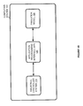
- FIG 2 is a flow diagram that illustrates an operation 200 of computing system 100 in an exemplary implementation.
- the operation 200 shown in Figure 2 may also be referred to as synchronization process 200 herein.
- the steps of operation 200 are indicated below parenthetically.
- the following discussion of synchronization process 200 will proceed with reference to computing system 100 of Figure 1B in order to illustrate its operations, but note that the details provided in Figure 1B are merely exemplary and not intended to limit the scope of synchronization process 200 to the specific implementation shown in Figure 1B .
- Synchronization process 200 may be employed to operate computing system 100 to facilitate simulating machines used in industrial automation.
- computing system 100 utilizes an application programming interface (API) 120 to apply timestamps to data exchanged between a simulation model created in a simulation application and an industrial controller system external to the simulation model (201).
- API application programming interface
- the industrial controller system 110 could comprise one or more physical industrial controller devices, emulated industrial controllers implemented in software, or any other control system - including combinations thereof.
- the simulation model 130 may typically comprise definitions for a virtual representation of at least a portion of a machine used in an industrial automation environment.
- the simulation model 130 could define the design and parameters of an entire robot, or could define an individual component of the robot, such as an arm joint, drive motor, articulation mechanism, or some other portion of the robot.
- the simulation model 130 could include information for rendering a three dimensional visualization of the machine, or at least a portion thereof.
- API 120 may facilitate data exchange between the simulation model 130 and the industrial controller system 110 in a bidirectional manner.
- the data transferred from the industrial controller system 110 to the simulation model 130 could comprise control signals used to drive the simulation
- the data received by the industrial controller system 110 from the simulation model 130 could comprise feedback, operational status, and other information associated with the execution of the simulation model 130.
- API 120 could be utilized to establish at least one communication link between the industrial controller system 110 and the simulation model 130 by linking ports associated with the industrial controller system 110 to the simulation model 130 to create an input and output interface between the industrial controller system 110 and the simulation model 130.
- Data may then be exchanged over the communication link between the industrial controller system 110 and the simulation model 130 by utilizing the input and output interface to transfer control program parameters, control signals, and other information between the industrial controller system 110 and the simulation model 130.
- the simulation model 130 may then utilize the data received from the industrial controller system 110 to generate an animated visualization of a machine being simulated.
- the data from the industrial controller system 110 could direct the simulation model 130 to move and animate a three dimensional visualization of the simulated machine in the same manner that the industrial controller system 110 could drive the physical machine itself.
- API 120 may be utilized to apply timestamps to any of the data exchanged between the industrial controller system 110 and the simulation model 130.
- API 120 could be utilized to apply a first timestamp to data as soon as it is transferred by the industrial controller system 110 for delivery to the simulation model 130, and to apply a second timestamp immediately before providing the data to the simulation model 130, and vice versa.
- Other techniques of utilizing API 120 to apply timestamps to data exchanged between the simulation model 130 and the industrial controller system 110 are contemplated and within the scope of this disclosure.
- the timestamps are then processed to synchronize the simulation model 130 and the industrial controller system 110 (202).
- the timestamps may be utilized to determine the timing of when to provide the data to the simulation model 130 or the industrial controller system 110 to achieve synchronization.
- processing the timestamps to synchronize the simulation model 130 and the industrial controller system 110 could comprise coordinating signal transmission intervals of the simulation model 130 and the industrial controller system 110 using the timestamps. Coordinating the signal transmission intervals between the simulation model 130 and the industrial controller system 110 is necessary in some examples because the signal transmission intervals could often comprise different rates.
- processing the timestamps to synchronize the simulation model 130 and the industrial controller system 110 could comprise providing a periodic clock pulse to the simulation model 130 and the industrial controller system 110 to advance the simulation model 130 and the industrial controller system 110 ahead one time step.
- the time step size for the simulation model 130 and the industrial controller system 110 could comprise different values, but would both be advanced by the appropriate amount responsive to the periodic clock pulse.
- each controller could have a different time step size, and each of these controllers could be further synchronized at each clock pulse by dynamically calculating the deltas for use in compensating for the differences in time step size between the multiple controllers.
- the API 120 may be utilized to apply timestamps to data exchanged between the simulation model 130 and the industrial controller system 110.
- the timestamps may then be processed in order to facilitate synchronization between the execution of the simulation model 130 and the industrial controller system 110.
- the simulation model 130 is able to receive and interpret control signals transmitted by the industrial controller system 110 at the appropriate timing to achieve smooth and harmonious operation of the simulation, thereby increasing the value and utility of the simulation model 130 through integration and synchronization with the industrial controller system 110.
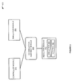
- FIG. 3 is a block diagram that illustrates an overview 300 of implementing controllers with simulated industrial devices.
- Overview 300 includes controller module 310, simulation module 320, co-simulation assembly module 330, and resulting module 340.
- Controller module 310 may be any physical or emulated controller configured to manage one or more devices in an industrial automation system.
- controller module 310 may be configured to provide control instructions that direct physical and/or simulated machines, or their individual components, to move or perform some action in three-dimensional space, such as controlling the motion of a robot arm.
- Simulation module 320 may be configured to generate a simulation model comprising simulation files that define various properties, parameters, and physical attributes of a real-world industrial device to ensure that the simulated device looks and operates in the same manner as the physical device from which it is modeled.
- the baseline controller is a physical hardware device in which a control program may be executed. A control program may then be loaded that is targeted to that specific controller hardware in order to retarget it to an emulation controller implemented in software.
- one workflow includes moving from physical to emulation control which allows for improved modeling versatility. Once in an emulation model, the emulation controller may interact with the simulation model. Another workflow considers a case in which the control program is fully designed in the emulation controller against the simulation. In this case, once the control program has been designed, it can be retargeted to the hardware controller. Notably, in both of the above transitions, the input/output (I/O) interface is preserved between the physical machine and the physical controller or the simulated machine and the emulation controller.
- I/O input/output
- a user, an engineer, or some other entity may generate a simulation within simulation module 320.
- Such a simulation may be used to model various industrial equipment, including robotic, fabrication, assembly, and other types of equipment.
- a user may further wish to control the simulation using an industrial controller from controller module 310.
- Controller module 310 as used herein is intended to represent a real, physical controller device or an emulated controller implemented in software that provides control instructions to the generated simulation. For example, if the simulation was used to emulate a robotic arm, one or more controllers could be used to manage and control the movement and articulation of the arm.
- co-simulation assembly module 330 can be used to format the controller and the simulation using a functional mock-up interface (FMI).
- FMI defines a standardized interface to be used in computer simulations to develop complex cyberphysical systems. These cyberphysical systems are represented in functional mock-up units (FMUs) that provide the functions necessary to generate the simulation.
- the functional mock-up units typically include an extensible markup language (XML) file comprising definitions of the variables used by the FMUs, equations used by the model, which may be defined as a set of functions, and other optional data, such as parameter tables, a user interface, and documentation which may be needed by the model, among other things.
- XML extensible markup language
- the FMI further includes information necessary to provide the control functions.
- necessary portions of the control functions are implemented in functional mock-up units to make the controls appear as simulation information within the FMI.
- the combination of the simulation functional mock-up units 344 and the control functional mock-up units 345 are used to provide resulting module 340.
- resulting module 340 could take the form of any other similar standardized interface for simulation.
- An emulation simulation interface environment is used to provide for this interface which is unique to each specific control system vendor. Translators may be provided throughout the emulation simulation interface from industrial control space to FMI space and vice versa.
- a user may control the simulation directly from the control functional mock-up units.
- the control functional mock-up units include all of the necessary functions to both receive a control instruction and execute that function.
- the control functional mock-up units may contain only the portion of information necessary to control the simulation.
- an external controller that receives input from the user may communicate with the control functional mock-up units using an application programming interface (API), such as API 120 as shown in Figure 1B .
- API application programming interface
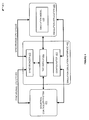
- Figure 4 is a block diagram that illustrates an operational scenario 400 involving a computing system in an exemplary implementation.
- the computing system executes emulation simulation interface 410 and may execute some or all of the operations of industrial controller system 420 and simulation application 430.
- the computing system could be a single device or could be distributed across many different systems and devices separated over diverse geographic areas.
- the emulation simulation interface 410 includes a configurator module 411, a tag server 412, and a synchronizer 413.
- the industrial controller system 420 comprises a virtual controller emulator, such as RSLogixTM Emulate 5000 provided by Rockwell Automation, Inc.
- the simulation application 430 could comprise any third-party simulation framework tool that complies with the FMI standard, but the MATLAB® SimulinkTM tool is used in this example.
- the simulation model 435 could comprise a .mdl file created in MATLAB® using library blocks for different systems.
- the emulation simulation interface 410 is used to connect controller tags to the simulation model 435 in MATLAB®. To connect the virtual controller output signals to the simulation model 435, it is necessary to establish an interface between the simulation model 435 and the industrial controller system 420. To this end, the emulation simulation interface 410 will set up an interface between input/output (I/O) signals of the controller 420 with the simulation model 435. The interface established by the emulation simulation interface 410 enables connectivity and data exchange in a bidirectional manner between the simulation model 435 and the controller 420.
- the emulation simulation interface 410 uses a virtual controller emulator such as RSLogixTM Emulate 5000 to encapsulate the control programs. The controller emulator mimics the operation of a ControlLogixTM programmable logic controller (PLC) but in software only.
- the virtual controller 420 transfers data to the simulation using output tags and receives data from the simulation using input tags.
- the configurator component 411 hosts the application-level information for connecting the virtual controller 420 with the simulation model 435.
- Tag server 412 coordinates the input and output tags for data exchange.
- tag server 412 provides distributed communication connectivity services for connecting the communicating parts in the controller side of the spectrum.
- the co-simulation master from FMI coordinates communication between the FMUs. Underneath the tag server service, the controllers and their respective communications are coordinated with simulations, which can become a very complex network of communicating units.
- the synchronizer 413 coordinates the clock progression between the controller 420 and the simulation model 435 to keep them synchronized.
- the clock synchronization is typically carried out in two phases. First, the co-simulation master coordinates global time among FMUs. Second, the tag server service 412 coordinates control level FMU time among the controllers. In situations where there is more than one control level FMU, time synchronization among them may be handled by the co-simulation master. An example of how the execution of a controller and a simulation may be synchronized at runtime will now be discussed with respect to Figure 5 .
- FIG. 5 is a block diagram that illustrates an operational scenario 500 for synchronizing a controller and a simulation in an exemplary implementation.
- Operational scenario 500 involves controller module 510, simulation module 530, and co-simulation master 540.
- Controller module 510 includes API 520.
- controller module 510 comprises a controller-side FMU and simulation module 530 comprises a simulation FMU.
- API 520 of controller module 510 generally reads and writes tags for data exchanged between the controller module 510 and the simulation module 530, and functions to synchronize the timing associated with this data exchange and execution of the simulation.
- the signal transmission intervals of the controller module 510 and the simulation model 530 may be exchanged at different time rates, and the co-simulation master 540 works in conjunction with API 520 to compensate for these different rates to achieve synchronization.
- controller module 510 is transferring control data to the simulation module 530.
- Co-simulation master 540 provides an interface to connect the controller module 510 FMU and the simulation module 530 FMU. As controller module 510 transfers the control data to simulation module 530, co-simulation master 540 utilizes API 520 to apply a first timestamp to the control data to mark the time in. Co-simulation master 540 then provides the control data to simulation module 530 and a second timestamp is applied to the data to mark the time out.
- co-simulation master 540 is aware of what time the controller module 510 intended to provide the control data to the simulation module 530 based on the first timestamp noting the time in, and what time the simulation module 530 actually receives the control data based on the second timestamp noting the time out.
- co-simulation master 540 calculates time offsets for the control data based on the timestamps to compensate for delay and other timing anomalies. The co-simulation master 540 then advances the master clock one clock cycle and sends a clock pulse to both the controller module 510 and the simulation module 530 to advance each module ahead one time step. Note that the time step size may not be the same size for the simulation module 530 and the controller module 510.
- the FMUs of both the simulation module 530 and the controller module 510 are configured to emit periodic pulses, such as every twenty milliseconds, into the simulation and controller, respectively, to advance in time at the appropriate time step sizes, since as noted above, the time step sizes may not be the same size for the simulation module 530 and the controller module 510.
- the controller module 510 includes multiple controllers, each of the controllers in the controller module 510 could be operating at different time step sizes. An example of how multiple controllers that operate at different time step sizes could be synchronized will now be discussed in greater detail with respect to Figure 6 .
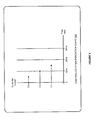
- Figure 6 is a controller synchronization chart 600 that illustrates an exemplary technique of synchronizing multiple controllers.
- the multiple controllers could comprise several separate physical controller devices, multiple independent emulated controllers implemented in software, or combinations thereof.
- multiple controllers could be used to control several separate components of a single machine being simulated, such as various drive motors, articulation mechanisms, and other parts of the machine.
- the controllers are numbered C1, C2, and C3.
- the time step size in this example is ten milliseconds, as shown along the horizontal x-axis of controller synchronization chart 600.
- controller C1 has advanced fifteen milliseconds
- C2 has advanced ten milliseconds
- C3 has advanced five milliseconds.
- controller C1 has advanced fifteen milliseconds
- C2 has advanced ten milliseconds
- C3 has advanced five milliseconds.
- controller C1 the time offset is calculated to be a plus five millisecond delta from the time step size, since C1 advanced fifteen milliseconds but the time step size is only ten milliseconds.
- the next time step for controller C1 is then calculated by subtracting the delta from the time step size, so with a time step size of ten milliseconds minus a plus five millisecond delta, C1 should only advance five milliseconds on the next time step to achieve synchronization with the other controllers and the ten millisecond time step size.
- Controller C2 has a time step size of ten milliseconds, which matches the time step size of the simulation. Thus, no offset needs to be calculated and no compensation of the time step size of controller C2 is necessary for synchronization.
- Controller C3 has a time step size of only five milliseconds, so the time offset is calculated to be a negative five millisecond delta from the time step size of ten milliseconds.
- the next time step for controller C3 is then calculated by subtracting the delta from the time step size, so with a time step size of ten milliseconds minus a negative five millisecond delta, C1 should advance fifteen milliseconds on the next time step to achieve synchronization with the other controllers and the overall ten millisecond time step size.
- the offsets for each of the controllers C1, C2, and C3 are then continually recalculated dynamically at each time step to ensure synchronization persists. In this manner, the simulation model proceeds to learn the amplitude and frequency of the sinusoidal time progression of each of the controllers C1, C2, and C3.
- FIG. 7 is a block diagram that illustrates an operational scenario 700 involving a computing system in an exemplary implementation.
- Operational scenario 700 is capable of creating and operating a machine simulation in an industrial automation environment.
- the system architecture may consist generally of five main parts: control program design 710, industrial controller system 720, simulation modeling 730, computer-aided design (CAD) solid modeling 740, and visualization 750.
- CAD computer-aided design
- Various industry-based tools and open source software may be used to implement these design goals.
- control programming design 710 may be carried out using a control programming tool, such as the Studio5000TM programming tool by Rockwell Automation, Inc.
- Control program execution is handled by industrial controller system 720, which could comprise an emulated virtual controller implemented in software, such as RSLogixTM Emulate 5000 by Rockwell Automation, Inc.
- Simulation modeling 730 can be performed by any simulation framework tool, such as the MATLAB® SimulinkTM tool.
- Solid modeling 740 may be handled by any CAD software, such as SolidworksTM or the like.
- visualization 550 may be performed by any suitable visualization tool, such as a Scalable Vector Graphics (SVG) tool, Virtual Reality Modeling Language (VRML) tool, and others.
- SVG Scalable Vector Graphics
- VRML Virtual Reality Modeling Language
- FIG. 7 an example information flow of the integrated system is shown.
- the solid modeling phase 740 produces a three dimensional representation of the mechanical system to be controlled.
- the solid model may be converted into two information elements: a kinematics simulation and a graphical assembly.
- the SolidworksTM tool provides plugins to generate both data files as MATLAB® simulation and VRML export files.
- the Studio5000TM tool by Rockwell Automation is an industrial control programming design tool 710 that is used to create control algorithms written in an International Electrotechnical Commission (IEC) 61131-based programming language.
- the control program is deployed in the virtual controller within industrial controller system 720.
- the kinematics simulation is downloaded to the MATLAB® tool for simulating the machine under specific load conditions.
- the simulation model 730 interacts with the controller 720 at runtime to stimulate the controlling algorithms with the responses of the machine that is put under stress with dynamic loading and control profiles.
- Graphical assemblies will be further processed to become a hierarchical data structure of graphical description that can be animated in the visualization tool 750.
- the visualization tool collects the real-time data that is generated in the controller-to-simulation interaction.
- control program parameters are transferred between the simulation model 730 and the controller 720 using an I/O interface.
- MATLAB® provides a SimMechanicsLinks plugin for CAD software SolidworksTM to transfer the CAD model produced in the solid modeling phase 740 into the simulation model 730.
- the simulation model 730 contains mass and inertial properties of each of the component parts of a machine described in the CAD drawings. This information is essential to generate accurate animation of the mechanical system.
- Kinematics and dynamical information of the simulation model 530 can be used to generate realistic model conditions since the actual physical properties of the model are included in the simulation calculations.
- visualization 550 may be performed by any suitable visualization tool, such as a Scalable Vector Graphics (SVG) tool, Virtual Reality Modeling Language (VRML) tool, or any other simulation modeling tool,
- a high quality and realistic animation can be produced in any VRML-compatible tool using the exported VRML models.
- VRML provides an open source, platform-independent graphical language to create and view three dimensional models.
- VRML is a text-based language so it can be easily edited using any text editor. To bring the VRML tool into this workflow, it is necessary to attach an API to it so it can communicate with the other parts of the system.
- other tools besides VRML may be utilized for this purpose and are within the scope of this disclosure.
- Robots are widely used in industrial automation applications and their control algorithms are developed by system engineers.
- a six-axis articulated robot model may be used.
- a desired motion profile for the robot's end effector position is established in the controlling program 710 using command position profiles.
- the command positions are points of desired motion trajectory for the end effector.
- different parts (links) of the robot must be placed in a position by the driving motors at the link joints.
- These motors are driven by torque signals that are to be calculated by the controlling drivers.
- the controlling torque depends on knowledge of the system response to the torque and the load at the end effector. In the classical design approach, these pieces of information are known by trial and error or by experienced designers.
- the intent here is to capture the information flow for automating the process of generating the feedback information for the drivers and controllers. Based on the drivers' torque signal, each joint will move and the end effector will move in the space to a target location. Current position is the feedback to the drivers and controllers for close loop control.
- a work flow, validation framework, and process to enable a virtual design engineering environment have been presented.
- the environment enables interoperability of solid model design, controllers, simulation, and visualization tools into an integrated development environment. Results showed that the selected work flow and information exchange could be assembled in an automated system.
- the deployment of the virtual design engineering environment permitted observing in real-time the effect of the controlling algorithm on the machine prototype which was simulated and controlled by motion instructions.
- This disclosure enables early validation of controlling logic for complex industrial automation projects and manufacturing plants.
- the benefits include the reduction of engineering cost, time, and resources during the design and prototyping of industrial automation machinery.
- the virtual design engineering environment opens new opportunities to train engineers and operators in controlling machines, without the need for the physical presence of the actual machine.
- design phase runtime the industrial control device can be real or emulated. Either encapsulation is connected to the simulation.
- commissioned phase runtime the industrial control device and the simulation execute in parallel with a real controller.
- another benefit of the system is to aid system engineers to create optimized industrial control programs. For example, the Studio5000TM tool by Rockwell Automation allows for online editing of the control program, and the design may be incrementally improved in virtual design.
- FIG. 8 is a block diagram that illustrates computing system 800 in an exemplary implementation.
- Computing system 800 provides an example of computing system 100 or any system that may be used to facilitate simulating machines used in industrial automation, although other systems capable of performing the techniques disclosed herein could use alternative configurations, including computing system 100.
- Computing system 800 is representative of a computing system that may be employed in any computing apparatus, system, or device, or collections thereof.
- computing system 800 may be employed in server computers, cloud computing platforms, data centers, any physical or virtual computing machine, and any variation or combination thereof.
- computing system 800 may be employed in desktop computers, laptop computers, tablets, smartphones, or the like.
- Computing system 800 includes processing system 801, storage system 803, software 805, communication interface 807, and user interface 809.
- Processing system 801 is operatively coupled with storage system 803, communication interface 807, and user interface 809.
- Processing system 801 loads and executes software 805 from storage system 803.
- Software 805 includes application 806 which itself includes synchronization process 200. Synchronization process 200 may optionally be implemented separately from application 806.
- software 805 directs computing system 800 to operate as described herein for synchronization process 200 or variations thereof.
- Computing system 800 may optionally include additional devices, features, or functionality not discussed here for purposes of brevity.
- Computing system 800 may be representative of any computing apparatus, system, or systems on which application 806 and synchronization process 200 or variations thereof may be suitably implemented.
- Examples of computing system 800 include mobile computing devices, such as cell phones, tablet computers, laptop computers, notebook computers, and gaming devices, as well as any other type of mobile computing devices and any combination or variation thereof. Note that the features and functionality of computing system 800 may apply as well to desktop computers, server computers, and virtual machines, as well as any other type of computing system, variation, or combination thereof.
- processing system 801 may comprise a microprocessor and other circuitry that retrieves and executes software 805 from storage system 803.
- Processing system 801 may be implemented within a single processing device but may also be distributed across multiple processing devices or sub-systems that cooperate in executing program instructions. Examples of processing system 801 include general purpose central processing units, application specific processors, and logic devices, as well as any other type of processing device, combinations, or variations thereof.
- Storage system 803 may comprise any non-transitory computer-readable media or storage media readable by processing system 801 and capable of storing software 805, such as a disk drive, flash drive, data storage circuitry, or some other hardware memory apparatus.
- a computer apparatus could comprise storage system 803 and operating software 805.
- Storage system 803 may include volatile and nonvolatile, removable and non-removable media implemented in any method or technology for storage of information, such as computer readable instructions, data structures, program modules, or other data.
- Storage system 803 may be implemented as a single storage device but may also be implemented across multiple storage devices or sub-systems co-located or distributed relative to each other - including devices in different geographic areas. Storage system 803 may also be embedded in various types of equipment.
- Storage system 803 may comprise additional elements, such as a controller, capable of communicating with processing system 801.
- storage media include random access memory, read only memory, magnetic disks, optical disks, flash memory, virtual memory and non-virtual memory, magnetic cassettes, magnetic tape, magnetic disk storage or other magnetic storage devices, or any other medium which can be used to store the desired information and that may be accessed by an instruction execution system, as well as any combination or variation thereof, or any other type of storage media.
- the storage media a propagated signal.
- processing system 801 loads and executes portions of software 805, such as synchronization process 200, in order to operate as described herein.
- software 805 may be implemented in program instructions and among other functions may, when executed by computing system 800 in general or processing system 801 in particular, direct computing system 800 or processing system 801 to utilize an application programming interface (API) to apply timestamps to data exchanged between a simulation model created in a simulation application and an industrial controller system external to the simulation model, and process the timestamps to synchronize the simulation model and the industrial controller system.
- Software 805 may include additional processes, programs, or components, such as operating system software or other application software. Examples of operating systems include Windows®, iOS®, and Android®, as well as any other suitable operating system.
- Software 805 may also comprise firmware or some other form of machine-readable processing instructions executable by processing system 801.
- software 805 may, when loaded into processing system 801 and executed, transform computing system 800 overall from a general-purpose computing system into a special-purpose computing system customized to facilitate simulating machines used in industrial automation as described herein for each implementation.
- Software 805 may also transform the physical structure of storage system 803. The specific transformation of the physical structure may depend on various factors in different implementations of this description. Examples of such factors may include, but are not limited to, the technology used to implement the storage media of storage system 803, whether the computer-storage media are characterized as primary or secondary storage, and the like. For example, if the computer-storage media are implemented as semiconductor-based memory, software 805 may transform the physical state of the semiconductor memory when the software is encoded therein.
- software 805 may transform the state of transistors, capacitors, or other discrete circuit elements constituting the semiconductor memory. A similar transformation may occur with respect to magnetic or optical media. Other transformations of physical media are possible without departing from the scope of the present description, with the foregoing examples provided only to facilitate this discussion.
- Communication interface 807 may include communication connections and devices that allow for communication between computing system 800 and other computing systems (not shown) or services, over a communication network or collection of networks. Examples of connections and devices that together allow for inter-system communication may include network interface cards, antennas, power amplifiers, RF circuitry, transceivers, and other communication circuitry. The aforementioned network, connections, and devices are well known and need not be discussed at length here.
- User interface 809 may include a voice input device, a touch input device for receiving a gesture from a user, a motion input device for detecting non-touch gestures and other motions by a user, and other comparable input devices and associated processing elements capable of receiving user input from a user.
- Output devices such as a display system, speakers, haptic devices, and other types of output devices may also be included in user interface 809.
- the aforementioned user input devices are well known in the art and need not be discussed at length here.
- User interface 809 may also include associated user interface software executable by processing system 801 in support of the various user input and output devices discussed above. Separately or in conjunction with each other and other hardware and software elements, the user interface software and devices may provide a graphical user interface, a natural user interface, or any other kind of user interface.
Landscapes
- Engineering & Computer Science (AREA)
- Physics & Mathematics (AREA)
- General Physics & Mathematics (AREA)
- Theoretical Computer Science (AREA)
- Automation & Control Theory (AREA)
- General Engineering & Computer Science (AREA)
- Manufacturing & Machinery (AREA)
- Software Systems (AREA)
- Geometry (AREA)
- Evolutionary Computation (AREA)
- Computer Hardware Design (AREA)
- Quality & Reliability (AREA)
- Signal Processing (AREA)
- Computer Networks & Wireless Communication (AREA)
- Debugging And Monitoring (AREA)
- Management, Administration, Business Operations System, And Electronic Commerce (AREA)
- Numerical Control (AREA)
Applications Claiming Priority (2)
| Application Number | Priority Date | Filing Date | Title |
|---|---|---|---|
| US201361901956P | 2013-11-08 | 2013-11-08 | |
| US14/303,172 US10755003B2 (en) | 2013-11-08 | 2014-06-12 | Time synchronization of signal transmission intervals for simulating a machine in industrial automation |
Publications (3)
| Publication Number | Publication Date |
|---|---|
| EP2871540A2 true EP2871540A2 (de) | 2015-05-13 |
| EP2871540A3 EP2871540A3 (de) | 2016-07-13 |
| EP2871540B1 EP2871540B1 (de) | 2020-04-08 |
Family
ID=51868857
Family Applications (1)
| Application Number | Title | Priority Date | Filing Date |
|---|---|---|---|
| EP14192221.1A Active EP2871540B1 (de) | 2013-11-08 | 2014-11-07 | Zeitsynchronisation von Signalübertragungsintervallen zur Simulation einer Maschine in der industriellen Automatisierung |
Country Status (3)
| Country | Link |
|---|---|
| US (1) | US10755003B2 (de) |
| EP (1) | EP2871540B1 (de) |
| CN (1) | CN104678778B (de) |
Cited By (10)
| Publication number | Priority date | Publication date | Assignee | Title |
|---|---|---|---|---|
| WO2018054465A1 (de) * | 2016-09-22 | 2018-03-29 | Siemens Aktiengesellschaft | Verfahren und vorrichtungen zur synchronisierten simulation und emulation von automatisierten produktionsanlagen |
| IT201700045152A1 (it) * | 2017-04-26 | 2018-10-26 | Nuovo Pignone Tecnologie Srl | Metodo e sistema per operazioni di modellazione di un impianto fisico |
| WO2020007468A1 (en) * | 2018-07-05 | 2020-01-09 | Siemens Aktiengesellschaft | A method for synchronizing programs for simulation of a technical system |
| CN112784328A (zh) * | 2019-11-11 | 2021-05-11 | 罗克韦尔自动化技术公司 | 用于开发自动化系统模型的系统和方法 |
| EP3819091A1 (de) * | 2019-11-11 | 2021-05-12 | Rockwell Automation Technologies, Inc. | Robotische digitale zwillingssteuerung mit industrieller kontextsimulation |
| EP3974928A1 (de) * | 2020-09-28 | 2022-03-30 | Rockwell Automation Technologies, Inc. | Schaltplanmanager und emulator |
| US11526159B2 (en) | 2020-02-14 | 2022-12-13 | Rockwell Automation Technologies, Inc. | Augmented reality human machine interface testing |
| US11675936B2 (en) | 2020-09-28 | 2023-06-13 | Rockwell Automation Technologies, Inc. | Unifying multiple simulation models |
| US20240385903A1 (en) * | 2023-05-15 | 2024-11-21 | Honeywell International Inc. | Methods, apparatuses, and computer program products for enabling dynamic external access to a process simulation service |
| CN121562096A (zh) * | 2026-01-26 | 2026-02-24 | 中南大学 | 一种基于fmi标准的气动连杆机构协同仿真方法、电子设备及存储介质 |
Families Citing this family (29)
| Publication number | Priority date | Publication date | Assignee | Title |
|---|---|---|---|---|
| US20140156234A1 (en) * | 2012-12-03 | 2014-06-05 | Rockwell Automation Technologies, Inc., | Input output cloning for industrial automation |
| US20160275219A1 (en) * | 2015-03-20 | 2016-09-22 | Siemens Product Lifecycle Management Software Inc. | Simulating an industrial system |
| US11222551B2 (en) * | 2015-07-23 | 2022-01-11 | Rockwell Automation Technologies, Inc. | Snapshot management architecture for process control operator training system lifecycle |
| JP6496278B2 (ja) * | 2016-06-27 | 2019-04-03 | ファナック株式会社 | シミュレーションシステム |
| CN109890474B (zh) | 2016-09-01 | 2023-04-04 | 雷蛇(亚太)私人有限公司 | 用于仿真虚拟控制器装置的方法、仿真器及计算机可读介质 |
| US10678216B2 (en) | 2017-02-28 | 2020-06-09 | Sap Se | Manufacturing process data collection and analytics |
| US10353379B2 (en) | 2017-02-28 | 2019-07-16 | Sap Se | Manufacturing process data collection and analytics |
| CN107479983B (zh) * | 2017-07-11 | 2021-04-20 | 核动力运行研究所 | 基于时域控制技术的变步长多程序同步计算系统及方法 |
| EP3557453B1 (de) * | 2017-08-29 | 2023-05-03 | Siemens Aktiengesellschaft | Verfahren und vorrichtung zur bestimmung einer datenleseperiode |
| EP3521949B1 (de) * | 2018-02-01 | 2021-01-13 | Siemens Aktiengesellschaft | Vorrichtung zum simulieren einer gesteuerten maschine oder anlage sowie verfahren |
| US10628204B2 (en) | 2018-02-27 | 2020-04-21 | Performance Software Corporation | Virtual communication router with time-quantum synchronization |
| EP3579126A1 (de) * | 2018-06-07 | 2019-12-11 | Kompetenzzentrum - Das virtuelle Fahrzeug Forschungsgesellschaft mbH | Verfahren und vorrichtung zur co-simulation |
| WO2020089664A1 (en) | 2018-10-29 | 2020-05-07 | Siemens Industry Software Ltd. | A method and a system for synchronizing a first and a second simulation system |
| EP3650970B8 (de) * | 2018-11-09 | 2022-02-09 | Siemens Aktiengesellschaft | Verfahren und vorrichtung zum computergestützten simulieren eines modularen technischen systems |
| EP3693816A1 (de) | 2019-02-11 | 2020-08-12 | Siemens Aktiengesellschaft | System zur validierung eines steuerungsprogramms |
| EP3715982A1 (de) * | 2019-03-27 | 2020-09-30 | Siemens Aktiengesellschaft | Virtueller sensor auf einer übergeordneten maschinenplattform |
| EP3812985A1 (de) * | 2019-10-22 | 2021-04-28 | Siemens Aktiengesellschaft | Automatisierungskomponente und verfahren zu deren betrieb auf der basis eines erweiterten informationsmodells |
| CN111159909B (zh) * | 2019-12-31 | 2023-05-16 | 中国船舶重工集团公司第七0三研究所 | 一种压气机特性数据处理及特性云图绘制方法 |
| CN112367202B (zh) * | 2020-11-10 | 2022-11-18 | 西安热工研究院有限公司 | 物理实体控制系统与虚拟仿真生产环境的数据交换方法 |
| US20220156433A1 (en) * | 2020-11-13 | 2022-05-19 | Rockwell Automation Technologies, Inc. | Industrial network communication emulation |
| CN112733352B (zh) * | 2020-12-31 | 2023-12-08 | 芯和半导体科技(上海)股份有限公司 | 一种布局前高速串行信号通道仿真的创新方法 |
| CN113110114B (zh) * | 2021-05-24 | 2023-07-14 | 北京润科通用技术有限公司 | 一种超实时联合仿真的调度方法及装置 |
| CN115769213A (zh) * | 2021-06-18 | 2023-03-07 | 华为技术有限公司 | 协同仿真的方法及装置 |
| KR20230074969A (ko) * | 2021-11-22 | 2023-05-31 | 주식회사 엘지에너지솔루션 | 이차전지 생산을 위한 코터 시뮬레이션 테스트 방법 및 장치 |
| US11835942B2 (en) * | 2021-11-23 | 2023-12-05 | Rockwell Automation Technologies, Inc. | Real-time high-speed clock signal for industrial network emulation |
| CN114442506A (zh) * | 2021-12-06 | 2022-05-06 | 埃夫特智能装备股份有限公司 | 一种基于虚拟机器人控制器仿真调试平台及其调试方法 |
| CN116300557B (zh) * | 2022-12-05 | 2026-04-03 | 上海励驰半导体有限公司 | 多系统交互控制方法、装置、电子设备、存储介质 |
| EP4475030A1 (de) * | 2023-06-07 | 2024-12-11 | Siemens Industry Software NV | Verfahren und system zur co-simulation mittels functional mockup interface for model exchange |
| CN119416547B (zh) * | 2025-01-09 | 2025-10-14 | 凯云联创(北京)科技有限公司 | 仿真系统中功能单元模型的校验方法及装置 |
Family Cites Families (51)
| Publication number | Priority date | Publication date | Assignee | Title |
|---|---|---|---|---|
| US5485620A (en) * | 1994-02-25 | 1996-01-16 | Automation System And Products, Inc. | Integrated control system for industrial automation applications |
| DE19500057C1 (de) * | 1995-01-03 | 1996-02-29 | Starck H C Gmbh Co Kg | Verfahren zur Herstellung von reinen Wolframat- und/oder Molybdat-Lösungen |
| JP3916727B2 (ja) | 1997-05-30 | 2007-05-23 | 新日鉄ソリューションズ株式会社 | シミュレーション装置およびその方法、コンピュータ読み取り可能な記録媒体 |
| US6944584B1 (en) | 1999-04-16 | 2005-09-13 | Brooks Automation, Inc. | System and method for control and simulation |
| US7649925B2 (en) * | 1999-06-14 | 2010-01-19 | Time Domain Corporation | Time transfer utilizing ultra wideband signals |
| US6477435B1 (en) | 1999-09-24 | 2002-11-05 | Rockwell Software Inc. | Automated programming system for industrial control using area-model |
| US6535926B1 (en) * | 1999-09-30 | 2003-03-18 | Rockwell Automation Technologies, Inc. | Time synchronization system for industrial control network using global reference pulses |
| US7054399B1 (en) | 2000-09-29 | 2006-05-30 | Rockwell Automation Technologies, Inc. | Low overhead synchronized activation of functional modules |
| US7818457B1 (en) * | 2001-05-22 | 2010-10-19 | Rockwell Automation Technologies, Inc. | Apparatus for multi-chassis configurable time synchronization |
| US6788218B2 (en) | 2001-07-19 | 2004-09-07 | Lancer Partnership, Ltd. | Pseudo real-time diagnostic and process monitoring system |
| US9565275B2 (en) * | 2012-02-09 | 2017-02-07 | Rockwell Automation Technologies, Inc. | Transformation of industrial data into useful cloud information |
| US7392165B2 (en) | 2002-10-21 | 2008-06-24 | Fisher-Rosemount Systems, Inc. | Simulation system for multi-node process control systems |
| US7467018B1 (en) | 2002-11-18 | 2008-12-16 | Rockwell Automation Technologies, Inc. | Embedded database systems and methods in an industrial controller environment |
| US7835893B2 (en) * | 2003-04-30 | 2010-11-16 | Landmark Graphics Corporation | Method and system for scenario and case decision management |
| US7778814B2 (en) * | 2004-03-30 | 2010-08-17 | Siemens Aktiengesellschaft | Method and device for simulating an automation system |
| US7565609B2 (en) * | 2004-07-16 | 2009-07-21 | National Instruments Corporation | Synchronizing execution of graphical programs executing on different computer systems |
| US7991602B2 (en) * | 2005-01-27 | 2011-08-02 | Rockwell Automation Technologies, Inc. | Agent simulation development environment |
| US20070067458A1 (en) | 2005-09-20 | 2007-03-22 | Rockwell Software, Inc. | Proxy server for integration of industrial automation data over multiple networks |
| US7447931B1 (en) * | 2005-12-09 | 2008-11-04 | Rockwell Automation Technologies, Inc. | Step time change compensation in an industrial automation network |
| US8019583B1 (en) * | 2006-06-08 | 2011-09-13 | Rockwell Automation Technologies, Inc. | Selective functional group simulation of automation control and information systems |
| US7676279B2 (en) | 2006-09-29 | 2010-03-09 | Rockwell Automation Technologies, Inc. | Services for industrial control systems |
| JP2008165399A (ja) | 2006-12-27 | 2008-07-17 | Fanuc Ltd | シミュレーションデータ作成支援装置 |
| US20080168092A1 (en) * | 2007-01-10 | 2008-07-10 | General Electric Company | Systems and methods for turbine control simulation |
| US7936790B2 (en) * | 2007-08-30 | 2011-05-03 | Silicon Image, Inc. | Synchronizing related data streams in interconnection networks |
| US7809656B2 (en) | 2007-09-27 | 2010-10-05 | Rockwell Automation Technologies, Inc. | Microhistorians as proxies for data transfer |
| US7801710B2 (en) | 2007-09-28 | 2010-09-21 | Rockwell Automation Technologies, Inc. | Simulation controls for model variability and randomness |
| US20090089031A1 (en) | 2007-09-28 | 2009-04-02 | Rockwell Automation Technologies, Inc. | Integrated simulation of controllers and devices |
| US8069021B2 (en) * | 2007-09-28 | 2011-11-29 | Rockwell Automation Technologies, Inc. | Distributed simulation and synchronization |
| US8239158B2 (en) * | 2008-08-04 | 2012-08-07 | National Instruments Corporation | Synchronizing a loop performed by a measurement device with a measurement and control loop performed by a processor of a host computer |
| CN101729180A (zh) * | 2008-10-21 | 2010-06-09 | 华为技术有限公司 | 精准时钟同步方法及系统、精准时钟频率/时间同步装置 |
| FR2950449A1 (fr) | 2009-09-23 | 2011-03-25 | Eurocopter France | Simulation en temps reel hautement representative d'un systeme avionique |
| US8571068B2 (en) * | 2010-01-05 | 2013-10-29 | Futurewei Technologies, Inc. | Network timing distribution and synchronization using virtual network delays |
| CA3074776C (en) * | 2010-07-23 | 2021-02-16 | Saudi Arabian Oil Company | Machines, computer program products, and computer-implemented methods providing an integrated node for data acquisition and control |
| US8909509B2 (en) | 2010-10-01 | 2014-12-09 | Rockwell Automation Technologies, Inc. | Dynamically selecting master clock to manage non-linear simulation clocks |
| US8694296B2 (en) | 2010-10-22 | 2014-04-08 | Agile Planet, Inc. | Method and apparatus for integrated simulation |
| US8756041B2 (en) | 2011-03-07 | 2014-06-17 | Rockwell Automation Technologies, Inc. | Industrial simulation using redirected I/O module configurations |
| US20120239374A1 (en) | 2011-03-18 | 2012-09-20 | General Electric Company | System and method of simulating input/output modules in a control system |
| US9220066B2 (en) * | 2011-06-20 | 2015-12-22 | At&T Intellectual Property I, L.P. | Bundling data transfers and employing tail optimization protocol to manage cellular radio resource utilization |
| CN102298334B (zh) * | 2011-08-31 | 2013-03-13 | 北京空间飞行器总体设计部 | 用于地面仿真系统的断点仿真控制器及控制方法 |
| US9285800B2 (en) | 2011-11-11 | 2016-03-15 | Rockwell Automation Technologies, Inc | Systems and methods for asynchronous searching and filtering of data |
| US9529348B2 (en) * | 2012-01-24 | 2016-12-27 | Emerson Process Management Power & Water Solutions, Inc. | Method and apparatus for deploying industrial plant simulators using cloud computing technologies |
| US9223754B2 (en) * | 2012-06-29 | 2015-12-29 | Dassault Systèmes, S.A. | Co-simulation procedures using full derivatives of output variables |
| US9253054B2 (en) | 2012-08-09 | 2016-02-02 | Rockwell Automation Technologies, Inc. | Remote industrial monitoring and analytics using a cloud infrastructure |
| US9052708B2 (en) | 2012-09-05 | 2015-06-09 | General Electric Company | Systems and methods for improved device commissioning and decommissioning |
| US20140088927A1 (en) | 2012-09-27 | 2014-03-27 | Siemens Product Lifecycle Management Software Inc. | Systems and methods for simulation of virtual model |
| US9310832B2 (en) * | 2012-10-30 | 2016-04-12 | National Instruments Corporation | Backplane clock synchronization |
| US9244452B2 (en) | 2012-11-02 | 2016-01-26 | Rockwell Automation Technologies, Inc. | Configuration and monitoring via design diagram representation |
| US20140156234A1 (en) | 2012-12-03 | 2014-06-05 | Rockwell Automation Technologies, Inc., | Input output cloning for industrial automation |
| US8769448B1 (en) | 2013-01-23 | 2014-07-01 | Xilinx, Inc. | Circuit design simulation |
| EP2897011B1 (de) | 2014-01-21 | 2019-08-21 | Siemens Aktiengesellschaft | Verfahren und Simulationsanordnung zur Simulation einer automatisierten Industrieanlage |
| US20160349967A1 (en) | 2015-05-28 | 2016-12-01 | Rockwell Automation Technologies, Inc. | Offline investigation in an industrial automation environment |
-
2014
- 2014-06-12 US US14/303,172 patent/US10755003B2/en active Active
- 2014-11-07 EP EP14192221.1A patent/EP2871540B1/de active Active
- 2014-11-10 CN CN201410645439.XA patent/CN104678778B/zh not_active Expired - Fee Related
Non-Patent Citations (1)
| Title |
|---|
| None |
Cited By (20)
| Publication number | Priority date | Publication date | Assignee | Title |
|---|---|---|---|---|
| WO2018054465A1 (de) * | 2016-09-22 | 2018-03-29 | Siemens Aktiengesellschaft | Verfahren und vorrichtungen zur synchronisierten simulation und emulation von automatisierten produktionsanlagen |
| US12025975B2 (en) | 2017-04-26 | 2024-07-02 | Ge Infrastructure Technology Llc | Method and system for modeling operations of a physical plant |
| IT201700045152A1 (it) * | 2017-04-26 | 2018-10-26 | Nuovo Pignone Tecnologie Srl | Metodo e sistema per operazioni di modellazione di un impianto fisico |
| WO2018197308A1 (en) * | 2017-04-26 | 2018-11-01 | Nuovo Pignone Tecnologie Srl | Method and system for modeling operations of a physical plant |
| KR20190134799A (ko) | 2017-04-26 | 2019-12-04 | 누보 피그노네 테크놀로지 에스알엘 | 물리적 플랜트의 모델링 운영을 위한 방법 및 시스템 |
| WO2020007468A1 (en) * | 2018-07-05 | 2020-01-09 | Siemens Aktiengesellschaft | A method for synchronizing programs for simulation of a technical system |
| CN112784328A (zh) * | 2019-11-11 | 2021-05-11 | 罗克韦尔自动化技术公司 | 用于开发自动化系统模型的系统和方法 |
| CN112784328B (zh) * | 2019-11-11 | 2024-04-26 | 罗克韦尔自动化技术公司 | 用于开发自动化系统模型的系统和方法 |
| US12061845B2 (en) | 2019-11-11 | 2024-08-13 | Rockwell Automation Technologies, Inc. | Creation of a digital twin from a mechanical model |
| US11318616B2 (en) | 2019-11-11 | 2022-05-03 | Rockwell Automation Technologies, Inc. | Robotic digital twin control with industrial context simulation |
| EP3819091A1 (de) * | 2019-11-11 | 2021-05-12 | Rockwell Automation Technologies, Inc. | Robotische digitale zwillingssteuerung mit industrieller kontextsimulation |
| US11638994B2 (en) | 2019-11-11 | 2023-05-02 | Rockwell Automation Technologies, Inc. | Robotic digital twin control with industrial context simulation |
| EP3819733A1 (de) * | 2019-11-11 | 2021-05-12 | Rockwell Automation Technologies, Inc. | Erzeugung eines digitalen zwillings aus einem mechanischen modell |
| US11526159B2 (en) | 2020-02-14 | 2022-12-13 | Rockwell Automation Technologies, Inc. | Augmented reality human machine interface testing |
| US11782427B2 (en) | 2020-02-14 | 2023-10-10 | Rockwell Automation Technologies, Inc. | Augmented reality human machine interface testing |
| US11675936B2 (en) | 2020-09-28 | 2023-06-13 | Rockwell Automation Technologies, Inc. | Unifying multiple simulation models |
| EP3974928A1 (de) * | 2020-09-28 | 2022-03-30 | Rockwell Automation Technologies, Inc. | Schaltplanmanager und emulator |
| US20240385903A1 (en) * | 2023-05-15 | 2024-11-21 | Honeywell International Inc. | Methods, apparatuses, and computer program products for enabling dynamic external access to a process simulation service |
| US12498992B2 (en) * | 2023-05-15 | 2025-12-16 | Honeywell International Inc. | Methods, apparatuses, and computer program products for enabling dynamic external access to a process simulation service |
| CN121562096A (zh) * | 2026-01-26 | 2026-02-24 | 中南大学 | 一种基于fmi标准的气动连杆机构协同仿真方法、电子设备及存储介质 |
Also Published As
| Publication number | Publication date |
|---|---|
| CN104678778A (zh) | 2015-06-03 |
| CN104678778B (zh) | 2018-06-08 |
| EP2871540A3 (de) | 2016-07-13 |
| US10755003B2 (en) | 2020-08-25 |
| EP2871540B1 (de) | 2020-04-08 |
| US20150134313A1 (en) | 2015-05-14 |
Similar Documents
| Publication | Publication Date | Title |
|---|---|---|
| US10755003B2 (en) | Time synchronization of signal transmission intervals for simulating a machine in industrial automation | |
| EP2871544B1 (de) | Schnittstelle zum Datenaustausch zwischen industriellen Steuerungen und Simulationsanwendungen zur Simulation einer Maschine | |
| EP3002646B1 (de) | Virtuelle designentwicklung | |
| US11638994B2 (en) | Robotic digital twin control with industrial context simulation | |
| Leng et al. | Digital twins-based remote semi-physical commissioning of flow-type smart manufacturing systems | |
| US10782668B2 (en) | Development of control applications in augmented reality environment | |
| US20140180644A1 (en) | Integration of simulation of a machine for industrial automation | |
| EP4002189A1 (de) | Emulation einer industriellen netzwerkkommunikation | |
| EP3819733A1 (de) | Erzeugung eines digitalen zwillings aus einem mechanischen modell | |
| Kadir et al. | Towards high-fidelity machining simulation | |
| US11675936B2 (en) | Unifying multiple simulation models | |
| Vergnano et al. | Interactive simulation-based-training tools for manufacturing systems operators: an industrial case study | |
| EP3037904B1 (de) | Dimensionierung und auswahl näher an der ausführungsumgebung | |
| CN104777758A (zh) | 一种微小卫星设备通用模拟器 | |
| Pantelidakis et al. | Extending the digital twin ecosystem: a real-time digital twin of a LinuxCNC-controlled subtractive manufacturing machine | |
| Xiao et al. | Manufacturing crisis and twin-oriented manufacturing | |
| CN116068968A (zh) | 一种用于自动化系统虚拟调试的设计方法 | |
| Konstantinov et al. | An analysis of the available virtual engineering tools for building manufacturing systems digital twin | |
| Malik | Simulation based high fidelity digital twins of manufacturing systems: an application model and industrial use case | |
| Andrei et al. | Perspectives of virtual commissioning using ABB RobotStudio and Simatic robot integrator environments: a review | |
| Hossain et al. | Virtual control system development platform with the application of PLC device | |
| EP3974928B1 (de) | Schaltplanmanager und emulator | |
| CN116400612A (zh) | 足式机器人综合一体化仿真系统 |
Legal Events
| Date | Code | Title | Description |
|---|---|---|---|
| PUAI | Public reference made under article 153(3) epc to a published international application that has entered the european phase |
Free format text: ORIGINAL CODE: 0009012 |
|
| 17P | Request for examination filed |
Effective date: 20141107 |
|
| AK | Designated contracting states |
Kind code of ref document: A2 Designated state(s): AL AT BE BG CH CY CZ DE DK EE ES FI FR GB GR HR HU IE IS IT LI LT LU LV MC MK MT NL NO PL PT RO RS SE SI SK SM TR |
|
| AX | Request for extension of the european patent |
Extension state: BA ME |
|
| PUAL | Search report despatched |
Free format text: ORIGINAL CODE: 0009013 |
|
| AK | Designated contracting states |
Kind code of ref document: A3 Designated state(s): AL AT BE BG CH CY CZ DE DK EE ES FI FR GB GR HR HU IE IS IT LI LT LU LV MC MK MT NL NO PL PT RO RS SE SI SK SM TR |
|
| AX | Request for extension of the european patent |
Extension state: BA ME |
|
| RIC1 | Information provided on ipc code assigned before grant |
Ipc: G05B 17/02 20060101AFI20160609BHEP Ipc: G05B 19/418 20060101ALI20160609BHEP Ipc: G05B 19/042 20060101ALI20160609BHEP |
|
| STAA | Information on the status of an ep patent application or granted ep patent |
Free format text: STATUS: REQUEST FOR EXAMINATION WAS MADE |
|
| R17P | Request for examination filed (corrected) |
Effective date: 20170113 |
|
| RBV | Designated contracting states (corrected) |
Designated state(s): AL AT BE BG CH CY CZ DE DK EE ES FI FR GB GR HR HU IE IS IT LI LT LU LV MC MK MT NL NO PL PT RO RS SE SI SK SM TR |
|
| STAA | Information on the status of an ep patent application or granted ep patent |
Free format text: STATUS: EXAMINATION IS IN PROGRESS |
|
| 17Q | First examination report despatched |
Effective date: 20190515 |
|
| GRAP | Despatch of communication of intention to grant a patent |
Free format text: ORIGINAL CODE: EPIDOSNIGR1 |
|
| STAA | Information on the status of an ep patent application or granted ep patent |
Free format text: STATUS: GRANT OF PATENT IS INTENDED |
|
| INTG | Intention to grant announced |
Effective date: 20191127 |
|
| GRAS | Grant fee paid |
Free format text: ORIGINAL CODE: EPIDOSNIGR3 |
|
| GRAA | (expected) grant |
Free format text: ORIGINAL CODE: 0009210 |
|
| STAA | Information on the status of an ep patent application or granted ep patent |
Free format text: STATUS: THE PATENT HAS BEEN GRANTED |
|
| AK | Designated contracting states |
Kind code of ref document: B1 Designated state(s): AL AT BE BG CH CY CZ DE DK EE ES FI FR GB GR HR HU IE IS IT LI LT LU LV MC MK MT NL NO PL PT RO RS SE SI SK SM TR |
|
| REG | Reference to a national code |
Ref country code: CH Ref legal event code: EP Ref country code: AT Ref legal event code: REF Ref document number: 1255219 Country of ref document: AT Kind code of ref document: T Effective date: 20200415 |
|
| REG | Reference to a national code |
Ref country code: IE Ref legal event code: FG4D |
|
| REG | Reference to a national code |
Ref country code: DE Ref legal event code: R096 Ref document number: 602014063427 Country of ref document: DE |
|
| REG | Reference to a national code |
Ref country code: NL Ref legal event code: MP Effective date: 20200408 |
|
| REG | Reference to a national code |
Ref country code: LT Ref legal event code: MG4D |
|
| PG25 | Lapsed in a contracting state [announced via postgrant information from national office to epo] |
Ref country code: LT Free format text: LAPSE BECAUSE OF FAILURE TO SUBMIT A TRANSLATION OF THE DESCRIPTION OR TO PAY THE FEE WITHIN THE PRESCRIBED TIME-LIMIT Effective date: 20200408 Ref country code: NL Free format text: LAPSE BECAUSE OF FAILURE TO SUBMIT A TRANSLATION OF THE DESCRIPTION OR TO PAY THE FEE WITHIN THE PRESCRIBED TIME-LIMIT Effective date: 20200408 Ref country code: GR Free format text: LAPSE BECAUSE OF FAILURE TO SUBMIT A TRANSLATION OF THE DESCRIPTION OR TO PAY THE FEE WITHIN THE PRESCRIBED TIME-LIMIT Effective date: 20200709 Ref country code: NO Free format text: LAPSE BECAUSE OF FAILURE TO SUBMIT A TRANSLATION OF THE DESCRIPTION OR TO PAY THE FEE WITHIN THE PRESCRIBED TIME-LIMIT Effective date: 20200708 Ref country code: FI Free format text: LAPSE BECAUSE OF FAILURE TO SUBMIT A TRANSLATION OF THE DESCRIPTION OR TO PAY THE FEE WITHIN THE PRESCRIBED TIME-LIMIT Effective date: 20200408 Ref country code: PT Free format text: LAPSE BECAUSE OF FAILURE TO SUBMIT A TRANSLATION OF THE DESCRIPTION OR TO PAY THE FEE WITHIN THE PRESCRIBED TIME-LIMIT Effective date: 20200817 Ref country code: IS Free format text: LAPSE BECAUSE OF FAILURE TO SUBMIT A TRANSLATION OF THE DESCRIPTION OR TO PAY THE FEE WITHIN THE PRESCRIBED TIME-LIMIT Effective date: 20200808 Ref country code: SE Free format text: LAPSE BECAUSE OF FAILURE TO SUBMIT A TRANSLATION OF THE DESCRIPTION OR TO PAY THE FEE WITHIN THE PRESCRIBED TIME-LIMIT Effective date: 20200408 |
|
| REG | Reference to a national code |
Ref country code: AT Ref legal event code: MK05 Ref document number: 1255219 Country of ref document: AT Kind code of ref document: T Effective date: 20200408 |
|
| PG25 | Lapsed in a contracting state [announced via postgrant information from national office to epo] |
Ref country code: HR Free format text: LAPSE BECAUSE OF FAILURE TO SUBMIT A TRANSLATION OF THE DESCRIPTION OR TO PAY THE FEE WITHIN THE PRESCRIBED TIME-LIMIT Effective date: 20200408 Ref country code: LV Free format text: LAPSE BECAUSE OF FAILURE TO SUBMIT A TRANSLATION OF THE DESCRIPTION OR TO PAY THE FEE WITHIN THE PRESCRIBED TIME-LIMIT Effective date: 20200408 Ref country code: BG Free format text: LAPSE BECAUSE OF FAILURE TO SUBMIT A TRANSLATION OF THE DESCRIPTION OR TO PAY THE FEE WITHIN THE PRESCRIBED TIME-LIMIT Effective date: 20200708 Ref country code: RS Free format text: LAPSE BECAUSE OF FAILURE TO SUBMIT A TRANSLATION OF THE DESCRIPTION OR TO PAY THE FEE WITHIN THE PRESCRIBED TIME-LIMIT Effective date: 20200408 |
|
| PG25 | Lapsed in a contracting state [announced via postgrant information from national office to epo] |
Ref country code: AL Free format text: LAPSE BECAUSE OF FAILURE TO SUBMIT A TRANSLATION OF THE DESCRIPTION OR TO PAY THE FEE WITHIN THE PRESCRIBED TIME-LIMIT Effective date: 20200408 |
|
| REG | Reference to a national code |
Ref country code: DE Ref legal event code: R097 Ref document number: 602014063427 Country of ref document: DE |
|
| PG25 | Lapsed in a contracting state [announced via postgrant information from national office to epo] |
Ref country code: AT Free format text: LAPSE BECAUSE OF FAILURE TO SUBMIT A TRANSLATION OF THE DESCRIPTION OR TO PAY THE FEE WITHIN THE PRESCRIBED TIME-LIMIT Effective date: 20200408 Ref country code: DK Free format text: LAPSE BECAUSE OF FAILURE TO SUBMIT A TRANSLATION OF THE DESCRIPTION OR TO PAY THE FEE WITHIN THE PRESCRIBED TIME-LIMIT Effective date: 20200408 Ref country code: IT Free format text: LAPSE BECAUSE OF FAILURE TO SUBMIT A TRANSLATION OF THE DESCRIPTION OR TO PAY THE FEE WITHIN THE PRESCRIBED TIME-LIMIT Effective date: 20200408 Ref country code: EE Free format text: LAPSE BECAUSE OF FAILURE TO SUBMIT A TRANSLATION OF THE DESCRIPTION OR TO PAY THE FEE WITHIN THE PRESCRIBED TIME-LIMIT Effective date: 20200408 Ref country code: SM Free format text: LAPSE BECAUSE OF FAILURE TO SUBMIT A TRANSLATION OF THE DESCRIPTION OR TO PAY THE FEE WITHIN THE PRESCRIBED TIME-LIMIT Effective date: 20200408 Ref country code: CZ Free format text: LAPSE BECAUSE OF FAILURE TO SUBMIT A TRANSLATION OF THE DESCRIPTION OR TO PAY THE FEE WITHIN THE PRESCRIBED TIME-LIMIT Effective date: 20200408 Ref country code: RO Free format text: LAPSE BECAUSE OF FAILURE TO SUBMIT A TRANSLATION OF THE DESCRIPTION OR TO PAY THE FEE WITHIN THE PRESCRIBED TIME-LIMIT Effective date: 20200408 Ref country code: ES Free format text: LAPSE BECAUSE OF FAILURE TO SUBMIT A TRANSLATION OF THE DESCRIPTION OR TO PAY THE FEE WITHIN THE PRESCRIBED TIME-LIMIT Effective date: 20200408 |
|
| PLBE | No opposition filed within time limit |
Free format text: ORIGINAL CODE: 0009261 |
|
| STAA | Information on the status of an ep patent application or granted ep patent |
Free format text: STATUS: NO OPPOSITION FILED WITHIN TIME LIMIT |
|
| PG25 | Lapsed in a contracting state [announced via postgrant information from national office to epo] |
Ref country code: PL Free format text: LAPSE BECAUSE OF FAILURE TO SUBMIT A TRANSLATION OF THE DESCRIPTION OR TO PAY THE FEE WITHIN THE PRESCRIBED TIME-LIMIT Effective date: 20200408 Ref country code: SK Free format text: LAPSE BECAUSE OF FAILURE TO SUBMIT A TRANSLATION OF THE DESCRIPTION OR TO PAY THE FEE WITHIN THE PRESCRIBED TIME-LIMIT Effective date: 20200408 |
|
| 26N | No opposition filed |
Effective date: 20210112 |
|
| PG25 | Lapsed in a contracting state [announced via postgrant information from national office to epo] |
Ref country code: SI Free format text: LAPSE BECAUSE OF FAILURE TO SUBMIT A TRANSLATION OF THE DESCRIPTION OR TO PAY THE FEE WITHIN THE PRESCRIBED TIME-LIMIT Effective date: 20200408 |
|
| PG25 | Lapsed in a contracting state [announced via postgrant information from national office to epo] |
Ref country code: MC Free format text: LAPSE BECAUSE OF FAILURE TO SUBMIT A TRANSLATION OF THE DESCRIPTION OR TO PAY THE FEE WITHIN THE PRESCRIBED TIME-LIMIT Effective date: 20200408 |
|
| REG | Reference to a national code |
Ref country code: CH Ref legal event code: PL |
|
| PG25 | Lapsed in a contracting state [announced via postgrant information from national office to epo] |
Ref country code: LU Free format text: LAPSE BECAUSE OF NON-PAYMENT OF DUE FEES Effective date: 20201107 |
|
| REG | Reference to a national code |
Ref country code: BE Ref legal event code: MM Effective date: 20201130 |
|
| PG25 | Lapsed in a contracting state [announced via postgrant information from national office to epo] |
Ref country code: LI Free format text: LAPSE BECAUSE OF NON-PAYMENT OF DUE FEES Effective date: 20201130 Ref country code: CH Free format text: LAPSE BECAUSE OF NON-PAYMENT OF DUE FEES Effective date: 20201130 |
|
| PG25 | Lapsed in a contracting state [announced via postgrant information from national office to epo] |
Ref country code: IE Free format text: LAPSE BECAUSE OF NON-PAYMENT OF DUE FEES Effective date: 20201107 |
|
| PG25 | Lapsed in a contracting state [announced via postgrant information from national office to epo] |
Ref country code: TR Free format text: LAPSE BECAUSE OF FAILURE TO SUBMIT A TRANSLATION OF THE DESCRIPTION OR TO PAY THE FEE WITHIN THE PRESCRIBED TIME-LIMIT Effective date: 20200408 Ref country code: MT Free format text: LAPSE BECAUSE OF FAILURE TO SUBMIT A TRANSLATION OF THE DESCRIPTION OR TO PAY THE FEE WITHIN THE PRESCRIBED TIME-LIMIT Effective date: 20200408 Ref country code: CY Free format text: LAPSE BECAUSE OF FAILURE TO SUBMIT A TRANSLATION OF THE DESCRIPTION OR TO PAY THE FEE WITHIN THE PRESCRIBED TIME-LIMIT Effective date: 20200408 |
|
| PG25 | Lapsed in a contracting state [announced via postgrant information from national office to epo] |
Ref country code: MK Free format text: LAPSE BECAUSE OF FAILURE TO SUBMIT A TRANSLATION OF THE DESCRIPTION OR TO PAY THE FEE WITHIN THE PRESCRIBED TIME-LIMIT Effective date: 20200408 |
|
| PG25 | Lapsed in a contracting state [announced via postgrant information from national office to epo] |
Ref country code: BE Free format text: LAPSE BECAUSE OF NON-PAYMENT OF DUE FEES Effective date: 20201130 |
|
| P01 | Opt-out of the competence of the unified patent court (upc) registered |
Effective date: 20230404 |
|
| PGFP | Annual fee paid to national office [announced via postgrant information from national office to epo] |
Ref country code: DE Payment date: 20251022 Year of fee payment: 12 |
|
| PGFP | Annual fee paid to national office [announced via postgrant information from national office to epo] |
Ref country code: GB Payment date: 20251023 Year of fee payment: 12 |
|
| PGFP | Annual fee paid to national office [announced via postgrant information from national office to epo] |
Ref country code: FR Payment date: 20251023 Year of fee payment: 12 |