EP2871419A1 - Gasturbinenbrennkammer mit Schindel zur Durchführung einer Zündkerze - Google Patents
Gasturbinenbrennkammer mit Schindel zur Durchführung einer Zündkerze Download PDFInfo
- Publication number
- EP2871419A1 EP2871419A1 EP20140191950 EP14191950A EP2871419A1 EP 2871419 A1 EP2871419 A1 EP 2871419A1 EP 20140191950 EP20140191950 EP 20140191950 EP 14191950 A EP14191950 A EP 14191950A EP 2871419 A1 EP2871419 A1 EP 2871419A1
- Authority
- EP
- European Patent Office
- Prior art keywords
- combustion chamber
- shingle
- spark plug
- chamber wall
- projection
- Prior art date
- Legal status (The legal status is an assumption and is not a legal conclusion. Google has not performed a legal analysis and makes no representation as to the accuracy of the status listed.)
- Granted
Links
- 238000002485 combustion reaction Methods 0.000 title claims abstract description 58
- 230000037431 insertion Effects 0.000 title 1
- 238000003780 insertion Methods 0.000 title 1
- 238000005266 casting Methods 0.000 claims description 3
- 238000000034 method Methods 0.000 claims description 3
- 230000008021 deposition Effects 0.000 claims description 2
- 238000003466 welding Methods 0.000 claims description 2
- 238000001816 cooling Methods 0.000 description 11
- 238000007789 sealing Methods 0.000 description 3
- 238000004519 manufacturing process Methods 0.000 description 2
- 238000003860 storage Methods 0.000 description 2
- 239000000725 suspension Substances 0.000 description 2
- 241001156002 Anthonomus pomorum Species 0.000 description 1
- 230000002349 favourable effect Effects 0.000 description 1
- 238000009434 installation Methods 0.000 description 1
- 239000000463 material Substances 0.000 description 1
- 230000005855 radiation Effects 0.000 description 1
Images

Classifications
-
- F—MECHANICAL ENGINEERING; LIGHTING; HEATING; WEAPONS; BLASTING
- F23—COMBUSTION APPARATUS; COMBUSTION PROCESSES
- F23R—GENERATING COMBUSTION PRODUCTS OF HIGH PRESSURE OR HIGH VELOCITY, e.g. GAS-TURBINE COMBUSTION CHAMBERS
- F23R3/00—Continuous combustion chambers using liquid or gaseous fuel
- F23R3/002—Wall structures
-
- F—MECHANICAL ENGINEERING; LIGHTING; HEATING; WEAPONS; BLASTING
- F23—COMBUSTION APPARATUS; COMBUSTION PROCESSES
- F23R—GENERATING COMBUSTION PRODUCTS OF HIGH PRESSURE OR HIGH VELOCITY, e.g. GAS-TURBINE COMBUSTION CHAMBERS
- F23R3/00—Continuous combustion chambers using liquid or gaseous fuel
- F23R3/02—Continuous combustion chambers using liquid or gaseous fuel characterised by the air-flow or gas-flow configuration
-
- F—MECHANICAL ENGINEERING; LIGHTING; HEATING; WEAPONS; BLASTING
- F23—COMBUSTION APPARATUS; COMBUSTION PROCESSES
- F23R—GENERATING COMBUSTION PRODUCTS OF HIGH PRESSURE OR HIGH VELOCITY, e.g. GAS-TURBINE COMBUSTION CHAMBERS
- F23R2900/00—Special features of, or arrangements for continuous combustion chambers; Combustion processes therefor
- F23R2900/03041—Effusion cooled combustion chamber walls or domes
-
- F—MECHANICAL ENGINEERING; LIGHTING; HEATING; WEAPONS; BLASTING
- F23—COMBUSTION APPARATUS; COMBUSTION PROCESSES
- F23R—GENERATING COMBUSTION PRODUCTS OF HIGH PRESSURE OR HIGH VELOCITY, e.g. GAS-TURBINE COMBUSTION CHAMBERS
- F23R2900/00—Special features of, or arrangements for continuous combustion chambers; Combustion processes therefor
- F23R2900/03044—Impingement cooled combustion chamber walls or subassemblies
Definitions
- the invention relates to a gas turbine combustor and, more particularly, to a gas turbine combustor shingle configured to pass a spark plug.
- the combustion chambers of gas turbines in particular of aircraft gas turbines, usually have a combustion chamber wall, which forms a support structure for shingles.
- the shingles are disposed on the inside of the combustion chamber wall to shield them from the hot gas and to thermally insulate the support structure.
- a gap is formed between the shingles and the support structure through which cooling air is passed.
- Such cradled combustors are for example from the EP 0 576 435 A1 , of the EP 0 741 268 A1 or the EP 1 710 501 A2 known.
- the support and sealing structure of the combustion chamber wall is protected from the intense heat radiation of the flame.
- the support and sealing structure remains at a lower temperature and retains its mechanical strength.
- the invention has for its object to provide a gas turbine combustor with a shingle for performing a spark plug and a gas turbine combustor shingles, which avoid the disadvantages of the prior art with a simple structure and simple, cost-effective manufacturability and enable a safe and simple arrangement of a spark plug.
- the invention thus provides to provide the shingle with a recess for performing a spark plug.
- a tubular, collar-like approach to the shingle is formed, which surrounds the recess for the implementation of the spark plug and extending from the combustion chamber interior side facing away from the shingle.
- the tubular extension is thus according to the invention dimensioned so that it extends from the shingle through the combustion chamber wall (support structure) on the cold side of the combustion chamber wall.
- the tubular extension is in particular designed and dimensioned such that it is guided with a tight fit through the recess formed in the combustion chamber wall or support structure.
- the shingle itself is formed in a suitable manner to form the recess for the implementation of the spark plug so that the spark plug can be operated safely and easily and kept.
- the inventively provided shingles as mentioned, formed integrally with the tubular extension.
- the shingle can be manufactured as a casting or produced by means of a laser deposition welding process (DLD).
- DLD laser deposition welding process
- the tubular extension is provided with a spark plug seal at its free end region, which projects beyond the combustion chamber wall via the cold side of the combustion chamber wall.
- the seal can in particular be designed so that it does not touch the combustion chamber wall (support structure), in order to create no heat transfer in this area.
- tubular projection or collar is provided with an annular bearing surface or a step to apply the annular projection against the hot side of the combustion chamber wall (support structure). This results, on the one hand, in a sealing of the cooling air gap formed between the combustion chamber wall and the shingel. On the other hand, this provides additional support and storage of the shingle.
- the tubular extension is provided with at least one cooling air, through which cooling air can be supplied to the inner wall of the tubular extension and thus to the spark plug in order to cool them.
- the solution according to the invention thus has the advantage that a safe installation and arrangement of the spark plug without a spark plug tower is possible. Since the shingle is made of a more wear-resistant material than the combustion chamber wall, a reliable storage and positioning of the spark plug is ensured. Furthermore, according to the invention, in order to further reduce component tolerances, the spark plug hole (recess of the tubular extension) can be introduced particularly precisely by positioning relative to the support of the combustion chamber in a later production step. In order to facilitate the assembly, the above-mentioned spark plug seal can be additionally attached to the holder of the spark plug.
- the Fig. 1 shows in a schematic sectional view of a gas turbine combustor 1, as it is known from the prior art.
- the combustion chamber 1 has a heat shield 2 and a combustion chamber head 3 and a burner seal 4.
- On a cool air-side combustion chamber wall 6 a plurality of shingles 7 are attached at a distance from the combustion chamber wall 6.
- combustion chamber wall 6 and the shingles 7 on Zumischlöcher 5 for supplying air.
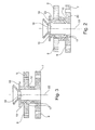
- the Fig. 2 shows a first embodiment of an inventive embodiment of a combustion chamber shingles 7. This has, as known from the prior art, effusion cooling holes 9 and is cooled by means of cooling air, which is supplied by impingement cooling holes 8 of the combustion chamber wall 6.
- the shingle 7 is provided with a tubular extension 15 which extends in the direction of the combustion chamber wall 6 and is performed by a recess 23 of the combustion chamber wall 6.
- the tubular extension 15 is formed integrally with the shingle 7, for example by means of a casting process.
- the tubular projection 15 has a connecting web 10, which forms an annular contact surface 20, against which the combustion chamber wall 6 abuts.
- the annular projection 15 is provided with a central recess 18, which forms a through hole for a spark plug.
- the Fig. 2 further shows a spark plug seal 16, which, since the tubular projection 15 extends through the combustion chamber wall 6, has a distance from the combustion chamber wall 6.
- the tubular extension 15 is further provided with a plurality of cooling air recesses 17 through which cooling air can be introduced into the recess 18 to cool the spark plug.
- the Fig. 3 shows a further embodiment in an analogous representation, the same parts are provided with the same reference numerals. On a repeated description can therefore be omitted.
- the shingle 7 is integrally formed with a portion of the combustion chamber wall 6 and made by a DLD method.
- the region of the combustion chamber wall 6 formed on the shingle 7 is connected to the remaining combustion chamber wall by suitable means.
Landscapes
- Engineering & Computer Science (AREA)
- Chemical & Material Sciences (AREA)
- Combustion & Propulsion (AREA)
- Mechanical Engineering (AREA)
- General Engineering & Computer Science (AREA)
- Ignition Installations For Internal Combustion Engines (AREA)
- Cylinder Crankcases Of Internal Combustion Engines (AREA)
Abstract
Description
- Die Erfindung bezieht sich auf eine Gasturbinenbrennkammer und insbesondere auf eine Gasturbinenbrennkammerschindel, welche zur Durchführung einer Zündkerze ausgebildet ist. Die Brennkammern von Gasturbinen, insbesondere von Fluggasturbinen weisen üblicherweise eine Brennkammerwand auf, welche eine Tragstruktur für Schindeln bildet. Die Schindeln sind an der Innenseite der Brennkammerwand angeordnet, um diese gegenüber dem Heißgas abzuschirmen und die Tragstruktur thermisch zu isolieren. Üblicherweise ist zwischen den Schindeln und der Tragstruktur ein Zwischenraum ausgebildet, durch welchen Kühlluft durchgeleitet wird.
- Derartige beschindelte Brennkammern sind beispielsweise aus der
EP 0 576 435 A1 , derEP 0 741 268 A1 oder derEP 1 710 501 A2 bekannt. Durch die Verwendung der beschriebenen Schindeln, welche mittels Prallkühlung gekühlt werden und mit Effusionskühllöchern versehen sind, wird die Trag- und Dichtstruktur der Brennkammerwand vor der intensiven Wärmestrahlung der Flamme geschützt. Die Trag- und Dichtstruktur bleibt dadurch auf einer niedrigeren Temperatur und behält ihre mechanische Festigkeit. - Zur Zündung von Brennkammern ist es erforderlich, zumindest eine Zündkerze durch die Brennkammerwand bzw. Tragstruktur sowie durch die Schindel durchzuführen, um den Brennraum der Brennkammer zu erreichen. Da die Zündkerze an einer Stelle im Gehäuse der Gasturbine befestigt ist, während die Brennkammer an einer anderen Stelle des Gehäuses gelagert ist, entstehen Relativbewegungen. Weiterhin ist es erforderlich, Bauteiltoleranzen durch die Beweglichkeit der Zündkerze in der Brennkammer auszugleichen, ohne dass eine Last auf die Zündkerze übertragen wird. Zusätzlich erhitzt sich die Brennkammer im Betrieb schneller und auf höhere Temperaturen, wodurch unterschiedliche Wärmeausdehnungen ausgeglichen werden müssen. Im Bereich der Zündkerzenbohrung erfolgt der Ausgleich von Bauteiltoleranzen und Wärmedehnungen durch eine Vergrößerung der Zündkerzenbohrung in der Brennkammer, sodass die Zündkerzenbohrung einen größeren Durchmesser aufweist, als die Zündkerze. Hierdurch entsteht ein Spalt, welcher durch eine Dichtung verschlossen werden muss.
- Aus der
US 7 093 441 B2 ist eine beschindelte Brennkammer vorbekannt, welche einen sogenannten Zündkerzenturm aufweist, durch welchen die Zündkerze abgedichtet geführt werden kann. Ein derartiger zusätzlicher Zündkerzenturm bringt zusätzliches Gewicht. Weiterhin sind zusätzliche Kosten für dessen Herstellung zu kalkulieren. Zusätzlich erzwingt der Zündkerzenturm einen Mindestabstand zwischen der Brennkammerwand und dem Gehäuse der Gasturbine. Hierdurch ergibt sich insbesondere bei kleineren Triebwerken ein größerer notwendiger Durchmesser des Druckgehäuses, wodurch die Kosten und das Gewicht erheblich erhöht werden. - Der Erfindung liegt die Aufgabe zugrunde, eine Gasturbinenbrennkammer mit einer Schindel zur Durchführung einer Zündkerze sowie eine Gasturbinenbrennkammerschindel zu schaffen, welche bei einfachem Aufbau und einfacher, kostengünstiger Herstellbarkeit die Nachteile des Standes der Technik vermeiden und eine sichere und einfache Anordnung einer Zündkerze ermöglichen.
- Erfindungsgemäß wird die Aufgabe durch die Merkmalskombinationen der unabhängigen Ansprüche gelöst. Die Unteransprüche zeigen weitere vorteilhafte Ausgestaltungen der Erfindung.
- Die Erfindung sieht somit vor, die Schindel mit einer Ausnehmung zur Durchführung einer Zündkerze zu versehen. Dabei ist ein rohrförmiger, kragenartiger Ansatz an der Schindel ausgebildet, welcher die Ausnehmung zur Durchführung der Zündkerze umschließt und sich von der dem Brennkammerinnenraum abgewandten Seite der Schindel aus erstreckt. Der rohrförmige Ansatz ist somit erfindungsgemäß so dimensioniert, dass er sich von der Schindel aus durch die Brennkammerwand (Tragstruktur) hindurch auf die Kaltseite der Brennkammerwand erstreckt. Der rohrförmige Ansatz ist dabei insbesondere so ausgebildet und dimensioniert, dass er mit einer engen Passung durch die in der Brennkammerwand oder Tragstruktur ausgebildete Ausnehmung geführt ist.
- Erfindungsgemäß ist somit kein separates Bauteil erforderlich, vielmehr wird die Schindel selbst in geeigneter Weise ausgebildet, um die Ausnehmung zur Durchführung der Zündkerze so auszubilden, dass die Zündkerze betriebssicher und einfach durchgeführt und gehalten werden kann.
- Die erfindungsgemäß vorgesehene Schindel ist, wie erwähnt, einstückig mit dem rohrförmigen Ansatz ausgebildet. Dabei kann die Schindel als Gussteil gefertigt werden oder mittels eines Laserauftragsschweißverfahrens (DLD) hergestellt werden.
- In besonders günstiger Weiterbildung der Erfindung ist vorgesehen, dass der rohrförmige Ansatz an seinem freien Endbereich, welcher durch die Brennkammerwand über die Kaltseite der Brennkammerwand hinausragt, mit einer Zündkerzendichtung versehen ist. Die Dichtung kann dabei insbesondere so ausgebildet werden, dass sie die Brennkammerwand (Tragstruktur) nicht berührt, um in diesem Bereich keinen Wärmeübergang zu schaffen.
- In weiterer vorteilhafter Ausgestaltung der Erfindung ist vorgesehen, dass der rohrförmige Ansatz oder Kragen mit einer ringförmigen Anlagefläche oder einer Stufe versehen ist, um den ringförmigen Ansatz gegen die Heißseite der Brennkammerwand (Tragstruktur) anzulegen. Hierdurch ergibt sich zum einen eine Abdichtung des zwischen der Brennkammerwand und der Schindel ausgebildeten Kühlluft-Zwischenraums. Zum anderen erfolgt hierdurch eine zusätzliche Abstützung und Lagerung der Schindel.
- In einer besonders vorteilhaften Weiterbildung der Erfindung ist vorgesehen, dass der rohrförmige Ansatz mit zumindest einer Kühlluftausnehmung versehen ist, durch welche Kühlluft zur innenliegenden Wandung des rohrförmigen Ansatzes und somit zur Zündkerze zugeführt werden kann, um diese zu kühlen.
- Die erfindungsgemäße Lösung weist somit den Vorteil auf, dass eine sichere Montage und Anordnung der Zündkerze ohne einen Zündkerzenturm möglich ist. Da die Schindel aus einem verschleißfesteren Material als die Brennkammerwand besteht, ist eine betriebssichere Lagerung und Positionierung der Zündkerze gewährleistet. Weiterhin kann erfindungsgemäß zur weiteren Verminderung von Bauteiltoleranzen das Zündkerzenloch (Ausnehmung des rohrförmigen Ansatzes) durch Positionierung relativ zur Halterung der Brennkammer in einem späteren Fertigungsschritt besonders präzise eingebracht werden. Um den Zusammenbau zu erleichtern, kann die oben erwähnte Zündkerzendichtung zusätzlich am Halter der Zündkerze befestigt werden.
- Im Folgenden wird die Erfindung anhand von Ausführungsbeispielen in Verbindung mit der Zeichnung beschrieben. Dabei zeigt:
- Fig. 1
- eine vereinfachte Schnittansicht einer Brennkammer gemäß dem Stand der Technik,
- Fig. 2
- eine Detail-Schnittansicht einer erfindungsgemäßen Brennkammerschindel mit rohrförmigem Ansatz, und
- Fig. 3
- ein weiteres Ausführungsbeispiel in analoger Darstellung der
Fig. 2 . - Die
Fig. 1 zeigt in schematischer Schnittansicht eine Gasturbinenbrennkammer 1, so wie diese aus dem Stand der Technik bekannt ist. Die Brennkammer 1 weist ein Hitzeschild 2 sowie einen Brennkammerkopf 3 und eine Brennerdichtung 4 auf. An einer kühlluftseitigen Brennkammerwand 6 sind mit einem Abstand zur Brennkammerwand 6 mehrere Schindeln 7 befestigt. - Weiterhin weisen die Brennkammerwand 6 und die Schindeln 7 Zumischlöcher 5 zur Zuführung von Luft auf. Die Befestigung der Schindeln 7 erfolgt über Bolzen 13 und Muttern 14, während die Brennkammerwand 6 mittels einer Brennkammeraufhängung 11 und einem Brennkammerflansch 12 gehaltert ist.
- Auf die Darstellung einer Zündkerze wurde der Übersichtlichkeit halber in
Fig. 1 verzichtet. Hierzu wird auf dieUS 7 093 441 B2 verwiesen. - Die
Fig. 2 zeigt ein erstes Ausführungsbeispiel einer erfindungsgemäßen Ausgestaltung einer Brennkammerschindel 7. Diese weist, wie aus dem Stand der Technik bekannt, Effusionskühllöcher 9 auf und wird mittels Kühlluft, welche durch Prallkühllöcher 8 der Brennkammerwand 6 zugeführt wird, gekühlt. - Erfindungsgemäß ist die Schindel 7 mit einem rohrförmigen Ansatz 15 versehen, welcher sich in Richtung der Brennkammerwand 6 erstreckt und durch eine Ausnehmung 23 der Brennkammerwand 6 durchgeführt ist. Der rohrförmige Ansatz 15 ist einstückig mit der Schindel 7 ausgebildet, beispielsweise mittels eines Gussverfahrens.
- Um einen vorgegebenen Abstand der Schindel 7 von der Brennkammerwand 6 sicherzustellen und um die Schindel 7 an der Brennkammerwand 6 zu positionieren, weist der rohrförmige Ansatz 15 einen Verbindungssteg 10 auf, welcher eine ringförmige Anlagefläche 20 bildet, gegen welche die Brennkammerwand 6 anliegt. Der ringförmige Ansatz 15 ist mit einer zentrischen Ausnehmung 18 versehen, welche ein Durchgangsloch für eine Zündkerze bildet.
- Die
Fig. 2 zeigt weiterhin eine Zündkerzendichtung 16, welche, da der rohrförmige Ansatz 15 die Brennkammerwand 6 durchragt, einen Abstand zur Brennkammerwand 6 aufweist. - Der rohrförmige Ansatz 15 ist weiterhin mit mehreren Kühlluftausnehmungen 17 versehen, durch welche Kühlluft in die Ausnehmung 18 eingeleitet werden kann, um die Zündkerze zu kühlen.
- Die
Fig. 3 zeigt ein weiteres Ausführungsbeispiel in analoger Darstellung, gleiche Teile sind mit gleichen Bezugsziffern versehen. Auf eine nochmalige Beschreibung kann deshalb verzichtet werden. Bei dem Ausführungsbeispiel derFig. 3 ist die Schindel 7 einstückig mit einem Bereich der Brennkammerwand 6 ausgebildet und mittels eines DLD-Verfahrens hergestellt. Der an der Schindel 7 ausgebildete Bereich der Brennkammerwand 6 ist mit geeigneten Mitteln mit der restlichen Brennkammerwand verbunden. -
- 1
- Brennkammer
- 2
- Hitzeschild
- 3
- Brennkammerkopf
- 4
- Brennerdichtung
- 5
- Zumischloch
- 6
- kühlluftseitige Brennkammerwand
- 7
- Schindel
- 8
- Prallkühlloch
- 9
- Effusionskühlloch
- 10
- Verbindungssteg
- 11
- Brennkammeraufhängung
- 12
- Brennkammerflansch
- 13
- Bolzen
- 14
- Mutter
- 15
- rohrförmiger Ansatz
- 16
- Zündkerzendichtung
- 17
- Kühlluftausnehmung
- 18
- Ausnehmung
- 19
- Brennkammerinnenraum
- 20
- ringförmige Anlagefläche
- 21
- Brennkammermittelachse
- 22
- Mittelachse
- 23
- Ausnehmung
Claims (8)
- Gasturbinenbrennkammerschindel mit einer Ausnehmung (18) zur Durchführung einer Zündkerze, dadurch gekennzeichnet, dass die Schindel (7) mit einem die Ausnehmung (18) umgebenden, sich von der einem Brennkammerinnenraum (19) abgewandten Seite der Schindel (7) aus erstreckenden rohrförmigen Ansatz (15) versehen ist.
- Schindel nach Anspruch 1, dadurch gekennzeichnet, dass der Ansatz (15) einstückig mit der Schindel (7) ausgebildet ist.
- Schindel nach Anspruch 1 oder 2, dadurch gekennzeichnet, dass der Ansatz (15) an seinem freien Endbereich mit einer Zündkerzendichtung (16) versehen ist.
- Schindel nach einem der Ansprüche 1 bis 3, dadurch gekennzeichnet, dass der Ansatz (15) an seinem Außenumfang mit einer ringförmigen Anlagefläche (20) versehen ist.
- Schindel nach einem der Ansprüche 1 bis 4, dadurch gekennzeichnet, dass der Ansatz (15) mit zumindest einer sich durch die Wandung des Ansatzes (15) erstreckenden Kühlluftausnehmung (17) versehen ist.
- Schindel nach einem der Ansprüche 1 bis 5, dadurch gekennzeichnet, dass die Schindel (7) mit dem Ansatz (15) als Gussteil ausgebildet ist.
- Schindel nach einem der Ansprüche 1 bis 5, dadurch gekennzeichnet, dass die Schindel (7) mit dem Ansatz (15) mittels eines Laserauftragsschweißverfahrens hergestellt ist.
- Gasturbinenbrennkammer mit einer Brennkammerwand (6), an welcher Schindeln (7) angeordnet sind, sowie mit einer sich durch die Brennkammerwand (6) und eine Schindel (7) erstreckenden Ausnehmung (18) zur Durchführung einer Zündkerze, dadurch gekennzeichnet, dass die Schindel (7) nach einem der Ansprüche 1 bis 7 ausgebildet ist.
Applications Claiming Priority (1)
| Application Number | Priority Date | Filing Date | Title |
|---|---|---|---|
| DE102013222932.1A DE102013222932A1 (de) | 2013-11-11 | 2013-11-11 | Gasturbinenbrennkammer mit Schindel zur Durchführung einer Zündkerze |
Publications (2)
| Publication Number | Publication Date |
|---|---|
| EP2871419A1 true EP2871419A1 (de) | 2015-05-13 |
| EP2871419B1 EP2871419B1 (de) | 2016-03-09 |
Family
ID=51868060
Family Applications (1)
| Application Number | Title | Priority Date | Filing Date |
|---|---|---|---|
| EP14191950.6A Not-in-force EP2871419B1 (de) | 2013-11-11 | 2014-11-05 | Gasturbinenbrennkammer mit Schindel zur Durchführung einer Zündkerze |
Country Status (3)
| Country | Link |
|---|---|
| US (1) | US20150135719A1 (de) |
| EP (1) | EP2871419B1 (de) |
| DE (1) | DE102013222932A1 (de) |
Cited By (2)
| Publication number | Priority date | Publication date | Assignee | Title |
|---|---|---|---|---|
| GB2531918A (en) * | 2014-10-27 | 2016-05-04 | Rolls Royce Plc | Igniter assembly |
| FR3071908A1 (fr) * | 2017-09-29 | 2019-04-05 | Safran Aircraft Engines | Chambre de combustion de turbomachine a geometrie de cheminee fixe |
Families Citing this family (20)
| Publication number | Priority date | Publication date | Assignee | Title |
|---|---|---|---|---|
| US10968829B2 (en) * | 2013-12-06 | 2021-04-06 | Raytheon Technologies Corporation | Cooling an igniter body of a combustor wall |
| US20160209035A1 (en) * | 2015-01-16 | 2016-07-21 | Solar Turbines Incorporated | Combustion hole insert with integrated film restarter |
| US10094564B2 (en) * | 2015-04-17 | 2018-10-09 | Pratt & Whitney Canada Corp. | Combustor dilution hole cooling system |
| US9810434B2 (en) * | 2016-01-21 | 2017-11-07 | Siemens Energy, Inc. | Transition duct system with arcuate ceramic liner for delivering hot-temperature gases in a combustion turbine engine |
| US10753283B2 (en) * | 2017-03-20 | 2020-08-25 | Pratt & Whitney Canada Corp. | Combustor heat shield cooling hole arrangement |
| US10670274B2 (en) | 2017-09-08 | 2020-06-02 | Raytheon Technologies Corporation | Cooling configurations for combustor attachment features |
| US10670275B2 (en) | 2017-09-08 | 2020-06-02 | Raytheon Technologies Corporation | Cooling configurations for combustor attachment features |
| US10670273B2 (en) | 2017-09-08 | 2020-06-02 | Raytheon Technologies Corporation | Cooling configurations for combustor attachment features |
| US10619857B2 (en) * | 2017-09-08 | 2020-04-14 | United Technologies Corporation | Cooling configuration for combustor attachment feature |
| US10330204B2 (en) * | 2017-11-10 | 2019-06-25 | Rolls-Royce Deutschland Ltd & Co Kg | Burner seal of a gas turbine and method for manufacturing the same |
| GB201804656D0 (en) | 2018-03-23 | 2018-05-09 | Rolls Royce Plc | An igniter seal arrangement for a combustion chamber |
| FR3088412B1 (fr) * | 2018-11-12 | 2022-07-15 | Safran Aircraft Engines | Chambre de combustion de turbomachine, turbomachine associee |
| US11371701B1 (en) | 2021-02-03 | 2022-06-28 | General Electric Company | Combustor for a gas turbine engine |
| US12146660B2 (en) | 2021-06-07 | 2024-11-19 | General Electric Company | Combustor for a gas turbine engine |
| US11885495B2 (en) | 2021-06-07 | 2024-01-30 | General Electric Company | Combustor for a gas turbine engine including a liner having a looped feature |
| US12085283B2 (en) | 2021-06-07 | 2024-09-10 | General Electric Company | Combustor for a gas turbine engine |
| US11774098B2 (en) | 2021-06-07 | 2023-10-03 | General Electric Company | Combustor for a gas turbine engine |
| US12152777B2 (en) | 2021-06-07 | 2024-11-26 | General Electric Company | Combustor for a gas turbine engine |
| US11959643B2 (en) | 2021-06-07 | 2024-04-16 | General Electric Company | Combustor for a gas turbine engine |
| CN115342383B (zh) * | 2022-07-06 | 2023-07-07 | 哈尔滨工程大学 | 一种采用混合旋流器的燃气轮机低污染燃烧室头部结构 |
Citations (7)
| Publication number | Priority date | Publication date | Assignee | Title |
|---|---|---|---|---|
| GB1442184A (en) * | 1972-10-02 | 1976-07-07 | Gen Electric | Gas turbine engine igniter assembly |
| EP0576435A1 (de) | 1991-03-22 | 1994-01-05 | Rolls Royce Plc | Gasturbinenbrennkammer. |
| EP0741268A1 (de) | 1995-05-03 | 1996-11-06 | United Technologies Corporation | Schutzplatten zur Auskleidung einer Gasturbinenbrennkammer |
| US7093441B2 (en) | 2003-10-09 | 2006-08-22 | United Technologies Corporation | Gas turbine annular combustor having a first converging volume and a second converging volume, converging less gradually than the first converging volume |
| EP1710501A2 (de) | 1999-11-06 | 2006-10-11 | Rolls-Royce plc | Wandelemente für Gasturbinenbrennkammer |
| US20100212324A1 (en) * | 2009-02-26 | 2010-08-26 | Honeywell International Inc. | Dual walled combustors with impingement cooled igniters |
| EP2330350A1 (de) * | 2009-11-23 | 2011-06-08 | Honeywell International Inc. | Doppelwandige Flammrohre mit prallgekühlten Zündern |
Family Cites Families (12)
| Publication number | Priority date | Publication date | Assignee | Title |
|---|---|---|---|---|
| US6557350B2 (en) * | 2001-05-17 | 2003-05-06 | General Electric Company | Method and apparatus for cooling gas turbine engine igniter tubes |
| US6715279B2 (en) * | 2002-03-04 | 2004-04-06 | General Electric Company | Apparatus for positioning an igniter within a liner port of a gas turbine engine |
| GB0227842D0 (en) * | 2002-11-29 | 2003-01-08 | Rolls Royce Plc | Sealing Arrangement |
| US20060231535A1 (en) * | 2005-04-19 | 2006-10-19 | Fuesting Timothy P | Method of welding a gamma-prime precipitate strengthened material |
| US7546739B2 (en) * | 2005-07-05 | 2009-06-16 | General Electric Company | Igniter tube and method of assembling same |
| FR2891350A1 (fr) * | 2005-09-29 | 2007-03-30 | Snecma Sa | Dispositif de guidage d'un element dans un orifice d'une paroi de chambre de combustion de turbomachine |
| GB0610800D0 (en) * | 2006-06-01 | 2006-07-12 | Rolls Royce Plc | Combustion chamber for a gas turbine engine |
| US8479490B2 (en) * | 2007-03-30 | 2013-07-09 | Honeywell International Inc. | Combustors with impingement cooled igniters and igniter tubes for improved cooling of igniters |
| JPWO2009122474A1 (ja) * | 2008-03-31 | 2011-07-28 | 川崎重工業株式会社 | ガスタービン燃焼器の冷却構造 |
| US8739546B2 (en) * | 2009-08-31 | 2014-06-03 | United Technologies Corporation | Gas turbine combustor with quench wake control |
| US8201412B2 (en) * | 2010-09-13 | 2012-06-19 | General Electric Company | Apparatus and method for cooling a combustor |
| EP2583784A1 (de) * | 2011-10-21 | 2013-04-24 | Siemens Aktiengesellschaft | Vorbereitung einer Schweißstelle vor dem Schweißen und Bauteil |
-
2013
- 2013-11-11 DE DE102013222932.1A patent/DE102013222932A1/de not_active Withdrawn
-
2014
- 2014-11-05 EP EP14191950.6A patent/EP2871419B1/de not_active Not-in-force
- 2014-11-11 US US14/538,294 patent/US20150135719A1/en not_active Abandoned
Patent Citations (7)
| Publication number | Priority date | Publication date | Assignee | Title |
|---|---|---|---|---|
| GB1442184A (en) * | 1972-10-02 | 1976-07-07 | Gen Electric | Gas turbine engine igniter assembly |
| EP0576435A1 (de) | 1991-03-22 | 1994-01-05 | Rolls Royce Plc | Gasturbinenbrennkammer. |
| EP0741268A1 (de) | 1995-05-03 | 1996-11-06 | United Technologies Corporation | Schutzplatten zur Auskleidung einer Gasturbinenbrennkammer |
| EP1710501A2 (de) | 1999-11-06 | 2006-10-11 | Rolls-Royce plc | Wandelemente für Gasturbinenbrennkammer |
| US7093441B2 (en) | 2003-10-09 | 2006-08-22 | United Technologies Corporation | Gas turbine annular combustor having a first converging volume and a second converging volume, converging less gradually than the first converging volume |
| US20100212324A1 (en) * | 2009-02-26 | 2010-08-26 | Honeywell International Inc. | Dual walled combustors with impingement cooled igniters |
| EP2330350A1 (de) * | 2009-11-23 | 2011-06-08 | Honeywell International Inc. | Doppelwandige Flammrohre mit prallgekühlten Zündern |
Cited By (5)
| Publication number | Priority date | Publication date | Assignee | Title |
|---|---|---|---|---|
| GB2531918A (en) * | 2014-10-27 | 2016-05-04 | Rolls Royce Plc | Igniter assembly |
| GB2531918B (en) * | 2014-10-27 | 2018-01-31 | Rolls Royce Plc | Igniter assembly for a combustor of a gas turbine engine |
| US10167781B2 (en) | 2014-10-27 | 2019-01-01 | Rolls-Royce Plc | Igniter assembly |
| FR3071908A1 (fr) * | 2017-09-29 | 2019-04-05 | Safran Aircraft Engines | Chambre de combustion de turbomachine a geometrie de cheminee fixe |
| US11391462B2 (en) | 2017-09-29 | 2022-07-19 | Safran Aircraft Engines | Turbine engine combustion chamber with fixed duct geometry |
Also Published As
| Publication number | Publication date |
|---|---|
| US20150135719A1 (en) | 2015-05-21 |
| DE102013222932A1 (de) | 2015-05-28 |
| EP2871419B1 (de) | 2016-03-09 |
Similar Documents
| Publication | Publication Date | Title |
|---|---|---|
| EP2871419B1 (de) | Gasturbinenbrennkammer mit Schindel zur Durchführung einer Zündkerze | |
| AT514813B1 (de) | Anordnung aus einem Zylinderkopf und einem Vorkammersystem | |
| DE102004021799B3 (de) | Abgas-Kompensator | |
| DE60024958T2 (de) | Gasturbinenbrennstoffeinspritzdüse und Montageverfahren | |
| EP2189720A1 (de) | Brenneranordnung | |
| DE3110098A1 (de) | Turbinenschaufel, insbesondere turbinenleitschaufel fuer gasturbinentriebwerke | |
| EP2527743B1 (de) | Segmentbauteil aus Hochtemperaturgussmaterial für eine Ringbrennkammer, Ringbrennkammer für ein Flugzeugtriebwerk, Flugzeugtriebwerk und Verfahren zur Herstellung einer Ringbrennkammer | |
| CH698278A2 (de) | Turbinen/Verdicherstator-Verbindung mit wärmeisoliertem Flanschbolzen. | |
| DE112019004946B4 (de) | Brennerkomponente, Brenner, Gasturbine und Herstellungsverfahren für Brennerkomponente | |
| DE102013109270A1 (de) | System und Verfahren für eine Schaufelabdeckplatte | |
| EP2807350B1 (de) | Dichtung für eine einrichtung zum nachbehandeln von abgasen einer brennkraftmaschine | |
| EP2362143B1 (de) | Brenneranordnung | |
| EP2054669B1 (de) | Brenner mit einem schutzelement für zündelektroden | |
| EP1904717B1 (de) | HEIßGASFÜHRENDES GEHÄUSEELEMENT, WELLENSCHUTZMANTEL UND GASTURBINENANLAGE | |
| EP2153040B1 (de) | Vorrichtung zum mechanisch entkoppelten befestigen einer von heissgas durchströmten flugzeugkomponente | |
| EP2409086B1 (de) | Brenneranordnung für eine gasturbine | |
| DE60224761T2 (de) | Balgartiges Überschlagrohr | |
| DE2348501A1 (de) | Zuendeinrichtung fuer gasturbinentriebwerk | |
| EP2347100B1 (de) | Gasturbine mit kühleinsatz | |
| EP2362141A1 (de) | Brenneranordnung | |
| EP2362142A1 (de) | Brenneranordnung | |
| EP2271876B1 (de) | Brenneranordnung für fluidische brennstoffe und verfahren zum herstellen einer brenneranordnung | |
| EP1422479B1 (de) | Brennkammer zur Verbrennung eines brennbaren Fluidgemisches | |
| EP2864705B1 (de) | Brennkammerkühlung | |
| EP2696036A1 (de) | Klemmring für eine Strömungsmaschine |
Legal Events
| Date | Code | Title | Description |
|---|---|---|---|
| PUAI | Public reference made under article 153(3) epc to a published international application that has entered the european phase |
Free format text: ORIGINAL CODE: 0009012 |
|
| 17P | Request for examination filed |
Effective date: 20141105 |
|
| AK | Designated contracting states |
Kind code of ref document: A1 Designated state(s): AL AT BE BG CH CY CZ DE DK EE ES FI FR GB GR HR HU IE IS IT LI LT LU LV MC MK MT NL NO PL PT RO RS SE SI SK SM TR |
|
| AX | Request for extension of the european patent |
Extension state: BA ME |
|
| R17P | Request for examination filed (corrected) |
Effective date: 20150427 |
|
| RBV | Designated contracting states (corrected) |
Designated state(s): AL AT BE BG CH CY CZ DE DK EE ES FI FR GB GR HR HU IE IS IT LI LT LU LV MC MK MT NL NO PL PT RO RS SE SI SK SM TR |
|
| RIC1 | Information provided on ipc code assigned before grant |
Ipc: F23R 3/00 20060101AFI20150529BHEP |
|
| GRAP | Despatch of communication of intention to grant a patent |
Free format text: ORIGINAL CODE: EPIDOSNIGR1 |
|
| INTG | Intention to grant announced |
Effective date: 20150817 |
|
| GRAS | Grant fee paid |
Free format text: ORIGINAL CODE: EPIDOSNIGR3 |
|
| GRAA | (expected) grant |
Free format text: ORIGINAL CODE: 0009210 |
|
| AK | Designated contracting states |
Kind code of ref document: B1 Designated state(s): AL AT BE BG CH CY CZ DE DK EE ES FI FR GB GR HR HU IE IS IT LI LT LU LV MC MK MT NL NO PL PT RO RS SE SI SK SM TR |
|
| REG | Reference to a national code |
Ref country code: GB Ref legal event code: FG4D Free format text: NOT ENGLISH |
|
| REG | Reference to a national code |
Ref country code: AT Ref legal event code: REF Ref document number: 779807 Country of ref document: AT Kind code of ref document: T Effective date: 20160315 Ref country code: CH Ref legal event code: EP |
|
| REG | Reference to a national code |
Ref country code: IE Ref legal event code: FG4D Free format text: LANGUAGE OF EP DOCUMENT: GERMAN |
|
| REG | Reference to a national code |
Ref country code: DE Ref legal event code: R096 Ref document number: 502014000439 Country of ref document: DE |
|
| REG | Reference to a national code |
Ref country code: LT Ref legal event code: MG4D |
|
| REG | Reference to a national code |
Ref country code: NL Ref legal event code: MP Effective date: 20160309 |
|
| PG25 | Lapsed in a contracting state [announced via postgrant information from national office to epo] |
Ref country code: FI Free format text: LAPSE BECAUSE OF FAILURE TO SUBMIT A TRANSLATION OF THE DESCRIPTION OR TO PAY THE FEE WITHIN THE PRESCRIBED TIME-LIMIT Effective date: 20160309 Ref country code: ES Free format text: LAPSE BECAUSE OF FAILURE TO SUBMIT A TRANSLATION OF THE DESCRIPTION OR TO PAY THE FEE WITHIN THE PRESCRIBED TIME-LIMIT Effective date: 20160309 Ref country code: GR Free format text: LAPSE BECAUSE OF FAILURE TO SUBMIT A TRANSLATION OF THE DESCRIPTION OR TO PAY THE FEE WITHIN THE PRESCRIBED TIME-LIMIT Effective date: 20160610 Ref country code: HR Free format text: LAPSE BECAUSE OF FAILURE TO SUBMIT A TRANSLATION OF THE DESCRIPTION OR TO PAY THE FEE WITHIN THE PRESCRIBED TIME-LIMIT Effective date: 20160309 Ref country code: NO Free format text: LAPSE BECAUSE OF FAILURE TO SUBMIT A TRANSLATION OF THE DESCRIPTION OR TO PAY THE FEE WITHIN THE PRESCRIBED TIME-LIMIT Effective date: 20160609 |
|
| PG25 | Lapsed in a contracting state [announced via postgrant information from national office to epo] |
Ref country code: RS Free format text: LAPSE BECAUSE OF FAILURE TO SUBMIT A TRANSLATION OF THE DESCRIPTION OR TO PAY THE FEE WITHIN THE PRESCRIBED TIME-LIMIT Effective date: 20160309 Ref country code: LT Free format text: LAPSE BECAUSE OF FAILURE TO SUBMIT A TRANSLATION OF THE DESCRIPTION OR TO PAY THE FEE WITHIN THE PRESCRIBED TIME-LIMIT Effective date: 20160309 Ref country code: PL Free format text: LAPSE BECAUSE OF FAILURE TO SUBMIT A TRANSLATION OF THE DESCRIPTION OR TO PAY THE FEE WITHIN THE PRESCRIBED TIME-LIMIT Effective date: 20160309 Ref country code: LV Free format text: LAPSE BECAUSE OF FAILURE TO SUBMIT A TRANSLATION OF THE DESCRIPTION OR TO PAY THE FEE WITHIN THE PRESCRIBED TIME-LIMIT Effective date: 20160309 Ref country code: SE Free format text: LAPSE BECAUSE OF FAILURE TO SUBMIT A TRANSLATION OF THE DESCRIPTION OR TO PAY THE FEE WITHIN THE PRESCRIBED TIME-LIMIT Effective date: 20160309 Ref country code: NL Free format text: LAPSE BECAUSE OF FAILURE TO SUBMIT A TRANSLATION OF THE DESCRIPTION OR TO PAY THE FEE WITHIN THE PRESCRIBED TIME-LIMIT Effective date: 20160309 |
|
| PG25 | Lapsed in a contracting state [announced via postgrant information from national office to epo] |
Ref country code: IS Free format text: LAPSE BECAUSE OF FAILURE TO SUBMIT A TRANSLATION OF THE DESCRIPTION OR TO PAY THE FEE WITHIN THE PRESCRIBED TIME-LIMIT Effective date: 20160709 Ref country code: EE Free format text: LAPSE BECAUSE OF FAILURE TO SUBMIT A TRANSLATION OF THE DESCRIPTION OR TO PAY THE FEE WITHIN THE PRESCRIBED TIME-LIMIT Effective date: 20160309 |
|
| REG | Reference to a national code |
Ref country code: FR Ref legal event code: PLFP Year of fee payment: 3 |
|
| PG25 | Lapsed in a contracting state [announced via postgrant information from national office to epo] |
Ref country code: SK Free format text: LAPSE BECAUSE OF FAILURE TO SUBMIT A TRANSLATION OF THE DESCRIPTION OR TO PAY THE FEE WITHIN THE PRESCRIBED TIME-LIMIT Effective date: 20160309 Ref country code: SM Free format text: LAPSE BECAUSE OF FAILURE TO SUBMIT A TRANSLATION OF THE DESCRIPTION OR TO PAY THE FEE WITHIN THE PRESCRIBED TIME-LIMIT Effective date: 20160309 Ref country code: RO Free format text: LAPSE BECAUSE OF FAILURE TO SUBMIT A TRANSLATION OF THE DESCRIPTION OR TO PAY THE FEE WITHIN THE PRESCRIBED TIME-LIMIT Effective date: 20160309 Ref country code: CZ Free format text: LAPSE BECAUSE OF FAILURE TO SUBMIT A TRANSLATION OF THE DESCRIPTION OR TO PAY THE FEE WITHIN THE PRESCRIBED TIME-LIMIT Effective date: 20160309 Ref country code: PT Free format text: LAPSE BECAUSE OF FAILURE TO SUBMIT A TRANSLATION OF THE DESCRIPTION OR TO PAY THE FEE WITHIN THE PRESCRIBED TIME-LIMIT Effective date: 20160711 |
|
| REG | Reference to a national code |
Ref country code: DE Ref legal event code: R097 Ref document number: 502014000439 Country of ref document: DE |
|
| PG25 | Lapsed in a contracting state [announced via postgrant information from national office to epo] |
Ref country code: IT Free format text: LAPSE BECAUSE OF FAILURE TO SUBMIT A TRANSLATION OF THE DESCRIPTION OR TO PAY THE FEE WITHIN THE PRESCRIBED TIME-LIMIT Effective date: 20160309 |
|
| PLBE | No opposition filed within time limit |
Free format text: ORIGINAL CODE: 0009261 |
|
| STAA | Information on the status of an ep patent application or granted ep patent |
Free format text: STATUS: NO OPPOSITION FILED WITHIN TIME LIMIT |
|
| PG25 | Lapsed in a contracting state [announced via postgrant information from national office to epo] |
Ref country code: DK Free format text: LAPSE BECAUSE OF FAILURE TO SUBMIT A TRANSLATION OF THE DESCRIPTION OR TO PAY THE FEE WITHIN THE PRESCRIBED TIME-LIMIT Effective date: 20160309 |
|
| 26N | No opposition filed |
Effective date: 20161212 |
|
| PG25 | Lapsed in a contracting state [announced via postgrant information from national office to epo] |
Ref country code: BG Free format text: LAPSE BECAUSE OF FAILURE TO SUBMIT A TRANSLATION OF THE DESCRIPTION OR TO PAY THE FEE WITHIN THE PRESCRIBED TIME-LIMIT Effective date: 20160609 Ref country code: BE Free format text: LAPSE BECAUSE OF NON-PAYMENT OF DUE FEES Effective date: 20161130 |
|
| PG25 | Lapsed in a contracting state [announced via postgrant information from national office to epo] |
Ref country code: SI Free format text: LAPSE BECAUSE OF FAILURE TO SUBMIT A TRANSLATION OF THE DESCRIPTION OR TO PAY THE FEE WITHIN THE PRESCRIBED TIME-LIMIT Effective date: 20160309 |
|
| REG | Reference to a national code |
Ref country code: IE Ref legal event code: MM4A |
|
| PG25 | Lapsed in a contracting state [announced via postgrant information from national office to epo] |
Ref country code: LU Free format text: LAPSE BECAUSE OF NON-PAYMENT OF DUE FEES Effective date: 20161130 |
|
| REG | Reference to a national code |
Ref country code: FR Ref legal event code: PLFP Year of fee payment: 4 |
|
| PG25 | Lapsed in a contracting state [announced via postgrant information from national office to epo] |
Ref country code: IE Free format text: LAPSE BECAUSE OF NON-PAYMENT OF DUE FEES Effective date: 20161105 |
|
| REG | Reference to a national code |
Ref country code: BE Ref legal event code: MM Effective date: 20161130 |
|
| PG25 | Lapsed in a contracting state [announced via postgrant information from national office to epo] |
Ref country code: HU Free format text: LAPSE BECAUSE OF FAILURE TO SUBMIT A TRANSLATION OF THE DESCRIPTION OR TO PAY THE FEE WITHIN THE PRESCRIBED TIME-LIMIT; INVALID AB INITIO Effective date: 20141105 |
|
| PG25 | Lapsed in a contracting state [announced via postgrant information from national office to epo] |
Ref country code: CY Free format text: LAPSE BECAUSE OF FAILURE TO SUBMIT A TRANSLATION OF THE DESCRIPTION OR TO PAY THE FEE WITHIN THE PRESCRIBED TIME-LIMIT Effective date: 20160309 Ref country code: MK Free format text: LAPSE BECAUSE OF FAILURE TO SUBMIT A TRANSLATION OF THE DESCRIPTION OR TO PAY THE FEE WITHIN THE PRESCRIBED TIME-LIMIT Effective date: 20160309 Ref country code: MC Free format text: LAPSE BECAUSE OF FAILURE TO SUBMIT A TRANSLATION OF THE DESCRIPTION OR TO PAY THE FEE WITHIN THE PRESCRIBED TIME-LIMIT Effective date: 20160309 |
|
| PG25 | Lapsed in a contracting state [announced via postgrant information from national office to epo] |
Ref country code: LI Free format text: LAPSE BECAUSE OF NON-PAYMENT OF DUE FEES Effective date: 20171130 Ref country code: CH Free format text: LAPSE BECAUSE OF NON-PAYMENT OF DUE FEES Effective date: 20171130 |
|
| PG25 | Lapsed in a contracting state [announced via postgrant information from national office to epo] |
Ref country code: MT Free format text: LAPSE BECAUSE OF FAILURE TO SUBMIT A TRANSLATION OF THE DESCRIPTION OR TO PAY THE FEE WITHIN THE PRESCRIBED TIME-LIMIT Effective date: 20160309 |
|
| PG25 | Lapsed in a contracting state [announced via postgrant information from national office to epo] |
Ref country code: TR Free format text: LAPSE BECAUSE OF FAILURE TO SUBMIT A TRANSLATION OF THE DESCRIPTION OR TO PAY THE FEE WITHIN THE PRESCRIBED TIME-LIMIT Effective date: 20160309 Ref country code: AL Free format text: LAPSE BECAUSE OF FAILURE TO SUBMIT A TRANSLATION OF THE DESCRIPTION OR TO PAY THE FEE WITHIN THE PRESCRIBED TIME-LIMIT Effective date: 20160309 |
|
| PGFP | Annual fee paid to national office [announced via postgrant information from national office to epo] |
Ref country code: DE Payment date: 20191127 Year of fee payment: 6 |
|
| PGFP | Annual fee paid to national office [announced via postgrant information from national office to epo] |
Ref country code: FR Payment date: 20191125 Year of fee payment: 6 |
|
| PGFP | Annual fee paid to national office [announced via postgrant information from national office to epo] |
Ref country code: GB Payment date: 20191127 Year of fee payment: 6 |
|
| REG | Reference to a national code |
Ref country code: AT Ref legal event code: MM01 Ref document number: 779807 Country of ref document: AT Kind code of ref document: T Effective date: 20191105 |
|
| PG25 | Lapsed in a contracting state [announced via postgrant information from national office to epo] |
Ref country code: AT Free format text: LAPSE BECAUSE OF NON-PAYMENT OF DUE FEES Effective date: 20191105 |
|
| REG | Reference to a national code |
Ref country code: DE Ref legal event code: R119 Ref document number: 502014000439 Country of ref document: DE |
|
| GBPC | Gb: european patent ceased through non-payment of renewal fee |
Effective date: 20201105 |
|
| PG25 | Lapsed in a contracting state [announced via postgrant information from national office to epo] |
Ref country code: FR Free format text: LAPSE BECAUSE OF NON-PAYMENT OF DUE FEES Effective date: 20201130 |
|
| PG25 | Lapsed in a contracting state [announced via postgrant information from national office to epo] |
Ref country code: DE Free format text: LAPSE BECAUSE OF NON-PAYMENT OF DUE FEES Effective date: 20210601 Ref country code: GB Free format text: LAPSE BECAUSE OF NON-PAYMENT OF DUE FEES Effective date: 20201105 |