EP2871027A1 - Bolzenspannwerkzeug - Google Patents
Bolzenspannwerkzeug Download PDFInfo
- Publication number
- EP2871027A1 EP2871027A1 EP20130192354 EP13192354A EP2871027A1 EP 2871027 A1 EP2871027 A1 EP 2871027A1 EP 20130192354 EP20130192354 EP 20130192354 EP 13192354 A EP13192354 A EP 13192354A EP 2871027 A1 EP2871027 A1 EP 2871027A1
- Authority
- EP
- European Patent Office
- Prior art keywords
- spindle
- bolt
- nut
- thread
- pull rod
- Prior art date
- Legal status (The legal status is an assumption and is not a legal conclusion. Google has not performed a legal analysis and makes no representation as to the accuracy of the status listed.)
- Granted
Links
Images

Classifications
-
- B—PERFORMING OPERATIONS; TRANSPORTING
- B25—HAND TOOLS; PORTABLE POWER-DRIVEN TOOLS; MANIPULATORS
- B25B—TOOLS OR BENCH DEVICES NOT OTHERWISE PROVIDED FOR, FOR FASTENING, CONNECTING, DISENGAGING OR HOLDING
- B25B29/00—Accessories
- B25B29/02—Bolt tensioners
-
- B—PERFORMING OPERATIONS; TRANSPORTING
- B25—HAND TOOLS; PORTABLE POWER-DRIVEN TOOLS; MANIPULATORS
- B25B—TOOLS OR BENCH DEVICES NOT OTHERWISE PROVIDED FOR, FOR FASTENING, CONNECTING, DISENGAGING OR HOLDING
- B25B21/00—Portable power-driven screw or nut setting or loosening tools; Attachments for drilling apparatus serving the same purpose
Definitions
- the present invention relates to a bolt tensioning tool for screwing a nut onto a bolt thread.
- the bolt tensioning tool is in particular designed to stretch the bolt during the screwing of the nut.
- US 2011/192257 A discloses a hydraulic bolt tensioning tool for securing a nut on a bolt.
- the bolt tensioning tool has a pull nut, a hydraulic press and a socket.
- the tension nut can be screwed onto the bolt.
- the hydraulic press pushes the pull nut off the socket, stretching the bolt.
- the base has a side window through which a key for moving the nut can be inserted.
- the hydraulic bolt tensioning tool proves to be very advantageous for bolts of large diameter, since in this case the nuts can be clamped by hand without applying a large torque. In particular, no provision must be made to support the counter-moment.
- the bolt tensioning tool serves for screwing a nut onto a bolt thread protruding from a workpiece.
- the bolt tensioning tool has a pull rod which has a mouth with an internal thread for screwing onto the bolt thread.
- a hollow spindle is arranged coaxially with the pull rod.
- a roller screw has an internal thread in the spindle, an external thread on the drawbar and arranged between the spindle and pull rod, in the internal thread and the external thread engaging rollers.
- a foot is provided for supporting the bolt tensioning tool in the setting direction, on the workpiece.
- the roller screw is located on the part of the spindle in setting direction on the foot.
- a nut provided for gripping the nut is coupled to the spindle by means of a torque-limited tractor.
- the roller screw generates a tensile force that stretches the pin.
- the pull rod pulls on the bolt, while the spindle is supported by the foot on the workpiece.
- the roller screw drive is essential in order to effectively transfer the torque impressed by the spindle into the axial movement of the pull rod in the case of the high-acting forces.
- the counter-moment can be applied to the workpiece by the adhesive force of the foot. The adhesive force increases with the increasing tensile force. The nut is dragged through the nut until the nut rests on the workpiece.
- the rollers are preferably rotationally symmetrical.
- the rollers can thus rotate about their own axis of rotation, without transmitting a torque or an axial force on the spindle and the tie rod.
- the rollers have a plurality of teeth which are arranged along the axis of rotation at equal intervals. Each tooth has a self-contained closed head line, which engages both the internal thread of the spindle and in the external thread of the drawbar.
- One embodiment provides a pivot bearing which is disposed along the axis between the spindle and the foot and decouples a rotational movement of the spindle from the foot.
- a torque coupling couples the spindle with the pull rod.
- the torque coupling helps to screw the jaw onto the bolt thread.
- the torque coupling is sized to overcome the frictional force between the female thread of the jaw and the male thread.
- the pull rod has a return mechanism.
- the return mechanism has a shaft rotatably coupled to the spindle, a rotor guided on the shaft and provided for in the setting direction stop for the rotor.
- the rotor is coupled via a spiral backdrop to the rotational movement of the shaft.
- the runner is coupled to the drawbar via a straight line parallel to the drawbar.
- the gate moves the rotor along the axis as the shaft rotates with the spindle. If the runner is inhibited in its movement in the setting direction by the stop, the shaft rotates indirectly through the runner the pull rod.
- the shaft and spindle rotate in the same direction.
- An embodiment provides that a pitch of the internal thread of the mouth is greater than a pitch of the internal thread of the spindle. This ensures that the nut can be held on the workpiece fitting.
- Fig. 1 shows a bolt 1, which protrudes partially with a bolt thread 2 from a workpiece 3 .
- a nut 4 is to be screwed onto the bolt thread 2 , so that there is a predefined tension between the bolt thread 2 and the nut 4 .
- the bolt tightening tool 5 shown moves along an axis 6, counter to the setting direction 7 of the nut 4 on the bolt 1. Meanwhile, the nut 4 is rotated clockwise 8 about the axis 6 to the nut 4 in the setting direction 7 in contact with the workpiece 3 hold.
- the bolt tensioning tool 5 is shown by way of example as an attachment for a screwdriver 9 .
- the screwdriver 9 has an electric motor 10, which is fed from a battery pack 11 .
- the electric motor 10 rotates an output shaft 13 about the axis 6.
- the bolt tensioning tool 5 has a closure 14 which is rotatably mounted on the output shaft 13 , for example, a square or a left-hand thread.
- the user can guide and hold the electric screwdriver 9 by means of a handle 15 during operation.
- the screwdriver 9 may also include a hydraulic or pneumatic drive.
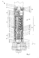
- Fig. 2 shows the bolt tensioning tool 5 in greater detail.
- the bolt tensioning tool 5 has a pull rod 16 arranged coaxially with respect to the axis 6.
- the pull rod 16 has at its rear end in the setting direction 7 a mouth 17 which can grip the bolt thread 2 .
- the bolt 1 is shown cut with his right half in the mouth 17 lying.
- the mouth 17 is provided for this purpose with an internal thread 18 which is chosen to match the bolt thread 2 .
- the internal thread 18 largely corresponds to the thread type the nut 4.
- a pull mechanism 19 pulls the pull bar 16 supported on the workpiece 3 against the setting direction 7, and thereby stretches the bolt 1.
- a nut 20 engages the nut 4.
- a tugboat 21 rotates the nut 20 in the clockwise direction 8, and holds by the nut 4 in support on the workpiece 3.
- the pulling mechanism 19 and the tractor 21 are driven by a spindle 22 .
- the screwdriver 9 is coupled to the spindle 22 .
- the drawbar 16 together with the pulling mechanism 19 and the nut 20 together with the tractor 21 are arranged within a supporting housing 23 .
- the drawbar 16 and the spindle 22 are connected via a roller screw 24 .
- the spindle 22 is hollow and has on its inside an internal thread 25.
- the tie rod 16 is arranged coaxially within the hollow spindle 22 .
- the pull rod 16 has an external thread 26.
- Fig. 2 shows drawbar 16 and spindle 22 cut in the left half of the drawing, in the right half in a side view.
- the two threads 25, 26 of the roller screw 24 are preferably more common. Their pitch and number of gears are the same.
- the pitch of the internal thread 25 is less than the pitch of the internal thread 18 of the mouth 17.
- the internal thread 25 of the spindle 22 does not engage in the external thread 26 of the tie rod 16 .
- An annular cavity surrounding the pull rod 16 spaces the two threads 25, 26 from each other.
- a plurality of rollers 27 are circumferentially arranged around the internal thread 25 distributed in the cavity.
- One of the rollers 27 is shown in the left half of the picture, in the right half of the image, the roller 27 for showing the threads 25, 26 of pull rod 16 and spindle 22 is not shown.
- the axes of rotation 28 of the rollers 27 are arranged parallel to the axis 6 at an equal radial distance from the axis 6 .
- Each of the rollers 27 has a toothing 29 which engages both the internal thread 25 and the external thread 26 .
- the toothing 29 consists of a plurality of teeth 30 which lie in planes perpendicular to the axis of rotation 28 .
- the toothing 29 is preferably rotationally symmetrical with corresponding disc-shaped teeth 30.
- the distance along the axis of rotation 28 between the teeth 30 is equal to the pitch of the internal thread 25 and the external thread 26.
- the rollers 27 are held in a cage 31 , which their distance in the direction of rotation determines the axis 6 .
- the exemplary cage 31 may rotate relative to the spindle 22 .
- the rollers 27 may be provided with a thread which is designed with the same pitch as the internal thread 25 .
- the spindle 22 may be fixed in the housing 23 along the axis 6 .
- the spindle 22 has a slight axial play and is biased by a spring 32 counter to the setting direction 7 .
- the spindle 22 is supported in the setting direction 7 via a rotary or roller bearing 33 on the housing 23 .
- the Housing 23 may for example be provided with a corresponding projection 34 or the output-side bearing shell anchored in the housing 23 .
- the drawbar 16 is along the axis 6 relative to the spindle 22 and corresponding to the housing 23 movable.
- the roller screw 24 forces a relative axial movement of the drawbar 16 and the spindle 22, when they perform a relative rotational movement to each other.
- the relative to the pull rod 16 rotated clockwise 8 spindle 22 leads to a movement of the drawbar 16 against the setting direction 7.
- the held by the mouth 17 of the tie rod 16 bolt 1 is thereby stretched by a tensile force.
- the opposing force introduces the bolt tensioning tool 5 with a foot 35 into the workpiece 3 .
- the foot 35 is placed in the setting direction 7 on the workpiece 3 spaced from the bolt 1 .
- the foot 35 is preferably a sleeve-shaped end portion of the housing 23.
- a footprint 36 of the foot 35 is, for example, annular.
- the nut 20 is attached to the nut 4 .
- the nut 20 has one or more key surfaces 137 abutting the outer contour of the nut 4 for transmitting torque.
- the nut 20 is formed complementary to the nut 4 , for example with a hexagonal prismatic cavity.
- the tractor 21 couples the nut 20 to the spindle 22 torque-limited.
- the exemplary tractor 21 has a friction based torque limit.
- the tractor 21 has two clutch plates 38, 39, between which a stack of prestressed disc springs 40 is arranged.
- the clutch plates 38, 39 are fixed to the housing 23 in the axial direction.
- the spindle 22 drives the one clutch disc 38 to rotate about the axis 6 .
- the spindle 22 is supported in the setting direction 7 on the clutch disc 38 .
- the other clutch disc 39 is coupled to the nut 20 .
- the nut 4 is continuously held in contact with the workpiece 3 , while the bolt 1 is stretched by the tie rod 16 .
- the transmitted torque is sufficient to overcome the friction of the nut 4 in the tensioned bolt 1 .
- the torque is less than a rated torque to which a torque wrench is set to set the nut 4 .
- the tractor 21 can not thus tension the bolt 1 by means of the nut 4 .
- Exemplary torque limits depend on the nut 20 , ie, the diameter of the nut 4 and bolt 1.
- the range for the limit is between 5% and 30% of the rated torque.
- the rated torque is in good estimate the diameter in the third power multiplied by 50 MN / m2, eg 400 Nm for a 20 mm bolt 1.
- the tractor 21 may include a freewheel 41 which transmits torque only in the clockwise direction 8 .
- the spindle 22 is coupled via a gear 42 with a drive spindle 37 of the bolt tensioning tool 5 .
- the drive spindle 37 is suitably connected to the output shaft 13 of the electric screwdriver 9 or a motor 10 .
- the bolt tensioning tool 5 is connected to the electric screwdriver 9 only via the drive spindle 37 .
- the housing 23 has no rotationally fixed mechanical coupling with the electric screwdriver 9 or the motor 10.
- the transmission 42 preferably includes one or more planetary gear stages.
- a planetary stage includes a sun gear 43, a plurality of planets 44 on a planet carrier 45, and a ring gear 46.
- the sun gear 43 of the first planetary stage is rotatably connected to the drive spindle 37 .
- the ring gear 46 of the stages is rotatably connected to the housing 23 .
- the planet carrier 45 is preferably non-rotatably connected to the sun gear of the next planetary stage.
- the planet carrier 47 of the last stage is rotatably connected to the spindle 22 .
- the planetary gear stages preferably mesh all with the common ring gear 46.
- the gearbox 42 reduces the speed of the drive spindle 37 to the spindle 22 and increases the torque accordingly.
- the counter-torque for the transmission 42 is supported by the ring gears on the housing 23 .
- the housing 23 with the ring gear 46 is freely rotatable relative to the drive spindle 37 . Due to the friction of the foot 35 with the workpiece 3, in particular when the pull rod 16 builds a tension, the counter-torque can be applied.
- the housing 23 is rotatable relative to the electric screwdriver 9 . The counter-torque can thus not affect the user.
- the transmission 42 may include a torque clutch 48 which, at low torque, couples the drive shaft 37 directly to the housing 23 .
- the drive spindle 37 thus rotates the housing 23 and the drive spindle 37 synchronously.
- the transmission 42 is bridged.
- the torque coupling 48 includes, for example, a spring 49, such as a plate spring, which is clamped along the axis 6 between the housing 23 and a collar 50 of the drive spindle 37 .
- An additional washer 51 may support the spring 49 .
- the disc 51 has axially extending projections 52 along the circumferential direction .
- the housing 23 also has axial projections 53.
- the projections 52, 53 are circumferentially offset from one another in a first position of the disc 51 , whereby the spring 49 can be relaxed , and a second position in axial alignment, whereby the spring 49 is biased to transmit the torque.
- the transmittable torque is preferably greater than the friction forces of the nut 4 on the bolt thread 2 and the mouth 17 on the bolt thread 2.
- the transmittable torque is limited in view of the holding force of the user this must apply the corresponding counter-torque. As explained below, no great holding force of the user is necessary for the function of the bolt tensioning tool 5 . Therefore, the torque clutch 48 advantageously disconnects at a low torque in the range between 2 Nm (Newton meters) to 10 Nm, which a user can hold with one hand in a typical electric screwdriver.
- the bolt tensioning tool 5 tensions the bolt 1 and unscrews the nut 4 as follows.
- the user uses the bolt 1 and screwed the nut 4 vorzugswiese by hand to rest on the workpiece 3 .
- the user sets the mouth 17 on the exposed upper end of the bolt thread 2 .
- the bolt thread 2 must project so far beyond the workpiece 3 that the foot 35 does not yet touch the workpiece 3 .
- the user turns on the motor 10, or the electric screwdriver 9 .
- the mouth 17 and the housing 23 initially exert only a slight counter-torque. The counter-torque results from the acceleration and possibly internal friction.
- the torque clutch 48 if present, bridges the transmission 42, causing the spindle 22 to rotate at the speed of the drive spindle 37 , otherwise squashed by the transmission 42.
- the roller screw 24 rotates the pull rod 16 in synchronism with the spindle 22 while rotating the jaw 17 on the bolt thread 2 .
- the process changes when the foot 35 touches the workpiece 3 .
- the mouth 17 can no longer rotate moment-free on the bolt thread 2 . Since the roller screw 24 can transmit only a small torque, pull rod 16 and spindle 22 are rotationally decoupled.
- the pull rod 16 stops while the spindle 22 is further driven to rotate. However, the roller screw 24 forces on the pull rod 16 an axial force against the setting direction 7.
- the bolt 1 is stretched.
- the tractor 21 retracts the nut 4 when it lifts off from the workpiece 3 due to the extended bolt 1 .
- the setting process is terminated when the applied tension reaches a predetermined setpoint.
- the tensile stress correlates with the torque which is introduced at the drive spindle 37 .
- a limitation of the introduced torque can be adjusted, for example, by means of the overload clutch 54 integrated in an electric screwdriver 9 .
- the direction of rotation of the drive spindle 37 is reversed to unscrew the mouth 17 of the bolt thread 2 .
- a return mechanism 55 ensures that while the pull rod 16 is brought a defined basic position. In the basic position, the pull rod 16 has advanced furthest in the setting direction 7 relative to the spindle 22 .
- Fig. 2 shows an exemplary return mechanism 55.
- the pull rod 16 is hollow.
- the return mechanism 55 has a threaded shaft 56 disposed in the hollow pull rod 16 .
- the shaft 56 is connected to the drive spindle 37 or the Spindle 22 coupled, whereby both rotate together with the same direction of rotation.
- a rotor 57 with a complementary thread sits on the shaft 56.
- the rotor 57 has a groove 58, engages the tie rod 16 with a web 59 .
- the web is preferably parallel to axis 6 and rectilinear.
- a relative rotational movement of the shaft 56 to the tie rod 16 causes an axial movement of the rotor 57.
- the sense of rotation of the thread of the shaft 56 is selected so that when the shaft 56 rotates clockwise 8 faster than the tie rod 16 , ie during the tightening of the Bolts 1, the rotor 57 moves against the setting direction 7 .
- a stop 60 is arranged in the setting direction 7 of the rotor 57 . As soon as the rotor 57 bears against the stop 60 , the shaft 56 forcibly rotates the pull rod 16 . The counterclockwise 8 rotated shaft 56 now rotates the pull rod 16 with the mouth 17 also counterclockwise 8 and thus of bolt thread 2 from.
Abstract
Description
- Die vorliegende Erfindung betrifft ein Bolzenspannwerkzeug zum Aufschrauben einer Mutter auf einem Bolzengewinde. Das Bolzenspannwerkzeug ist insbesondere ausgelegt, den Bolzen während des Aufschraubens der Mutter zu strecken.
-
US 2011/192257 A offenbart ein hydraulisches Bolzenspannwerkzeug zum Befestigen einer Mutter auf einem Bolzen. Das Bolzenspannwerkzeug hat eine Zugmutter, eine hydraulische Presse und einen Sockel. Die Zugmutter lässt sich auf den Bolzen aufschrauben. Die hydraulische Presse drückt die Zugmutter von dem Sockel ab, wodurch der Bolzen gestreckt wird. Der Sockel hat ein seitliches Fenster, durch welches ein Schlüssel zum Bewegen der Mutter eingeführt werden kann. - Das hydraulische Bolzenspannwerkzeug erweist sich für Bolzen großer Durchmesser als sehr vorteilhaft, da dabei die Muttern ohne Aufbringen eines großen Drehmoments per Hand gespannt werden können. Insbesondere müssen keine Vorkehrungen getroffen werden, um das Gegenmoment abzustützen.
- Das erfindungsgemäße Bolzenspannwerkzeug dient zum Aufschrauben einer Mutter auf ein aus einem Werkstück ragendes Bolzengewinde. Das Bolzenspannwerkzeug hat eine Zugstange, die ein Maul mit einem Innengewinde zum Aufschrauben auf das Bolzengewinde aufweist. Eine hohle Spindel ist koaxial zu der Zugstange angeordnet. Ein Rollengewindetrieb weist ein Innengewinde in der Spindel, ein Außengewinde an der Zugstange und zwischen Spindel und Zugstange angeordnete, in das Innengewinde und das Außengewinde eingreifende Rollen auf. Ein Fuß ist zum Abstützen des Bolzenspannwerkzeugs in Setzrichtung, auf dem Werkstück vorgesehen. Der Rollengewindetrieb liegt seitens der Spindel in Setzrichtung an dem Fuß an. Eine zum Greifen der Mutter vorgesehenen Nuss ist mittels eines Drehmoment-begrenzten Schleppers an die Spindel gekoppelt.
- Der Rollengewindetrieb erzeugt eine Zugkraft, welche den Bolzen streckt. Die Zugstange zieht dabei an dem Bolzen, während die Spindel sich über den Fuß am Werkstück abstützt. Der Rollengewindetrieb ist wesentlich, um bei den hohen wirkenden Kräften das von der Spindel eingeprägte Drehmoment effektiv in die axiale Bewegung der Zugstange zu übertragen. Das Gegenmoment kann durch die Haftkraft des Fußes an dem Werkstück aufgebracht werden. Die Haftkraft wächst mit der zunehmenden Zugkraft. Die Mutter wird durch die Nuss mitgeschleppt, bis die Mutter am Werkstück aufliegt.
- Die Rollen sind vorzugsweise rotationssymmetrisch. Die Rollen können sich somit um ihre eigene Drehachse drehen, ohne ein Drehmoment oder eine axiale Kraft auf die Spindel und die Zugstange zu übertragen. Die Rollen haben mehrere Zähne, die längs der Drehachse in gleichen Abständen angeordnet sind. Jeder Zahn hat eine in sich ringförmig geschlossene Kopflinie, die sowohl in das Innengewinde der Spindel als auch in das Außengewinde der Zugstange eingreift.
- Eine Ausgestaltung sieht ein Drehlager vor, das längs der Achse zwischen der Spindel und dem Fuß angeordnet ist und eine Drehbewegung der Spindel von dem Fuß entkoppelt.
- Eine Ausgestaltung sieht vor, dass eine Drehmomentkupplung die Spindel mit der Zugstange koppelt. Die Drehmomentkupplung unterstützt das Aufschrauben des Mauls auf das Bolzengewinde. Die Drehmomentkupplung ist dimensioniert, die Reibkraft zwischen dem Innengewinde des Mauls und dem Bolzengewinde zu überwinden.
- Eine Ausgestaltung sieht vor, dass die Zugstange einen Rückstellmechanismus aufweist. Der Rückstellmechanismus hat eine mit der Spindel drehgekoppelte Welle, einen auf der Welle geführten Läufer und einen in Setzrichtung vorgesehenen Anschlag für den Läufer. Der Läufer ist über eine spiralförmige Kulisse an die Drehbewegung der Welle angekoppelt. Der Läufer ist über eine zu der Zugstange parallele und geradlinige Führung mit der Zugstange gekoppelt. Die Kulisse verschiebt den Läufer längs der Achse, wenn die Welle sich mit der Spindel dreht. Wenn der Läufer in seiner Bewegung in Setzrichtung durch den Anschlag gehemmt ist, dreht die Welle mittelbar durch den Läufer die Zugstange. Die Welle und die Spindel drehen in gleichem Drehsinn.
- Eine Ausgestaltung sieht vor, dass eine Ganghöhe des Innengewindes des Mauls größer als eine Ganghöhe des Innengewindes der Spindel ist. Hierdurch ist gewährleistet, dass die Mutter auf dem Werkstück anliegend gehalten werden kann.
- Die nachfolgende Beschreibung erläutert die Erfindung anhand von exemplarischen Ausführungsformen und Figuren. In den Figuren zeigen:
-
Fig. 1 einen Schrauber mit einem Bolzenspannwerkzeug -
Fig. 2 das Bolzenspannwerkzeug - Gleiche oder funktionsgleiche Elemente werden durch gleiche Bezugszeichen in den Figuren indiziert, soweit nicht anders angegeben.
-
Fig. 1 zeigt einen Bolzen 1, der mit einem Bolzengewinde 2 teilweise aus einem Werkstück 3 ragt. Eine Mutter 4 soll auf das Bolzengewinde 2 aufgeschraubt werden, so dass sich zwischen dem Bolzengewinde 2 und der Mutter 4 eine vordefinierte Spannung ergibt. Das dargestellte Bolzenspannwerkzeug 5 zieht längs einer Achse 6, entgegen der Setzrichtung 7 der Mutter 4 an dem Bolzen 1. Währenddessen wird die Mutter 4 im Uhrzeigersinn 8 um die Achse 6 gedreht, um die Mutter 4 in Setzrichtung 7 in Auflage mit dem Werkstück 3 zu halten. - Das Bolzenspannwerkzeug 5 ist beispielhaft als Aufsatz für einen Schrauber 9 dargestellt. Der Schrauber 9 hat einen Elektromotor 10, der aus einem Batteriepaket 11 gespeist wird. Ansprechend auf ein Betätigen eines Haupttasters 12 dreht der Elektromotor 10 eine Abtriebswelle 13 um die Achse 6. Das Bolzenspannwerkzeug 5 hat einen Verschluss 14, welcher drehfest auf der Abtriebswelle 13 befestigbar ist, z.B. einen Vierkant oder ein Linksgewinde. Der Anwender kann den Elektroschrauber 9 mittels eines Handgriffs 15 während des Betriebs führen und Halten. Anstelle eines Elektromotors 10 kann der Schrauber 9 auch einen hydraulischen oder pneumatischen Antrieb enthalten.
-
Fig. 2 zeigt das Bolzenspannwerkzeug 5 in größerem Detail. Das Bolzenspannwerkzeug 5 hat eine koaxial zu der Achse 6 angeordnete Zugstange 16. Die Zugstange 16 hat an ihrem in Setzrichtung 7 hinteren Ende ein Maul 17, das das Bolzengewinde 2 greifen kann. Der Bolzen 1 ist angeschnitten mit seiner rechten Hälfte in dem Maul 17 liegend dargestellt. Das Maul 17 ist hierfür mit einem Innengewinde 18 versehen, das passend zu dem Bolzengewinde 2 gewählt ist. Das Innengewinde 18 entspricht weitgehend dem Gewindetyp der Mutter 4. Ein Zugmechanismus 19 zieht die Zugstange 16 abgestützt an dem Werkstück 3 entgegen der Setzrichtung 7 an, und streckt dabei den Bolzen 1. Eine Nuss 20 greift die Mutter 4. Ein Schlepper 21 dreht die Nuss 20 im Uhrzeigersinn 8, und hält dadurch die Mutter 4 in Auflage auf dem Werkstück 3. Der Zugmechanismus 19 und der Schlepper 21 sind von einer Spindel 22 angetrieben. Der Schrauber 9 ist mit der Spindel 22 gekoppelt. Die Zugstange 16 nebst Zugmechanismus 19 und die Nuss 20 nebst Schlepper 21 sind innerhalb eines tragenden Gehäuses 23 angeordnet. - Die Zugstange 16 und die Spindel 22 sind über ein Rollengewindetrieb 24 verbunden. Die Spindel 22 ist hohl ausgebildet und hat an ihrer Innenseite ein Innengewinde 25. Die Zugstange 16 ist koaxial innerhalb der hohlen Spindel 22 angeordnet. Die Zugstange 16 hat ein Außengewinde 26.
Fig. 2 zeigt in der linken Bildhälfte Zugstange 16 und Spindel 22 angeschnitten, in der rechten Bildhälfte in einer Seitenansicht. Die beiden Gewinde 25, 26 des Rollengewindetriebs 24 sind vorzugsweise mehrgängig. Ihre Ganghöhe und Gangzahl sind gleich. Die Ganghöhe des Innengewindes 25 ist geringer als die Ganghöhe des Innengewindes 18 des Mauls 17. Das Innengewinde 25 der Spindel 22 greift nicht in das Außengewinde 26 der Zugstange 16 ein. Ein die Zugstange 16 umgebender, ringförmiger Hohlraum beabstandet die beiden Gewinde 25, 26 voneinander. Mehrere Rollen 27 sind umfänglich um das Innengewinde 25 verteilt in dem Hohlraum angeordnet. Eine der Rollen 27 ist in der linken Bildhälfte dargestellt, in der rechten Bildhälfte ist die Rolle 27 zum Zeigen der Gewinde 25, 26 von Zugstange 16 und Spindel 22 nicht dargestellt. Die Drehachsen 28 der Rollen 27 sind parallel zu der Achse 6 in einem gleichen radialen Abstand zu der Achse 6 angeordnet. Jede der Rollen 27 hat eine Verzahnung 29, welche sowohl in das Innengewinde 25 als auch in das Außengewinde 26 eingreift. Die Verzahnung 29 besteht aus mehreren Zähnen 30, die in Ebenen senkrecht zu der Drehachse 28 liegen. Die Verzahnung 29 ist vorzugsweise rotationssymmetrisch mit entsprechend scheibenförmigen Zähnen 30. Der Abstand längs der Drehachse 28 zwischen den Zähnen 30 ist gleich der Ganghöhe des Innengewindes 25 und des Außengewindes 26. Die Rollen 27 sind in einem Käfig 31 gehalten, welcher deren Abstand in Drehrichtung um die Achse 6 festlegt. Der beispielhafte Käfig 31 kann sich gegenüber der Spindel 22 drehen. Alternativ können die Rollen 27 mit einem Gewinde versehen sein, das mit gleicher Steigung wie das Innengewinde 25 ausgelegt ist. - Die Spindel 22 kann in dem Gehäuse 23 längs der Achse 6 festgelegt sein. In der beispielhaft dargestellten Ausführungsform hat die Spindel 22 ein geringes axiales Spiel und ist durch eine Feder 32 entgegen der Setzrichtung 7 vorgespannt. Die Spindel 22 ist in Setzrichtung 7 über ein Dreh- oder Wälzlager 33 an dem Gehäuse 23 abgestützt. Das Gehäuse 23 kann z.B. mit einem entsprechenden Vorsprung 34 versehen sein oder die abtriebsseitige Lagerschale in dem Gehäuse 23 verankert sein. Die Zugstange 16 ist längs der Achse 6 gegenüber der Spindel 22 und entsprechend dem Gehäuse 23 beweglich.
- Der Rollengewindetrieb 24 erzwingt eine relative axiale Bewegung der Zugstange 16 und der Spindel 22, wenn diese zueinander eine relative Drehbewegung ausführen. Die relativ zu der Zugstange 16 im Uhrzeigersinn 8 gedrehte Spindel 22 führt zu einer Bewegung der Zugstange 16 entgegen der Setzrichtung 7. Der durch das Maul 17 der Zugstange 16 gehaltene Bolzen 1 wird dabei durch eine Zugkraft gestreckt. Die Gegenkraft leitet das Bolzenspannwerkzeug 5 mit einem Fuß 35 in das Werkstück 3 ein. Der Fuß 35 wird in Setzrichtung 7 auf das Werkstück 3 beabstandet zu dem Bolzen 1 aufgesetzt. Der Fuß 35 ist vorzugsweise ein hülsenförmiger Endabschnitt des Gehäuses 23. Eine Stellfläche 36 des Fußes 35 ist beispielsweise ringförmig.
- Die Nuss 20 ist auf die Mutter 4 aufgesteckt. Die Nuss 20 hat ein oder mehrere Schlüsselflächen 137, die an der Außenkontur der Mutter 4 zum Übertragen eines Drehmoments anliegen. Vorzugsweise ist die Nuss 20 komplementär zu der Mutter 4 ausgebildet, z.B. mit einem sechseckig prismatischen Hohlraum. Der Schlepper 21 koppelt die Nuss 20 an die Spindel 22 drehmoment-begrenzt an. Der beispielshafte Schlepper 21 hat eine auf Reibung basierende Drehmoment-Begrenzung. Der Schlepper 21 hat zwei Kupplungsscheiben 38, 39, zwischen welchen ein Stapel von vorgespannten Tellerfedern 40 angeordnet ist. Die Kupplungsscheiben 38, 39 sind an dem Gehäuse 23 in axialer Richtung festgelegt. Die Spindel 22 treibt die eine Kupplungsscheibe 38 um die Achse 6 drehend an. Beispielsweise ist die Spindel 22 in Setzrichtung 7 auf der Kupplungsscheibe 38 abgestützt. Die andere Kupplungsscheibe 39 ist mit der Nuss 20 gekoppelt. Die Mutter 4 wird fortlaufend in Auflage mit dem Werkstück 3 gehalten, während der Bolzen 1 durch die Zugstange 16 gestreckt wird. Das übertragene Drehmoment ist ausreichend, um die Reibung der Mutter 4 bei dem gespannten Bolzen 1 zu überwinden. Das Drehmoment ist geringer als ein Nenndrehmoment, auf welches ein Drehmomentschlüssel eingestellt wird, um die Mutter 4 zu setzen. Der Schlepper 21 kann somit nicht mittels der Mutter 4 den Bolzen 1 spannen. Beispielhafte Grenzwerte für das Drehmoment sind von der Nuss 20 abhängig, d.h. dem Durchmesser der Mutter 4 und des Bolzens 1. Der Bereich für den Grenzwert liegt zwischen 5 % und 30 % des Nenndrehmoments. Das Nenndrehmoment ist in guter Schätzung der Durchmesser in dritter Potenz multipliziert mit 50 MN/m2, z.B. 400 Nm für einen 20 mm Bolzen 1. Der Schlepper 21 kann einen Freilauf 41 beinhalten, welcher nur in dem Uhrzeigersinn 8 ein Drehmoment überträgt.
- Die Spindel 22 ist über ein Getriebe 42 mit einer Antriebsspindel 37 des Bolzenspannwerkzeugs 5 gekoppelt. Die Antriebsspindel 37 ist in geeigneter Weise mit der Abtriebswelle 13 des Elektroschraubers 9 oder einem Motor 10 verbunden. Das Bolzenspannwerkzeug 5 ist nur über die Antriebsspindel 37 mit dem Elektroschrauber 9 verbunden. Das Gehäuse 23 hat keine drehfeste mechanische Kopplung mit dem Elektroschrauber 9 oder dem Motor 10.
- Das Getriebe 42 beinhaltet vorzugsweise ein oder mehrere Planetengetriebestufen. Eine Planetenstufe enthält ein Sonnenrad 43, mehrere Planeten 44 auf einem Planetenträger 45 und ein Hohlrad 46. Das Sonnenrad 43 der ersten Planetenstufe ist drehfest mit der Antriebsspindel 37 verbunden. Das Hohlrad 46 der Stufen ist drehfest mit dem Gehäuse 23 verbunden. Der Planetenträger 45 ist vorzugsweise mit dem Sonnenrad der nächsten Planetenstufe drehfest verbunden. Der Planetenträger 47 der letzten Stufe ist mit der Spindel 22 drehfest verbunden. Die Planetengetriebestufen kämmen vorzugsweise alle mit dem gemeinsamen Hohlrad 46. Das Getriebe 42 untersetzt die Drehzahl von der Antriebsspindel 37 zu der Spindel 22 und erhöht entsprechend das Drehmoment. Das Gegenmoment für das Getriebe 42 wird durch die Hohlräder an dem Gehäuse 23 abgestützt. Das Gehäuse 23 mit dem Hohlrad 46 ist gegenüber der Antriebsspindel 37 frei drehbar. Aufgrund der Reibung des Fußes 35 mit dem Werkstück 3, insbesondere wenn die Zugstange 16 eine Spannung aufbaut, kann das Gegenmoment aufgebracht werden. Das Gehäuse 23 ist gegenüber dem Elektroschrauber 9 drehbar. Das Gegenmoment kann somit nicht auf den Anwender einwirken.
- Das Getriebe 42 kann eine Drehmomentkupplung 48 beinhalten, welche bei einem geringen Drehmoment die Antriebsspindel 37 direkt mit dem Gehäuse 23 koppelt. Die Antriebsspindel 37 dreht somit das Gehäuse 23 und die Antriebsspindel 37 synchron. Das Getriebe 42 ist dabei überbrückt. Die Drehmomentkupplung 48 beinhaltet beispielsweise eine Feder 49, z.B. eine Tellerfeder, die längs der Achse 6 zwischen dem Gehäuse 23 und einem Kragen 50 der Antriebsspindel 37 eingespannt ist. Eine zusätzliche Scheibe 51 kann die Feder 49 unterstützen. Die Scheibe 51 hat sich entlang der Umfangsrichtung zunehmend in axialer Richtung erhebende Vorsprünge 52. Das Gehäuse 23 hat ebenfalls axiale Vorsprünge 53. Die Vorsprünge 52, 53 sind in einer ersten Stellung der Scheibe 51 in Umfangsrichtung zueinander versetzt, wodurch die Feder 49 entspannt werden kann, und ein einer zweiten Stellung in axialer Flucht, wodurch die Feder 49 zum Übertragen des Drehmoments vorgespannt ist. Das übertragbare Drehmoment ist vorzugsweise größer als die Reibkräfte der Mutter 4 auf dem Bolzengewinde 2 und dem Maul 17 auf dem Bolzengewinde 2. Das übertragbare Drehmoment ist in Hinblick auf die Haltekraft des Anwenders beschränkt, da dieser das entsprechende Gegenmoment aufbringen muss. Wie nachfolgend erläutert ist für die Funktion des Bolzenspannwerkzeugs 5 keine große Haltekraft des Anwenders nötig. Deshalb trennt die Drehmomentkupplung 48 vorteilhaft bei einem niedrigen Drehmoment im Bereich zwischen von 2 Nm (Newtonmeter) bis 10 Nm, welche ein Anwender bei einem typischen Elektroschrauber einhändig halten kann.
- Das Bolzenspannwerkzeug 5 spannt den Bolzen 1 und schraubt die Mutter 4 wie folgt auf. Der Anwender setzt den Bolzen 1 ein und schraubt die Mutter 4 vorzugswiese per Hand bis auf Auflage mit dem Werkstück 3 auf. Der Anwender setzt das Maul 17 auf das freiliegende obere Ende des Bolzengewindes 2 auf. Das Bolzengewinde 2 muss soweit über das Werkstück 3 vorstehen, dass der Fuß 35 das Werkstück 3 noch nicht berührt. Der Anwender schaltet den Motor 10, bzw. den Elektroschrauber 9 ein. Das Maul 17 und das Gehäuse 23 üben anfänglich nur ein geringes Gegenmoment aus. Das Gegenmoment ergibt sich wegen dem Beschleunigen und ggf. innerer Reibung. Die Drehmomentkupplung 48, soweit vorhanden, überbrückt das Getriebe 42, wodurch sich die Spindel 22 mit der Drehzahl der Antriebsspindel 37 dreht, andernfalls untersetzt durch das Getriebe 42. Der Rollengewindetrieb 24 dreht die Zugstange 16 synchron mit der Spindel 22 und dreht dabei das Maul 17 auf das Bolzengewinde 2 auf. Der Vorgang ändert sich, wenn der Fuß 35 auf dem Werkstück 3 aufsetzt. Das Maul 17 kann sich nicht mehr momentfrei auf das Bolzengewinde 2 drehen. Da der Rollengewindetrieb 24 nur ein geringes Drehmoment übertragen kann, werden Zugstange 16 und Spindel 22 rotatorisch entkoppelt. Die Zugstange 16 bleibt stehen, während die Spindel 22 weiter drehend angetrieben ist. Der Rollengewindetrieb 24 erzwingt jedoch auf die Zugstange 16 eine axiale Kraft entgegen der Setzrichtung 7. Der Bolzen 1 wird gestreckt. Der Schlepper 21 zieht die Mutter 4 nach, wenn diese sich aufgrund des gestreckten Bolzens 1 vom Werkstück 3 abhebt. Der Setzvorgang wird beendet, wenn die ausgeübte Zugspannung einen vorgegebenen Sollwert erreicht. Die Zugspannung korreliert mit dem Drehmoment, welches an der Antriebsspindel 37 eingeleitet wird. Eine Begrenzung des eingeleiteten Drehmoments kann z.B. mit Hilfe der in einem Elektroschrauber 9 integrierten Überlastkupplung 54 eingestellt werden. Die Drehrichtung der Antriebsspindel 37 wird umgekehrt, um das Maul 17 von dem Bolzengewinde 2 abzuschrauben. Vorzugsweise sorgt ein Rückstellmechanismus 55 dafür, dass dabei die Zugstange 16 eine definierte Grundstellung gebracht wird. Bei der Grundstellung ist die Zugstange 16 am weitesten in Setzrichtung 7 gegenüber der Spindel 22 vorgerückt.
-
Fig. 2 zeigt einen beispielhaften Rückstellmechanismus 55. Die Zugstange 16 ist hohl. Der Rückstellmechanismus 55 hat eine mit einem Gewinde versehene Welle 56, die in der hohlen Zugstange 16 angeordnet ist. Die Welle 56 ist mit der Antriebsspindel 37 oder der Spindel 22 gekoppelt, wodurch sich beide gemeinsam mit gleichem Drehsinn drehen. Ein Läufer 57 mit einem komplementären Gewinde sitzt auf der Welle 56. Der Läufer 57 hat eine Nut 58, in die Zugstange 16 mit einem Steg 59 eingreift. Der Steg ist vorzugsweise zu Achse 6 parallel und geradlinig. Eine relative Drehbewegung der Welle 56 zu der Zugstange 16 bewirkt eine axiale Bewegung des Läufers 57. Der Drehsinn des Gewindes der Welle 56 ist so gewählt, dass wenn sich die Welle 56 im Uhrzeigersinn 8 schneller als die Zugstange 16 dreht, d.h. während des Anziehens des Bolzens 1, sich der Läufer 57 entgegen der Setzrichtung 7 bewegt. Anstelle der Nut 58 und des Steges 59 kann auch eine andere eine relative Drehung in eine axiale Bewegung umsetzende Kulisse die Welle 56 und die Zugstange 16 koppeln. Ein Anschlag 60 ist in Setzrichtung 7 des Läufers 57 angeordnet. Sobald der Läufer 57 an dem Anschlag 60 anliegt, dreht die Welle 56 die Zugstange 16 zwangsweise mit. Die entgegen dem Uhrzeigersinn 8 gedrehte Welle 56 dreht nun die Zugstange 16 mit dem Maul 17 ebenfalls entgegen dem Uhrzeigersinn 8 und damit von Bolzengewinde 2 ab.
Claims (7)
- Bolzenspannwerkzeug (5) zum Spannen einer Mutter (4) auf ein aus einem Werkstück (3) ragendes Bolzengewinde (2) mit:einer Zugstange (16), die ein Maul (17) mit einem Innengewinde (18) zum Aufschrauben auf das Bolzengewinde (2) aufweist,einer hohlen Spindel (22), die koaxial zu der Zugstange (16) angeordnet ist,einem Rollengewindetrieb (24), der ein Innengewinde (25) in der Spindel (22), ein Außengewinde (26) an der Zugstange (16) und zwischen Spindel (22) und Zugstange (16) angeordnete, in das Innengewinde (25) und das Außengewinde (26) eingreifende Rollen (27) aufweist,einem zum Abstützen des Bolzenspannwerkzeug (5) in Setzrichtung (7), auf dem Werkstück (3) vorgesehenen Fuß (35), wobei der Rollengewindetrieb (24) seitens der Spindel (22) in Setzrichtung (7) an dem Fuß (35) abgestützt ist, undeiner zum Greifen der Mutter (4) vorgesehenen Nuss (20), die mittels eines Drehmoment-begrenzten Schleppers (21) an die Spindel (22) gekoppelt ist.
- Bolzenspannwerkzeug (5) nach Anspruch 1, gekennzeichnet durch ein Drehlager (33), das längs der Achse (6) zwischen der Spindel (22) und dem Fuß (35) angeordnet ist und eine Drehbewegung der Spindel (22) von dem Fuß (35) entkoppelt.
- Bolzenspannwerkzeug (5) nach Anspruch 1 oder 2, dadurch gekennzeichnet, dass eine Drehmomentkupplung (48) die Spindel (22) mit der Zugstange (16) koppelt.
- Bolzenspannwerkzeug (5) nach einem der vorhergehenden Ansprüche, dadurch gekennzeichnet, dass eine Ganghöhe des Innengewindes (18) des Mauls (17) größer als eine Ganghöhe des Innengewindes (25) der Spindel (22) ist.
- Bolzenspannwerkzeug (5) nach einem der vorhergehenden Ansprüche, dadurch gekennzeichnet, dass die Rollen (27) jeweils mehrere um eine Drehachse (28) der Rolle (27) rotationssymmetrische Zähne aufweisen.
- Bolzenspannwerkzeug (5) nach einem der vorhergehenden Ansprüche, dadurch gekennzeichnet, dass die Zugstange (16) einen Rückstellmechanismus (55) aufweist, welcher eine mit der Spindel (22) drehgekoppelte Welle (56), einen auf der Welle (56) geführten Läufer (57) und einen in Setzrichtung (7) vorgesehenen Anschlag (60) für den Läufer (57) aufweist, wobei der Läufer (57) über eine spiralförmige Kulisse an die Drehbewegung der Welle (56) angekoppelt ist und der Läufer (57) über eine zu der Zugstange (16) parallele und geradlinige Führung mit der Zugstange (16) gekoppelt ist.
- Bolzenspannwerkzeug (5) nach einem der vorhergehenden Ansprüche, dadurch gekennzeichnet, dass der Spindel (22) ein Getriebe (42) mit einer Planetenstufe vorgeschaltet ist, und ein Hohlrad (46) der Planetenstufe drehfest mit dem Fuß (35) verbunden ist.
Priority Applications (1)
| Application Number | Priority Date | Filing Date | Title |
|---|---|---|---|
| EP13192354.2A EP2871027B1 (de) | 2013-11-11 | 2013-11-11 | Bolzenspannwerkzeug |
Applications Claiming Priority (1)
| Application Number | Priority Date | Filing Date | Title |
|---|---|---|---|
| EP13192354.2A EP2871027B1 (de) | 2013-11-11 | 2013-11-11 | Bolzenspannwerkzeug |
Publications (2)
| Publication Number | Publication Date |
|---|---|
| EP2871027A1 true EP2871027A1 (de) | 2015-05-13 |
| EP2871027B1 EP2871027B1 (de) | 2016-10-05 |
Family
ID=49578142
Family Applications (1)
| Application Number | Title | Priority Date | Filing Date |
|---|---|---|---|
| EP13192354.2A Not-in-force EP2871027B1 (de) | 2013-11-11 | 2013-11-11 | Bolzenspannwerkzeug |
Country Status (1)
| Country | Link |
|---|---|
| EP (1) | EP2871027B1 (de) |
Cited By (10)
| Publication number | Priority date | Publication date | Assignee | Title |
|---|---|---|---|---|
| WO2017211749A1 (en) * | 2016-06-07 | 2017-12-14 | Newfrey Llc | Testing apparatus for testing a joining connection |
| JP6479248B1 (ja) * | 2018-12-11 | 2019-03-06 | 株式会社東日製作所 | 締付装置 |
| JP6479249B1 (ja) * | 2018-12-11 | 2019-03-06 | 株式会社東日製作所 | 締付装置 |
| CN109605284A (zh) * | 2019-01-31 | 2019-04-12 | 中国工程物理研究院机械制造工艺研究所 | 一种螺栓预紧拉伸装置及方法 |
| WO2020126098A1 (en) * | 2018-12-21 | 2020-06-25 | Caterpillar Energy Solutions Gmbh | Device for tensioning a connecting element |
| WO2020126095A1 (en) * | 2018-12-21 | 2020-06-25 | Caterpillar Energy Solutions Gmbh | Device for tensioning a connecting element |
| EP3733349A1 (de) * | 2019-04-30 | 2020-11-04 | Hohmann, Frank | Spannvorrichtung für eine schraubverbindung |
| CN112475873A (zh) * | 2020-12-31 | 2021-03-12 | 无锡市嘉立德科技有限公司 | 一种高通用性高速自动打螺丝装置 |
| CN112584977A (zh) * | 2018-06-20 | 2021-03-30 | 帕腾科技快推有限公司 | 用于拧紧螺栓上的螺母以形成固定连接的工具 |
| GB2580102B (en) * | 2018-12-21 | 2021-08-25 | Caterpillar Energy Solutions Gmbh | System for tensioning at least one connecting element |
Citations (5)
| Publication number | Priority date | Publication date | Assignee | Title |
|---|---|---|---|---|
| US1387895A (en) * | 1918-11-26 | 1921-08-16 | James P Mcbride | Bolting-up and plate-tightening machine |
| SU1106651A1 (ru) * | 1982-06-07 | 1984-08-07 | Предприятие П/Я В-8721 | Устройство дл сборки резьбовых соединений |
| CS233115B1 (cs) * | 1983-06-29 | 1985-02-14 | Jan Mlynarik | Zařízení pro utahování a předepínání nebo povolování šroubů a matic |
| JPH0825244A (ja) * | 1994-07-21 | 1996-01-30 | Besutoma Kk | ボルト継手における締結力の管理装置 |
| US20110192257A1 (en) | 2010-02-09 | 2011-08-11 | Titan Technologies International, Inc. | Hydraulic Bolt Tensioner and Nut |
-
2013
- 2013-11-11 EP EP13192354.2A patent/EP2871027B1/de not_active Not-in-force
Patent Citations (5)
| Publication number | Priority date | Publication date | Assignee | Title |
|---|---|---|---|---|
| US1387895A (en) * | 1918-11-26 | 1921-08-16 | James P Mcbride | Bolting-up and plate-tightening machine |
| SU1106651A1 (ru) * | 1982-06-07 | 1984-08-07 | Предприятие П/Я В-8721 | Устройство дл сборки резьбовых соединений |
| CS233115B1 (cs) * | 1983-06-29 | 1985-02-14 | Jan Mlynarik | Zařízení pro utahování a předepínání nebo povolování šroubů a matic |
| JPH0825244A (ja) * | 1994-07-21 | 1996-01-30 | Besutoma Kk | ボルト継手における締結力の管理装置 |
| US20110192257A1 (en) | 2010-02-09 | 2011-08-11 | Titan Technologies International, Inc. | Hydraulic Bolt Tensioner and Nut |
Cited By (26)
| Publication number | Priority date | Publication date | Assignee | Title |
|---|---|---|---|---|
| WO2017211749A1 (en) * | 2016-06-07 | 2017-12-14 | Newfrey Llc | Testing apparatus for testing a joining connection |
| CN112584977A (zh) * | 2018-06-20 | 2021-03-30 | 帕腾科技快推有限公司 | 用于拧紧螺栓上的螺母以形成固定连接的工具 |
| CN112584977B (zh) * | 2018-06-20 | 2022-09-27 | 快推有限公司 | 用于拧紧螺栓上的螺母以形成固定连接的工具 |
| JP6479248B1 (ja) * | 2018-12-11 | 2019-03-06 | 株式会社東日製作所 | 締付装置 |
| JP6479249B1 (ja) * | 2018-12-11 | 2019-03-06 | 株式会社東日製作所 | 締付装置 |
| US11772213B2 (en) | 2018-12-11 | 2023-10-03 | Tohnichi Mfg.Co., Ltd. | Tightening device |
| TWI693127B (zh) * | 2018-12-11 | 2020-05-11 | 日商東日製作所股份有限公司 | 緊固裝置 |
| WO2020121550A1 (ja) * | 2018-12-11 | 2020-06-18 | 株式会社東日製作所 | 締付装置 |
| JP2020093320A (ja) * | 2018-12-11 | 2020-06-18 | 株式会社東日製作所 | 締付装置 |
| WO2020121549A1 (ja) * | 2018-12-11 | 2020-06-18 | 株式会社東日製作所 | 締付装置 |
| JP2020093319A (ja) * | 2018-12-11 | 2020-06-18 | 株式会社東日製作所 | 締付装置 |
| US11364580B2 (en) | 2018-12-11 | 2022-06-21 | Tohnichi Mfg. Co., Ltd. | Fastening device |
| GB2580090B (en) * | 2018-12-21 | 2021-08-25 | Caterpillar Energy Solutions Gmbh | Device for tensioning a connecting element |
| CN113518692A (zh) * | 2018-12-21 | 2021-10-19 | 卡特彼勒能源方案有限公司 | 用于张紧连接元件的装置 |
| CN113518692B (zh) * | 2018-12-21 | 2023-03-10 | 卡特彼勒能源方案有限公司 | 用于张紧连接元件的装置 |
| GB2580104B (en) * | 2018-12-21 | 2021-04-28 | Caterpillar Energy Solutions Gmbh | Device for tensioning a connecting element |
| CN113195166A (zh) * | 2018-12-21 | 2021-07-30 | 卡特彼勒能源方案有限公司 | 用于张紧连接元件的装置 |
| GB2580102B (en) * | 2018-12-21 | 2021-08-25 | Caterpillar Energy Solutions Gmbh | System for tensioning at least one connecting element |
| GB2580104A (en) * | 2018-12-21 | 2020-07-15 | Caterpillar Energy Solutions Gmbh | Device for tensioning a connecting element |
| WO2020126098A1 (en) * | 2018-12-21 | 2020-06-25 | Caterpillar Energy Solutions Gmbh | Device for tensioning a connecting element |
| US20220080569A1 (en) * | 2018-12-21 | 2022-03-17 | Caterpillar Energy Solutions Gmbh | Device for Tensioning a Connecting Element |
| WO2020126095A1 (en) * | 2018-12-21 | 2020-06-25 | Caterpillar Energy Solutions Gmbh | Device for tensioning a connecting element |
| CN109605284A (zh) * | 2019-01-31 | 2019-04-12 | 中国工程物理研究院机械制造工艺研究所 | 一种螺栓预紧拉伸装置及方法 |
| EP3733349A1 (de) * | 2019-04-30 | 2020-11-04 | Hohmann, Frank | Spannvorrichtung für eine schraubverbindung |
| CN112475873B (zh) * | 2020-12-31 | 2022-04-08 | 无锡市嘉立德科技有限公司 | 一种高通用性高速自动打螺丝装置 |
| CN112475873A (zh) * | 2020-12-31 | 2021-03-12 | 无锡市嘉立德科技有限公司 | 一种高通用性高速自动打螺丝装置 |
Also Published As
| Publication number | Publication date |
|---|---|
| EP2871027B1 (de) | 2016-10-05 |
Similar Documents
| Publication | Publication Date | Title |
|---|---|---|
| EP2871027B1 (de) | Bolzenspannwerkzeug | |
| DE4406946C2 (de) | Blindnietmutter-Setzgerät | |
| EP2599568B1 (de) | Bohrvorrichtung | |
| EP1307313B1 (de) | Handwerkzeugmaschine | |
| DE2919744A1 (de) | Drehmomentabhaengige drehzahlumschalteinrichtung fuer motorschrauber | |
| DE10060635A1 (de) | Motorantrieb mit Getriebe-Werkzeughalter | |
| EP0528262A2 (de) | Mechanische Spannvorrichtung | |
| DE3801972A1 (de) | Kraftschrauber | |
| DE102010001013B4 (de) | Krafterhöhend selbstsperrendes Bohrfutter und seine Selbstsperrvorrichtung | |
| EP3957441A1 (de) | Blindnietbefestiger-setzvorrichtung | |
| DE2110112B2 (de) | DrehmomeHtbegrenzungs- und Trennkupplungseinrichtung an einem Schrauber | |
| WO2014044390A1 (de) | Spannsystem mit einem rotationsantrieb | |
| DE102004005367B4 (de) | Vorrichtung zur automatischen Änderung des Untersetzungsverhältnisses | |
| CH632325A5 (de) | Schlingfederkupplung, insbesondere fuer aufzeichnungs- und/oder wiedergabegeraete. | |
| DE3919648C2 (de) | Winkelschrauber | |
| EP2216555B1 (de) | Spanneinrichtung | |
| EP0840021A1 (de) | Vorrichtung zum Verbinden von Bauteilen | |
| DE3434850C2 (de) | Mehrfachschrauber | |
| EP1258321B1 (de) | Kraftgetriebener Schrauber mit Drehmomentbegrenzungskupplung | |
| EP0275331A1 (de) | Spannwelle | |
| DE2739489C3 (de) | Ausrückkupplung | |
| DE3101080A1 (de) | "kupplung fuer ein kraftwerkzeug" | |
| DE60002417T2 (de) | Stellglied mit drehmomentbeschränkung und beibehaltung der druck- und/oder zugkraft | |
| DE1245245B (de) | Umlaufraedergetriebe mit erhoehter Anfahrkraft, insbesondere fuer Schraubwerkzeuge | |
| DE19942292A1 (de) | Zwischenglied für eine Handschrauberwelle |
Legal Events
| Date | Code | Title | Description |
|---|---|---|---|
| PUAI | Public reference made under article 153(3) epc to a published international application that has entered the european phase |
Free format text: ORIGINAL CODE: 0009012 |
|
| 17P | Request for examination filed |
Effective date: 20131111 |
|
| AK | Designated contracting states |
Kind code of ref document: A1 Designated state(s): AL AT BE BG CH CY CZ DE DK EE ES FI FR GB GR HR HU IE IS IT LI LT LU LV MC MK MT NL NO PL PT RO RS SE SI SK SM TR |
|
| AX | Request for extension of the european patent |
Extension state: BA ME |
|
| R17P | Request for examination filed (corrected) |
Effective date: 20151113 |
|
| RBV | Designated contracting states (corrected) |
Designated state(s): AL AT BE BG CH CY CZ DE DK EE ES FI FR GB GR HR HU IE IS IT LI LT LU LV MC MK MT NL NO PL PT RO RS SE SI SK SM TR |
|
| GRAP | Despatch of communication of intention to grant a patent |
Free format text: ORIGINAL CODE: EPIDOSNIGR1 |
|
| INTG | Intention to grant announced |
Effective date: 20160623 |
|
| INTG | Intention to grant announced |
Effective date: 20160627 |
|
| GRAS | Grant fee paid |
Free format text: ORIGINAL CODE: EPIDOSNIGR3 |
|
| GRAA | (expected) grant |
Free format text: ORIGINAL CODE: 0009210 |
|
| AK | Designated contracting states |
Kind code of ref document: B1 Designated state(s): AL AT BE BG CH CY CZ DE DK EE ES FI FR GB GR HR HU IE IS IT LI LT LU LV MC MK MT NL NO PL PT RO RS SE SI SK SM TR |
|
| REG | Reference to a national code |
Ref country code: GB Ref legal event code: FG4D Free format text: NOT ENGLISH |
|
| REG | Reference to a national code |
Ref country code: CH Ref legal event code: EP |
|
| REG | Reference to a national code |
Ref country code: AT Ref legal event code: REF Ref document number: 834200 Country of ref document: AT Kind code of ref document: T Effective date: 20161015 |
|
| REG | Reference to a national code |
Ref country code: IE Ref legal event code: FG4D Free format text: LANGUAGE OF EP DOCUMENT: GERMAN |
|
| REG | Reference to a national code |
Ref country code: FR Ref legal event code: PLFP Year of fee payment: 4 |
|
| REG | Reference to a national code |
Ref country code: DE Ref legal event code: R096 Ref document number: 502013004851 Country of ref document: DE |
|
| REG | Reference to a national code |
Ref country code: NL Ref legal event code: MP Effective date: 20161005 |
|
| REG | Reference to a national code |
Ref country code: LT Ref legal event code: MG4D |
|
| PG25 | Lapsed in a contracting state [announced via postgrant information from national office to epo] |
Ref country code: LV Free format text: LAPSE BECAUSE OF FAILURE TO SUBMIT A TRANSLATION OF THE DESCRIPTION OR TO PAY THE FEE WITHIN THE PRESCRIBED TIME-LIMIT Effective date: 20161005 Ref country code: BE Free format text: LAPSE BECAUSE OF NON-PAYMENT OF DUE FEES Effective date: 20161130 |
|
| PG25 | Lapsed in a contracting state [announced via postgrant information from national office to epo] |
Ref country code: LT Free format text: LAPSE BECAUSE OF FAILURE TO SUBMIT A TRANSLATION OF THE DESCRIPTION OR TO PAY THE FEE WITHIN THE PRESCRIBED TIME-LIMIT Effective date: 20161005 Ref country code: NO Free format text: LAPSE BECAUSE OF FAILURE TO SUBMIT A TRANSLATION OF THE DESCRIPTION OR TO PAY THE FEE WITHIN THE PRESCRIBED TIME-LIMIT Effective date: 20170105 Ref country code: GR Free format text: LAPSE BECAUSE OF FAILURE TO SUBMIT A TRANSLATION OF THE DESCRIPTION OR TO PAY THE FEE WITHIN THE PRESCRIBED TIME-LIMIT Effective date: 20170106 Ref country code: SE Free format text: LAPSE BECAUSE OF FAILURE TO SUBMIT A TRANSLATION OF THE DESCRIPTION OR TO PAY THE FEE WITHIN THE PRESCRIBED TIME-LIMIT Effective date: 20161005 |
|
| PG25 | Lapsed in a contracting state [announced via postgrant information from national office to epo] |
Ref country code: NL Free format text: LAPSE BECAUSE OF FAILURE TO SUBMIT A TRANSLATION OF THE DESCRIPTION OR TO PAY THE FEE WITHIN THE PRESCRIBED TIME-LIMIT Effective date: 20161005 Ref country code: HR Free format text: LAPSE BECAUSE OF FAILURE TO SUBMIT A TRANSLATION OF THE DESCRIPTION OR TO PAY THE FEE WITHIN THE PRESCRIBED TIME-LIMIT Effective date: 20161005 Ref country code: RS Free format text: LAPSE BECAUSE OF FAILURE TO SUBMIT A TRANSLATION OF THE DESCRIPTION OR TO PAY THE FEE WITHIN THE PRESCRIBED TIME-LIMIT Effective date: 20161005 Ref country code: PL Free format text: LAPSE BECAUSE OF FAILURE TO SUBMIT A TRANSLATION OF THE DESCRIPTION OR TO PAY THE FEE WITHIN THE PRESCRIBED TIME-LIMIT Effective date: 20161005 Ref country code: FI Free format text: LAPSE BECAUSE OF FAILURE TO SUBMIT A TRANSLATION OF THE DESCRIPTION OR TO PAY THE FEE WITHIN THE PRESCRIBED TIME-LIMIT Effective date: 20161005 Ref country code: IS Free format text: LAPSE BECAUSE OF FAILURE TO SUBMIT A TRANSLATION OF THE DESCRIPTION OR TO PAY THE FEE WITHIN THE PRESCRIBED TIME-LIMIT Effective date: 20170205 Ref country code: ES Free format text: LAPSE BECAUSE OF FAILURE TO SUBMIT A TRANSLATION OF THE DESCRIPTION OR TO PAY THE FEE WITHIN THE PRESCRIBED TIME-LIMIT Effective date: 20161005 Ref country code: PT Free format text: LAPSE BECAUSE OF FAILURE TO SUBMIT A TRANSLATION OF THE DESCRIPTION OR TO PAY THE FEE WITHIN THE PRESCRIBED TIME-LIMIT Effective date: 20170206 |
|
| REG | Reference to a national code |
Ref country code: CH Ref legal event code: PL |
|
| REG | Reference to a national code |
Ref country code: DE Ref legal event code: R097 Ref document number: 502013004851 Country of ref document: DE |
|
| PG25 | Lapsed in a contracting state [announced via postgrant information from national office to epo] |
Ref country code: EE Free format text: LAPSE BECAUSE OF FAILURE TO SUBMIT A TRANSLATION OF THE DESCRIPTION OR TO PAY THE FEE WITHIN THE PRESCRIBED TIME-LIMIT Effective date: 20161005 Ref country code: CH Free format text: LAPSE BECAUSE OF NON-PAYMENT OF DUE FEES Effective date: 20161130 Ref country code: LI Free format text: LAPSE BECAUSE OF NON-PAYMENT OF DUE FEES Effective date: 20161130 Ref country code: MC Free format text: LAPSE BECAUSE OF FAILURE TO SUBMIT A TRANSLATION OF THE DESCRIPTION OR TO PAY THE FEE WITHIN THE PRESCRIBED TIME-LIMIT Effective date: 20161005 Ref country code: RO Free format text: LAPSE BECAUSE OF FAILURE TO SUBMIT A TRANSLATION OF THE DESCRIPTION OR TO PAY THE FEE WITHIN THE PRESCRIBED TIME-LIMIT Effective date: 20161005 Ref country code: SK Free format text: LAPSE BECAUSE OF FAILURE TO SUBMIT A TRANSLATION OF THE DESCRIPTION OR TO PAY THE FEE WITHIN THE PRESCRIBED TIME-LIMIT Effective date: 20161005 Ref country code: CZ Free format text: LAPSE BECAUSE OF FAILURE TO SUBMIT A TRANSLATION OF THE DESCRIPTION OR TO PAY THE FEE WITHIN THE PRESCRIBED TIME-LIMIT Effective date: 20161005 Ref country code: DK Free format text: LAPSE BECAUSE OF FAILURE TO SUBMIT A TRANSLATION OF THE DESCRIPTION OR TO PAY THE FEE WITHIN THE PRESCRIBED TIME-LIMIT Effective date: 20161005 |
|
| PLBE | No opposition filed within time limit |
Free format text: ORIGINAL CODE: 0009261 |
|
| STAA | Information on the status of an ep patent application or granted ep patent |
Free format text: STATUS: NO OPPOSITION FILED WITHIN TIME LIMIT |
|
| REG | Reference to a national code |
Ref country code: IE Ref legal event code: MM4A |
|
| PG25 | Lapsed in a contracting state [announced via postgrant information from national office to epo] |
Ref country code: SM Free format text: LAPSE BECAUSE OF FAILURE TO SUBMIT A TRANSLATION OF THE DESCRIPTION OR TO PAY THE FEE WITHIN THE PRESCRIBED TIME-LIMIT Effective date: 20161005 Ref country code: BG Free format text: LAPSE BECAUSE OF FAILURE TO SUBMIT A TRANSLATION OF THE DESCRIPTION OR TO PAY THE FEE WITHIN THE PRESCRIBED TIME-LIMIT Effective date: 20170105 Ref country code: IT Free format text: LAPSE BECAUSE OF FAILURE TO SUBMIT A TRANSLATION OF THE DESCRIPTION OR TO PAY THE FEE WITHIN THE PRESCRIBED TIME-LIMIT Effective date: 20161005 |
|
| 26N | No opposition filed |
Effective date: 20170706 |
|
| PG25 | Lapsed in a contracting state [announced via postgrant information from national office to epo] |
Ref country code: LU Free format text: LAPSE BECAUSE OF NON-PAYMENT OF DUE FEES Effective date: 20161130 |
|
| REG | Reference to a national code |
Ref country code: FR Ref legal event code: PLFP Year of fee payment: 5 |
|
| PG25 | Lapsed in a contracting state [announced via postgrant information from national office to epo] |
Ref country code: SI Free format text: LAPSE BECAUSE OF FAILURE TO SUBMIT A TRANSLATION OF THE DESCRIPTION OR TO PAY THE FEE WITHIN THE PRESCRIBED TIME-LIMIT Effective date: 20161005 Ref country code: IE Free format text: LAPSE BECAUSE OF NON-PAYMENT OF DUE FEES Effective date: 20161111 |
|
| REG | Reference to a national code |
Ref country code: BE Ref legal event code: MM Effective date: 20161130 |
|
| PG25 | Lapsed in a contracting state [announced via postgrant information from national office to epo] |
Ref country code: HU Free format text: LAPSE BECAUSE OF FAILURE TO SUBMIT A TRANSLATION OF THE DESCRIPTION OR TO PAY THE FEE WITHIN THE PRESCRIBED TIME-LIMIT; INVALID AB INITIO Effective date: 20131111 |
|
| PG25 | Lapsed in a contracting state [announced via postgrant information from national office to epo] |
Ref country code: CY Free format text: LAPSE BECAUSE OF FAILURE TO SUBMIT A TRANSLATION OF THE DESCRIPTION OR TO PAY THE FEE WITHIN THE PRESCRIBED TIME-LIMIT Effective date: 20161005 Ref country code: MK Free format text: LAPSE BECAUSE OF FAILURE TO SUBMIT A TRANSLATION OF THE DESCRIPTION OR TO PAY THE FEE WITHIN THE PRESCRIBED TIME-LIMIT Effective date: 20161005 |
|
| PG25 | Lapsed in a contracting state [announced via postgrant information from national office to epo] |
Ref country code: MT Free format text: LAPSE BECAUSE OF FAILURE TO SUBMIT A TRANSLATION OF THE DESCRIPTION OR TO PAY THE FEE WITHIN THE PRESCRIBED TIME-LIMIT Effective date: 20161005 |
|
| PG25 | Lapsed in a contracting state [announced via postgrant information from national office to epo] |
Ref country code: TR Free format text: LAPSE BECAUSE OF FAILURE TO SUBMIT A TRANSLATION OF THE DESCRIPTION OR TO PAY THE FEE WITHIN THE PRESCRIBED TIME-LIMIT Effective date: 20161005 |
|
| REG | Reference to a national code |
Ref country code: AT Ref legal event code: MM01 Ref document number: 834200 Country of ref document: AT Kind code of ref document: T Effective date: 20181111 |
|
| PG25 | Lapsed in a contracting state [announced via postgrant information from national office to epo] |
Ref country code: AT Free format text: LAPSE BECAUSE OF NON-PAYMENT OF DUE FEES Effective date: 20181111 |
|
| PG25 | Lapsed in a contracting state [announced via postgrant information from national office to epo] |
Ref country code: AL Free format text: LAPSE BECAUSE OF FAILURE TO SUBMIT A TRANSLATION OF THE DESCRIPTION OR TO PAY THE FEE WITHIN THE PRESCRIBED TIME-LIMIT Effective date: 20161005 |
|
| PGFP | Annual fee paid to national office [announced via postgrant information from national office to epo] |
Ref country code: GB Payment date: 20201120 Year of fee payment: 8 Ref country code: FR Payment date: 20201120 Year of fee payment: 8 Ref country code: DE Payment date: 20201119 Year of fee payment: 8 |
|
| REG | Reference to a national code |
Ref country code: DE Ref legal event code: R119 Ref document number: 502013004851 Country of ref document: DE |
|
| GBPC | Gb: european patent ceased through non-payment of renewal fee |
Effective date: 20211111 |
|
| PG25 | Lapsed in a contracting state [announced via postgrant information from national office to epo] |
Ref country code: GB Free format text: LAPSE BECAUSE OF NON-PAYMENT OF DUE FEES Effective date: 20211111 Ref country code: DE Free format text: LAPSE BECAUSE OF NON-PAYMENT OF DUE FEES Effective date: 20220601 |
|
| PG25 | Lapsed in a contracting state [announced via postgrant information from national office to epo] |
Ref country code: FR Free format text: LAPSE BECAUSE OF NON-PAYMENT OF DUE FEES Effective date: 20211130 |