EP2871006B1 - Folder for flat blank - Google Patents
Folder for flat blank Download PDFInfo
- Publication number
- EP2871006B1 EP2871006B1 EP14190038.1A EP14190038A EP2871006B1 EP 2871006 B1 EP2871006 B1 EP 2871006B1 EP 14190038 A EP14190038 A EP 14190038A EP 2871006 B1 EP2871006 B1 EP 2871006B1
- Authority
- EP
- European Patent Office
- Prior art keywords
- apron
- front stop
- folder
- active
- blank
- Prior art date
- Legal status (The legal status is an assumption and is not a legal conclusion. Google has not performed a legal analysis and makes no representation as to the accuracy of the status listed.)
- Active
Links
- 230000002265 prevention Effects 0.000 claims description 9
- 238000005096 rolling process Methods 0.000 claims description 6
- 239000011888 foil Substances 0.000 claims 1
- 230000037431 insertion Effects 0.000 claims 1
- 238000003780 insertion Methods 0.000 claims 1
- 238000006073 displacement reaction Methods 0.000 description 8
- 230000000694 effects Effects 0.000 description 2
- 239000002184 metal Substances 0.000 description 2
- 230000000295 complement effect Effects 0.000 description 1
- 230000008878 coupling Effects 0.000 description 1
- 238000010168 coupling process Methods 0.000 description 1
- 238000005859 coupling reaction Methods 0.000 description 1
- 238000012423 maintenance Methods 0.000 description 1
- 230000002028 premature Effects 0.000 description 1
- 230000007704 transition Effects 0.000 description 1
- 238000003466 welding Methods 0.000 description 1
Images


Classifications
-
- B—PERFORMING OPERATIONS; TRANSPORTING
- B21—MECHANICAL METAL-WORKING WITHOUT ESSENTIALLY REMOVING MATERIAL; PUNCHING METAL
- B21D—WORKING OR PROCESSING OF SHEET METAL OR METAL TUBES, RODS OR PROFILES WITHOUT ESSENTIALLY REMOVING MATERIAL; PUNCHING METAL
- B21D5/00—Bending sheet metal along straight lines, e.g. to form simple curves
- B21D5/04—Bending sheet metal along straight lines, e.g. to form simple curves on brakes making use of clamping means on one side of the work
- B21D5/042—With a rotational movement of the bending blade
Definitions
- the present invention relates to a folding machine for flat blank, such as sheet metal or thin sheet, according to the preamble of claim 1 (see for example DE-A1-19 27,520 ).
- a folder comprising a frame of which at least a part is formed by a box-like bed base, a blank receiving plate, a blank press movably mounted relative to said mat between a position of opening in which it is spaced from the bed for the introduction of the blank by its free edge said rear between bed and press blank, and a closed position in which it is close to the bed base and cooperates with the latter for the maintenance by pinching the blank, an apron adjacent to the bed base and coupled to the frame by a pivot connection axis XX ', this deck, which has an active portion formed by a substantially planar surface being, via its pivot connection, pivotally mounted between a waiting position in which the active part of the apron extends in, or under and parallel to, the plane passing through the bed base plate and an active position in which the table ier extends at least partially above the plane passing through the bed base plate, a so-called front stop comprising an active part against which the free edge before, opposite to the rear free edge of the blank is
- Such folders are well known to those skilled in this art, as illustrated by the patent EP 0 320 342 or the patent EP 1 261 477 .
- Such folders are equipped with a rear stop, to allow identification of the positioning of the fold to perform. This positioning of the stop at the back of the folder requires the user to go around the folder with each new setting, which is tedious.
- An object of the present invention is therefore to provide a folder of the aforementioned type, whose design allows the identification of fold with the aid of at least one front stop, regardless of the distance between the fold of the free edge before the blank to bend.
- Another object of the present invention is to provide a folder whose design of the front stop allows easy adjustment of the position of the latter.
- Another object of the present invention is to provide a folder whose design of the front stop allows indifferently the use of a front stop deformable or non-deformable.
- Another object of the present invention is to provide a folder whose design of the front stop allows the clearance of the space in the area adjacent to the deck of the deck in some configurations.
- the subject of the invention is a folding machine for a flat blank, such as sheet metal or thin sheet, with the features set forth in claim 1.
- Pivoting the front stop about an axis substantially parallel to the pivot axis of the deck allows said stop to accompany the movement of the deck when it passes from the waiting position to the active position.
- the forward stop is movably mounted, preferably by pivotal displacement, between a configuration in which it extends over the path followed by the deck, during the passage of the deck from the waiting position to the active position, and a configuration in which it extends outside the path followed by the deck, during the passage of the deck from the waiting position to the active position.
- This mounting of the front stop in two configurations allows, in one configurations of the abutment in which it extends outside the path followed by the apron during its passage from the waiting position to the active position, to release the space in the area adjacent to the deck of the deck, in particular to allow the actuation of a cutting device.
- This assembly also makes it possible to involve in a simple manner an additional front stop for making folds away from the free edge before the blank.
- This assembly finally allows, with the aid of the same stop before, to perform a large number of types of folds, regardless of their distance from the free edge before the blank.
- the folder comprises a device for cutting the blank according to at least one cutting line parallel to the axis XX 'of pivoting of the apron and / or an additional front stop, inactive in the configuration in which the front stop extends on the path followed by the apron during its passage from the waiting position to the active position.
- the cutting device and the additional front stop thus take, if necessary, the relay of the front stop when the front stop extends outside the path followed by the apron, during the passage of the deck from the waiting position to the active position.
- said front stop is, in the state positioned on the path followed by the deck when it passes from the waiting position to the active position, mounted pivotably mounted via said pivot connection around an axis substantially parallel to the pivot axis XX 'of the deck, from an initial said position in which the active portion of the front stop extends at least partially in a plane, located slightly above the plane of the bed base plate , and corresponding to the plane in which the blank is adapted to extend in a bearing position on said plate, and in that the folder comprises means for preventing the pivoting movement of the front stop in the direction of lowering the front stop beyond said initial position.
- the prevention means are temporary, deactivatable means of preventing, for the passage of the front stop, a configuration in which it extends over the path followed by the apron during the passage of the deck of the waiting position at the active position, a configuration in which it extends outside the path followed by the deck when the deck from the standby position to the active position.
- At least the active portion of the front stop is mounted adjustably spaced from the pivot axis XX 'of the deck by displacement in a transverse direction, preferably orthogonal to said axis.
- This displacement of the active part makes it possible to vary the position of the folding axis to be made on the blank with respect to the free edge of the blank.
- the front stop comprises, in addition to the active part, a support base of the active part along which said active part is preferably mounted to slide, this base which comprises a portion of the pivot connection between the front stop and the remainder of the folder for the pivotal mounting of said front stop further comprising graduations adapted to cooperate with a mark carried by the active part for adjustment in position of said active part.
- the base of the forward stop has the shape of an arm along which the active portion is slidably mounted, said arm extending substantially orthogonally to the pivot axis of the deck with at least a portion of the arm disposed in the space left free between the deck and the pivot connection of the arm to the rest of the folder.
- the front stop comprises a rolling member arranged, in the position of the front stop on the path followed by the deck when the deck moves from the waiting position to the active position, in the area of the front stop capable of coming into contact with the apron, during the passage of the deck from the waiting position to the active position.
- This rolling member limits the risk of jamming or premature wear at the contact area between the apron and the front stop.
- the rolling member is disposed on the underside of the arm opposite to that carrying the active portion in the vicinity of the free end of the arm opposite to that coupled to the rest. of the folder.
- the pivot connection for pivotally mounting the front stop is disposed between the front stop and a disctinct support of the deck.
- This support therefore carries the other part of the pivot connection disposed between the front stop and the support, the first part being carried by the front stop.
- the support which is integral or fixed to the frame, extends cantilever from the frame.
- said support is a retractable support.
- said support is coupled by a pivot connection to the frame and is pivotably mounted between a position in which it extends cantilevered from said frame to a position in which it extends along the frame , at a level below the level of the bed base on the frame.
- the folder comprises a movable cutting device along the frame along a line parallel to the axis XX 'pivoting of the deck and has two configurations of use, one, folding, by operation of the deck, the other , cutting, by actuation of the cutting device
- the support carries a series of graduations for positioning assistance of the front stop or an additional front stop, and the front stop or the additional front stop, when present , bear two positionable marks in concordance with the graduations of the support, said marks corresponding one to the folding configuration, the other to the cutting configuration of the folder.
- the front stop is configured to be moved relative to the deck without deformation.
- the front stop is mounted, via its pivot connection, freely movable to pivot.
- the subject of the invention is a folder 1, in particular for folding a flat blank 21, such as a sheet or a thin sheet.
- this folder 1 can also be, in a manner known per se, used for cutting the blank, in particular when equipped with a cutting device 20 as illustrated in FIG. figure 6 .
- This folder 1 comprises a frame 2, at least a portion of which is formed by a bed base 3 delimiting, in the manner of a table, a plate 31 for receiving the blank.
- This bed base 3 is, in a manner known per se, a fixed bed base which comprises, in the example shown, a hollow section of quadrangular cross section and in practice square with, reported transversely, each respectively at the ends of this section, two flanges or cheeks 4. It further comprises, projecting projecting on the upper face of the profile, a plate running along the entire length of this profile from one of the two flanges 4 to the other and which, transversely, extends cantilevered along one of the longitudinal edges of the profile , in this case its front longitudinal edge.
- the opposite face of this plate forms the plate 31 for receiving the blank, that is to say the useful part of the bed base on which the blank to be worked is to be placed.
- a base 5 specific to its support.
- this leg is within the skill of the art and not part of the present invention, it will not be described in more detail here. It suffices to note, as represented, that it can be formed in the manner of a trestle of four feet arranged in pairs at the ends of the bed.
- the folder 1 also comprises a blank 6 mounted rotatably mounted on the bed base 3 between an open position in which it is spaced from the bed 3 for the introduction of the blank 21 by its free edge said back between the bed 3 and press -flan 6 and a closed position in which it is close to the bed frame 3 and cooperates with the latter for holding by clamping the blank 21.
- the blank press 6 comes, by its supporting spike applied to the blank itself positioned in support on the plate 31 for receiving the bed base 3, for holding by pinching the blank 21 between blank press 6 and plate 31 of the bed base.
- the rotational assembly of the blank press on the bed base is effected by rotation of the blank press around an axis represented at 25 to the Figure 1B .
- the blank press 6 is articulated to two parallel rods which, respectively arranged at its ends, extend transversely and are each respectively hinged to the bed directly, or by two rods.
- the folder 1 further comprises an apron 7 adjacent the bed frame 3 and coupled to the frame 2 by a pivot link 8 axis X, X '.
- This apron 7, which has an active portion 9 formed by a substantially planar surface is, via its pivot connection 8 pivotally mounted between a waiting position in which the active portion 9 of the deck 7 extends in, or under and parallel to, the plane passing through the plate 31 of the bed base 3 and an active position in which the deck 7 extends at least partially above the plane passing through the plate 31 of the bed base 3.
- this apron 7 comprises, on the one hand, a profile which extends over the entire length of the profile of the bed base, between the flanges 4 thereof, on the side of the front face of this profile. and which is coupled to any lever 26 adapted to allow the maneuver, and secondly, in the manner of the plate of the bed base, a plate which is reported, for example by welding, on the profile, extending into cantilever on this one.
- This upper edge of this plate is, in the standby position or rest of the deck level with the plate 31 of the bed base, or extends beneath and parallel to the plane passing through the plate 31 of the bed. This upper edge of the plate forms the active part 9 of the apron 7.
- said rotary apron 7 comprises at each of its ends a journal pivotally engaged in a passage provided for this purpose in a complementary manner in a flange 4.
- This axis of rotation is represented in X , X 'in the figures.
- the trunnion and the passage form the pivot connection shown at 8 in the figures.
- the folder further comprises, associated with its bed base, a rail 24 for guiding the cutting device 20 along the support spout. of the blanks 6.
- the folder finally comprises a stop 10 before positioned in front of the front face of the folder formed by the apron.
- This forward stop comprises an active part 11 against which the free edge before, opposite to the rear free edge, of the blank 21 is able to bear in the positioned state of the blank 21 on the plate 31 of the bed base 3.
- the forward stop 10 is at least partially positionable on the path followed by the deck 7 during its passage from the waiting position to the active position and is at least, in the state positioned on said path, mounted via a link 13 pivot pivotally movable about an axis substantially parallel to the axis XX 'of pivoting of the deck 7 to accompany the movement of the deck when it passes from the position d waiting at the active position.
- said front stop 10 is pivotably mounted free to move.
- the pivot connection 13 for pivotally mounting the stop 10 is disposed between the front stop 10 and a support 17, other than the apron 7.
- This support 17 is secured to or fixed to the frame 2 and s' extends cantilevered from frame 2.
- the deck 7 can be, over at least a portion of its travel, be independent in displacement of the stop 10 before.
- the abutment 10 can thus, for its movement, be struck by the apron 7 which then drives it in motion.
- the stop before 10 because of its free mounting pivoting, can also be independent in moving the deck.
- the forward stop and the apron 7 are therefore configured to be independent on the move.
- the forward stop 10 comprises, in addition to the active portion 11, a base 12 supporting the active portion 11 along which said active portion 11 is slidably mounted.
- This base 12 of the front stop has the shape of an arm, along which the active part 11 is slidably mounted. Said arm extends substantially orthogonally to the axis XX 'of pivoting of the deck, with at least a portion of the arm disposed in the space left free between the front of the deck 7 and the connection 13 pivot of the arm to the rest of the folder .
- the active part 11 is formed by a simple plate attached to the face of the upper arm. This plate has an oblong slot through which a screw for fixing the plate to the arm. This light allows a sliding displacement of the active portion 11 of the abutment 10 along the arm, in a direction orthogonal to the axis XX 'of pivoting of the deck.
- the active portion 11 of the stop 10 before is thus mounted adjustable spaced from the axis XX 'of pivoting of the deck 7 by moving in a direction transverse to said axis XX'.
- the forward stop 10 comprises a rolling member 16 arranged, in the position of the stop 10 before the path followed by the deck 7 during the passage of the deck from the waiting position to an active position, in the zone of the front stop 10 adapted to come into contact with the deck 7, during the passage of the deck 7 from the waiting position to the active position.
- This rolling member is disposed on the underside of the arm, opposite that carrying the active portion, in the vicinity of the free end of the arm opposite to that coupled to the rest of the folder.
- the support 17 connecting the abutment 10 before the frame affects the form of an arm with a first arm section generally concave arc shape facing the deck.
- This first arm section is connected at one of its ends by a pivot connection to the frame, at a location of the frame disposed under the bed base and carries at the other end of the arc, a part of the link 13 connecting pivot support 17 to the stop 10 before.
- This first section is extended by a second rectilinear section extending, in the coupled state of the support 17 to the frame 2, in the configuration of use of the support 17, in a plane parallel to or coincident with the plate 31 of the box spring 3. The role of this second section will be described below.
- this forward stop 10 is, via its pivot link 13, pivotably mounted between a configuration, called first configuration, in which it extends over the path followed by the deck 7 during the passage of the deck 7 of the waiting position at the active position and a configuration, said second configuration, in which it extends outside the path followed by the apron 7 during the passage of the deck 7 from the waiting position to the active position, as illustrated by figure 7 .
- said folder 1 comprises means for preventing pivoting movement of the front stop in the direction of lowering of the front stop 10 beyond a predetermined initial position, corresponding to the position in which the active portion 11 of the forward stop 10 extends at least partially in a plane slightly above the plane of the plate 31 of the bed base 3 and corresponding to the plane in which the blank 21 is able to extend into bearing position on said plate 31.
- these means of prevention are temporary active prevention means in the positioned state of the front stop 10 on the path followed by the deck 7 during its passage from the waiting position to the active position. These means of prevention are deactivatable for the passage of the stop 10 before the first to the second configuration.
- these means of prevention comprise a finger 23 integrally mounted in pivotal displacement of the stop 10 before and a pin 22 loaded by spring, carried by the support 17 connecting the stop 10 before the frame 2.
- This pin 22 is recalled in a position in which the finger 23 integral with the abutment 10 bears from above, on said pin, and maintains the active part of the front stop in a position in which it extends at least partially in a plane located slightly above the plane of the plate 31 of the bed base 3, in waiting position of the deck.
- the pin 22 is displaceable against the spring, to a position in which the bearing contact between finger 23 and pin 22 is broken, so that the stop before 10 is, under the effect of its own weight , able to lower by rotation around the pivot axis of its connection 13 coupling pivot to the rest of the folder, as illustrated by the figure 7 .
- the second section of the support 17 as described above is equipped with an additional front stop shown at 19 in the figures.
- This additional front stop 19 is, similarly to the front stop 10, formed of an active part and a support base constituted here directly by the second section of the support 17.
- the active part of the additional front stop is adapted to slide along the support base in a direction orthogonal to the pivot axis XX 'of the deck.
- the active part of the additional front stop 19 carries at least two pins 15 adapted to cooperate with graduations 18 carried by the support base for adjustment in position of the active part of the additional front stop.
- This additional front stop 19 is more particularly useful for producing folds remote from the free edge before the blank in comparison with the front stop 10 useful for making folds close to the front free edge of the blank.
- this additional front stop has two markers 15 positionable in accordance with the graduations 18 of the support 17, said corresponding marks 15, one to the folding configuration, the other to the cutting configuration of the folder.
- the folder may comprise, in a manner known per se, a movable cutting device 20 along the frame 2 along a line parallel to the axis XX 'of pivoting of the apron 7.
- Folder thus has two configurations of use, one of folding by actuating the apron 7, the other cutting by actuation of the cutting device 20.
- These markers 15 serve, one for one use configuration, the other for the other use configuration of the folder.
- the cutting device 20 and the additional front stop 19 are inactive in the configuration in which the forward stop 10 extends over the path followed by the apron 7 during its passage from the waiting position to the active position. .
- FIGS. 8A and 8B illustrate another embodiment of the invention.
- the front stop 10 is also mounted movably between a configuration in which it extends over the path followed by the apron 7 during the passage of the deck 7 from the waiting position to the active position and a configuration in which it extends outside the path followed by the deck 7 during the passage of the deck 7 from the waiting position to the active position.
- the displacement is no longer effected by pivoting of the abutment 10 before, but by translation of the abutment 10 before and its link 13 pivot along the second section of the arm constituting the support 17 of the pivot connection to the frame, thanks to the presence of an oblong slot formed along the second section of the support 17.
- the folder again comprises means for preventing pivoting movement of the front stop in the direction of lowering the front stop beyond a predetermined initial position corresponding to a position in which the active portion 11 of the forward stop 10 extends at least partially in a plane slightly above the plane of the plate 31 of the bed base 3.
- the preventing means are permanent and comprise of similar to what has been described above a finger 23 mounted integral in pivotal displacement of the stop 10 before and a pin 22, which cooperate with each other.
- these means of prevention further comprise a ramp 27 carried by said support.
- the finger 23 cooperates with the pin 22 when the front stop is disposed on the path followed by the apron during the passage of the deck from the waiting position to the active position, and with said ramp 27 when the front stop is disposed outside. the path followed by the apron during the passage of the deck from the waiting position to the active position.
- the support 17 for connecting the stop 10 to the frame 2 is a retractable support.
- the retraction is obtained by unblocking the pivot connection connecting the support 17 to the frame.
- the forward stop 10 extends at least partially under the bed.
- the blank press 6 is in a position away from the bed base 3.
- the front stop 10 is maintained by its preventing means in the initial position shown in FIG. Figure 5A , that is to say with the support arm of the active part extending substantially in a plane passing through the plate 31 of the bed base and perpendicular to the axis XX 'of pivoting of the apron, while the active portion extends above this plane, with a portion of the active part forming a wall against which the blank introduced by its rear edge between the press-blank and bed base comes to its front edge, as shown in Figure 5A .
- the blank press 6 is brought closer to the bed base 3.
- the apron 7 is then actuated with the active part 9 of the apron 7 which straighten the blank 21, while the part of the apron 7 adjoining this active part 9 and forming the front of the apron is in bearing contact with the bearing member 16 fitted to the stop 10 before, to allow bearing contact with the apron 7, lifting by pivoting about the axis of its connection 13 pivot of the stop 10 before , parallel to the pivotal movement of the deck 7, as illustrated by the passage of FIGS. 5A to 5C .
- the apron and the stop 10 return, under the effect of their own weight, in their corresponding starting position, for the stop 10 before, to the position in which the finger 23 of the abutment 10 is in bearing on the pin 22 of the support 17.
- a new folding operation can be performed after removing the blank and setting up a new blank. If the position of the fold is to be modified, it is sufficient to move the active part 11 of the abutment 10 forwardly along its support base 12. If a fold away from the front edge of the blank must be made, the front stop can be retracted by pulling on the pin 22 a sufficient distance to avoid any bearing contact with the finger 23. The stop 10 before lowers and the relay can be taken with the additional stop 19 which, because of its positioning outside the path followed by the apron during its transition from the waiting position to the active position, is represented non-pivoting.
Description
La présente invention concerne une plieuse pour flan plat, tel que tôle ou feuille mince, selon le préambule de la revendication 1 (voir par exemple
Elle concerne plus particulièrement une plieuse comprenant un bâti dont au moins une partie est formée par un sommier délimitant à la manière d'une table, un plateau de réception du flan, un presse-flan monté mobile par rapport audit sommier entre une position d'ouverture dans laquelle il est écarté du sommier pour l'introduction du flan par son bord libre dit arrière entre sommier et presse-flan, et une position de fermeture dans laquelle il est rapproché du sommier et coopère avec ce dernier pour le maintien par pincement du flan, un tablier adjacent au sommier et couplé au bâti par une liaison pivot d'axe XX', ce tablier, qui présente une partie active formée par une surface sensiblement plane étant, par l'intermédiaire de sa liaison pivot, monté mobile à pivotement entre une position d'attente dans laquelle la partie active du tablier s'étend dans, ou sous et parallèlement, au plan passant par le plateau du sommier et une position active dans laquelle le tablier s'étend au moins partiellement au-dessus du plan passant par le plateau du sommier, une butée dite avant comprenant une partie active contre laquelle le bord libre avant, opposé au bord libre arrière du flan est apte à venir en appui à l'état positionné du flan sur le plateau du sommier.It relates more particularly to a folder comprising a frame of which at least a part is formed by a box-like bed base, a blank receiving plate, a blank press movably mounted relative to said mat between a position of opening in which it is spaced from the bed for the introduction of the blank by its free edge said rear between bed and press blank, and a closed position in which it is close to the bed base and cooperates with the latter for the maintenance by pinching the blank, an apron adjacent to the bed base and coupled to the frame by a pivot connection axis XX ', this deck, which has an active portion formed by a substantially planar surface being, via its pivot connection, pivotally mounted between a waiting position in which the active part of the apron extends in, or under and parallel to, the plane passing through the bed base plate and an active position in which the table ier extends at least partially above the plane passing through the bed base plate, a so-called front stop comprising an active part against which the free edge before, opposite to the rear free edge of the blank is adapted to bear against the positioned state of the blank on the bed base.
De telles plieuses sont bien connues à ceux versés dans cet art, comme l'illustrent le brevet
Pour résoudre ce problème, il a été imaginé d'équiper les plieuses de butée avant. Cette butée avant est disposée à l'avant de la plieuse, en dehors de la trajectoire suivie par le tablier lors de son passage de la position d'attente à la position active, pour ne pas empêcher le fonctionnement du tablier. La butée avant est donc écartée de la façade du tablier, de sorte que seul le repérage de pli disposé éloigné du bord libre avant du flan peut être effectué à l'aide d'une telle butée. Or, il existe des cas où le pli est situé très proche du bord libre avant du flan. Dans ce cas, la butée avant telle que connue à ce jour est inutilisable. C'est pourquoi l'utilisation de cette dernière ne s'est pas répandue, comparativement aux butées arrière.To solve this problem, it was imagined to equip the front stop folders. This forward stop is arranged at the front of the folder, outside the trajectory followed by the apron during its passage from the waiting position to the active position, so as not to prevent the operation of the deck. The front stop is therefore removed from the front of the deck, so that only the fold location disposed away from the front free edge of the blank can be performed with such a stop. However, there are cases where the fold is located very close to the free edge before the blank. In this case, the front stop as known to date is unusable. That's why the use of the latter has not spread, compared to backstops.
Un but de la présente invention est donc de proposer une plieuse du type précité, dont la conception permet le repérage de pli à l'aide d'au moins une butée avant, quelle que soit la distance séparant le pli du bord libre avant du flan à plier.An object of the present invention is therefore to provide a folder of the aforementioned type, whose design allows the identification of fold with the aid of at least one front stop, regardless of the distance between the fold of the free edge before the blank to bend.
Un autre but de la présente invention est de proposer une plieuse dont la conception de la butée avant permet un réglage aisé de la position de cette dernière.Another object of the present invention is to provide a folder whose design of the front stop allows easy adjustment of the position of the latter.
Un autre but de la présente invention est de proposer une plieuse dont la conception de la butée avant permet indifféremment l'utilisation d'une butée avant déformable ou non déformable.Another object of the present invention is to provide a folder whose design of the front stop allows indifferently the use of a front stop deformable or non-deformable.
Un autre but de la présente invention est de proposer une plieuse dont la conception de la butée avant permet le dégagement de l'espace situé dans la zone jouxtant la façade du tablier dans certaines configurations.Another object of the present invention is to provide a folder whose design of the front stop allows the clearance of the space in the area adjacent to the deck of the deck in some configurations.
À cet effet, l'invention a pour objet une plieuse pour flan plat, telle que tôle ou feuille mince, avec les caractéristiques énoncées dans la revendication 1.To this end, the subject of the invention is a folding machine for a flat blank, such as sheet metal or thin sheet, with the features set forth in
Le montage à pivotement de la butée avant autour d'un axe sensiblement parallèle à l'axe de pivotement du tablier permet à ladite butée d'accompagner le déplacement du tablier lors de son passage de la position d'attente à la position active.Pivoting the front stop about an axis substantially parallel to the pivot axis of the deck allows said stop to accompany the movement of the deck when it passes from the waiting position to the active position.
De préférence, la butée avant est montée mobile, de préférence par déplacement à pivotement, entre une configuration dans laquelle elle s'étend sur la trajectoire suivie par le tablier, lors du passage du tablier de la position d'attente à la position active, et une configuration dans laquelle elle s'étend en dehors de la trajectoire suivie par le tablier, lors du passage du tablier de la position d'attente à la position active.Preferably, the forward stop is movably mounted, preferably by pivotal displacement, between a configuration in which it extends over the path followed by the deck, during the passage of the deck from the waiting position to the active position, and a configuration in which it extends outside the path followed by the deck, during the passage of the deck from the waiting position to the active position.
Ce montage de la butée avant suivant deux configurations permet, dans l'une des configurations de la butée dans laquelle elle s'étend en dehors de la trajectoire suivie par le tablier lors de son passage de la position d'attente à la position active, de libérer l'espace situé dans la zone jouxtant la façade du tablier, notamment pour permettre l'actionnement d'un dispositif de coupe.This mounting of the front stop in two configurations allows, in one configurations of the abutment in which it extends outside the path followed by the apron during its passage from the waiting position to the active position, to release the space in the area adjacent to the deck of the deck, in particular to allow the actuation of a cutting device.
Ce montage permet également de faire intervenir de manière simple une butée avant supplémentaire pour la réalisation de plis à distance du bord libre avant du flan.This assembly also makes it possible to involve in a simple manner an additional front stop for making folds away from the free edge before the blank.
Ce montage permet enfin, à l'aide d'une même butée avant, d'effectuer un grand nombre de types de plis, indépendamment de leur distance par rapport au bord libre avant du flan.This assembly finally allows, with the aid of the same stop before, to perform a large number of types of folds, regardless of their distance from the free edge before the blank.
De préférence, la plieuse comprend un dispositif de coupe du flan suivant au moins une ligne de coupe parallèle à l'axe XX' de pivotement du tablier et/ou une butée avant supplémentaire, inactifs dans la configuration dans laquelle la butée avant s'étend sur la trajectoire suivie par le tablier lors de son passage de la position d'attente à la position active.Preferably, the folder comprises a device for cutting the blank according to at least one cutting line parallel to the axis XX 'of pivoting of the apron and / or an additional front stop, inactive in the configuration in which the front stop extends on the path followed by the apron during its passage from the waiting position to the active position.
Le dispositif de coupe et la butée avant supplémentaire prennent donc, si nécessaire, le relais de la butée avant lorsque la butée avant s'étend en dehors de la trajectoire suivie par le tablier, lors du passage du tablier de la position d'attente à la position active.The cutting device and the additional front stop thus take, if necessary, the relay of the front stop when the front stop extends outside the path followed by the apron, during the passage of the deck from the waiting position to the active position.
De préférence, ladite butée avant est, à l'état positionné sur la trajectoire suivie par le tablier lors de son passage de la position d'attente à la position active, montée mobile à pivotement par l'intermédiaire de ladite liaison pivot autour d'un axe sensiblement parallèle à l'axe XX' de pivotement du tablier, depuis une position dite initiale dans laquelle la partie active de la butée avant s'étend au moins partiellement dans un plan, situé légèrement au-dessus du plan du plateau du sommier, et correspondant au plan dans lequel le flan est apte à s'étendre en position d'appui sur ledit plateau, et en ce que la plieuse comprend des moyens d'empêchement en déplacement à pivotement de la butée avant dans le sens d'un abaissement de la butée avant au-delà de ladite position initiale.Preferably, said front stop is, in the state positioned on the path followed by the deck when it passes from the waiting position to the active position, mounted pivotably mounted via said pivot connection around an axis substantially parallel to the pivot axis XX 'of the deck, from an initial said position in which the active portion of the front stop extends at least partially in a plane, located slightly above the plane of the bed base plate , and corresponding to the plane in which the blank is adapted to extend in a bearing position on said plate, and in that the folder comprises means for preventing the pivoting movement of the front stop in the direction of lowering the front stop beyond said initial position.
Ces moyens d'empêchement permettent un positionnement et un repositionnement automatiques de la butée avant dans sa position initiale après sollicitation par le tablier.These means of prevention allow automatic positioning and repositioning of the front stop in its initial position after solicitation by the apron.
De préférence, les moyens d'empêchement sont des moyens d'empêchement temporaires, désactivables, pour le passage de la butée avant, d'une configuration dans laquelle elle s'étend sur la trajectoire suivie par le tablier lors du passage du tablier de la position d'attente à la position active, à une configuration dans laquelle elle s'étend en dehors de la trajectoire suivie par le tablier lors du passage du tablier de la position d'attente à la position active.Preferably, the prevention means are temporary, deactivatable means of preventing, for the passage of the front stop, a configuration in which it extends over the path followed by the apron during the passage of the deck of the waiting position at the active position, a configuration in which it extends outside the path followed by the deck when the deck from the standby position to the active position.
Les avantages de ces deux configurations ont d'ores et déjà été décrits.The advantages of these two configurations have already been described.
De préférence, au moins la partie active de la butée avant est montée réglable en écartement par rapport à l'axe XX' de pivotement du tablier par déplacement suivant une direction transversale, de préférence orthogonale, audit axe.Preferably, at least the active portion of the front stop is mounted adjustably spaced from the pivot axis XX 'of the deck by displacement in a transverse direction, preferably orthogonal to said axis.
Ce déplacement de la partie active permet de faire varier la position de l'axe de pliage à effectuer sur le flan par rapport au bord libre du flan.This displacement of the active part makes it possible to vary the position of the folding axis to be made on the blank with respect to the free edge of the blank.
De préférence, la butée avant comprend, outre la partie active, une base support de la partie active le long de laquelle ladite partie active est, de préférence, montée mobile à coulissement, cette base qui comprend une partie de la liaison pivot entre butée avant et reste de la plieuse pour le montage à pivotement de ladite butée avant comprenant en outre des graduations aptes à coopérer avec un repère porté par la partie active pour un réglage en position de ladite partie active.Preferably, the front stop comprises, in addition to the active part, a support base of the active part along which said active part is preferably mounted to slide, this base which comprises a portion of the pivot connection between the front stop and the remainder of the folder for the pivotal mounting of said front stop further comprising graduations adapted to cooperate with a mark carried by the active part for adjustment in position of said active part.
De préférence, la base de la butée avant affecte la forme d'un bras le long duquel la partie active est montée à coulissement, ledit bras s'étendant sensiblement orthogonalement à l'axe de pivotement du tablier avec au moins une partie du bras disposée dans l'espace laissé libre entre le tablier et la liaison pivot du bras au reste de la plieuse.Preferably, the base of the forward stop has the shape of an arm along which the active portion is slidably mounted, said arm extending substantially orthogonally to the pivot axis of the deck with at least a portion of the arm disposed in the space left free between the deck and the pivot connection of the arm to the rest of the folder.
De préférence, la butée avant comprend un organe de roulement disposé, à l'état positionné de la butée avant sur la trajectoire suivie par le tablier lors du passage du tablier de la position d'attente à la position active, dans la zone de la butée avant apte à venir en contact avec le tablier, lors du passage du tablier de la position d'attente à la position active.Preferably, the front stop comprises a rolling member arranged, in the position of the front stop on the path followed by the deck when the deck moves from the waiting position to the active position, in the area of the front stop capable of coming into contact with the apron, during the passage of the deck from the waiting position to the active position.
La présence de cet organe de roulement limite les risques de coincement ou d'usure prématurée au niveau de la zone de contact entre tablier et butée avant.The presence of this rolling member limits the risk of jamming or premature wear at the contact area between the apron and the front stop.
Lorsque la base de la butée affecte la forme d'un bras, l'organe de roulement est disposé sur la face du dessous du bras opposée à celle portant la partie active au voisinage de l'extrémité libre du bras opposée à celle couplée au reste de la plieuse.When the base of the abutment affects the shape of an arm, the rolling member is disposed on the underside of the arm opposite to that carrying the active portion in the vicinity of the free end of the arm opposite to that coupled to the rest. of the folder.
Selon l'invention, la liaison pivot pour le montage à pivotement de la butée avant est disposée entre la butée avant et un support disctinct du tablier.According to the invention, the pivot connection for pivotally mounting the front stop is disposed between the front stop and a disctinct support of the deck.
Ce support porte donc l'autre partie de la liaison pivot disposée entre butée avant et support, la première partie étant portée par la butée avant.This support therefore carries the other part of the pivot connection disposed between the front stop and the support, the first part being carried by the front stop.
De préférence, le support, qui est solidaire ou solidarisable au bâti, s'étend en porte-à-faux depuis le bâti.Preferably, the support, which is integral or fixed to the frame, extends cantilever from the frame.
De préférence, ledit support est un support escamotable. En particulier, ledit support est couplé par une liaison pivot au bâti et est monté mobile à pivotement entre une position dans laquelle il s'étend en porte-à-faux depuis ledit bâti à une position dans laquelle il s'étend le long du bâti, à un niveau inférieur au niveau du sommier sur le bâti.Preferably, said support is a retractable support. In particular, said support is coupled by a pivot connection to the frame and is pivotably mounted between a position in which it extends cantilevered from said frame to a position in which it extends along the frame , at a level below the level of the bed base on the frame.
Lorsque la plieuse comprend un dispositif de coupe déplaçable le long du bâti suivant une ligne parallèle à l'axe XX' de pivotement du tablier et présente deux configurations d'utilisation, l'une, de pliage, par actionnement du tablier, l'autre, de coupe, par actionnement du dispositif de coupe, le support porte une série de graduations d'aide au positionnement de la butée avant ou d'une butée avant supplémentaire, et la butée avant ou la butée avant supplémentaire, lorsqu'elle est présente, portent deux repères positionnables en concordance avec les graduations du support, lesdits repères correspondant l'un, à la configuration de pliage, l'autre, à la configuration de coupe de la plieuse.When the folder comprises a movable cutting device along the frame along a line parallel to the axis XX 'pivoting of the deck and has two configurations of use, one, folding, by operation of the deck, the other , cutting, by actuation of the cutting device, the support carries a series of graduations for positioning assistance of the front stop or an additional front stop, and the front stop or the additional front stop, when present , bear two positionable marks in concordance with the graduations of the support, said marks corresponding one to the folding configuration, the other to the cutting configuration of the folder.
De préférence, la butée avant est configurée pour être déplacée par rapport au tablier sans déformation.Preferably, the front stop is configured to be moved relative to the deck without deformation.
De préférence, la butée avant est montée, par l'intermédiaire de sa liaison pivot, mobile de manière libre à pivotement.Preferably, the front stop is mounted, via its pivot connection, freely movable to pivot.
Ce montage libre à pivotement permet de dégager la butée avant.This free mounting pivoting allows to clear the front stop.
L'invention sera bien comprise à la lecture de la description suivante d'exemples de réalisation, en référence aux dessins annexés dans lesquels :
- la
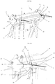
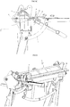
figure 1A représente une vue en perspective d'une plieuse conforme à un mode de réalisation préféré de l'invention en l'absence de flan, en position d'attente du tablier ; - la
figure 1B représente une vue partielle agrandie de lafigure 1A ; - la
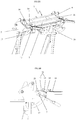
figure 2A représente une vue en perspective d'une plieuse conforme à l'invention en position active du tablier, au cours du pliage d'un flan ; - la
figure 2B représente une vue partielle agrandie de lafigure 2A ; - la
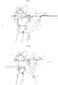
figure 3A représente une vue en perspective des butées avant et avant supplémentaire, du support, et des moyens d'empêchement de la butée avant dans une position correspondant à la position d'attente du tablier ; - la
figure 3B représente une vue de dessus de lafigure 3A ; - la
figure 3C représente une vue de côté des éléments de lafigure 3A ; - la
figure 4A représente une vue en perspective des butées avant et avant supplémentaire, du support, et des moyens d'empêchement de la butée avant dans une position correspondant à la position active du tablier ; - la
figure 4B représente une vue de côté des éléments de lafigure 4A ; - les
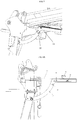
figures 5A à 5C représentent, sous forme de vues en coupe schématique, les positions respectives du tablier et de la butée avant au cours du pliage d'un flan ; - la
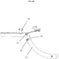
figure 6 représente une vue en perspective d'une plieuse équipée d'un dispositif de coupe du flan ; - la
figure 7 représente une vue partielle d'une plieuse en configuration inactive de la butée avant ; - les
figures 8A et8B représentent des vues partielles d'une plieuse illustrant une variante de réalisation de la butée avant.
- the
Figure 1A represents a perspective view of a folder according to a preferred embodiment of the invention in the absence of a blank, in waiting position of the deck; - the
Figure 1B represents an enlarged partial view of theFigure 1A ; - the
Figure 2A represents a perspective view of a folder according to the invention in the active position of the apron, during the folding of a blank; - the
Figure 2B represents an enlarged partial view of theFigure 2A ; - the
figure 3A represents a perspective view of the additional front and front stops, the support, and the means for preventing the front stop in a position corresponding to the waiting position of the apron; - the
figure 3B represents a top view of thefigure 3A ; - the
figure 3C represents a side view of the elements of thefigure 3A ; - the
Figure 4A represents a perspective view of the additional front and front stops, the support, and means for preventing the front stop in a position corresponding to the active position of the apron; - the
Figure 4B represents a side view of the elements of theFigure 4A ; - the
FIGS. 5A to 5C represent, in the form of schematic sectional views, the respective positions of the apron and the front stop during the folding of a blank; - the
figure 6 represents a perspective view of a folder equipped with a device for cutting the blank; - the
figure 7 represents a partial view of a folder in inactive configuration of the front stop; - the
Figures 8A and8B represent partial views of a folder illustrating an alternative embodiment of the front stop.
Comme mentionné ci-dessus, l'invention a pour objet une plieuse 1, notamment pour le pliage d'un flan 21 plat, tel qu'une tôle ou une feuille mince. Il doit être noté que cette plieuse 1 peut être également, de manière en soi connue, utilisée pour la coupe du flan, en particulier lorsqu'elle est équipée d'un dispositif 20 de coupe comme illustré à la
Cette plieuse 1 comprend un bâti 2 dont au moins une partie est formée par un sommier 3 délimitant, à la manière d'une table, un plateau 31 de réception du flan. Ce sommier 3 est, de manière en soi connue, un sommier fixe qui comprend, dans l'exemple représenté, un profilé creux de section transversale quadrangulaire et en pratique carrée avec, rapportés transversalement, chacun respectivement aux extrémités de ce profilé, deux flasques ou joues 4. Il comprend en outre, rapporté en saillie sur la face supérieure du profilé, une platine qui court sur toute la longueur de ce profilé d'un des deux flasques 4 à l'autre et qui, transversalement, s'étend en porte-à-faux le long de l'un des bords longitudinaux du profilé, en l'espèce son bord longitudinal avant.This
La face opposée de cette platine forme le plateau 31 de réception du flan, c'est-à-dire la partie utile du sommier sur laquelle doit être posé le flan à travailler.The opposite face of this plate forms the
Au sommier 3 ainsi constitué, est associé de manière usuelle un piètement 5 propre à son support. Ce piètement 5 relevant de l'homme de l'art et ne faisant pas partie en soi de la présente invention, il ne sera pas décrit plus en détail ici. Il suffit de constater, tel que représenté, qu'il peut être formé à la manière d'un chevalet de quatre pieds disposés par paires aux extrémités du sommier.To the
La plieuse 1 comprend également un presse-flan 6 monté mobile à rotation sur le sommier 3 entre une position d'ouverture dans laquelle il est écarté du sommier 3 pour l'introduction du flan 21 par son bord libre dit arrière entre sommier 3 et presse-flan 6 et une position de fermeture dans laquelle il est rapproché du sommier 3 et coopère avec ce dernier pour le maintien par pincement du flan 21.The
Dans cette position rapprochée du sommier, le presse-flan 6 vient, par son bec d'appui en applique sur le flan lui-même positionné en appui sur le plateau 31 de réception du sommier 3, pour un maintien par pincement du flan 21 entre presse-flan 6 et plateau 31 du sommier. Le montage à rotation du presse-flan sur le sommier s'opère par rotation du presse-flan autour d'un axe représenté en 25 à la
Généralement, pour ce montage à rotation, le presse-flan 6 est articulé à deux bielles parallèles qui, disposées respectivement chacune à ses extrémités, s'étendent transversalement et sont elles-mêmes chacune respectivement articulées au sommier directement, ou par deux biellettes.Generally, for this rotational mounting, the
La plieuse 1 comprend encore un tablier 7 adjacent au sommier 3 et couplé au bâti 2 par une liaison 8 pivot d'axe X, X'. Ce tablier 7, qui présente une partie 9 active formée par une surface sensiblement plane est, par l'intermédiaire de sa liaison 8 pivot, monté mobile à pivotement entre une position d'attente dans laquelle la partie 9 active du tablier 7 s'étend dans, ou sous et parallèlement, au plan passant par le plateau 31 du sommier 3 et une position active dans laquelle le tablier 7 s'étend au moins partiellement au-dessus du plan passant par le plateau 31 du sommier 3.The
Dans la forme de réalisation représentée, ce tablier 7 comporte, d'une part, un profilé qui s'étend sur toute la longueur du profilé du sommier, entre les flasques 4 de celui-ci, du côté de la face avant de ce profilé et auquel est attelé un quelconque levier 26 propre à en permettre la manoeuvre, et d'autre part, à la manière de la platine du sommier, une platine qui est rapportée, par exemple par soudage, sur le profilé, en s'étendant en porte-à-faux sur celui-ci.In the embodiment shown, this
La tranche supérieure de cette platine est, en position d'attente ou de repos du tablier à niveau avec le plateau 31 du sommier, ou s'étend sous et parallèlement au plan passant par le plateau 31 du sommier. Cette tranche supérieure de la platine forme la partie 9 active du tablier 7.The upper edge of this plate is, in the standby position or rest of the deck level with the
De manière en soi connue, pour son montage à rotation, ledit tablier 7 rotatif comprend à chacune de ses extrémités un tourillon engagé à pivotement dans un passage prévu à cet effet de manière complémentaire dans un flasque 4. Cet axe de rotation est représenté en X, X' aux figures. Le tourillon et le passage forment la liaison pivot représentée en 8 aux figures.In a manner known per se, for its rotational mounting, said
Dans l'exemple représenté, la plieuse comprend encore, associé à son sommier, un rail 24 de guidage du dispositif 20 de coupe le long du bec d'appui du presse-flan 6.In the example shown, the folder further comprises, associated with its bed base, a
La plieuse comprend enfin une butée 10 avant positionnée en avant de la face avant de la plieuse formée par le tablier. Cette butée 10 avant comprend une partie 11 active contre laquelle le bord libre avant, opposé au bord libre arrière, du flan 21 est apte à venir en appui à l'état positionné du flan 21 sur le plateau 31 du sommier 3.The folder finally comprises a
De manière caractéristique à l'invention, la butée 10 avant est au moins partiellement positionnable sur la trajectoire suivie par le tablier 7 lors de son passage de la position d'attente à la position active et est au moins, à l'état positionné sur ladite trajectoire, montée par l'intermédiaire d'une liaison 13 pivot, mobile à pivotement autour d'un axe sensiblement parallèle à l'axe XX' de pivotement du tablier 7 pour accompagner le déplacement du tablier lors de son passage de la position d'attente à la position active.In a manner characteristic of the invention, the
Dans l'exemple représenté, ladite butée 10 avant est montée mobile de manière libre à pivotement.In the example shown, said
Selon l'invention, la liaison 13 pivot pour le montage à pivotement de la butée 10 avant est disposée entre la butée 10 avant et un support 17, autre que le tablier 7. Ce support 17 est solidarisé ou solidarisable au bâti 2 et s'étend en porte-à-faux depuis le bâti 2.According to the invention, the
Grâce à ce montage de la butée 10 avant sur un support 17 solidarisé ou solidarisable au bâti 2 mais distinct du tablier 7, le tablier 7 peut, sur au moins une partie de sa course, être indépendant en déplacement de la butée 10 avant. La butée 10 avant peut ainsi, pour son déplacement, être heurtée par le tablier 7 qui l'entraîne ensuite en déplacement. La butée 10 avant, du fait de son montage libre à pivotement, peut également être indépendante en déplacement du tablier. La butée 10 avant et le tablier 7 sont donc configurés pour pouvoir être indépendants en déplacement.Thanks to this mounting of the front stop on a
La butée 10 avant comprend, outre la partie 11 active, une base 12 support de la partie 11 active le long de laquelle ladite partie 11 active est montée mobile à coulissement. Cette base 12, qui comprend une partie de la liaison 13 pivot entre butée 10 avant et reste de la plieuse 1 pour le montage à pivotement de ladite butée 10 avant, comprend en outre des graduations 18 aptes à coopérer avec un repère 15 porté par la partie 11 active pour un réglage en position de ladite partie 11 active.The
Cette base 12 de la butée avant affecte la forme d'un bras, le long duquel la partie 11 active est montée à coulissement. Ledit bras s'étend sensiblement orthogonalement à l'axe XX' de pivotement du tablier, avec au moins une partie du bras disposée dans l'espace laissé libre entre la façade du tablier 7 et la liaison 13 pivot du bras au reste de la plieuse.This
La partie 11 active est formée par une simple platine rapportée sur la face du dessus du bras. Cette platine comporte une lumière oblongue traversée par une vis de fixation de la platine au bras. Cette lumière permet un déplacement à coulissement de la partie 11 active de la butée 10 le long du bras, suivant une direction orthogonale à l'axe XX' de pivotement du tablier.The
La partie 11 active de la butée 10 avant est ainsi montée réglable en écartement par rapport à l'axe XX' de pivotement du tablier 7 par déplacement suivant une direction transversale audit axe XX'.The
La butée 10 avant comprend un organe 16 de roulement disposé, à l'état positionné de la butée 10 avant sur la trajectoire suivie par le tablier 7 lors du passage du tablier de la position d'attente à une position active, dans la zone de la butée 10 avant apte à venir en contact avec le tablier 7, lors du passage du tablier 7 de la position d'attente à la position active.The
Cet organe de roulement est disposé sur la face du dessous du bras, opposée à celle portant la partie active, au voisinage de l'extrémité libre du bras opposée à celle couplée au reste de la plieuse.This rolling member is disposed on the underside of the arm, opposite that carrying the active portion, in the vicinity of the free end of the arm opposite to that coupled to the rest of the folder.
Le support 17 de liaison de la butée 10 avant au bâti affecte quant à lui la forme d'un bras avec un premier tronçon de bras en forme générale d'arc de cercle à concavité tournée vers le tablier. Ce premier tronçon de bras est raccordé, à l'une de ses extrémités, par une liaison pivot au bâti, en un emplacement du bâti disposé sous le sommier et porte à l'autre extrémité de l'arc de cercle, une partie de la liaison 13 pivot de raccordement du support 17 à la butée 10 avant. Ce premier tronçon est prolongé par un deuxième tronçon rectiligne s'étendant, à l'état couplé du support 17 au bâti 2, en configuration d'utilisation du support 17, dans un plan parallèle ou confondu avec le plateau 31 du sommier 3. Le rôle de ce deuxième tronçon sera décrit ci-après.The
Dans l'exemple représenté, notamment aux
Pour le maintien dans la première configuration, ladite plieuse 1 comprend des moyens d'empêchement en déplacement à pivotement de la butée avant dans le sens d'un abaissement de la butée 10 avant au-delà d'une position initiale prédéterminée, correspondant à la position dans laquelle la partie 11 active de la butée 10 avant s'étend au moins partiellement dans un plan situé légèrement au-dessus du plan du plateau 31 du sommier 3 et correspondant au plan dans lequel le flan 21 est apte à s'étendre en position d'appui sur ledit plateau 31.For holding in the first configuration, said
Dans l'exemple représenté aux
De manière détaillée et illustrée aux
Le pion 22 est déplaçable à l'encontre du ressort, jusqu'à une position dans laquelle le contact d'appui entre doigt 23 et pion 22 est rompu, de sorte que la butée 10 avant est, sous l'effet de son propre poids, apte à s'abaisser par rotation autour de l'axe pivot de sa liaison 13 pivot de couplage au reste de la plieuse, comme l'illustre la
Pour un retour dans la première configuration, il suffit à nouveau de tirer sur le pion 22 à l'encontre du ressort et de relever la butée 10 avant par pivotement autour de son axe, jusqu'à ce que le doigt 23 passe le pion 22 pour permettre, par relâchement de la butée 10 avant, un appui du doigt 23 sur le pion 22.For a return to the first configuration, it is sufficient again to pull the
Dans ce mode de réalisation, le deuxième tronçon du support 17 tel que décrit ci-dessus est équipé d'une butée avant supplémentaire représentée en 19 aux figures. Cette butée avant 19 supplémentaire est, de manière similaire à la butée avant 10, formée d'une partie active et d'une base support constituée ici directement par le deuxième tronçon du support 17. La partie active de la butée avant supplémentaire est apte à coulisser le long de la base support suivant une direction orthogonale à l'axe XX' de pivotement du tablier.In this embodiment, the second section of the
La partie active de la butée 19 avant supplémentaire porte au moins deux repères 15 aptes à coopérer avec des graduations 18 portées par la base support pour un réglage en position de la partie active de la butée avant supplémentaire. Cette butée avant supplémentaire 19 est plus particulièrement utile pour la réalisation de plis éloignés du bord libre avant du flan par comparaison avec la butée 10 avant utile pour la réalisation de plis proches du bord libre avant du flan.The active part of the additional front stop 19 carries at least two
Dans l'exemple représenté, cette butée avant supplémentaire porte deux repères 15 positionnables en concordance avec les graduations 18 du support 17, lesdits repères 15 correspondant, l'un à la configuration de pliage, l'autre, à la configuration de coupe de la plieuse. En effet, et comme déjà mentionné ci-dessus, la plieuse peut comporter, de manière en soi connue, un dispositif 20 de coupe déplaçable le long du bâti 2 suivant une ligne parallèle à l'axe XX' de pivotement du tablier 7. La plieuse présente ainsi deux configurations d'utilisation, l'une de pliage par actionnement du tablier 7, l'autre de coupe par actionnement du dispositif 20 de coupe. Ces repères 15 servent, l'un pour une configuration d'utilisation, l'autre pour l'autre configuration d'utilisation de la plieuse.In the example shown, this additional front stop has two
On note que le dispositif 20 de coupe et la butée 19 avant supplémentaire sont inactifs dans la configuration dans laquelle la butée 10 avant s'étend sur la trajectoire suivie par le tablier 7 lors de son passage de la position d'attente à la position active.It should be noted that the cutting
Les
Dans ce mode de réalisation, la plieuse comprend à nouveau des moyens d'empêchement en déplacement à pivotement de la butée avant dans le sens d'un abaissement de la butée avant au-delà d'une position initiale prédéterminée correspondant à une position dans laquelle la partie 11 active de la butée 10 avant s'étend au moins partiellement dans un plan situé légèrement au-dessus du plan du plateau 31 du sommier 3. Toutefois, dans ce mode de réalisation, les moyens d'empêchement sont permanents et comprennent de manière similaire à ce qui a été décrit ci-dessus un doigt 23 monté solidaire en déplacement à pivotement de la butée 10 avant et un pion 22, qui coopèrent entre eux.In this embodiment, the folder again comprises means for preventing pivoting movement of the front stop in the direction of lowering the front stop beyond a predetermined initial position corresponding to a position in which the
Mais ces moyens d'empêchement comprennent en outre une rampe 27 portée par ledit support. Le doigt 23 coopère avec le pion 22 lorsque la butée avant est disposée sur la trajectoire suivie par le tablier lors du passage du tablier de la position d'attente à la position active, et avec ladite rampe 27 lorsque la butée avant est disposée en dehors de la trajectoire suivie par le tablier lors du passage du tablier de la position d'attente à la position active.But these means of prevention further comprise a
Dans les exemples illustrés ci-dessus, le support 17 de liaison de la butée 10 avant au bâti 2 est un support escamotable. L'escamotage est obtenu par déblocage de la liaison pivot reliant le support 17 au bâti. En position escamotée du support, la butée 10 avant s'étend au moins partiellement sous le sommier.In the examples illustrated above, the
Le fonctionnement d'une telle plieuse est tel que suit : le presse-flan 6 est en position écartée du sommier 3. La butée 10 avant est maintenue par ses moyens d'empêchement dans la position initiale représentée à la
Une fois le pliage opéré, le tablier et la butée 10 reviennent, sous l'effet de leur propre poids, dans leur position de départ correspondant, pour la butée 10 avant, à la position dans laquelle le doigt 23 de la butée 10 est en appui sur le pion 22 du support 17.Once folded, the apron and the
Une nouvelle opération de pliage peut être effectuée après enlèvement du flan et mise en place d'un nouveau flan. Si la position du pli doit être modifiée, il suffit de déplacer à coulissement la partie 11 active de la butée 10 avant le long de sa base 12 support. Si un pli éloigné du bord avant du flan doit être effectué, la butée 10 avant peut être escamotée par traction sur le pion 22 d'une distance suffisante pour éviter tout contact d'appui avec le doigt 23. La butée 10 avant s'abaisse et le relais peut être pris avec la butée 19 supplémentaire qui, du fait de son positionnement en dehors de la trajectoire suivie par le tablier lors de son passage de la position d'attente à la position active, est représentée non pivotante.A new folding operation can be performed after removing the blank and setting up a new blank. If the position of the fold is to be modified, it is sufficient to move the
Claims (12)
- A folder (1) for a flat blank (21), such as a thin sheet or foil, said folder (1) comprising:- a frame (2), at least part of which is formed by a backplate (3) delimiting, like a table, a receiving plate (31) for the blank,- a blank press (6) mounted moving relative to said backplate (3) between an open position, in which it is separated from the backplate (3) for the insertion of the blank (21) by its free edge, called rear, between the backplate (3) and the blank press (6), and a closed position, in which it is brought closer to the backplate (3), and cooperates with the latter, to hold the blank (21) by clamping,- an apron (7) adjacent to the backplate (3), and coupled to the frame (2) by a pivot link (8) with axis (XX'), said apron (7), which has an active part (9) formed by a substantially planar surface, being, by means of its pivot link (8), mounted pivotable between a standby position, in which the active part (9) of the apron (7) extends in, or below and parallel to, the plane passing through the plate (31) of the backplate (3) and an active position in which the apron (7) extends at least partially above the plane passing through the plate (31) of the backplate (3),- a so-called front stop (10) comprising an active part (11) against which the front free edge, opposite the rear free edge, of the blank (21) is able to bear in the state with the blank (21) positioned on the plate (31) of the backplate (3),the front stop (10) being at able to be at least partially positioned on the trajectory followed by the apron (7) when it goes from the standby position to the active position, characterized in that said stop (10) is, at least positioned on the trajectory followed by the apron (7) when it goes from the standby position to the active position, mounted, via a pivot link (13) pivotably around an axis substantially parallel to the pivot axis (XX') of the apron (7) and in that the pivot link (13) for the pivotable assembly of the front stop (10) is arranged between the front stop (10) and a separate support (17) of the apron (7).
- The folder (1) according to claim 1,
characterized in that the front stop (10) is mounted movably, preferably by pivotable movement, between a configuration in which it extends over the trajectory followed by the apron (7), during the passage of the apron (7), from the standby position to the active position, and a configuration in which it extends outside the trajectory followed by the apron (7), during the passage of the apron (7) from the standby position to the active position. - The folder (1) according to claim 2,
characterized in that the folder (1) comprises a device (20) for cutting the blank along at least one cutting line parallel to the pivot axis (XX') of the apron and/or an additional front stop (19), which are inactive in the configuration in which the front stop (10) extends over the trajectory followed by the apron (7) during the passage of the apron (7) from the standby position to the active position. - The folder (1) according to one of the preceding claims,
characterized in that said front stop (10) is, in the state positioned on the trajectory followed by the apron (7) during its passage from the standby position to the active position, mounted pivotably via said pivot link (13) around an axis substantially parallel to the pivot axis (XX') of the apron (7), from a so-called initial position in which the active part (11) of the front stop (10) extends at least partially in a plane, located slightly above the plane of the plate (31) of the backplate (3), and corresponding to the plane in which the blank (21) is able to extend in the bearing position on said plate (31), and in that the folder (1) comprises means (22, 23) for preventing the pivoting movement of the front stop (10) in the direction lowering the front stop (10) beyond said initial position. - The folder (1) according to claim 4,
characterized in that the prevention means (22, 23) are temporary prevention means, capable of being disabled, for the passage of the front stop (10) from a configuration in which it extends over the trajectory followed by the apron (7) during the passage of the apron (7) from the standby position to the active position, to a configuration in which it extends outside the trajectory followed by the apron (7) during the passage of the apron (7) from the standby position to the active position. - The folder (1) according to one of the preceding claims,
characterized in that at least the active part (11) of the front stop (10) is mounted with adjustable spacing relative to the pivot axis (XX') of the apron (7) by moving along a direction transverse, preferably orthogonal, to said axis (XX'). - The folder (1) according to one of the preceding claims,
characterized in that the front stop (10) comprises, aside from the active part (11), a support base (12) of the active part (11) along which said active part (11) is preferably mounted slidably, said base (12), which comprises a part of the pivot link (13) between front stop (10) and rest of the folder (1) for the pivoting assembly of said front stop (10), further comprising graduations (18) capable of cooperating with a reference mark (15) borne by the active part (11) for a position adjustment of said active part (11). - The folder (1) according to one of the preceding claims,
characterized in that the front stop (10) comprises a rolling member (16) arranged, in the state with the front stop (10) positioned on the trajectory followed by the apron (7) during the passage of the apron from the standby position to the active position, in the zone of the front stop (10) able to come into contact with the apron (7), during the passage of the apron (7) from the standby position to the active position. - The folder (1) according to one of the preceding claims,
characterized in that the support (17), which is secured or able to be secured to the frame (2), extends cantilevered from the frame (2). - The folder (1) according to one of the preceding claims, said folder (1) comprising a cutting device (20) movable along the frame (2) along a line parallel to the pivot axis (XX') of the apron (7), and having two usage configurations, one for folding, by actuating the apron (7), the other for cutting, by actuating the cutting device (20),
characterized in that the support (17) bears a series of graduations (18) to help position the front stop (10) or an additional front stop (19),
and in that the front stop (10) or the additional front stop (19), when it is present, bears two reference marks (15) able to be positioned matching the graduations (18) of the support (17), said reference marks (15) corresponding for one to the folding configuration, for the other to the cutting configuration of the folder (1). - The folder (1) according to one of the preceding claims,
characterized in that the front stop (10) is configured to be moved relative to the apron (7) without deformation. - The folder (1) according to one of the preceding claims,
characterized in that the front stop (10) is mounted via its movable pivot link (13) pivoting freely.
Applications Claiming Priority (1)
| Application Number | Priority Date | Filing Date | Title |
|---|---|---|---|
| FR1360597A FR3012352B1 (en) | 2013-10-30 | 2013-10-30 | FOLDER FOR FLAT FLAT |
Publications (2)
| Publication Number | Publication Date |
|---|---|
| EP2871006A1 EP2871006A1 (en) | 2015-05-13 |
| EP2871006B1 true EP2871006B1 (en) | 2019-02-06 |
Family
ID=49667506
Family Applications (1)
| Application Number | Title | Priority Date | Filing Date |
|---|---|---|---|
| EP14190038.1A Active EP2871006B1 (en) | 2013-10-30 | 2014-10-23 | Folder for flat blank |
Country Status (2)
| Country | Link |
|---|---|
| EP (1) | EP2871006B1 (en) |
| FR (1) | FR3012352B1 (en) |
Family Cites Families (6)
| Publication number | Priority date | Publication date | Assignee | Title |
|---|---|---|---|---|
| DE1927520A1 (en) * | 1969-05-30 | 1971-01-28 | Dornier Ag | Beding plates round small radii |
| FR2624037B1 (en) | 1987-12-04 | 1990-05-04 | Dimos Batiment | FOLDER |
| FR2630356A1 (en) * | 1988-04-20 | 1989-10-27 | Dimeco Alipresse | FOLDING MACHINE |
| DE4206417A1 (en) * | 1992-02-29 | 1993-09-02 | Edgar Griebel | SWIVEL BENDING MACHINE |
| FR2803792B1 (en) * | 2000-01-14 | 2002-08-16 | Dimos | FOLDER IN PARTICULAR FOR FLAT FLAN |
| US20060086168A1 (en) * | 2004-10-14 | 2006-04-27 | John Yoder | Sheet metal positioning assembly for use with a sheet metal brake |
-
2013
- 2013-10-30 FR FR1360597A patent/FR3012352B1/en not_active Expired - Fee Related
-
2014
- 2014-10-23 EP EP14190038.1A patent/EP2871006B1/en active Active
Non-Patent Citations (1)
| Title |
|---|
| None * |
Also Published As
| Publication number | Publication date |
|---|---|
| FR3012352B1 (en) | 2016-04-15 |
| EP2871006A1 (en) | 2015-05-13 |
| FR3012352A1 (en) | 2015-05-01 |
Similar Documents
| Publication | Publication Date | Title |
|---|---|---|
| EP1946897B1 (en) | Knife with automatically retractable blade | |
| EP3345660B1 (en) | Abutment of a binding device of a boot | |
| EP0242309B1 (en) | Bending press with pivoting beam | |
| EP2871006B1 (en) | Folder for flat blank | |
| FR2939347A1 (en) | Staple remover for use with pocket stapler, has jaw movable by pivoting between usage position, in which jaw is projected toward rear side, and retracted non-usage position in which jaw is placed in housing hollowed under stapler base | |
| EP1690619B1 (en) | Cutting table for metal sheets | |
| EP0485797A1 (en) | Buckling folder, in three parts | |
| CA2863493A1 (en) | Mounting frame for a vehicle door | |
| FR3005589A1 (en) | MACHINE FOR FOLDING A FLAN | |
| FR2545463A1 (en) | TAPE APPLIANCE APPARATUS | |
| EP1261477B1 (en) | Brake in particular for flat blank | |
| EP2240355B1 (en) | Carriage for a railroad track-laying and maintenance machine | |
| EP2956278B1 (en) | Utility kinfe with automatically retractable blade | |
| EP0884218A1 (en) | Movable foot step for a vehicle | |
| EP1274538B1 (en) | Centring and clamping control tool | |
| EP3202696B1 (en) | Retractable stopper device for a vehicle loading and/or unloading dock | |
| FR2925381A1 (en) | Punching tool e.g. stapler, for cardboard plate, has swing bar mounted between actuating cover and punch, where bar has rear end cooperating with tripper mounted under cover and front end connected permanently to punch | |
| EP1026363B1 (en) | Security device against the lifting of roller shutters | |
| FR2606965A1 (en) | Film retention device for an unrolling and seeding machine | |
| FR2483269A1 (en) | Reel unwinding starter and guide - has starting head passing under reel end actuated by hydraulic jack mounted on frame | |
| FR2789436A1 (en) | Anti-winding safety device for roller shutter has cheek web integral to shutter winding shaft with connecting rod pivoting between deployed and retracted positions | |
| FR3120216A1 (en) | Three-position retainer and associated trim element | |
| FR2708437A1 (en) | Case for a stick of cosmetic, pharmaceutical or similar pasty product | |
| FR3072884A1 (en) | FASTENING DEVICE FOR FIXING A SHOE | |
| FR2505223A1 (en) | Table for cutting sheet metal - uses fixed lower and upper movable beam in pin jointed parallelogram to clamp sheet edge in path of cutter |
Legal Events
| Date | Code | Title | Description |
|---|---|---|---|
| PUAI | Public reference made under article 153(3) epc to a published international application that has entered the european phase |
Free format text: ORIGINAL CODE: 0009012 |
|
| 17P | Request for examination filed |
Effective date: 20141023 |
|
| AK | Designated contracting states |
Kind code of ref document: A1 Designated state(s): AL AT BE BG CH CY CZ DE DK EE ES FI FR GB GR HR HU IE IS IT LI LT LU LV MC MK MT NL NO PL PT RO RS SE SI SK SM TR |
|
| AX | Request for extension of the european patent |
Extension state: BA ME |
|
| R17P | Request for examination filed (corrected) |
Effective date: 20150922 |
|
| RBV | Designated contracting states (corrected) |
Designated state(s): AL AT BE BG CH CY CZ DE DK EE ES FI FR GB GR HR HU IE IS IT LI LT LU LV MC MK MT NL NO PL PT RO RS SE SI SK SM TR |
|
| GRAP | Despatch of communication of intention to grant a patent |
Free format text: ORIGINAL CODE: EPIDOSNIGR1 |
|
| STAA | Information on the status of an ep patent application or granted ep patent |
Free format text: STATUS: GRANT OF PATENT IS INTENDED |
|
| INTG | Intention to grant announced |
Effective date: 20181026 |
|
| GRAS | Grant fee paid |
Free format text: ORIGINAL CODE: EPIDOSNIGR3 |
|
| GRAA | (expected) grant |
Free format text: ORIGINAL CODE: 0009210 |
|
| STAA | Information on the status of an ep patent application or granted ep patent |
Free format text: STATUS: THE PATENT HAS BEEN GRANTED |
|
| AK | Designated contracting states |
Kind code of ref document: B1 Designated state(s): AL AT BE BG CH CY CZ DE DK EE ES FI FR GB GR HR HU IE IS IT LI LT LU LV MC MK MT NL NO PL PT RO RS SE SI SK SM TR |
|
| REG | Reference to a national code |
Ref country code: GB Ref legal event code: FG4D Free format text: NOT ENGLISH |
|
| REG | Reference to a national code |
Ref country code: CH Ref legal event code: EP Ref country code: AT Ref legal event code: REF Ref document number: 1094540 Country of ref document: AT Kind code of ref document: T Effective date: 20190215 |
|
| REG | Reference to a national code |
Ref country code: IE Ref legal event code: FG4D Free format text: LANGUAGE OF EP DOCUMENT: FRENCH |
|
| REG | Reference to a national code |
Ref country code: DE Ref legal event code: R096 Ref document number: 602014040678 Country of ref document: DE |
|
| REG | Reference to a national code |
Ref country code: NL Ref legal event code: MP Effective date: 20190206 |
|
| REG | Reference to a national code |
Ref country code: LT Ref legal event code: MG4D |
|
| PG25 | Lapsed in a contracting state [announced via postgrant information from national office to epo] |
Ref country code: PT Free format text: LAPSE BECAUSE OF FAILURE TO SUBMIT A TRANSLATION OF THE DESCRIPTION OR TO PAY THE FEE WITHIN THE PRESCRIBED TIME-LIMIT Effective date: 20190606 Ref country code: LT Free format text: LAPSE BECAUSE OF FAILURE TO SUBMIT A TRANSLATION OF THE DESCRIPTION OR TO PAY THE FEE WITHIN THE PRESCRIBED TIME-LIMIT Effective date: 20190206 Ref country code: NL Free format text: LAPSE BECAUSE OF FAILURE TO SUBMIT A TRANSLATION OF THE DESCRIPTION OR TO PAY THE FEE WITHIN THE PRESCRIBED TIME-LIMIT Effective date: 20190206 Ref country code: FI Free format text: LAPSE BECAUSE OF FAILURE TO SUBMIT A TRANSLATION OF THE DESCRIPTION OR TO PAY THE FEE WITHIN THE PRESCRIBED TIME-LIMIT Effective date: 20190206 Ref country code: NO Free format text: LAPSE BECAUSE OF FAILURE TO SUBMIT A TRANSLATION OF THE DESCRIPTION OR TO PAY THE FEE WITHIN THE PRESCRIBED TIME-LIMIT Effective date: 20190506 Ref country code: SE Free format text: LAPSE BECAUSE OF FAILURE TO SUBMIT A TRANSLATION OF THE DESCRIPTION OR TO PAY THE FEE WITHIN THE PRESCRIBED TIME-LIMIT Effective date: 20190206 |
|
| REG | Reference to a national code |
Ref country code: AT Ref legal event code: MK05 Ref document number: 1094540 Country of ref document: AT Kind code of ref document: T Effective date: 20190206 |
|
| PG25 | Lapsed in a contracting state [announced via postgrant information from national office to epo] |
Ref country code: BG Free format text: LAPSE BECAUSE OF FAILURE TO SUBMIT A TRANSLATION OF THE DESCRIPTION OR TO PAY THE FEE WITHIN THE PRESCRIBED TIME-LIMIT Effective date: 20190506 Ref country code: IS Free format text: LAPSE BECAUSE OF FAILURE TO SUBMIT A TRANSLATION OF THE DESCRIPTION OR TO PAY THE FEE WITHIN THE PRESCRIBED TIME-LIMIT Effective date: 20190606 Ref country code: GR Free format text: LAPSE BECAUSE OF FAILURE TO SUBMIT A TRANSLATION OF THE DESCRIPTION OR TO PAY THE FEE WITHIN THE PRESCRIBED TIME-LIMIT Effective date: 20190507 Ref country code: RS Free format text: LAPSE BECAUSE OF FAILURE TO SUBMIT A TRANSLATION OF THE DESCRIPTION OR TO PAY THE FEE WITHIN THE PRESCRIBED TIME-LIMIT Effective date: 20190206 Ref country code: LV Free format text: LAPSE BECAUSE OF FAILURE TO SUBMIT A TRANSLATION OF THE DESCRIPTION OR TO PAY THE FEE WITHIN THE PRESCRIBED TIME-LIMIT Effective date: 20190206 Ref country code: HR Free format text: LAPSE BECAUSE OF FAILURE TO SUBMIT A TRANSLATION OF THE DESCRIPTION OR TO PAY THE FEE WITHIN THE PRESCRIBED TIME-LIMIT Effective date: 20190206 |
|
| PG25 | Lapsed in a contracting state [announced via postgrant information from national office to epo] |
Ref country code: CZ Free format text: LAPSE BECAUSE OF FAILURE TO SUBMIT A TRANSLATION OF THE DESCRIPTION OR TO PAY THE FEE WITHIN THE PRESCRIBED TIME-LIMIT Effective date: 20190206 Ref country code: RO Free format text: LAPSE BECAUSE OF FAILURE TO SUBMIT A TRANSLATION OF THE DESCRIPTION OR TO PAY THE FEE WITHIN THE PRESCRIBED TIME-LIMIT Effective date: 20190206 Ref country code: ES Free format text: LAPSE BECAUSE OF FAILURE TO SUBMIT A TRANSLATION OF THE DESCRIPTION OR TO PAY THE FEE WITHIN THE PRESCRIBED TIME-LIMIT Effective date: 20190206 Ref country code: AL Free format text: LAPSE BECAUSE OF FAILURE TO SUBMIT A TRANSLATION OF THE DESCRIPTION OR TO PAY THE FEE WITHIN THE PRESCRIBED TIME-LIMIT Effective date: 20190206 Ref country code: SK Free format text: LAPSE BECAUSE OF FAILURE TO SUBMIT A TRANSLATION OF THE DESCRIPTION OR TO PAY THE FEE WITHIN THE PRESCRIBED TIME-LIMIT Effective date: 20190206 Ref country code: DK Free format text: LAPSE BECAUSE OF FAILURE TO SUBMIT A TRANSLATION OF THE DESCRIPTION OR TO PAY THE FEE WITHIN THE PRESCRIBED TIME-LIMIT Effective date: 20190206 Ref country code: IT Free format text: LAPSE BECAUSE OF FAILURE TO SUBMIT A TRANSLATION OF THE DESCRIPTION OR TO PAY THE FEE WITHIN THE PRESCRIBED TIME-LIMIT Effective date: 20190206 Ref country code: EE Free format text: LAPSE BECAUSE OF FAILURE TO SUBMIT A TRANSLATION OF THE DESCRIPTION OR TO PAY THE FEE WITHIN THE PRESCRIBED TIME-LIMIT Effective date: 20190206 |
|
| REG | Reference to a national code |
Ref country code: DE Ref legal event code: R097 Ref document number: 602014040678 Country of ref document: DE |
|
| PG25 | Lapsed in a contracting state [announced via postgrant information from national office to epo] |
Ref country code: SM Free format text: LAPSE BECAUSE OF FAILURE TO SUBMIT A TRANSLATION OF THE DESCRIPTION OR TO PAY THE FEE WITHIN THE PRESCRIBED TIME-LIMIT Effective date: 20190206 Ref country code: PL Free format text: LAPSE BECAUSE OF FAILURE TO SUBMIT A TRANSLATION OF THE DESCRIPTION OR TO PAY THE FEE WITHIN THE PRESCRIBED TIME-LIMIT Effective date: 20190206 |
|
| PLBE | No opposition filed within time limit |
Free format text: ORIGINAL CODE: 0009261 |
|
| STAA | Information on the status of an ep patent application or granted ep patent |
Free format text: STATUS: NO OPPOSITION FILED WITHIN TIME LIMIT |
|
| PG25 | Lapsed in a contracting state [announced via postgrant information from national office to epo] |
Ref country code: AT Free format text: LAPSE BECAUSE OF FAILURE TO SUBMIT A TRANSLATION OF THE DESCRIPTION OR TO PAY THE FEE WITHIN THE PRESCRIBED TIME-LIMIT Effective date: 20190206 |
|
| 26N | No opposition filed |
Effective date: 20191107 |
|
| PG25 | Lapsed in a contracting state [announced via postgrant information from national office to epo] |
Ref country code: SI Free format text: LAPSE BECAUSE OF FAILURE TO SUBMIT A TRANSLATION OF THE DESCRIPTION OR TO PAY THE FEE WITHIN THE PRESCRIBED TIME-LIMIT Effective date: 20190206 |
|
| PG25 | Lapsed in a contracting state [announced via postgrant information from national office to epo] |
Ref country code: TR Free format text: LAPSE BECAUSE OF FAILURE TO SUBMIT A TRANSLATION OF THE DESCRIPTION OR TO PAY THE FEE WITHIN THE PRESCRIBED TIME-LIMIT Effective date: 20190206 |
|
| PG25 | Lapsed in a contracting state [announced via postgrant information from national office to epo] |
Ref country code: MC Free format text: LAPSE BECAUSE OF FAILURE TO SUBMIT A TRANSLATION OF THE DESCRIPTION OR TO PAY THE FEE WITHIN THE PRESCRIBED TIME-LIMIT Effective date: 20190206 |
|
| REG | Reference to a national code |
Ref country code: CH Ref legal event code: PL |
|
| PG25 | Lapsed in a contracting state [announced via postgrant information from national office to epo] |
Ref country code: LU Free format text: LAPSE BECAUSE OF NON-PAYMENT OF DUE FEES Effective date: 20191023 Ref country code: CH Free format text: LAPSE BECAUSE OF NON-PAYMENT OF DUE FEES Effective date: 20191031 Ref country code: LI Free format text: LAPSE BECAUSE OF NON-PAYMENT OF DUE FEES Effective date: 20191031 |
|
| REG | Reference to a national code |
Ref country code: BE Ref legal event code: MM Effective date: 20191031 |
|
| PG25 | Lapsed in a contracting state [announced via postgrant information from national office to epo] |
Ref country code: BE Free format text: LAPSE BECAUSE OF NON-PAYMENT OF DUE FEES Effective date: 20191031 |
|
| GBPC | Gb: european patent ceased through non-payment of renewal fee |
Effective date: 20191023 |
|
| PG25 | Lapsed in a contracting state [announced via postgrant information from national office to epo] |
Ref country code: IE Free format text: LAPSE BECAUSE OF NON-PAYMENT OF DUE FEES Effective date: 20191023 Ref country code: GB Free format text: LAPSE BECAUSE OF NON-PAYMENT OF DUE FEES Effective date: 20191023 |
|
| PG25 | Lapsed in a contracting state [announced via postgrant information from national office to epo] |
Ref country code: CY Free format text: LAPSE BECAUSE OF FAILURE TO SUBMIT A TRANSLATION OF THE DESCRIPTION OR TO PAY THE FEE WITHIN THE PRESCRIBED TIME-LIMIT Effective date: 20190206 |
|
| REG | Reference to a national code |
Ref country code: DE Ref legal event code: R081 Ref document number: 602014040678 Country of ref document: DE Owner name: DIMOS, FR Free format text: FORMER OWNER: G. PARTICIPATIONS, ANCENIS, FR |
|
| PG25 | Lapsed in a contracting state [announced via postgrant information from national office to epo] |
Ref country code: HU Free format text: LAPSE BECAUSE OF FAILURE TO SUBMIT A TRANSLATION OF THE DESCRIPTION OR TO PAY THE FEE WITHIN THE PRESCRIBED TIME-LIMIT; INVALID AB INITIO Effective date: 20141023 Ref country code: MT Free format text: LAPSE BECAUSE OF FAILURE TO SUBMIT A TRANSLATION OF THE DESCRIPTION OR TO PAY THE FEE WITHIN THE PRESCRIBED TIME-LIMIT Effective date: 20190206 |
|
| PG25 | Lapsed in a contracting state [announced via postgrant information from national office to epo] |
Ref country code: MK Free format text: LAPSE BECAUSE OF FAILURE TO SUBMIT A TRANSLATION OF THE DESCRIPTION OR TO PAY THE FEE WITHIN THE PRESCRIBED TIME-LIMIT Effective date: 20190206 |
|
| PGFP | Annual fee paid to national office [announced via postgrant information from national office to epo] |
Ref country code: FR Payment date: 20231025 Year of fee payment: 10 Ref country code: DE Payment date: 20231020 Year of fee payment: 10 |