EP2869966B1 - Elektrowerkzeug - Google Patents
Elektrowerkzeug Download PDFInfo
- Publication number
- EP2869966B1 EP2869966B1 EP13728175.4A EP13728175A EP2869966B1 EP 2869966 B1 EP2869966 B1 EP 2869966B1 EP 13728175 A EP13728175 A EP 13728175A EP 2869966 B1 EP2869966 B1 EP 2869966B1
- Authority
- EP
- European Patent Office
- Prior art keywords
- gear
- power tool
- bearing
- space
- hand held
- Prior art date
- Legal status (The legal status is an assumption and is not a legal conclusion. Google has not performed a legal analysis and makes no representation as to the accuracy of the status listed.)
- Active
Links
Images

Classifications
-
- B—PERFORMING OPERATIONS; TRANSPORTING
- B24—GRINDING; POLISHING
- B24B—MACHINES, DEVICES, OR PROCESSES FOR GRINDING OR POLISHING; DRESSING OR CONDITIONING OF ABRADING SURFACES; FEEDING OF GRINDING, POLISHING, OR LAPPING AGENTS
- B24B23/00—Portable grinding machines, e.g. hand-guided; Accessories therefor
- B24B23/02—Portable grinding machines, e.g. hand-guided; Accessories therefor with rotating grinding tools; Accessories therefor
- B24B23/026—Fluid driven
-
- B—PERFORMING OPERATIONS; TRANSPORTING
- B24—GRINDING; POLISHING
- B24B—MACHINES, DEVICES, OR PROCESSES FOR GRINDING OR POLISHING; DRESSING OR CONDITIONING OF ABRADING SURFACES; FEEDING OF GRINDING, POLISHING, OR LAPPING AGENTS
- B24B47/00—Drives or gearings; Equipment therefor
- B24B47/10—Drives or gearings; Equipment therefor for rotating or reciprocating working-spindles carrying grinding wheels or workpieces
-
- B—PERFORMING OPERATIONS; TRANSPORTING
- B25—HAND TOOLS; PORTABLE POWER-DRIVEN TOOLS; MANIPULATORS
- B25F—COMBINATION OR MULTI-PURPOSE TOOLS NOT OTHERWISE PROVIDED FOR; DETAILS OR COMPONENTS OF PORTABLE POWER-DRIVEN TOOLS NOT PARTICULARLY RELATED TO THE OPERATIONS PERFORMED AND NOT OTHERWISE PROVIDED FOR
- B25F5/00—Details or components of portable power-driven tools not particularly related to the operations performed and not otherwise provided for
- B25F5/001—Gearings, speed selectors, clutches or the like specially adapted for rotary tools
Definitions
- the invention relates to a power tool such as a grinder. Specifically, the invention relates to a power tool with an improved fluid sealing arrangement between a gear space and a motor room.
- a conventional power tool such as e.g. a grinder, comprises a bevel gear that is provided to redirect the rotational movement from a pinion shaft rotating around a first axis to an output shaft rotating around a second axis that is substantially perpendicular to the first axis.
- a tool is known from e.g. EP 0 261 374 A1 , US 2012/0157257 A1 and EP 1 327 497 B1 .
- the bevel gear is continuously in need of lubrication.
- a lubrication fluid is arranged in a fluid tight gear space that surrounds the bevel gear.
- the gear space is a fluid tight space that is delimited by a gear housing.
- the gear housing is normally formed of several parts and inter alia includes two sealings, one axial sealing around the pinion shaft and one radial sealing around the output shaft. Further, both the output shaft and the pinion shaft are supported by bearings, which preferably are located as close as possible to the bevel gear.
- a problem that arises in conventional power tools of this type is that especially the axial sealing around the pinion shaft is degenerated over time, such that lubrication fluid may eventually leak into the motor room and/or pass out to the area known as the reception area, e.g. the area immediately surrounding the power tool and the operator.
- the sealing surrounding the pinion shaft is specifically crucial as the pinion shaft rotates about five to ten times faster than the output shaft, depending on the gear ratio of the bevel gear.
- An object of the invention is to provide a power tool with an improved reliability. This object is achieved by the invention according to the independent claims.
- the invention relates to a hand held power tool as defined in claim 1.
- An advantage of the invention with respect to a conventional power tool of the prior art is that the sealing is continuously provided with the lubrication fluid that surrounds the bevel gear and that is present in the fluid tight housing that delimits the gear space around the bevel gear.
- the provision of lubrication to the sealing prevents burning and maintains the function of the sealing throughout its operational lifetime. If there was no opening to connect the gear space to the confined space between the fluid tight axial sealing and the bearing, the axial sealing around the pinion shaft may eventually dry out such that its function would slowly degrade.
- the bearing that support the pinion shaft inside of the sealing 20.
- This is however an inferior solution with regard to the mounting of the pinion shaft.
- the bearing may be located as close as possible to the pinion gear without negatively affecting the function of the sealing.
- the bearing is supported by a hollow support member that is arranged outside the pinion shaft, wherein the confined space of the gear space is axially delimited by the bearing on one side and, on the other side and farther away from the bevel gear than the bearing, by the fluid tight axial sealing, and radially by the hollow support member.
- the at least one fluid conveying opening is arranged as at least one track between the bearing and the hollow support member.
- the at least one fluid conveying opening may be arranged as at least one channel through the hollow support member.
- the bearing is supported by the gear housing, and wherein the at least one fluid conveying opening is arranged as at least one track along the interface between the bearing and the gear housing.
- the hand held power tool may preferably be a grinder, and specifically it may be a pneumatic grinder.
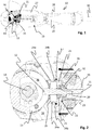
- the power tool 10 comprises a motor room 19 and a gear space 26, which are housed in a common outer housing 27. Further the power tool 10 comprises a handle 28, on which a lever 29 is arranged for controlling the air supply to a motor arranged inside the motor room 19. The handle is connected to an air supply hose 30 for supply of pressurized air to the motor.
- the gear space 26 includes a bevel gear 12, 13, in which a pinion shaft 11 is connected via a pinion gear 12 to a crown gear 13.
- FIG. 2 shows a close up of the part of the power tool 10 to which the invention relates.
- a pinion shaft 11 is arranged to transmit the motor output from the motor inside a motor room 19 to the bevel gear 12, 13, which is located inside a gear housing 18 that delimits the gear space 26.
- the bevel gear comprises a pinion gear 12, which constitutes the end part of the pinion shaft 11, and a crown gear 13, which is connected to an output shaft 14.
- the bevel gear transmits the rotation of the pinion shaft 11 to the output shaft 14, which is arranged orthogonally with respect to the pinion shaft 11.
- the bevel gear normally gears down the rotation of the pinion shaft 11 about five to ten times depending on the gear ratio. Hence, the output shaft normally rotates at a lower speed, but at a correspondingly higher torque level.
- a bearing 15 is arranged around the pinion shaft 11.
- the bearing 15 is kept at place by means of the gear housing 18 and a hollow support member 16.
- the hollow support member 16 is in the shown embodiment arranged to provide a fluid tight connection between the gear housing 18 and the motor room 19.
- a lubrication fluid is arranged inside the gear space 26 defined inter alia by the gear housing 18, which fluid must not be allowed into the motor room 19. Therefore, the connection between the gear housing 18 and the hollow support member 16 includes a first static sealing 17, e.g. in the form of an O-ring.
- the fluid tight connection between the hollow support member 16 and the motor room 19 is more complicated, due to the fact that this connection involves a moving part, i.e. the pinion shaft 11.
- the pinion shaft 11 is arranged to rotate at about 65 000 rpm, and the output shaft 14 is arranged to rotate at about 8 500 rpm. A rotation of that magnitude puts high demands on the fluid tightening used.
- the fluid tightening consists of an axial sealing 20 that comprises a first sealing part 21 that is fixedly attached the pinion shaft 11, so as to rotate with the pinion shaft 11.
- a second sealing part 22 is arranged to seal against the first sealing part 21.
- the first and second sealing parts 21, 22 comprises mutually opposed sealing surfaces of high precision that are arranged to rotate with respect to each other.
- the second sealing part 22 is provided with a spring (not shown) that is arranged in a spring seat 23 in the hollow support member 16 and acts towards the first sealing part 21. Further, a second static sealing 32, e.g. in the form of an O-ring, is arranged to seal between the second sealing part 22 and the hollow support member 16.
- the crucial sealing is the sealing between the first and second sealing parts 21, 22. This is due to the very high rotational speed of the pinion shaft 11 and the first sealing part 21 with respect to the radially fixed second sealing part 22.
- the axial sealing is completed by means of a film of lubrication fluid that is formed between the first and second sealing parts 21, 22 from the lubrication fluid provided inside the gear housing 18.
- the lubrication fluid is necessary for the well function of the axial sealing 20, and functions both to lower the friction and to cool the sealing. If there is not enough lubrication fluid the sealing may dry out and burn such that the sealing function will degrade and eventually be lost.
- the bearing 15 is held at place by the gear housing 18 and the hollow support member 16.
- the hollow support member 16 delimits a confined space 25 within the gear space 26 that is defined by the gear housing 18. This confined space 25 is axially delimited by the bearing 15 on one side and by the fluid tight axial sealing 20 on the other side, and radially by the hollow support member 16.
- the invention is related to the provision of lubrication fluid to the axial sealing 20.
- at least one opening 24a and 24b is provided between the gear space 26 and the confined space 25 surrounding the axial sealing 20.
- four such openings 24a, 24b are arranged 90 degrees apart around the bearing 15, whereof two are visible in figure 2 ; one above and one below the bearing 15.
- the openings 24a, 24b consist of channels in the interface between the bearing 15 and the hollow support member 16 and in the interface between the bearing 15 and the gear housing 18.
- These two interconnected openings 24a and 24b together form one continuous opening, in the form of a channel.
- the channels are formed as axial recesses along the interior surface of the hollow support member 16 and the gear housing 18.
- openings 24a, 24b solve two problems that were apparent in the prior art. Firstly, the openings 24a, 24b guarantees that there is a continuous flow of lubrication fluid to the axial sealing 20, such that the friction between the first and second sealing parts 21, 22 is kept as low as possible and such that the sealing 20 is continuously cooled. Secondly, the openings 24a, 24b provides for the possibility to even out the pressure between the confined space 25 around the axial sealing and the rest of the gear space 26.
- the lubrication fluid could only travel from the confined space 25 around the axial sealing to the rest of the gear space 26 and vice versa through the bearing 15. This has proven to not always be sufficient in order to provide necessary lubrication and cooling. Further, as a consequence of the friction in the axial sealing the temperature, and thus the pressure, may increase in the confined space around the axial sealing. This increased pressure gives rise to a force that acts on the second sealing part 22, which may cause the second sealing part 22 to move away from contact with the first sealing part 21, such that a fluid emitting gap may be formed there between. When such a gap is formed an undesired leakage into the motor room 19 may occur.
- the openings 24a, 24b will prevent leakage. It is worth noting that these openings may be arranged in other ways. For instance they may be achieved as through holes through the hollow support member 16. In another not shown embodiment the hollow support member 16 may be dispensed with, wherein the gear housing may be sealed directly to the motor room housing. In such an embodiment the bearing 15 may also be held at place by the gear housing 18 and/or the motor room housing, wherein the openings may be achieved as channels between the connection of the bearing 15 to the gear housing and/or the motor room housing.
- FIG 3 a side view of a power tool 10 according to an embodiment of the invention is shown.
- the power tool includes a handle 28 with a lever 29 arranged to control the air supply.
- An air supply hose 30 is connected to the back end of the handle 28.
- a support handle 31 is arranged on the left front end of the power tool 10.
- the gear housing 18 is in contact with the bearing 15. This of course depends on where the section is taken.
- the shown embodiment includes four openings 24a and 24b, which are located about 90 degrees apart around the bearing 15, and which are provided as tracks between both the gear housing 18 and the bearing 15 and between the hollow support member 16 and the bearing 15
Landscapes
- Engineering & Computer Science (AREA)
- Mechanical Engineering (AREA)
- Gear Transmission (AREA)
- Finish Polishing, Edge Sharpening, And Grinding By Specific Grinding Devices (AREA)
- General Details Of Gearings (AREA)
Claims (6)
- Handgeführtes Elektrowerkzeug (10), wobei das Elektrowerkzeug umfasst:- einen Motorraum (19), der einen Motor aufnimmt, der eine Motorabtriebswelle antreibt;- ein Kegelrad (12, 13), das ein mit einem Kronenrad (13) verbundenes Ritzelrad (12) umfasst, wobei das Ritzelrad (12) mit einer Ritzelwelle (11) verbunden ist, die mit der Motorabtriebswelle antriebsverbunden ist, und das Kronenrad (13) mit einer Werkzeughaltewelle antriebsverbunden ist;- ein Getriebegehäuse (18), das mindestens teilweise einen fluiddichten Getrieberaum (26) um das Kegelrad (12, 13) herum abgrenzt;- ein Lager (15), das um die Ritzelwelle (11) herum angeordnet ist, in der Nähe des Ritzelrades (12), wobei das Lager (15) einen begrenzten Raum (25) um die Ritzelwelle (11) herum von dem Rest des Getrieberaums (26) abgrenzt; und- eine fluiddichte Axialdichtung (20), die um die Ritzelwelle (11) herum innerhalb des begrenzten Raums (25) des Getrieberaums (26) angeordnet ist, wobei die Dichtung (20) den Getrieberaum (26) von dem Motorraum (19) abdichtet, wobei mindestens eine fluidführende Öffnung (24a, 24b) angeordnet ist, um den begrenzten Raum (25) des Getrieberaums (26) in Fluidkontakt mit dem Rest des Getrieberaums (26) zu bringen,wobei das Lager (15) von einem hohlen Trägerelement (16) gestützt wird, das außerhalb der Ritzelwelle (11) angeordnet ist, und wobei der begrenzte Raum (25) des Getrieberaums axial durch das Lager (15) auf einer Seite und auf der anderen Seite und weiter von dem Kegelrad (12, 13) entfernt als das Lager (15), durch die fluiddichte Axialdichtung (20) und radial durch das hohle Stützelement (16) abgegrenzt ist.
- Handgeführtes Elektrowerkzeug nach Anspruch 1, wobei die mindestens eine fluidführende Öffnung (24b) als mindestens eine Bahn zwischen dem Lager (15) und dem hohlen Stützelement (16) angeordnet ist.
- Handgeführtes Elektrowerkzeug (10) nach Anspruch 1, wobei die mindestens eine fluidführende Öffnung als mindestens ein Kanal durch das hohle Stützelement (16) angeordnet ist.
- Handgeführtes Elektrowerkzeug (10) nach Anspruch 1, wobei das Lager (15) durch das Getriebegehäuse (18) gestützt ist und wobei die mindestens eine fluidführende Öffnung (24a) als mindestens eine Bahn entlang der Schnittstelle zwischen dem Lager (15) und dem Getriebegehäuse 818) angeordnet ist.
- Handgeführtes Elektrowerkzeug (10) nach einem der vorstehenden Ansprüche, wobei das handgeführte Elektrowerkzeug (10) ein Schleifgerät ist.
- Handgeführtes Elektrowerkzeug (10) nach Anspruch 5, wobei das handgeführte Elektrowerkzeug (10) ein pneumatisches Schleifgerät ist.
Applications Claiming Priority (2)
| Application Number | Priority Date | Filing Date | Title |
|---|---|---|---|
| SE1250756 | 2012-07-03 | ||
| PCT/EP2013/061947 WO2014005800A1 (en) | 2012-07-03 | 2013-06-11 | Power tool |
Publications (2)
| Publication Number | Publication Date |
|---|---|
| EP2869966A1 EP2869966A1 (de) | 2015-05-13 |
| EP2869966B1 true EP2869966B1 (de) | 2018-08-08 |
Family
ID=48607255
Family Applications (1)
| Application Number | Title | Priority Date | Filing Date |
|---|---|---|---|
| EP13728175.4A Active EP2869966B1 (de) | 2012-07-03 | 2013-06-11 | Elektrowerkzeug |
Country Status (5)
| Country | Link |
|---|---|
| US (1) | US9314896B2 (de) |
| EP (1) | EP2869966B1 (de) |
| JP (1) | JP6217051B2 (de) |
| CN (1) | CN104395038B (de) |
| WO (1) | WO2014005800A1 (de) |
Families Citing this family (5)
| Publication number | Priority date | Publication date | Assignee | Title |
|---|---|---|---|---|
| DE102014105842A1 (de) * | 2014-04-25 | 2015-10-29 | C. & E. Fein Gmbh | Handgeführte Werkzeugmaschine mit ergonomischem Griffteil |
| DE102016216794A1 (de) * | 2015-09-29 | 2017-03-30 | Robert Bosch Gmbh | Handwerkzeugmaschine mit mindestens einem maschinenseitigem Kontaktelement |
| JP7265358B2 (ja) * | 2016-06-30 | 2023-04-26 | アトラス・コプコ・インダストリアル・テクニーク・アクチボラグ | 反力が制御された電気パルス工具 |
| SE542127C2 (en) * | 2018-04-18 | 2020-02-25 | Atlas Copco Ind Technique Ab | Hand held electric pulse tool and a method for tightening operations |
| EP4620624A3 (de) | 2022-06-16 | 2026-01-21 | Milwaukee Electric Tool Corporation | Kompaktes schlagwerkzeug |
Family Cites Families (19)
| Publication number | Priority date | Publication date | Assignee | Title |
|---|---|---|---|---|
| DE8624918U1 (de) | 1986-09-18 | 1988-01-28 | Robert Bosch Gmbh, 7000 Stuttgart | Filz-Gleitringdichtung für Handwerkzeugmaschinen |
| DE4233729A1 (de) * | 1992-10-07 | 1994-04-14 | Bosch Gmbh Robert | Exzentertellerschleifer mit Schleiftellerbremse |
| DE19547331A1 (de) * | 1995-12-19 | 1997-06-26 | Bosch Gmbh Robert | Elektrohandwerkzeugmaschine |
| SE510981C2 (sv) * | 1996-05-07 | 1999-07-19 | Atlas Copco Tools Ab | Portabel slipmaskin med utbytbar slitdel |
| JPH109258A (ja) * | 1996-06-26 | 1998-01-13 | Nippon Seiko Kk | デファレンシャルギヤのピニオン軸支持用軸受ユニット |
| DE19938161A1 (de) * | 1999-08-16 | 2001-03-01 | Bosch Gmbh Robert | Handwerkzeugmaschine |
| DE19939171A1 (de) | 1999-08-20 | 2001-03-08 | Bosch Gmbh Robert | Handwerkzeugmaschine |
| SE0000761L (sv) * | 2000-03-08 | 2001-09-09 | Atlas Copco Tools Ab | Handhållet motordrivet verktyg med en vibrationsdämpande balanseringsanordning |
| DE20119835U1 (de) * | 2001-12-06 | 2003-04-10 | Robert Bosch Gmbh, 70469 Stuttgart | Handwerkzeugmaschine mit Spindelstop |
| EP1327497B1 (de) | 2002-01-10 | 2006-05-31 | Black & Decker Inc. | Getriebegehäuse |
| JP2008271791A (ja) | 2007-04-25 | 2008-11-13 | Nsk Ltd | 回転部材支持ユニット |
| JP2009108956A (ja) * | 2007-10-31 | 2009-05-21 | Jtekt Corp | ピニオン軸支持用軸受装置 |
| JP5243294B2 (ja) * | 2009-02-18 | 2013-07-24 | 日東工器株式会社 | 回転駆動エア工具 |
| CN101633145B (zh) * | 2009-07-31 | 2011-03-23 | 周国强 | 角磨机 |
| RU2012111814A (ru) * | 2009-08-28 | 2013-10-10 | Макита Корпорейшн | Механизированный инструмент |
| JP5484830B2 (ja) * | 2009-08-28 | 2014-05-07 | 株式会社マキタ | 動力工具 |
| DE102010043182A1 (de) * | 2010-10-29 | 2012-05-03 | Robert Bosch Gmbh | Tragbare Werkzeugmaschine |
| JP2012213820A (ja) * | 2011-03-31 | 2012-11-08 | Makita Corp | 電動工具 |
| EP2505307B1 (de) * | 2011-03-31 | 2014-01-08 | Makita Corporation | Elektrisches Werkzeug |
-
2013
- 2013-06-11 CN CN201380033743.2A patent/CN104395038B/zh active Active
- 2013-06-11 US US14/411,785 patent/US9314896B2/en active Active
- 2013-06-11 WO PCT/EP2013/061947 patent/WO2014005800A1/en not_active Ceased
- 2013-06-11 EP EP13728175.4A patent/EP2869966B1/de active Active
- 2013-06-11 JP JP2015518953A patent/JP6217051B2/ja active Active
Non-Patent Citations (1)
| Title |
|---|
| None * |
Also Published As
| Publication number | Publication date |
|---|---|
| US20150158138A1 (en) | 2015-06-11 |
| WO2014005800A1 (en) | 2014-01-09 |
| US9314896B2 (en) | 2016-04-19 |
| CN104395038A (zh) | 2015-03-04 |
| JP6217051B2 (ja) | 2017-10-25 |
| JP2015525680A (ja) | 2015-09-07 |
| EP2869966A1 (de) | 2015-05-13 |
| CN104395038B (zh) | 2016-12-14 |
Similar Documents
| Publication | Publication Date | Title |
|---|---|---|
| US9314896B2 (en) | Power tool | |
| US9353813B2 (en) | Wet brake device | |
| EP2321551B1 (de) | Hochgeschwindigkeitsschwungrad | |
| US9044838B2 (en) | Spindle device | |
| CN103801710B (zh) | 机床的主轴装置 | |
| US3817115A (en) | Transmission for electric sanders or the like | |
| JP4837250B2 (ja) | 流体冷却剤ユニオン | |
| EP3124707B1 (de) | Krafteinrichtung, antrieb für grabenfräse und grabenfräse | |
| EP2168712B1 (de) | Frässpindel eines Maschinenwerkzeugs | |
| US8967730B2 (en) | Wethead seal design for continuous mining machine | |
| GB2270724A (en) | Machine tools | |
| US2226802A (en) | Hydraulic coupling for vehicles | |
| US20050191166A1 (en) | Passive improved air turbine starter lubrication system | |
| KR101489749B1 (ko) | 축추력 제거 장치 | |
| JP2013096568A (ja) | メカニカルシール装置 | |
| JP2012097867A (ja) | 回転軸のシール構造 | |
| CN112343924A (zh) | 一种主轴接触式密封结构、主轴和机床 | |
| WO2016178382A1 (ja) | 動力伝達装置およびモータグレーダ | |
| JP2020151823A (ja) | 工作用の回転機器 | |
| WO2014007971A1 (en) | Shaft seal assembly | |
| US10221981B1 (en) | Universal high-speed rotary union | |
| US20240252996A1 (en) | Mixer assembly with a first and a second gearing mechanism | |
| JP5399296B2 (ja) | エアモータ及び医療用ハンドピース | |
| EP3077709B1 (de) | Dichtungsanordnung für rotorschaft | |
| CN117869569A (zh) | 一种减速机及自卸车 |
Legal Events
| Date | Code | Title | Description |
|---|---|---|---|
| PUAI | Public reference made under article 153(3) epc to a published international application that has entered the european phase |
Free format text: ORIGINAL CODE: 0009012 |
|
| 17P | Request for examination filed |
Effective date: 20141217 |
|
| AK | Designated contracting states |
Kind code of ref document: A1 Designated state(s): AL AT BE BG CH CY CZ DE DK EE ES FI FR GB GR HR HU IE IS IT LI LT LU LV MC MK MT NL NO PL PT RO RS SE SI SK SM TR |
|
| AX | Request for extension of the european patent |
Extension state: BA ME |
|
| DAX | Request for extension of the european patent (deleted) | ||
| GRAP | Despatch of communication of intention to grant a patent |
Free format text: ORIGINAL CODE: EPIDOSNIGR1 |
|
| STAA | Information on the status of an ep patent application or granted ep patent |
Free format text: STATUS: GRANT OF PATENT IS INTENDED |
|
| RIC1 | Information provided on ipc code assigned before grant |
Ipc: B24B 47/10 20060101ALI20180307BHEP Ipc: B24B 23/02 20060101ALI20180307BHEP Ipc: B25F 5/00 20060101ALI20180307BHEP Ipc: B24B 23/00 20060101AFI20180307BHEP |
|
| INTG | Intention to grant announced |
Effective date: 20180322 |
|
| GRAS | Grant fee paid |
Free format text: ORIGINAL CODE: EPIDOSNIGR3 |
|
| GRAA | (expected) grant |
Free format text: ORIGINAL CODE: 0009210 |
|
| STAA | Information on the status of an ep patent application or granted ep patent |
Free format text: STATUS: THE PATENT HAS BEEN GRANTED |
|
| AK | Designated contracting states |
Kind code of ref document: B1 Designated state(s): AL AT BE BG CH CY CZ DE DK EE ES FI FR GB GR HR HU IE IS IT LI LT LU LV MC MK MT NL NO PL PT RO RS SE SI SK SM TR |
|
| REG | Reference to a national code |
Ref country code: GB Ref legal event code: FG4D |
|
| REG | Reference to a national code |
Ref country code: CH Ref legal event code: EP Ref country code: AT Ref legal event code: REF Ref document number: 1026448 Country of ref document: AT Kind code of ref document: T Effective date: 20180815 |
|
| REG | Reference to a national code |
Ref country code: IE Ref legal event code: FG4D |
|
| REG | Reference to a national code |
Ref country code: DE Ref legal event code: R096 Ref document number: 602013041597 Country of ref document: DE |
|
| REG | Reference to a national code |
Ref country code: NL Ref legal event code: MP Effective date: 20180808 |
|
| REG | Reference to a national code |
Ref country code: LT Ref legal event code: MG4D |
|
| REG | Reference to a national code |
Ref country code: AT Ref legal event code: MK05 Ref document number: 1026448 Country of ref document: AT Kind code of ref document: T Effective date: 20180808 |
|
| PG25 | Lapsed in a contracting state [announced via postgrant information from national office to epo] |
Ref country code: NO Free format text: LAPSE BECAUSE OF FAILURE TO SUBMIT A TRANSLATION OF THE DESCRIPTION OR TO PAY THE FEE WITHIN THE PRESCRIBED TIME-LIMIT Effective date: 20181108 Ref country code: GR Free format text: LAPSE BECAUSE OF FAILURE TO SUBMIT A TRANSLATION OF THE DESCRIPTION OR TO PAY THE FEE WITHIN THE PRESCRIBED TIME-LIMIT Effective date: 20181109 Ref country code: FI Free format text: LAPSE BECAUSE OF FAILURE TO SUBMIT A TRANSLATION OF THE DESCRIPTION OR TO PAY THE FEE WITHIN THE PRESCRIBED TIME-LIMIT Effective date: 20180808 Ref country code: SE Free format text: LAPSE BECAUSE OF FAILURE TO SUBMIT A TRANSLATION OF THE DESCRIPTION OR TO PAY THE FEE WITHIN THE PRESCRIBED TIME-LIMIT Effective date: 20180808 Ref country code: PL Free format text: LAPSE BECAUSE OF FAILURE TO SUBMIT A TRANSLATION OF THE DESCRIPTION OR TO PAY THE FEE WITHIN THE PRESCRIBED TIME-LIMIT Effective date: 20180808 Ref country code: LT Free format text: LAPSE BECAUSE OF FAILURE TO SUBMIT A TRANSLATION OF THE DESCRIPTION OR TO PAY THE FEE WITHIN THE PRESCRIBED TIME-LIMIT Effective date: 20180808 Ref country code: RS Free format text: LAPSE BECAUSE OF FAILURE TO SUBMIT A TRANSLATION OF THE DESCRIPTION OR TO PAY THE FEE WITHIN THE PRESCRIBED TIME-LIMIT Effective date: 20180808 Ref country code: IS Free format text: LAPSE BECAUSE OF FAILURE TO SUBMIT A TRANSLATION OF THE DESCRIPTION OR TO PAY THE FEE WITHIN THE PRESCRIBED TIME-LIMIT Effective date: 20181208 Ref country code: BG Free format text: LAPSE BECAUSE OF FAILURE TO SUBMIT A TRANSLATION OF THE DESCRIPTION OR TO PAY THE FEE WITHIN THE PRESCRIBED TIME-LIMIT Effective date: 20181108 Ref country code: AT Free format text: LAPSE BECAUSE OF FAILURE TO SUBMIT A TRANSLATION OF THE DESCRIPTION OR TO PAY THE FEE WITHIN THE PRESCRIBED TIME-LIMIT Effective date: 20180808 Ref country code: NL Free format text: LAPSE BECAUSE OF FAILURE TO SUBMIT A TRANSLATION OF THE DESCRIPTION OR TO PAY THE FEE WITHIN THE PRESCRIBED TIME-LIMIT Effective date: 20180808 |
|
| PG25 | Lapsed in a contracting state [announced via postgrant information from national office to epo] |
Ref country code: AL Free format text: LAPSE BECAUSE OF FAILURE TO SUBMIT A TRANSLATION OF THE DESCRIPTION OR TO PAY THE FEE WITHIN THE PRESCRIBED TIME-LIMIT Effective date: 20180808 Ref country code: LV Free format text: LAPSE BECAUSE OF FAILURE TO SUBMIT A TRANSLATION OF THE DESCRIPTION OR TO PAY THE FEE WITHIN THE PRESCRIBED TIME-LIMIT Effective date: 20180808 Ref country code: HR Free format text: LAPSE BECAUSE OF FAILURE TO SUBMIT A TRANSLATION OF THE DESCRIPTION OR TO PAY THE FEE WITHIN THE PRESCRIBED TIME-LIMIT Effective date: 20180808 |
|
| PG25 | Lapsed in a contracting state [announced via postgrant information from national office to epo] |
Ref country code: EE Free format text: LAPSE BECAUSE OF FAILURE TO SUBMIT A TRANSLATION OF THE DESCRIPTION OR TO PAY THE FEE WITHIN THE PRESCRIBED TIME-LIMIT Effective date: 20180808 Ref country code: ES Free format text: LAPSE BECAUSE OF FAILURE TO SUBMIT A TRANSLATION OF THE DESCRIPTION OR TO PAY THE FEE WITHIN THE PRESCRIBED TIME-LIMIT Effective date: 20180808 Ref country code: RO Free format text: LAPSE BECAUSE OF FAILURE TO SUBMIT A TRANSLATION OF THE DESCRIPTION OR TO PAY THE FEE WITHIN THE PRESCRIBED TIME-LIMIT Effective date: 20180808 Ref country code: CZ Free format text: LAPSE BECAUSE OF FAILURE TO SUBMIT A TRANSLATION OF THE DESCRIPTION OR TO PAY THE FEE WITHIN THE PRESCRIBED TIME-LIMIT Effective date: 20180808 Ref country code: IT Free format text: LAPSE BECAUSE OF FAILURE TO SUBMIT A TRANSLATION OF THE DESCRIPTION OR TO PAY THE FEE WITHIN THE PRESCRIBED TIME-LIMIT Effective date: 20180808 |
|
| REG | Reference to a national code |
Ref country code: DE Ref legal event code: R097 Ref document number: 602013041597 Country of ref document: DE |
|
| PG25 | Lapsed in a contracting state [announced via postgrant information from national office to epo] |
Ref country code: SM Free format text: LAPSE BECAUSE OF FAILURE TO SUBMIT A TRANSLATION OF THE DESCRIPTION OR TO PAY THE FEE WITHIN THE PRESCRIBED TIME-LIMIT Effective date: 20180808 Ref country code: DK Free format text: LAPSE BECAUSE OF FAILURE TO SUBMIT A TRANSLATION OF THE DESCRIPTION OR TO PAY THE FEE WITHIN THE PRESCRIBED TIME-LIMIT Effective date: 20180808 Ref country code: SK Free format text: LAPSE BECAUSE OF FAILURE TO SUBMIT A TRANSLATION OF THE DESCRIPTION OR TO PAY THE FEE WITHIN THE PRESCRIBED TIME-LIMIT Effective date: 20180808 |
|
| PLBE | No opposition filed within time limit |
Free format text: ORIGINAL CODE: 0009261 |
|
| STAA | Information on the status of an ep patent application or granted ep patent |
Free format text: STATUS: NO OPPOSITION FILED WITHIN TIME LIMIT |
|
| 26N | No opposition filed |
Effective date: 20190509 |
|
| PG25 | Lapsed in a contracting state [announced via postgrant information from national office to epo] |
Ref country code: SI Free format text: LAPSE BECAUSE OF FAILURE TO SUBMIT A TRANSLATION OF THE DESCRIPTION OR TO PAY THE FEE WITHIN THE PRESCRIBED TIME-LIMIT Effective date: 20180808 |
|
| PG25 | Lapsed in a contracting state [announced via postgrant information from national office to epo] |
Ref country code: MC Free format text: LAPSE BECAUSE OF FAILURE TO SUBMIT A TRANSLATION OF THE DESCRIPTION OR TO PAY THE FEE WITHIN THE PRESCRIBED TIME-LIMIT Effective date: 20180808 |
|
| REG | Reference to a national code |
Ref country code: CH Ref legal event code: PL |
|
| REG | Reference to a national code |
Ref country code: BE Ref legal event code: MM Effective date: 20190630 |
|
| PG25 | Lapsed in a contracting state [announced via postgrant information from national office to epo] |
Ref country code: TR Free format text: LAPSE BECAUSE OF FAILURE TO SUBMIT A TRANSLATION OF THE DESCRIPTION OR TO PAY THE FEE WITHIN THE PRESCRIBED TIME-LIMIT Effective date: 20180808 |
|
| PG25 | Lapsed in a contracting state [announced via postgrant information from national office to epo] |
Ref country code: IE Free format text: LAPSE BECAUSE OF NON-PAYMENT OF DUE FEES Effective date: 20190611 |
|
| PG25 | Lapsed in a contracting state [announced via postgrant information from national office to epo] |
Ref country code: CH Free format text: LAPSE BECAUSE OF NON-PAYMENT OF DUE FEES Effective date: 20190630 Ref country code: LI Free format text: LAPSE BECAUSE OF NON-PAYMENT OF DUE FEES Effective date: 20190630 Ref country code: BE Free format text: LAPSE BECAUSE OF NON-PAYMENT OF DUE FEES Effective date: 20190630 Ref country code: LU Free format text: LAPSE BECAUSE OF NON-PAYMENT OF DUE FEES Effective date: 20190611 |
|
| PG25 | Lapsed in a contracting state [announced via postgrant information from national office to epo] |
Ref country code: PT Free format text: LAPSE BECAUSE OF FAILURE TO SUBMIT A TRANSLATION OF THE DESCRIPTION OR TO PAY THE FEE WITHIN THE PRESCRIBED TIME-LIMIT Effective date: 20181208 |
|
| PG25 | Lapsed in a contracting state [announced via postgrant information from national office to epo] |
Ref country code: CY Free format text: LAPSE BECAUSE OF FAILURE TO SUBMIT A TRANSLATION OF THE DESCRIPTION OR TO PAY THE FEE WITHIN THE PRESCRIBED TIME-LIMIT Effective date: 20180808 |
|
| PG25 | Lapsed in a contracting state [announced via postgrant information from national office to epo] |
Ref country code: MT Free format text: LAPSE BECAUSE OF FAILURE TO SUBMIT A TRANSLATION OF THE DESCRIPTION OR TO PAY THE FEE WITHIN THE PRESCRIBED TIME-LIMIT Effective date: 20180808 Ref country code: HU Free format text: LAPSE BECAUSE OF FAILURE TO SUBMIT A TRANSLATION OF THE DESCRIPTION OR TO PAY THE FEE WITHIN THE PRESCRIBED TIME-LIMIT; INVALID AB INITIO Effective date: 20130611 |
|
| PG25 | Lapsed in a contracting state [announced via postgrant information from national office to epo] |
Ref country code: MK Free format text: LAPSE BECAUSE OF FAILURE TO SUBMIT A TRANSLATION OF THE DESCRIPTION OR TO PAY THE FEE WITHIN THE PRESCRIBED TIME-LIMIT Effective date: 20180808 |
|
| P01 | Opt-out of the competence of the unified patent court (upc) registered |
Effective date: 20230525 |
|
| PGFP | Annual fee paid to national office [announced via postgrant information from national office to epo] |
Ref country code: DE Payment date: 20250627 Year of fee payment: 13 |
|
| PGFP | Annual fee paid to national office [announced via postgrant information from national office to epo] |
Ref country code: GB Payment date: 20250627 Year of fee payment: 13 |
|
| PGFP | Annual fee paid to national office [announced via postgrant information from national office to epo] |
Ref country code: FR Payment date: 20250625 Year of fee payment: 13 |