EP2869102A1 - Anordnung zum Halten eines Elements zur Beeinflussung der Lichtabgabe einer Lichtquelle - Google Patents
Anordnung zum Halten eines Elements zur Beeinflussung der Lichtabgabe einer Lichtquelle Download PDFInfo
- Publication number
- EP2869102A1 EP2869102A1 EP20140188966 EP14188966A EP2869102A1 EP 2869102 A1 EP2869102 A1 EP 2869102A1 EP 20140188966 EP20140188966 EP 20140188966 EP 14188966 A EP14188966 A EP 14188966A EP 2869102 A1 EP2869102 A1 EP 2869102A1
- Authority
- EP
- European Patent Office
- Prior art keywords
- frame parts
- film
- disk
- frame
- arrangement
- Prior art date
- Legal status (The legal status is an assumption and is not a legal conclusion. Google has not performed a legal analysis and makes no representation as to the accuracy of the status listed.)
- Granted
Links
Images
Classifications
-
- G—PHYSICS
- G02—OPTICS
- G02B—OPTICAL ELEMENTS, SYSTEMS OR APPARATUS
- G02B7/00—Mountings, adjusting means, or light-tight connections, for optical elements
- G02B7/006—Filter holders
-
- F—MECHANICAL ENGINEERING; LIGHTING; HEATING; WEAPONS; BLASTING
- F21—LIGHTING
- F21V—FUNCTIONAL FEATURES OR DETAILS OF LIGHTING DEVICES OR SYSTEMS THEREOF; STRUCTURAL COMBINATIONS OF LIGHTING DEVICES WITH OTHER ARTICLES, NOT OTHERWISE PROVIDED FOR
- F21V17/00—Fastening of component parts of lighting devices, e.g. shades, globes, refractors, reflectors, filters, screens, grids or protective cages
-
- F—MECHANICAL ENGINEERING; LIGHTING; HEATING; WEAPONS; BLASTING
- F21—LIGHTING
- F21V—FUNCTIONAL FEATURES OR DETAILS OF LIGHTING DEVICES OR SYSTEMS THEREOF; STRUCTURAL COMBINATIONS OF LIGHTING DEVICES WITH OTHER ARTICLES, NOT OTHERWISE PROVIDED FOR
- F21V5/00—Refractors for light sources
- F21V5/04—Refractors for light sources of lens shape
-
- F—MECHANICAL ENGINEERING; LIGHTING; HEATING; WEAPONS; BLASTING
- F21—LIGHTING
- F21V—FUNCTIONAL FEATURES OR DETAILS OF LIGHTING DEVICES OR SYSTEMS THEREOF; STRUCTURAL COMBINATIONS OF LIGHTING DEVICES WITH OTHER ARTICLES, NOT OTHERWISE PROVIDED FOR
- F21V13/00—Producing particular characteristics or distribution of the light emitted by means of a combination of elements specified in two or more of main groups F21V1/00 - F21V11/00
- F21V13/02—Combinations of only two kinds of elements
Definitions
- the present invention relates to an arrangement for holding a foil or disc-like element for influencing the light output of a light source.
- a filter for a lamp for example, a lamp.
- filters ie optical elements
- the hue of the light emitted by the radiator can be modified or, for example, the often unwanted fraction of UV radiation can be reduced.
- Such measures are often used in shops or museums, for example, to highlight particular areas, products or objects by appropriate lighting or make appear appealing.
- the solutions known from the prior art represent relatively complex or large-volume arrangements, which are also relatively expensive to produce. If the light emission properties of a spotlight are to be changed more frequently by changing a filter, which can certainly be the case in museums or shops, it would be advantageous to be able to use filters which are less expensive to produce and which in a simple manner can be used in different variants. especially with different optical properties can be realized.
- the present invention is therefore the task of providing a novel way to implement a filter, for example, for a spotlight available.
- the object is achieved by an arrangement for holding a foil or disk-like element for influencing the light emission of a light source having the features of claim 1.
- the solution according to the invention is based on the idea of providing a frame-like holder which can be used in a simple manner for holding an optically active element.
- the holder should be suitable for reliably receiving films in such a way that they can be used as an optical filter.
- it is provided to form the holder by two ring-like frame parts, which can be connected to each other to the frame and further hold in the assembled state, the optically active element, so the film or a thin disc by clamping.
- an arrangement for holding a foil or disc-like element for influencing the light emission of a light source the arrangement being formed by two ring-like frame parts which are designed to be connected together to form a frame and in the assembled state to keep the foil or disc-like element clamped.
- optical elements in a wide variety of variants can be realized in a simple manner. It is only necessary to select a correspondingly suitable film or a disk-like element with the desired properties, which is then taken up by the arrangement according to the invention, so that ultimately, for example, a color filter or the like is obtained.
- the arrangement is such that both film-like elements, ie unstable elements, as well as disc-like elements, which themselves have a certain thickness and thus inherent stability, can be recorded. Because of this flexibility, it is thus possible to use different materials with very different properties in order ultimately to form the optical element.
- the two frame parts are designed such that they hold the foil or disc-like element in the assembled state over its entire circumference.
- a stabilization of the optically active element is achieved over its entire circumference, and accordingly there is no risk that during use of the optical element, the film, for example, curls or bulges, which could result in undesired lighting effects.
- the two frame parts can each have, at their region facing the frame opening, a slightly protruding region facing the other frame part, e.g. in the form of a rib.
- the film or disk-like elements are held with high clamping force, so that in each case the desired stability of the optical element is achieved.
- the two frame parts are designed such that they can be connected to each other without tools.
- it can be provided in particular that the two frame parts are locked together.
- the frame parts are identical.
- the frame parts therefore only have to be manufactured in a single configuration or geometry and can then be connected to each other in pairs to form the mounting arrangement according to the invention.
- This measure also has a positive effect on the production costs.
- the two frame parts made of plastic and can be produced accordingly by injection molding.
- shape of the frame parts may, for example, be circular or square, of course other shapes would be conceivable.
- an optical element can then be formed in a simple manner, the optical properties of which depend exclusively on the properties of the foil-like or disk-like element.
- This may, for example, be a color filter.
- films or disks which have light-scattering or refractive structures, for example prismatic structures. Since the external dimensions of the optical element depend exclusively on the mounting arrangement according to the invention, optical elements having different properties can then be exchanged for one another in a simple manner and thus the light emission properties of a luminaire, in particular a radiator, can be modified.
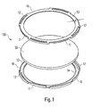
- the embodiment of the invention generally provided with the reference numeral 100 arrangement for holding a foil or disc-like element can in particular the exploded view of FIG. 1 be taken well.
- the arrangement 100 is used in the present case, the holder of a circular film 50, by the example, a color filter or the like to be realized.
- the arrangement 100 according to the invention it is also possible with the arrangement 100 according to the invention to hold elements which are not intended to influence the color of the light but, for example, to influence the light emission characteristic accordingly.
- elements which are not intended to influence the color of the light but, for example, to influence the light emission characteristic accordingly.
- light-scattering films or films with refractive structures, in particular prismatic structures or the like are also possible.
- the optical elements 50 to be held need not have a specific, fixed predetermined thickness but can be selected within a certain range, since the arrangement 100 here offers a certain latitude.
- the arrangement 100 is formed by two ring-like frame parts 10, which are joined together and then receive and hold the film 50 between them.
- An optical element according to the present invention is then formed by providing a film 50 or disk with the desired optical properties and placing it between the two frame parts 10. The structural unit formed thereby can then be used in a simple manner as an optical element, as will be explained in more detail below.
- connection of the two frame parts 10 is preferably carried out without tools.
- the frame parts 10 which are ideally made of plastic, have at their circumference alternately formed circular arc-segment-like projections 11 and recesses 12.
- the projections 11 engage in the corresponding opposite recesses 12 of the other frame part 10, wherein the interaction between projections 11 and recesses 12 is preferably such that a locking takes place.
- the projections 11 may have slightly inwardly facing angled portions, which then engage behind the recesses 12, so that ultimately both frame parts 10 can not be easily detached from each other.
- Both frame parts 10 have a circumferential annular region 13, which has a certain thickness d and serves to receive the outer peripheral region of the film 50.
- the film is thus clamped over its entire circumference between the two frame parts 10 and thus reliably held on all sides. This prevents that during use of the optical element, the film 50 curls or bulges due to unilateral load, which can lead to undesirable lighting properties.
- a slightly raised area or a protrusion 14 is preferably formed on the inner circumference of the annular area 13.
- the protrusion 14 is also provided in the upper part 10, so that there is a particularly efficient jamming of the film 50 between the two frame parts 10.
- the holding force of the assembled frame parts 10 is therefore sufficiently high to hold the film 50 reliably.
- Another special feature of the solution according to the invention further consists in that the frame parts 10 are formed identically. In fact, it is therefore a single type of frame part 10 which can be assembled with itself to the arrangement according to the invention. As FIG. 1 is removed, it is only necessary that one of the two frame parts 10 with respect to the other slightly rotated (here by 45 °) is aligned, since now a corresponding projection 11 is aligned with a corresponding recess 12 in the opposite frame part 10.
- the fact that only a single type of frame part has to be manufactured leads to a further optimization of the production costs, since in the case of production by injection molding, in particular, only a single tool must be available. Of course, it would also be conceivable to use two differently configured frame parts, which can be connected to one another in a corresponding manner.
- the solution according to the invention is not limited to the illustrated ring shape.
- the frame parts 10 could also be rectangular, in particular square, or also designed as polygons.
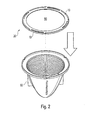
- an optical element 20 according to the present invention can be obtained in a simple manner by inserting a film 50 or disk between the two frame parts 10 and then latching them together. As in FIG. 2 is shown, then this optical element 20 can be arranged directly as a color filter or the like in the light exit region of a radiator or a downlight 60. Since the external dimensions of the optical element 20 are independent of the film 50 or disk used, accordingly, based on the solution according to the invention, a wide variety of optical elements can be formed in a simple and cost-effective manner, which can then be readily exchanged for one another.
Landscapes
- Physics & Mathematics (AREA)
- Engineering & Computer Science (AREA)
- General Engineering & Computer Science (AREA)
- General Physics & Mathematics (AREA)
- Optics & Photonics (AREA)
- Optical Filters (AREA)
Abstract
Description
- Die vorliegende Erfindung betrifft eine Anordnung zum Halten eines folien- oder scheibenartigen Elements für die Beeinflussung der Lichtabgabe einer Lichtquelle. Insbesondere soll mit Hilfe der erfindungsgemäßen Anordnung beispielsweise ein Filter für eine Leuchte geschaffen werden.
- Insbesondere bei Strahlern oder anderen Leuchten, die relativ stark gebündelt Licht abgeben, werden oftmals Filter also optische Elemente eingesetzt, um die Lichtabgabe der Leuchte in gewünschter Weise zu beeinflussen. Mit Hilfe derartiger Filter kann beispielsweise der Farbton des von dem Strahler abgegebenen Lichts modifiziert oder beispielsweise der oftmals unerwünschte Anteil an UV-Strahlung reduziert werden. Derartige Maßnahmen kommen beispielsweise häufig in Geschäften oder Museen zum Einsatz, um bestimmte Bereiche, Produkte oder Objekte durch eine entsprechende Beleuchtung besonders hervorzuheben oder ansprechender erscheinen zu lassen.
- Aus dem Stand der Technik sind verschiedene Möglichkeiten bekannt, derartige Filter zu realisieren. Üblicherweise handelt es sich um scheibenartige Elemente, welche also selbst eine gewisse Stabilität aufweisen und dann im Lichtaustrittsbereich des Strahlers angeordnet werden. Alternativ zu derartigen so genannten Filtergläsern könnten auch Folien verwendet werden, die dann allerdings durch zusätzliche Maßnahmen stabilisiert werden müssen, um sinnvoll zum Einsatz kommen zu können. Hierfür ist beispielsweise bekannt, die Filterfolie zwischen zwei üblicherweise glasklare Scheiben einzulegen und die hieraus resultierende sandwichartige Anordnung dann als Filter zu verwenden.
- Insgesamt gesehen stellen die aus dem Stand der Technik bekannten Lösungen verhältnismäßig komplexe oder großvolumige Anordnungen dar, welche auch verhältnismäßig teuer in ihrer Herstellung sind. Sollen nunmehr bei einem Strahler öfter dessen Lichtabstrahleigenschaften durch den Wechsel eines Filters verändert werden, was insbesondere in Museen oder Geschäften durchaus der Fall sein kann, so wäre es vorteilhaft, kostengünstiger herzustellende Filter verwenden zu können, welche darüber hinaus in einfacher Weise in unterschiedlichen Varianten, insbesondere mit unterschiedlichen optischen Eigenschaften realisiert werden können. Der vorliegenden Erfindung liegt deshalb die Aufgabenstellung zugrunde, eine neuartige Möglichkeit zum Realisieren eines Filters beispielsweise für einen Strahler zur Verfügung zu stellen.
- Die Aufgabe wird durch eine Anordnung zum Halten eines folien- oder scheibenartigen Elements zur Beeinflussung der Lichtabgabe einer Lichtquelle mit den Merkmalen des Anspruchs 1 gelöst.
- Die erfindungsgemäße Lösung beruht auf dem Gedanken, eine rahmenartige Halterung zur Verfügung zu stellen, welche in einfacher Weise zur Halterung eines optisch wirksamen Elements genutzt werden kann. Insbesondere soll die Halterung dazu geeignet sein, Folien zuverlässig derart aufzunehmen, dass sie als optischer Filter genutzt werden können. Hierzu ist vorgesehen, die Halterung durch zwei ringartige Rahmenteile zu bilden, welche miteinander zu dem Rahmen verbunden werden können und ferner im zusammengefügten Zustand das optisch wirksame Element, also die Folie oder eine dünne Scheibe klemmend halten.
- Gemäß der vorliegenden Erfindung wird dementsprechend eine Anordnung zum Halten eines folien- oder scheibenartigen Elements zur Beeinflussung der Lichtabgabe einer Lichtquelle vorgeschlagen, wobei die Anordnung durch zwei ringartige Rahmenteile gebildet ist, welche dazu ausgebildet sind, miteinander zu einem Rahmen verbunden zu werden und im zusammengefügten Zustand das folien- oder scheibenartige Element klemmend zu halten.
- Mit Hilfe der erfindungsgemäßen Halterung können also in einfacher Weise optische Elemente in unterschiedlichsten Varianten realisiert werden. Es ist lediglich erforderlich, eine entsprechend geeignete Folie bzw. ein scheibenartiges Element mit den gewünschten Eigenschaften zu wählen, welche dann von der erfindungsgemäßen Anordnung aufgenommen wird, so dass letztendlich dann beispielsweise ein Farbfilter oder dergleichen erhalten wird. Die Anordnung ist dabei derart, dass sowohl folienartige Elemente, also instabile Elemente, als auch scheibenartige Elemente, die selbst eine gewisse Dicke und damit Eigenstabilität aufweisen, aufgenommen werden können. Aufgrund dieser Flexibilität können also unterschiedliche Materialien mit unterschiedlichsten Eigenschaften genutzt werden, um letztendlich das optische Element zu bilden.
- Vorzugweise sind hierbei die beiden Rahmenteile derart ausgestaltet, dass sie das folien- oder scheibenartige Element im zusammengefügten Zustand über seinen gesamten Umfang hinweg halten. Insbesondere beim Einsatz von Folien ist dies von Vorteil, da hier also eine Stabilisierung des optisch wirksamen Elements über seinen gesamten Umfang hinweg erzielt wird und dementsprechend nicht die Gefahr besteht, dass während der Verwendung des optischen Elements sich die Folie beispielsweise wellt oder wölbt, was in ungewünschten lichttechnischen Effekten resultieren könnte.
- Die beiden Rahmenteile können hierzu an ihrem der Rahmenöffnung zugewandten Bereich jeweils einen dem anderen Rahmenteil zugewandten leicht vorstehenden Bereich z.B. in Form einer Rippe aufweisen. Hierdurch werden die folien- oder scheibenartigen Elemente mit hoher Klemmkraft gehalten, sodass in jedem Fall die gewünschte Stabilität erzielt des optischen Elements wird.
- Vorzugsweise sind die beiden Rahmenteile derart ausgestaltet, dass sie werkzeuglos miteinander verbunden werden können. Hierfür kann insbesondere vorgesehen sein, dass die beiden Rahmenteile miteinander verrastet werden.
- Gemäß einer besonders bevorzugten Ausführungsform der Erfindung ist ferner vorgesehen, dass die Rahmenteile identisch ausgebildet sind. Die Rahmenteile müssen also lediglich in einer einzigen Konfiguration bzw. Geometrie hergestellt werden und können dann jeweils zu Paaren miteinander verbunden werden, um die erfindungsgemäße Halterungsanordnung zu bilden. Auch diese Maßnahme wirkt sich nochmals positiv auf die Herstellungskosten aus. Vorzugsweise bestehen die beiden Rahmenteile aus Kunststoff und können dementsprechend im Spritzgussverfahren hergestellt werden. Dabei bestehen für die Form der Rahmenteile keine gravierenden Einschränkungen. Sie können beispielsweise kreisförmig oder quadratisch ausgebildet sein, wobei selbstverständlich auch andere Formen denkbar wären.
- Mit Hilfe der erfindungsgemäßen Halterung kann also dann in einfacher Weise ein optisches Element gebildet werden, wobei dessen optische Eigenschaften ausschließlich von den Eigenschaften des folien- oder scheibenartigen Elements abhängen. Hierbei kann es sich beispielsweise um ein Farbfilter halten. Denkbar wäre allerdings auch, Folien bzw. Scheiben zu verwenden, welche lichtstreuende oder lichtbrechende Strukturen, beispielsweise Prismenstrukturen aufweisen. Da die Außenabmessungen des optischen Elements ausschließlich von der erfindungsgemäßen Halterungsanordnung abhängen, können dann also in einfacher Weise optische Elemente mit unterschiedlichen Eigenschaften gegeneinander ausgetauscht werden und damit die Lichtabgabeeigenschaften einer Leuchte, insbesondere eines Strahlers modifiziert werden.
- Nachfolgend soll die Erfindung anhand der beiliegenden Zeichnung näher erläutert werden. Es zeigen:
- Figur 1
- ein optisches Element mit der erfindungsgemäßen Anordnung zur Halterung eines folien- oder scheibenartigen Elements in Explosionsdarstellung und
- Figur 2
- ein Beispiel der Verwendung eines erfindungsgemäßen optischen Elements.
- Die Ausgestaltung der erfindungsgemäßen, allgemein mit dem Bezugszeichen 100 versehenen Anordnung zur Halterung eines folien- oder scheibenartigen Elements kann insbesondere der Explosionsdarstellung von
Figur 1 gut entnommen werden. - Die Anordnung 100 dient im vorliegenden Fall der Halterung einer kreisrunden Folie 50, durch die beispielsweise ein Farbfilter oder dergleichen realisiert werden soll. Wie bereits erwähnt können mit der erfindungsgemäßen Anordnung 100 auch Elemente gehalten werden, die nicht einer Beeinflussung der Farbe des Lichts dienen sondern beispielsweise die Lichtabstrahlcharakteristik entsprechend beeinflussen sollen. Denkbar wären insbesondere auch lichtstreuende Folien oder Folien mit lichtbrechenden Strukturen, insbesondere Prismenstrukturen oder dergleichen. Dabei müssen die zu haltenden optischen Elemente 50 nicht eine bestimmte, fest vorgegebene Dicke aufweisen sondern können innerhalb eines gewissen Bereichs gewählt werden, da die Anordnung 100 hier einen gewissen Spielraum bietet.
- Erfindungsgemäß ist die Anordnung 100 durch zwei ringartige Rahmenteile 10 gebildet, welche zusammengefügt werden und zwischen sich dann die Folie 50 aufnehmen und halten. Ein optisches Element entsprechend der vorliegenden Erfindung wird dann also dadurch gebildet, dass eine Folie 50 bzw. Scheibe mit den gewünschten optischen Eigenschaften bereitgestellt und zwischen die beiden Rahmenteile 10 eingelegt wird. Die hierdurch gebildete Baueinheit kann dann in einfacher Weise als optisches Element verwendet werden, wie nachfolgend noch näher erläutert wird.
- Das Verbinden der beiden Rahmenteile 10 erfolgt vorzugsweise werkzeuglos. Im vorliegenden Fall ist hierzu vorgesehen, dass die idealerweise aus Kunststoff hergestellten Rahmenteile 10 an ihrem Umfang alternierend ausgebildete kreisbogenabschnittartige Vorsprünge 11 sowie Ausnehmungen 12 aufweisen. Beim Zusammenfügen beider Rahmenteile 10 greifen die Vorsprünge 11 in die entsprechend gegenüberliegenden Ausnehmungen 12 des anderen Rahmenteils 10 ein, wobei das Zusammenwirken zwischen Vorsprüngen 11 und Ausnehmungen 12 vorzugweise derart ist, dass ein Verrasten erfolgt. Hierzu können beispielsweise die Vorsprünge 11 leicht nach innen weisende abgewinkelte Abschnitte aufweisen, welche dann die Ausnehmungen 12 hintergreifen, so dass letztendlich beide Rahmenteile 10 nicht mehr ohne Weiteres voneinander gelöst werden können.
- Beide Rahmenteile 10 weisen einen umlaufenden Ringbereich 13 auf, der eine gewisse Dicke d aufweist und der Aufnahme des Außenumfangbereichs der Folie 50 dient. Die Folie wird also über ihren gesamten Umfang hinweg zwischen beide Rahmenteile 10 eingespannt und somit von allen Seiten her zuverlässig gehalten. Hierdurch wird verhindert, dass während der Verwendung des optischen Elements sich die Folie 50 aufgrund einseitiger Belastung wellt oder wölbt, was zu ungewünschten lichttechnischen Eigenschaften führen kann. Wie ferner insbesondere bei dem unteren Rahmenteil 10 in
Figur 1 erkennbar ist, ist dabei vorzugweise am Innenumfang des Ringbereichs 13 ein leicht erhabener Bereich bzw. eine Vorwölbung 14 ausgebildet. In gleicher Weise ist die Vorwölbung 14 auch bei dem oberen Teil 10 vorgesehen, sodass hier ein besonders effizientes Verklemmen der Folie 50 zwischen beiden Rahmenteilen 10 erfolgt. Die Haltekraft der zusammengefügten Rahmenteile 10 ist also ausreichend hoch, um die Folie 50 zuverlässig zu halten. - Eine weitere Besonderheit der erfindungsgemäßen Lösung besteht ferner darin, dass die Rahmenteile 10 identisch ausgebildet sind. Tatsächlich handelt es sich also um einen einzigen Typ eines Rahmenteils 10, der mit sich selbst zu der erfindungsgemäßen Anordnung zusammengefügt werden kann. Wie
Figur 1 entnehmbar ist, ist lediglich erforderlich, dass eines der beiden Rahmenteile 10 gegenüber dem anderen leicht verdreht (hier um 45°) ausgerichtet wird, da nunmehr dann ein entsprechender Vorsprung 11 auf eine entsprechende Ausnehmung 12 in dem gegenüberliegenden Rahmenteil 10 ausgerichtet ist. Die Tatsache, dass lediglich ein einziger Typ eines Rahmenteils hergestellt werden muss, führt zu einer weiteren Optimierung der Herstellungskosten, da insbesondere im Falle der Herstellung im Spritzgussverfahren lediglich ein einziges Werkzeug zur Verfügung stehen muss. Selbstverständlich wäre es allerdings auch denkbar, zwei unterschiedlich ausgestaltete Rahmenteile zu nutzen, die in entsprechender Weise miteinander verbunden werden können. - Anzumerken ist ferner, dass die erfindungsgemäße Lösung nicht auf die dargestellte Ringform beschränkt ist. In gleicher Weise könnten die Rahmenteile 10 auch rechteckig, insbesondere quadratisch, oder auch als Polygone ausgebildet sein. Auch in diesem Fall würde die Möglichkeit bestehen, die Vorsprünge 11 und Ausnehmungen 12 derart auszubilden, dass Rahmenteile eines identischen Typs mit sich selbst verrastet werden können, um die erfindungsgemäße Anordnung zu bilden.
- Letztendlich kann also ein optisches Element 20 gemäß der vorliegenden Erfindung in einfacher Weise dadurch erhalten werden, dass eine Folie 50 oder Scheibe zwischen beide Rahmenteile 10 eingelegt und diese dann miteinander verrastet werden. Wie in
Figur 2 dargestellt ist, kann dann dieses optische Element 20 unmittelbar als Farbfilter oder dergleichen im Lichtaustrittsbereich eines Strahlers oder eines Downlights 60 angeordnet werden. Da die Außenabmessungen des optischen Elements 20 von der verwendeten Folie 50 bzw. Scheibe unabhängig sind, können dementsprechend auf Basis der erfindungsgemäßen Lösung unterschiedlichste optische Elemente in einfacher und kostengünstiger Weise gebildet werden, die dann jeweils ohne Weiteres gegeneinander ausgetauscht werden können.
Claims (10)
- Anordnung (100) zum Halten eines folien- oder scheibenartigen Elements (50) zur Beeinflussung der Lichtabgabe einer Lichtquelle,
wobei die Anordnung (100) durch zwei ringartige Rahmenteile (10) gebildet ist, welche dazu ausgebildet sind, miteinander zu einem Rahmen verbunden zu werden und im zusammengefügten Zustand das folien- oder scheibenartige Element (50) klemmend zu halten. - Anordnung nach Anspruch 1,
dadurch gekennzeichnet,
dass die beiden Rahmenteile (10) das folien- oder scheibenartige Element (50) im zusammengefügten Zustand über seinen gesamten Umfang halten. - Anordnung nach Anspruch 1 oder 2,
dadurch gekennzeichnet,
dass die beiden Rahmenteile (10) an ihrem der Rahmenöffnung zugewandten Bereich jeweils einen dem anderen Rahmenteil (10) zugewandten Vorsprung bzw. eine Vorwölbung (14) aufweisen. - Anordnung nach einem der vorherigen Ansprüche,
dadurch gekennzeichnet,
dass die beiden Rahmenteile (10) werkzeuglos miteinander verbindbar, insbesondere verrastbar sind. - Anordnung nach einem der vorherigen Ansprüche,
dadurch gekennzeichnet,
dass die beiden Rahmenteile (10) identisch ausgebildet sind. - Anordnung nach einem der vorherigen Ansprüche.
dadurch gekennzeichnet,
dass die beiden Rahmenteile (10) aus Kunststoff bestehen. - Anordnung nach einem der vorherigen Ansprüche,
dadurch gekennzeichnet,
dass die beiden Rahmenteile (10) im Wesentlichen kreisförmig oder quadratisch ausgebildet sind. - Optische Element (20) zur Beeinflussung der Lichtabgabe einer Lichtquelle, aufweisend ein folien- oder scheibenartiges Element (50) mit optischen Eigenschaften sowie einer Anordnung (100) zur Halterung des folien- oder scheibenartiges Elements (50) gemäß einem der vorherigen Ansprüche.
- Optisches Element nach Anspruch 8,
dadurch gekennzeichnet,
dass es sich bei dem folien- oder scheibenartiges Element (50) um ein Farbfilter handelt. - Optisches Element nach Anspruch 8,
dadurch gekennzeichnet,
dass es sich bei dem folien- oder scheibenartiges Element (50) um ein Element mit lichtbrechenden Strukturen, insbesondere mit Prismenstrukturen handelt.
Applications Claiming Priority (1)
| Application Number | Priority Date | Filing Date | Title |
|---|---|---|---|
| DE201320009268 DE202013009268U1 (de) | 2013-10-18 | 2013-10-18 | Anordnung zum Halten eines Elements zur Beeinflussung der Lichtabgabe einer Lichtquelle |
Publications (2)
| Publication Number | Publication Date |
|---|---|
| EP2869102A1 true EP2869102A1 (de) | 2015-05-06 |
| EP2869102B1 EP2869102B1 (de) | 2019-06-19 |
Family
ID=51870799
Family Applications (1)
| Application Number | Title | Priority Date | Filing Date |
|---|---|---|---|
| EP14188966.7A Not-in-force EP2869102B1 (de) | 2013-10-18 | 2014-10-15 | Anordnung zum Halten eines Elements zur Beeinflussung der Lichtabgabe einer Lichtquelle |
Country Status (2)
| Country | Link |
|---|---|
| EP (1) | EP2869102B1 (de) |
| DE (1) | DE202013009268U1 (de) |
Cited By (1)
| Publication number | Priority date | Publication date | Assignee | Title |
|---|---|---|---|---|
| WO2025256178A1 (zh) * | 2024-06-13 | 2025-12-18 | 华为技术有限公司 | 镜头组件、摄像头模组和电子设备 |
Citations (7)
| Publication number | Priority date | Publication date | Assignee | Title |
|---|---|---|---|---|
| DE525609C (de) * | 1929-10-12 | 1931-05-27 | Carl Neithold A G | Vorrichtung zum Festklemmen von Farbfiltern, Vorsatzlinsen o. dgl. an Objektivfassungen |
| US4502760A (en) * | 1982-03-29 | 1985-03-05 | Jules Alfille | Accessory holder module for optical equipment |
| DE29601081U1 (de) * | 1996-01-23 | 1996-03-28 | Fa. Huss Lichttechnik, 89129 Langenau | Farbfilterhalter |
| DE29705097U1 (de) * | 1997-03-05 | 1997-12-11 | Schättgen, Horst, 51069 Köln | Farbfiltervorsatz mit Farbfilterwechseleinrichtung |
| DE19917137C1 (de) * | 1999-04-15 | 2000-12-14 | Wila Leuchten Ag Sevelen | Leuchte mit einer Lichtverteilungsscheibe |
| EP1331437A1 (de) * | 2002-01-23 | 2003-07-30 | Zumtobel Staff GmbH & Co. KG | Lichtstrahler mit Reflektor |
| EP2648029A2 (de) * | 2012-04-05 | 2013-10-09 | Mitutoyo Corporation | Adapter zur Korrektur für Glasdicke, Feldlinse und Verfahren zur Montage eines Adapters auf einer Feldlinse |
Family Cites Families (8)
| Publication number | Priority date | Publication date | Assignee | Title |
|---|---|---|---|---|
| DE1778807U (de) * | 1958-09-15 | 1958-12-04 | Agfa Ag | Raehmchen fuer diapositivfilm. |
| US2959882A (en) * | 1959-05-26 | 1960-11-15 | Filmosto Projektion | Frame structures for receiving transparencies |
| DE1984326U (de) * | 1968-02-10 | 1968-04-25 | Manfred Schaefer | Rahmen fuer filmdiapositive. |
| SE7611101L (sv) * | 1975-10-09 | 1977-04-10 | Bellmann & Co | Diaram |
| DE19520502A1 (de) * | 1995-06-03 | 1996-12-05 | Luenig Helmar | Vorrichtung zur Beleuchtung von zu fotografierenden Gegenständen |
| DE20207639U1 (de) * | 2002-05-14 | 2003-09-25 | Sonlux Licht- und Elektroinstallation GmbH & Co KG, 99706 Sondershausen | Optisches Element zur Beeinflussung der mit einer Leuchte bewirkten Beleuchtung sowie Leuchte und Gußform zur Herstellung eines optischen Elementes |
| DE102007038899B4 (de) * | 2007-08-13 | 2021-10-07 | Arnold & Richter Cine Technik Gmbh & Co. Betriebs Kg | Verfahren und Vorrichtung zur Steuerung des Kontrastumfangs des auf ein Bildaufnahmemedium fallenden Bildaufnahmelichts |
| JP5532704B2 (ja) * | 2009-07-01 | 2014-06-25 | 株式会社ニコン | 撮影用照明装置 |
-
2013
- 2013-10-18 DE DE201320009268 patent/DE202013009268U1/de not_active Expired - Lifetime
-
2014
- 2014-10-15 EP EP14188966.7A patent/EP2869102B1/de not_active Not-in-force
Patent Citations (7)
| Publication number | Priority date | Publication date | Assignee | Title |
|---|---|---|---|---|
| DE525609C (de) * | 1929-10-12 | 1931-05-27 | Carl Neithold A G | Vorrichtung zum Festklemmen von Farbfiltern, Vorsatzlinsen o. dgl. an Objektivfassungen |
| US4502760A (en) * | 1982-03-29 | 1985-03-05 | Jules Alfille | Accessory holder module for optical equipment |
| DE29601081U1 (de) * | 1996-01-23 | 1996-03-28 | Fa. Huss Lichttechnik, 89129 Langenau | Farbfilterhalter |
| DE29705097U1 (de) * | 1997-03-05 | 1997-12-11 | Schättgen, Horst, 51069 Köln | Farbfiltervorsatz mit Farbfilterwechseleinrichtung |
| DE19917137C1 (de) * | 1999-04-15 | 2000-12-14 | Wila Leuchten Ag Sevelen | Leuchte mit einer Lichtverteilungsscheibe |
| EP1331437A1 (de) * | 2002-01-23 | 2003-07-30 | Zumtobel Staff GmbH & Co. KG | Lichtstrahler mit Reflektor |
| EP2648029A2 (de) * | 2012-04-05 | 2013-10-09 | Mitutoyo Corporation | Adapter zur Korrektur für Glasdicke, Feldlinse und Verfahren zur Montage eines Adapters auf einer Feldlinse |
Cited By (1)
| Publication number | Priority date | Publication date | Assignee | Title |
|---|---|---|---|---|
| WO2025256178A1 (zh) * | 2024-06-13 | 2025-12-18 | 华为技术有限公司 | 镜头组件、摄像头模组和电子设备 |
Also Published As
| Publication number | Publication date |
|---|---|
| EP2869102B1 (de) | 2019-06-19 |
| DE202013009268U1 (de) | 2015-02-13 |
Similar Documents
| Publication | Publication Date | Title |
|---|---|---|
| EP3105499B2 (de) | Längliche mehrteilige linsenanordnung sowie leuchte mit einer solchen linsenanordnung | |
| EP2924333A1 (de) | Modulare Leuchte | |
| EP2639108A2 (de) | Beleuchtungseinrichtung, insbesondere Konturbeleuchtung für ein Kraftfahrzeug | |
| DE202010011734U1 (de) | Taschenlampe | |
| EP2796770B1 (de) | Leuchte mit einer Lichterzeugungseinheit und einem Rahmenelement | |
| EP2796780A1 (de) | Leuchte mit einstellbarer Lichtabstrahlcharakteristik | |
| EP2869102B1 (de) | Anordnung zum Halten eines Elements zur Beeinflussung der Lichtabgabe einer Lichtquelle | |
| DE102010041473A1 (de) | Leuchtmodulanordnung mit einer LED auf einer Platine | |
| DE202017102009U1 (de) | Leuchte | |
| EP3686480B1 (de) | Anordnung zur lichtabgabe mit veränderbarer lichtabstrahlcharakteristik | |
| DE202011051295U1 (de) | Lichtgitter | |
| EP1389711B1 (de) | Einbauleuchte | |
| EP2800929B1 (de) | Leuchtenelement und leuchte | |
| DE102014205819B4 (de) | System zur Aufnahme von Lichtmodulen sowie Verfahren für dessen Herstellung | |
| EP3139085A1 (de) | Strahler mit verschiebbarem optischem element | |
| EP3156716B1 (de) | Längliche leuchte | |
| DE102020004755A1 (de) | Haltesystem und Verwendung des Haltesystems | |
| EP2873910A1 (de) | Leuchtenoptik und Lichtbandleuchte | |
| DE202015106600U1 (de) | Leuchte | |
| DE102012018517A1 (de) | Beleuchtungseinrichtung für ein Fahrzeug | |
| EP2578930B1 (de) | Lichtmodul für eine Außenleuchte | |
| AT14644U1 (de) | Beleuchtungsanordnung mit zumindest zwei optischen Elementen | |
| DE202018101591U1 (de) | Leuchte | |
| WO2023067009A1 (de) | Beleuchtungskörper | |
| EP3064827B1 (de) | Anordnung zur montage eines led-moduls auf einer oberfläche eines kühlkörpers sowie led-anordnung |
Legal Events
| Date | Code | Title | Description |
|---|---|---|---|
| PUAI | Public reference made under article 153(3) epc to a published international application that has entered the european phase |
Free format text: ORIGINAL CODE: 0009012 |
|
| 17P | Request for examination filed |
Effective date: 20141015 |
|
| AK | Designated contracting states |
Kind code of ref document: A1 Designated state(s): AL AT BE BG CH CY CZ DE DK EE ES FI FR GB GR HR HU IE IS IT LI LT LU LV MC MK MT NL NO PL PT RO RS SE SI SK SM TR |
|
| AX | Request for extension of the european patent |
Extension state: BA ME |
|
| R17P | Request for examination filed (corrected) |
Effective date: 20151012 |
|
| RBV | Designated contracting states (corrected) |
Designated state(s): AL AT BE BG CH CY CZ DE DK EE ES FI FR GB GR HR HU IE IS IT LI LT LU LV MC MK MT NL NO PL PT RO RS SE SI SK SM TR |
|
| STAA | Information on the status of an ep patent application or granted ep patent |
Free format text: STATUS: EXAMINATION IS IN PROGRESS |
|
| 17Q | First examination report despatched |
Effective date: 20181001 |
|
| GRAP | Despatch of communication of intention to grant a patent |
Free format text: ORIGINAL CODE: EPIDOSNIGR1 |
|
| STAA | Information on the status of an ep patent application or granted ep patent |
Free format text: STATUS: GRANT OF PATENT IS INTENDED |
|
| INTG | Intention to grant announced |
Effective date: 20190220 |
|
| GRAS | Grant fee paid |
Free format text: ORIGINAL CODE: EPIDOSNIGR3 |
|
| GRAA | (expected) grant |
Free format text: ORIGINAL CODE: 0009210 |
|
| STAA | Information on the status of an ep patent application or granted ep patent |
Free format text: STATUS: THE PATENT HAS BEEN GRANTED |
|
| AK | Designated contracting states |
Kind code of ref document: B1 Designated state(s): AL AT BE BG CH CY CZ DE DK EE ES FI FR GB GR HR HU IE IS IT LI LT LU LV MC MK MT NL NO PL PT RO RS SE SI SK SM TR |
|
| REG | Reference to a national code |
Ref country code: GB Ref legal event code: FG4D Free format text: NOT ENGLISH |
|
| REG | Reference to a national code |
Ref country code: CH Ref legal event code: EP Ref country code: CH Ref legal event code: NV Representative=s name: VALIPAT S.A. C/O BOVARD SA NEUCHATEL, CH |
|
| REG | Reference to a national code |
Ref country code: IE Ref legal event code: FG4D Free format text: LANGUAGE OF EP DOCUMENT: GERMAN |
|
| REG | Reference to a national code |
Ref country code: AT Ref legal event code: REF Ref document number: 1146240 Country of ref document: AT Kind code of ref document: T Effective date: 20190715 |
|
| REG | Reference to a national code |
Ref country code: DE Ref legal event code: R096 Ref document number: 502014011979 Country of ref document: DE |
|
| REG | Reference to a national code |
Ref country code: NL Ref legal event code: MP Effective date: 20190619 |
|
| PG25 | Lapsed in a contracting state [announced via postgrant information from national office to epo] |
Ref country code: SE Free format text: LAPSE BECAUSE OF FAILURE TO SUBMIT A TRANSLATION OF THE DESCRIPTION OR TO PAY THE FEE WITHIN THE PRESCRIBED TIME-LIMIT Effective date: 20190619 Ref country code: HR Free format text: LAPSE BECAUSE OF FAILURE TO SUBMIT A TRANSLATION OF THE DESCRIPTION OR TO PAY THE FEE WITHIN THE PRESCRIBED TIME-LIMIT Effective date: 20190619 Ref country code: AL Free format text: LAPSE BECAUSE OF FAILURE TO SUBMIT A TRANSLATION OF THE DESCRIPTION OR TO PAY THE FEE WITHIN THE PRESCRIBED TIME-LIMIT Effective date: 20190619 Ref country code: FI Free format text: LAPSE BECAUSE OF FAILURE TO SUBMIT A TRANSLATION OF THE DESCRIPTION OR TO PAY THE FEE WITHIN THE PRESCRIBED TIME-LIMIT Effective date: 20190619 Ref country code: NO Free format text: LAPSE BECAUSE OF FAILURE TO SUBMIT A TRANSLATION OF THE DESCRIPTION OR TO PAY THE FEE WITHIN THE PRESCRIBED TIME-LIMIT Effective date: 20190919 Ref country code: LT Free format text: LAPSE BECAUSE OF FAILURE TO SUBMIT A TRANSLATION OF THE DESCRIPTION OR TO PAY THE FEE WITHIN THE PRESCRIBED TIME-LIMIT Effective date: 20190619 |
|
| REG | Reference to a national code |
Ref country code: LT Ref legal event code: MG4D |
|
| PG25 | Lapsed in a contracting state [announced via postgrant information from national office to epo] |
Ref country code: RS Free format text: LAPSE BECAUSE OF FAILURE TO SUBMIT A TRANSLATION OF THE DESCRIPTION OR TO PAY THE FEE WITHIN THE PRESCRIBED TIME-LIMIT Effective date: 20190619 Ref country code: BG Free format text: LAPSE BECAUSE OF FAILURE TO SUBMIT A TRANSLATION OF THE DESCRIPTION OR TO PAY THE FEE WITHIN THE PRESCRIBED TIME-LIMIT Effective date: 20190919 Ref country code: GR Free format text: LAPSE BECAUSE OF FAILURE TO SUBMIT A TRANSLATION OF THE DESCRIPTION OR TO PAY THE FEE WITHIN THE PRESCRIBED TIME-LIMIT Effective date: 20190920 Ref country code: LV Free format text: LAPSE BECAUSE OF FAILURE TO SUBMIT A TRANSLATION OF THE DESCRIPTION OR TO PAY THE FEE WITHIN THE PRESCRIBED TIME-LIMIT Effective date: 20190619 |
|
| PG25 | Lapsed in a contracting state [announced via postgrant information from national office to epo] |
Ref country code: NL Free format text: LAPSE BECAUSE OF FAILURE TO SUBMIT A TRANSLATION OF THE DESCRIPTION OR TO PAY THE FEE WITHIN THE PRESCRIBED TIME-LIMIT Effective date: 20190619 Ref country code: EE Free format text: LAPSE BECAUSE OF FAILURE TO SUBMIT A TRANSLATION OF THE DESCRIPTION OR TO PAY THE FEE WITHIN THE PRESCRIBED TIME-LIMIT Effective date: 20190619 Ref country code: PT Free format text: LAPSE BECAUSE OF FAILURE TO SUBMIT A TRANSLATION OF THE DESCRIPTION OR TO PAY THE FEE WITHIN THE PRESCRIBED TIME-LIMIT Effective date: 20191021 Ref country code: SK Free format text: LAPSE BECAUSE OF FAILURE TO SUBMIT A TRANSLATION OF THE DESCRIPTION OR TO PAY THE FEE WITHIN THE PRESCRIBED TIME-LIMIT Effective date: 20190619 Ref country code: CZ Free format text: LAPSE BECAUSE OF FAILURE TO SUBMIT A TRANSLATION OF THE DESCRIPTION OR TO PAY THE FEE WITHIN THE PRESCRIBED TIME-LIMIT Effective date: 20190619 Ref country code: RO Free format text: LAPSE BECAUSE OF FAILURE TO SUBMIT A TRANSLATION OF THE DESCRIPTION OR TO PAY THE FEE WITHIN THE PRESCRIBED TIME-LIMIT Effective date: 20190619 |
|
| PG25 | Lapsed in a contracting state [announced via postgrant information from national office to epo] |
Ref country code: IS Free format text: LAPSE BECAUSE OF FAILURE TO SUBMIT A TRANSLATION OF THE DESCRIPTION OR TO PAY THE FEE WITHIN THE PRESCRIBED TIME-LIMIT Effective date: 20191019 Ref country code: SM Free format text: LAPSE BECAUSE OF FAILURE TO SUBMIT A TRANSLATION OF THE DESCRIPTION OR TO PAY THE FEE WITHIN THE PRESCRIBED TIME-LIMIT Effective date: 20190619 Ref country code: IT Free format text: LAPSE BECAUSE OF FAILURE TO SUBMIT A TRANSLATION OF THE DESCRIPTION OR TO PAY THE FEE WITHIN THE PRESCRIBED TIME-LIMIT Effective date: 20190619 Ref country code: ES Free format text: LAPSE BECAUSE OF FAILURE TO SUBMIT A TRANSLATION OF THE DESCRIPTION OR TO PAY THE FEE WITHIN THE PRESCRIBED TIME-LIMIT Effective date: 20190619 |
|
| PG25 | Lapsed in a contracting state [announced via postgrant information from national office to epo] |
Ref country code: TR Free format text: LAPSE BECAUSE OF FAILURE TO SUBMIT A TRANSLATION OF THE DESCRIPTION OR TO PAY THE FEE WITHIN THE PRESCRIBED TIME-LIMIT Effective date: 20190619 |
|
| PG25 | Lapsed in a contracting state [announced via postgrant information from national office to epo] |
Ref country code: DK Free format text: LAPSE BECAUSE OF FAILURE TO SUBMIT A TRANSLATION OF THE DESCRIPTION OR TO PAY THE FEE WITHIN THE PRESCRIBED TIME-LIMIT Effective date: 20190619 Ref country code: PL Free format text: LAPSE BECAUSE OF FAILURE TO SUBMIT A TRANSLATION OF THE DESCRIPTION OR TO PAY THE FEE WITHIN THE PRESCRIBED TIME-LIMIT Effective date: 20190619 |
|
| PG25 | Lapsed in a contracting state [announced via postgrant information from national office to epo] |
Ref country code: IS Free format text: LAPSE BECAUSE OF FAILURE TO SUBMIT A TRANSLATION OF THE DESCRIPTION OR TO PAY THE FEE WITHIN THE PRESCRIBED TIME-LIMIT Effective date: 20200224 Ref country code: MC Free format text: LAPSE BECAUSE OF FAILURE TO SUBMIT A TRANSLATION OF THE DESCRIPTION OR TO PAY THE FEE WITHIN THE PRESCRIBED TIME-LIMIT Effective date: 20190619 |
|
| REG | Reference to a national code |
Ref country code: DE Ref legal event code: R097 Ref document number: 502014011979 Country of ref document: DE |
|
| PLBE | No opposition filed within time limit |
Free format text: ORIGINAL CODE: 0009261 |
|
| STAA | Information on the status of an ep patent application or granted ep patent |
Free format text: STATUS: NO OPPOSITION FILED WITHIN TIME LIMIT |
|
| PG2D | Information on lapse in contracting state deleted |
Ref country code: IS |
|
| PG25 | Lapsed in a contracting state [announced via postgrant information from national office to epo] |
Ref country code: LU Free format text: LAPSE BECAUSE OF NON-PAYMENT OF DUE FEES Effective date: 20191015 |
|
| 26N | No opposition filed |
Effective date: 20200603 |
|
| REG | Reference to a national code |
Ref country code: BE Ref legal event code: MM Effective date: 20191031 |
|
| PG25 | Lapsed in a contracting state [announced via postgrant information from national office to epo] |
Ref country code: SI Free format text: LAPSE BECAUSE OF FAILURE TO SUBMIT A TRANSLATION OF THE DESCRIPTION OR TO PAY THE FEE WITHIN THE PRESCRIBED TIME-LIMIT Effective date: 20190619 Ref country code: BE Free format text: LAPSE BECAUSE OF NON-PAYMENT OF DUE FEES Effective date: 20191031 |
|
| REG | Reference to a national code |
Ref country code: DE Ref legal event code: R084 Ref document number: 502014011979 Country of ref document: DE |
|
| PG25 | Lapsed in a contracting state [announced via postgrant information from national office to epo] |
Ref country code: IE Free format text: LAPSE BECAUSE OF NON-PAYMENT OF DUE FEES Effective date: 20191015 |
|
| PGFP | Annual fee paid to national office [announced via postgrant information from national office to epo] |
Ref country code: CH Payment date: 20201023 Year of fee payment: 7 Ref country code: AT Payment date: 20201021 Year of fee payment: 7 |
|
| PG25 | Lapsed in a contracting state [announced via postgrant information from national office to epo] |
Ref country code: CY Free format text: LAPSE BECAUSE OF FAILURE TO SUBMIT A TRANSLATION OF THE DESCRIPTION OR TO PAY THE FEE WITHIN THE PRESCRIBED TIME-LIMIT Effective date: 20190619 |
|
| PG25 | Lapsed in a contracting state [announced via postgrant information from national office to epo] |
Ref country code: HU Free format text: LAPSE BECAUSE OF FAILURE TO SUBMIT A TRANSLATION OF THE DESCRIPTION OR TO PAY THE FEE WITHIN THE PRESCRIBED TIME-LIMIT; INVALID AB INITIO Effective date: 20141015 Ref country code: MT Free format text: LAPSE BECAUSE OF FAILURE TO SUBMIT A TRANSLATION OF THE DESCRIPTION OR TO PAY THE FEE WITHIN THE PRESCRIBED TIME-LIMIT Effective date: 20190619 |
|
| REG | Reference to a national code |
Ref country code: CH Ref legal event code: PL |
|
| REG | Reference to a national code |
Ref country code: AT Ref legal event code: MM01 Ref document number: 1146240 Country of ref document: AT Kind code of ref document: T Effective date: 20211015 |
|
| PG25 | Lapsed in a contracting state [announced via postgrant information from national office to epo] |
Ref country code: MK Free format text: LAPSE BECAUSE OF FAILURE TO SUBMIT A TRANSLATION OF THE DESCRIPTION OR TO PAY THE FEE WITHIN THE PRESCRIBED TIME-LIMIT Effective date: 20190619 |
|
| PG25 | Lapsed in a contracting state [announced via postgrant information from national office to epo] |
Ref country code: LI Free format text: LAPSE BECAUSE OF NON-PAYMENT OF DUE FEES Effective date: 20211031 Ref country code: CH Free format text: LAPSE BECAUSE OF NON-PAYMENT OF DUE FEES Effective date: 20211031 Ref country code: AT Free format text: LAPSE BECAUSE OF NON-PAYMENT OF DUE FEES Effective date: 20211015 |
|
| PGFP | Annual fee paid to national office [announced via postgrant information from national office to epo] |
Ref country code: FR Payment date: 20221024 Year of fee payment: 9 |
|
| PGFP | Annual fee paid to national office [announced via postgrant information from national office to epo] |
Ref country code: GB Payment date: 20221018 Year of fee payment: 9 |
|
| P01 | Opt-out of the competence of the unified patent court (upc) registered |
Effective date: 20230530 |
|
| PGFP | Annual fee paid to national office [announced via postgrant information from national office to epo] |
Ref country code: DE Payment date: 20231027 Year of fee payment: 10 |
|
| GBPC | Gb: european patent ceased through non-payment of renewal fee |
Effective date: 20231015 |
|
| PG25 | Lapsed in a contracting state [announced via postgrant information from national office to epo] |
Ref country code: GB Free format text: LAPSE BECAUSE OF NON-PAYMENT OF DUE FEES Effective date: 20231015 |
|
| PG25 | Lapsed in a contracting state [announced via postgrant information from national office to epo] |
Ref country code: GB Free format text: LAPSE BECAUSE OF NON-PAYMENT OF DUE FEES Effective date: 20231015 Ref country code: FR Free format text: LAPSE BECAUSE OF NON-PAYMENT OF DUE FEES Effective date: 20231031 |
|
| REG | Reference to a national code |
Ref country code: DE Ref legal event code: R119 Ref document number: 502014011979 Country of ref document: DE |
|
| PG25 | Lapsed in a contracting state [announced via postgrant information from national office to epo] |
Ref country code: DE Free format text: LAPSE BECAUSE OF NON-PAYMENT OF DUE FEES Effective date: 20250501 |