EP2868923A2 - Actionnement de rigidité négative variable - Google Patents
Actionnement de rigidité négative variable Download PDFInfo
- Publication number
- EP2868923A2 EP2868923A2 EP14191185.9A EP14191185A EP2868923A2 EP 2868923 A2 EP2868923 A2 EP 2868923A2 EP 14191185 A EP14191185 A EP 14191185A EP 2868923 A2 EP2868923 A2 EP 2868923A2
- Authority
- EP
- European Patent Office
- Prior art keywords
- stiffness
- actuator
- load
- buckling
- end effector
- Prior art date
- Legal status (The legal status is an assumption and is not a legal conclusion. Google has not performed a legal analysis and makes no representation as to the accuracy of the status listed.)
- Granted
Links
- 238000000034 method Methods 0.000 claims abstract description 46
- 239000012636 effector Substances 0.000 claims description 84
- 238000011068 loading method Methods 0.000 claims description 57
- 238000005452 bending Methods 0.000 claims description 20
- 230000008859 change Effects 0.000 description 8
- 230000003247 decreasing effect Effects 0.000 description 5
- 230000006835 compression Effects 0.000 description 4
- 238000007906 compression Methods 0.000 description 4
- 230000007423 decrease Effects 0.000 description 4
- 238000006073 displacement reaction Methods 0.000 description 4
- 230000003993 interaction Effects 0.000 description 3
- 230000001747 exhibiting effect Effects 0.000 description 2
- 230000001939 inductive effect Effects 0.000 description 2
- 239000000463 material Substances 0.000 description 2
- 239000011159 matrix material Substances 0.000 description 2
- 230000007246 mechanism Effects 0.000 description 2
- 238000013459 approach Methods 0.000 description 1
- 230000004323 axial length Effects 0.000 description 1
- 230000008901 benefit Effects 0.000 description 1
- 238000005516 engineering process Methods 0.000 description 1
- 238000012986 modification Methods 0.000 description 1
- 230000004048 modification Effects 0.000 description 1
- 230000003287 optical effect Effects 0.000 description 1
- 230000001151 other effect Effects 0.000 description 1
Images


Classifications
-
- F—MECHANICAL ENGINEERING; LIGHTING; HEATING; WEAPONS; BLASTING
- F16—ENGINEERING ELEMENTS AND UNITS; GENERAL MEASURES FOR PRODUCING AND MAINTAINING EFFECTIVE FUNCTIONING OF MACHINES OR INSTALLATIONS; THERMAL INSULATION IN GENERAL
- F16F—SPRINGS; SHOCK-ABSORBERS; MEANS FOR DAMPING VIBRATION
- F16F7/00—Vibration-dampers; Shock-absorbers
-
- B—PERFORMING OPERATIONS; TRANSPORTING
- B25—HAND TOOLS; PORTABLE POWER-DRIVEN TOOLS; MANIPULATORS
- B25J—MANIPULATORS; CHAMBERS PROVIDED WITH MANIPULATION DEVICES
- B25J19/00—Accessories fitted to manipulators, e.g. for monitoring, for viewing; Safety devices combined with or specially adapted for use in connection with manipulators
- B25J19/06—Safety devices
- B25J19/068—Actuating means with variable stiffness
-
- B—PERFORMING OPERATIONS; TRANSPORTING
- B25—HAND TOOLS; PORTABLE POWER-DRIVEN TOOLS; MANIPULATORS
- B25J—MANIPULATORS; CHAMBERS PROVIDED WITH MANIPULATION DEVICES
- B25J19/00—Accessories fitted to manipulators, e.g. for monitoring, for viewing; Safety devices combined with or specially adapted for use in connection with manipulators
- B25J19/0091—Shock absorbers
Definitions
- the disclosure relates generally to actuation apparatus and methods and, more particularly, to variable negative stiffness actuation apparatus and methods.
- Actuators are known to convert energy into motion. By varying a stiffness of an actuator, one can better control the motion of the actuator. Methods and apparatus for varying a stiffness of an actuator are desirable.
- a method of varying an effective stiffness of an actuator includes providing an actuator. The method further includes varying an effective stiffness of the actuator based at least in part on non-linear deflection characteristics of buckling.
- varying the effective stiffness includes applying a load to a member.
- the load causes the member to buckle and the buckling of the member defines at least in part the non-linear deflection characteristics of buckling.
- the load is a compressive load.
- the load is a tensile load.
- the load is a bending load.
- the load is a torsional load.
- the method further includes varying a stiffness of the member.
- the stiffness of the member is based at least in part on the non-linear deflection characteristics of buckling. Varying the stiffness of the member varies the effective stiffness of the actuator.
- the method further includes varying the effective stiffness of the actuator not based at least in part on non-linear deflection characteristics of buckling.
- the method further includes controlling a position of an end effector of the actuator based at least in part on a force applied to the end effector.
- the force applied to the end effector causes a deflection of the end effector.
- the method further includes estimating the force applied to the end effector based at least in part on the deflection of the end effector and the effective stiffness of the actuator.
- the method further includes controlling the position of the end effector based at least in part on the estimated force.
- the first aspect may be provided alone or in combination with one or any combination of the examples of the first aspect discussed above.
- a method of varying an effective stiffness of an actuator includes applying a load to a member.
- the load causes the member to buckle, and the buckling produces non-linear deflection of the member.
- the method further includes varying an effective stiffness of an actuator based at least in part on the non-linear deflection of the member.
- a stiffness of the member is based at least in part on the non-linear deflection of the member.
- the method further includes varying the stiffness of the member. Varying the stiffness of the member varies the effective stiffness of the actuator.
- the method further includes varying the effective stiffness of the actuator not based at least in part on the non-linear deflection of the member.
- the second aspect may be provided alone or in combination with one or any combination of the examples of the second aspect discussed above.
- an actuator in a third aspect of the disclosure, includes an effective stiffness.
- the effective stiffness is based at least in part on non-linear deflection characteristics of buckling.
- the actuator further includes a member defining at least in part the effective stiffness of the actuator.
- the actuator further includes a loading module configured to apply a load to the member.
- the load causes the member to buckle, and the buckling produces non-linear deflection of the member.
- the effective stiffness of the actuator is based at least in part on the non-linear deflection of the member.
- a stiffness of the member is based at least in part on the non-linear deflection of the member.
- the actuator further includes a controller configured to vary the stiffness of the member. Varying the stiffness of the member varies the effective stiffness of the actuator.
- the loading module is configured to apply at least one of a compressive load, a tensile load, a bending load, and a torsional load to the member.
- the actuator further includes an end effector connected to the member.
- the actuator further includes a positioning module configured to control a position of the end effector.
- the positioning module is configured to control the position of the end effector based at least in part on a force applied to the end effector.
- the force applied to the end effector causes a deflection of the end effector.
- the controller is configured to estimate the force applied to the end effector based at least in part on the deflection of the end effector and the effective stiffness of the actuator.
- the positioning module is configured to control the position of the end effector based at least in part on the estimated force.
- the third aspect may be provided alone or in combination with one or any combination of the examples of the third aspect discussed above.
- Actuators can be used in a variety of applications to convert energy to motion, including but not limited to applications involving robotics, human-machine interaction, exoskeletons, prosthetic devices, rehabilitation and service robots as well as other areas of technology where a control system acts upon an environment.
- an actuator can include an end effector that interacts with the environment in various ways depending on the particular application.
- the present disclosure is to be understood to include all types of actuators, including any device configured to convert energy to motion such as hydraulic, pneumatic, electric, and mechanical actuators, as well as other actuators not explicitly described herein.
- An actuator has a stiffness (e.g. an effective stiffness) which, in some examples, can be defined at least in part by the stiffness (e.g.
- a variable stiffness actuator has a stiffness (e.g. an effective stiffness) that can be varied (e.g. controlled, modulated) to include a range of stiffnesses.
- the present disclosure describes apparatus and methods for varying a stiffness of an actuator.
- the present disclosure describes apparatus and methods for varying a stiffness of an actuator based at least in part on non-linear deflection characteristics of buckling (e.g. variable negative stiffness).
- the apparatus and methods described herein can vary a stiffness of an actuator to include at least one of a positive stiffness, a zero stiffness, and a negative stiffness.
- One method includes providing an actuator.
- the actuator can be any actuator having a stiffness (e.g. an effective stiffness), including but not limited to the various example actuators described herein.
- the method can further include varying the effective stiffness of the actuator based at least on part on non-linear deflection characteristics of buckling (e.g. negative stiffness).
- Non-linear deflection characteristics of buckling can include any result, attribute, behavior, or other effect brought about by buckling, including any change with respect to force-displacement characteristics of a member.
- varying the stiffness can include applying a load to a member.
- the member can include a beam, a shaft, a column, a rod, a spring, a plate, a shell, or any other structure that can buckle and thereby exhibit non-linear deflection characteristics of buckling.
- the member can be supported with any end condition or constraint, including but not limited to simply supported, pinned, clamped, free, and any other boundary condition including those not explicitly described herein.
- the load can be applied in any manner, including but not limited to, a manually applied load, a dead load, a spring load, a mechanically applied or mechanically adjustable load, such as a load applied by an actuator or other device, as well as other methods or apparatus configured to apply a load to a member.
- the load e.g.
- a load greater than or equal to a critical buckling load of the member can cause the member to buckle (e.g. experience unstable equilibrium or other instability resulting in a failure mode) and exhibit non-linear deflection characteristics (e.g. a corresponding change in a stiffness of the member, such as a zero or negative stiffness).
- the buckling of the member can define at least in part the non-linear deflection characteristics of buckling.
- a stiffness of the member can be based at least in part on the non-linear deflection characteristics of buckling.
- the load can be a compressive load.
- the load can be a tensile load.
- the load can be a bending load.
- the load can be a torsional load.
- Buckling of the member can include at least one of compressive buckling, tensile buckling, bending buckling, and torsional buckling.
- the at least one of compressive buckling, tensile buckling, bending buckling, and torsional buckling can produce any one or more non-linear deflection characteristics of buckling.
- the effective stiffness of the actuator is based at least in part on the non-linear deflection characteristics of buckling.
- the stiffness of the actuator e.g. effective stiffness
- the method can further include varying a stiffness of the member. Varying a stiffness of the member varies the effective stiffness of the actuator. In one example, varying the stiffness of the member can include varying the load applied to the member. In other examples, varying the stiffness of the member can include varying any characteristic of the member that affects a stiffness (e.g. transverse stiffness, axial stiffness, torsional stiffness, bending stiffness, rotational stiffness) of the member. Some examples include varying a dimension of the member (e.g. length, width) as well as varying a cross-sectional area of the member.
- varying a material of the member or a material property of the member as well as varying a boundary condition by which the member is constrained.
- Still other examples, including those not explicitly described herein, can be used to vary the stiffness of the member.
- the stiffness of the member is varied by varying the load applied to the member, the load can be varied within a range that includes loads that produce non-linear deflection characteristics of buckling (e.g. negative stiffness).
- varying the load in a manner that varies the stiffness of the member to include a negative stiffness can vary the stiffness (e.g. effective stiffness) of the actuator (e.g. variable negative stiffness actuation).
- the effective stiffness of the actuator can also be based on other characteristics that are not based on non-linear deflection characteristics of buckling.
- the method can further include varying the effective stiffness of the actuator not based at least in part on non-linear deflection characteristics of buckling. For instance, applying a load to the member that does not cause the member to buckle can produce other characteristics (e.g. a corresponding change in stiffness of the member, such as a positive stiffness).
- the load applied to the member can be varied within a range that includes loads that produce the other characteristics.
- varying the load varies the stiffness of the member which in turn varies the stiffness (e.g. effective stiffness) of the actuator.
- the load applied to the member can vary the stiffness of the member to include one or more positive stiffnesses, a zero stiffness, and one or more negative stiffnesses.
- the effective stiffness of the actuator can be varied to include a corresponding range of stiffnesses, including one or more positive stiffnesses, a zero stiffness, and one or more negative stiffnesses (if counterbalanced). Varying the effective stiffness of the actuator based on other characteristics can include varying a stiffness of the member by any of the apparatus and methods discussed herein as well as by any other apparatus and methods not explicitly disclosed herein.
- applying a load to the member and varying the load applied to the member can include applying a load and varying the load using any of the apparatus and methods described herein as well as any apparatus and methods not explicitly disclosed herein.
- the method can further include controlling a position of an end effector of the actuator based at least in part on a force applied to the end effector.
- the force applied to the end effector can cause a deflection of the end effector.
- the method can further include controlling the position of the end effector based at least in part on the estimated force. Controlling the position of the end effector based at least in part on the force applied to the end effector can provide an actuator that is actively backdriveable.
- the actively backdriveable actuator can be one that, ordinarily, is non-backdriveable (e.g. passively non-backdriveable).
- the stiffness of the actuator Based on the manner by which the force applied to the end effector is estimated, it can be shown that the smaller the stiffness of the actuator, the better the force estimate (e.g. the higher the resolution of the force estimate). Higher resolution force estimates can in turn be used to provide better control of the position of the end effector (e.g. force tracking). Therefore, by decreasing the stiffness of the actuator, one can increase force estimate resolution and achieve better force tracking performance.
- the stiffness of the member can be controlled to include non-linear deflection characteristics of buckling (e.g. at least one of a zero stiffness and a negative stiffness).
- the effective stiffness of the actuator which is based at least in part on the non-linear deflection characteristics can also be varied to include any range of stiffness, including a positive effective stiffness, an effective stiffness that approaches zero, a zero effective stiffness, and a negative effective stiffness (if counterbalanced).
- the effective stiffness of the actuator by decreasing the effective stiffness of the actuator, one can achieve better force control (e.g. higher resolution) of the position of the end effector with respect to the load applied to the end effector. It should be noted that while decreasing the effective stiffness of the actuator improves the force estimates and position control, the bandwidth of the overall system also reduces. In certain situations a limited bandwidth can be desirable. In other instances a limited bandwidth can be undesirable. Thus, the above noted methods of varying the stiffness of the actuator can be used to vary the stiffness of the actuator which also varies the overall bandwidth of the system. Different actuator stiffnesses may be desired depending on, for example, the task the actuator may perform. For example, if fast movements of the actuator without contact of the end effector (e.g.
- a first example actuator 100 is provided with various example features that can be used either alone or in combination to vary an effective stiffness of the first example actuator 100.
- the stiffness of the first example actuator 100 is based at least in part on non-linear deflection characteristics of buckling.
- the first example actuator 100 can include a first example member 105 defining at least in part the stiffness of the first example actuator 100.
- the first example actuator 100 can further include a first example loading module 120 configured to apply a load to the first example member 105.
- the first example member 105 can be constrained or supported in any manner, including a roller support configured to allow the member to slide at either end thereof in a direction shown by arrows 133 and 134.
- the first example loading module 120 can include any device configured to apply a load to a member.
- the first example loading module 120 can include one or more actuators configured to convert energy into motion, wherein the motion applies one or more loads to one or more members.
- the load causes the first example member 105 to buckle.
- the buckling produces non-linear deflection of the first example member 105.
- the stiffness of the first example actuator 100 can be based at least in part on the non-linear deflection (e.g. negative stiffness) of the first example member 105.
- the first example actuator 100 can further include a first example controller 102 configured to vary the load applied to the first example member 105 by the first example loading module 120. Varying the load varies the stiffness of the first example actuator 100.
- a first example controller 102 can be integral to the first example actuator 100 as well as integral to any one or more components of the first example actuator 100.
- the first example controller 102 can include any one or more of a microcontroller, programmable logic controller (PLC), discrete controller, circuit, encoder, sensor, or other controller.
- PLC programmable logic controller
- the loading module can be configured to apply at least one of a compressive load, a tensile load, a bending load, and a torsional load to a member.
- the at least one of a compressive load, a tensile load, a bending load, and a torsional load can cause the member to buckle.
- the buckling of the member can produce the non-linear deflection characteristics of buckling.
- the stiffness of the actuator can be based at least in part on the non-linear deflection characteristics of buckling. In other examples, the stiffness of the actuator can be based not at least in part on non-linear deflection characteristics of buckling. Accordingly, by varying the load applied to the member, one can vary the stiffness of the actuator.
- the first example loading module 120 can include at least one of a first loading unit 121 that can apply a load in a direction shown by arrow 123 and a second loading unit 122 that can apply a load in a direction shown by arrow 124.
- the at least one of the first loading unit 121 and the second loading unit 122 can include any device configured to apply a load to the first example member 105.
- the at least one of the first loading unit 121 and the second loading unit 122 can include any one or more actuators configured to convert energy into motion, wherein the motion applies one or more loads to one or more members, including, for example, the first example member 105.
- the first example loading module 120 can apply a tensile load (a tensile axial force in the direction of axis 108) to the first example member 105, which in turn increases a transverse stiffness (measured in the direction of axis 107) of the first example member 105 (e.g. a positive stiffness).
- a tensile load a tensile axial force in the direction of axis 108
- a transverse stiffness measured in the direction of axis 107
- the effective stiffness of the first example actuator 100 also increases, with the understanding that the larger the tensile load applied to the member, the greater the transverse stiffness of the first example member 105, and thus the greater the effective stiffness of the first example actuator 100.
- the first example loading module 120 can apply a compressive load (a compressive axial load in a direction opposite the direction of the tensile load) to the first example member 105, which in turn decreases the transverse stiffness of the first example member 105.
- a compressive load a compressive axial load in a direction opposite the direction of the tensile load
- the effective stiffness of the first example actuator 100 also decreases.
- the transverse stiffness of the first example member 105 remains positive and the deflection of the first example member 105 due to the loading can be assumed to behave linearly, with the understanding that the larger the compressive load on the member, the smaller the transverse stiffness of the member, and thus the smaller the effective stiffness of the first example actuator 100.
- the member will exhibit non-linear deflection characteristics of buckling (e.g. the member will buckle).
- a load that is not centered with respect to an axis of the member e.g.
- the transverse stiffness of the first example member 105 can be zero or negative.
- the effectives stiffness of the first example actuator 100 can be positive, approaching zero, zero, or negative (if counterbalanced), based at least in part on the zero or negative transverse stiffness of the first example member 105.
- the first example actuator 100 can be considered a variable negative stiffness actuator, having an effective stiffness that can be varied (e.g.
- the effective stiffness of the first example actuator 100 can be varied to include low effective stiffnesses without sacrificing the mechanical integrity and load bearing capability of the first example actuator 100.
- the first example actuator 100 can further include a first example end effector 115 connected to the first example member 105.
- the first example actuator 100 can include a first example positioning module 110 configured to control a position of the first example end effector 115.
- the first example positioning module 110 can include any device configured to control a position of the first example end effector 115.
- the first example positioning module 110 can include one or more actuators configured to convert energy into motion, wherein the motion controls a position of the first example end effector 115.
- the first example positioning module 110 can be configured to control the position of the first example end effector 115 (e.g. in a direction as shown by arrow 112) based at least in part on a force 117 applied to the first example end effector 115.
- Controlling the position of the first example end effector 115 based at least in part on the force 117 applied to the first example end effector 115 can provide an actuator that is actively backdriveable.
- an actuator that is actively backdriveable For example, by actively positioning (e.g. driving) the first example end effector 115 with the first example positioning module 110 in a direction of the applied force 117 until an interaction force realized at the first example end effector 115 becomes zero, one can provide an actuator that is actively backdriveable under force control.
- the actively backdriveable actuator can be one that is ordinarily non-backdriveable (e.g. passively non-backdriveable).
- the first example controller 102 can include a force sensor that can be used to measure the force 117 applied to the first example end effector 115, the value of which can be used to control a position of the first example end effector 115 with the first example positioning module 110.
- the force 117 applied to the first example end effector 115 can cause a deflection of the first example end effector 115.
- the first example controller 102 can be configured to estimate the force 117 applied to the first example end effector 115 based at least in part on the deflection of the first example end effector 115 and the effective stiffness of the first example actuator 100.
- the first example positioning module 110 can be configured to control the position of the first example end effector 115 based at least in part on the estimated force.
- the first example actuator 100 can further include an optional spring 125 having a known stiffness.
- the optional spring 125 can be provided, for among other reasons, to compensate for instabilities experienced by the first example member 105 when, for example, the first example member 105 exhibits non-linear deflection due to buckling.
- the optional spring 125 can also be used to provide a desired nominal effective stiffness of the first example actuator 100.
- the force 117 applied to the first example end effector 115 can cause a deflection of the first example end effector 115 which results in a deflection in the optional spring 125.
- the first example positioning module 110 can be configured to control the position of the first example end effector 115, as shown by arrow 112, based at least in part on the estimated force.
- a passively non-backdriveable actuator can be rendered actively backdriveable. It is to be understood that force control of the actuator can be accomplished in other ways not explicitly described herein.
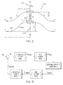
- FIG. 2 a schematic model 200 of an axially loaded buckling beam system coupled to linear compression springs 202 and 204 is depicted.
- Linear compression spring 202 can be a positive spring having a stiffness k p .
- a clamped-clamped boundary condition is depicted for a first buckling beam 210 and a second buckling beam 220. It is to be understood that a similar analysis for other boundary conditions can also be conducted and is within the scope of the disclosure. Further, a first buckling beam 210 and a second buckling beam 220 are shown to ensure uniform axial loading of the beams without inducing moments. However, it is to be understood that a single beam as well as two or more beams could also be used.
- half of the axial length of the first buckling beam 210 and the second buckling beam 220 is denoted as L, where D signifies a transverse deflection of the first and second buckling beams 210, 220.
- An effective axial load applied to the first and second buckling beams 210, 220 is represented with P, while a transverse loading is given as 2R.
- a path along the deflected first and second buckling beams 210, 220 is measured using the variable S and the angle ⁇ .
- the axial direction of the beams is denoted as X axial , with the vertical axis lying along the transverse direction (e.g. in the direction of the transverse load 2R).
- the inflection points of the first and second buckling beams 210 are identified as C 1 and C 2 .
- the illustrated deflection pattern is valid for small deflections and for axial loadings that are below a second critical buckling load.
- K b3 ((AE ⁇ / P cr (1+ ⁇ )) - 4/3((F/P cr (1 + ⁇ )) - 1)) ⁇ 4 .
- axial loading P a positive, zero, and negative transverse stiffness
- a compressive axial force applied to the beam exceeds the first critical buckling load P cr (e.g. K b1 > 0)
- buckling takes place and negative stiffness behavior of the beam can be observed.
- tensile axial loading e.g. K b1 ⁇ 0
- the beam possesses a positive transverse stiffness that increases as the tension load increases.
- the example control schematic can be used to control, vary, or otherwise modulate an effective stiffness of an actuator by determining a prescribed deflection of a member required to achieve a desired stiffness of the member, where the effective stiffness of the actuator is based at least in part on the stiffness of the member.
- the desired transverse stiffness can be selected, for example, according to a desired effective stiffness of the actuator.
- a current position e.g. X CURRENT
- a loading module that applies a load to the member
- the above noted axial stiffness model of the member e.g. K axial
- F CURRENT K axial ⁇ X CURRENT
- the current transverse stiffness e.g. K CURRENT
- the required change (+/-) in the transverse stiffness of the member e.g. ⁇ k
- the required change in force ⁇ F axial
- the required deflection ⁇ X axial
- the imparted deflection can be used to vary the transverse stiffness of the member which can be used to vary the effective stiffness of the actuator.
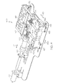
- a second example actuator 400 is provided with various example features that can be used either alone or in combination to vary an effective stiffness of the second example actuator 400.
- the second example actuator 400 can include an example end effector 415 and a linear positioning actuator 410 configured to position the actuator (e.g. control a position of the example end effector 415).
- the linear positioning actuator 410 can be controlled with a motor 412 (e.g. a DC motor) that drives a frame 413 along a direction shown by arrow 411.
- the frame 413 can be mounted on one or more linear sliders 431 and 432 to slide along the direction of motion 433 of the linear positioning actuator 410.
- the frame 413 can also include one or more loading actuators (e.g.
- first and second loading actuators 420, 422 can be configured to load one or more members or leaf springs (e.g. a first leaf spring 405 and a second leaf spring 406).
- first and second loading actuators 420, 422 can be configured to apply a load in a direction shown by arrows 421 and 423 corresponding to an axial direction of the first and second leaf springs 405, 406 which can vary a transverse stiffness of the first and second leaf springs 405, 406.
- Two loading actuators are used in a symmetrical manner to ensure uniform axial loading of the leaf springs without inducing moments on the leaf springs.
- one, two, three, or more leaf springs may also be used.
- the example end effector 415 can be connected to the leaf springs such that a change in stiffness (e.g. transverse stiffness) of the leaf springs changes an effective stiffness of the second example actuator 400 realized at the example end effector 415.
- Linear sliders 426 and 427 can be provided to enable (e.g. guide) the loading of the leaf springs 405, 406.
- the load can be a compressive axial load.
- the load can be a tensile axial load.
- the effective stiffness of the second example actuator 400 can be based at least in part on the transverse stiffness of the leaf springs 405, 406.
- a compressive axial load greater than a critical buckling load can cause the leaf springs to buckle and exhibit non-linear deflection characteristics of buckling (e.g. at least one of a zero transverse stiffness and a negative transverse stiffness).
- a tensile load can increase the transverse stiffness of the leaf springs (e.g. a positive transverse stiffness).
- a compression spring 425 can be attached to the leaf springs 405, 406 to set a nominal effective stiffness of the second example actuator 400.
- a linear optical encoder 407 can be provided to measure transverse deflection of the example end effector 415 with respect to the frame 413.
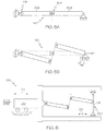
- a third example actuator 500 is provided with an effective stiffness based at least in part on non-linear deflection characteristics of tensile buckling.
- a third example member 501 can include a first rigid member 502 and a second rigid member 503.
- the first rigid member 502 and the second rigid member 503 can be connected by a sliding mechanism 505 (e.g. a slider).
- the first rigid member 502 can be pinned at one end to a support and can include a torsional spring 506 that imparts a rotational moment on the first rigid member 502.
- the third example member 501 under a tensile dead load F, the third example member 501 can buckle, and the relationship between the dead load F and the deflection of the member ( ⁇ x) will exhibit non-linear deflection characteristics of tensile buckling
- the effective stiffness of the third example actuator 500 can be based at least in part on the at least one of a zero stiffness and a negative stiffness of the third example member 501, including the first and second rigid members 502, 503 due to tensile buckling.
- the third example actuator 500 can further include a third example positioning module 510 having features the same as or similar to those of the first example positioning module 110 and can be configured to control a position of a third example end effector 515 along a direction shown by arrow 511.
- the third example actuator 500 can also include a third example loading module 520 having features the same as or similar to those of the first example loading module 120 and can be configured to apply a load to the third example member 501 (e.g. in a direction shown by arrow 521) to vary the effective stiffness of the third example actuator 500. It is also to be understood that the third example actuator 500 can include a third example controller 525 having features the same as or similar to those of the first example controller 102 described above and can be configured to implement the various methods of control, including but not limited to, force control of the third example actuator 500.
- a fourth example actuator 550 is provided with an effective stiffness based at least in part on non-linear deflection characteristics of tensile buckling.
- a fourth example member 551 can include a first bending member 552 and a second bending member 553.
- the first bending member 552 and the second bending member 553 can be connected by a sliding mechanism 555 (e.g. a slider).
- the first bending member 552 can be fixed at one end to a support.
- a sliding mechanism 555 e.g. a slider
- the fourth example member 551 under a tensile dead load F, the fourth example member 551 can buckle, and the relationship between the dead load F and the deflection of the fourth example member ( ⁇ x) will exhibit non-linear deflection characteristics of tensile buckling (e.g. at least one of a zero stiffness and a negative stiffness).
- the effective stiffness of the fourth example actuator 550 can be based at least in part on the at least one of a zero stiffness and a negative stiffness of the fourth example member 551, including the first and second bending members 552, 553 due to tensile buckling.
- the fourth example actuator 550 can further include a fourth example positioning module 560 having features the same as or similar to those of the first example positioning module 110 and the third example positioning module 510 and can be configured to control a position of a fourth example end effector 565 along a direction shown by arrow 561.
- the fourth example actuator 550 can also include a fourth example loading module 570 having features the same as or similar to those of the first example loading module 120 and the third example loading module 520 and can be configured to apply a load to the fourth example member 551 (e.g. in a direction shown by arrow 571) to vary the effective stiffness of the fourth example actuator 550.
- the fourth example actuator 550 can include a fourth example controller 575 having features the same as or similar to those of the first example controller 102 and the third example controller 525 described above and can be configured to implement the various methods of control, including but not limited to, force control of the fourth example actuator 550.
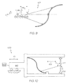
- FIG. 9 is an example schematic system 601 depicting buckling taking place under both compressive and tensile dead loading.
- the system will buckle under both compressive and tensile loading and the relationship between an applied load, accounting for a stiffness (k), and a corresponding displacement will exhibit non-linear deflection characteristics of buckling (e.g. at least one of a zero stiffness and a negative stiffness).
- the relationship between the load F T and the displacement ( ⁇ xT ) can produce negative stiffness.
- the relationship between the load F C and the corresponding displacement ( ⁇ xC ) can produce negative stiffness.
- the effective stiffness of the fifth example actuator 600 can be based at least in part on the negative stiffness of the system due to both compressive and tensile buckling.
- the fifth example actuator 600 can further include a fifth example positioning module 610 having features the same as or similar to those of the first example positioning module 110, the third example positioning module 510, and the fourth example positioning module 560 and can be configured to control a position of a fifth example end effector 615 along a direction shown by arrow 611.
- the fifth example actuator 600 can also include a fifth example loading module 620 having features the same as or similar to those of the first example loading module 120, the third example loading module 520, and the fourth example loading module 570 and can be configured to apply a load to the example schematic system 601 (e.g. in a direction shown by arrow 621) to vary the effective stiffness of the fifth example actuator 600.
- the fifth example actuator 600 can include a fifth example controller 602 having features the same as or similar to those of the first example controller 102, the third example controller 525, and the fourth example controller 575 described above and can be configured to implement the various methods of control, including but not limited to, force control of the fifth example actuator 600.
- a sixth example actuator 650 is provided with an effective stiffness (e.g. an effective rotary stiffness) based at least in part on non-linear deflection characteristics of torsional buckling.
- the sixth example actuator 650 can further include a sixth example positioning module 660 having features the same as or similar to those of the first example positioning module 110, the third example positioning module 510, the fourth example positioning module 560, and the fifth example positioning module 610 and can be configured to control a position of a sixth example end effector 665 by controlling a rotation of the sixth example positioning module 660 along a direction shown by arrow 661.
- the sixth example actuator 650 can also include a sixth example loading module 670 having features the same as or similar to those of the first example loading module 120, the third example loading module 520, the fourth example loading module 570, and the fifth example loading module 620 and can be configured to apply a load to an example beam 651 (e.g. in a direction shown by arrow 671) to vary the effective stiffness (e.g. an effective rotary stiffness) of the sixth example actuator 650.
- the effective stiffness e.g. an effective rotary stiffness
- a transverse stiffness of the beam decreases.
- the transverse stiffness of the beam can be controlled to include at least one of a zero stiffness and a negative stiffness.
- the effective rotary stiffness of the sixth example actuator 650 can be varied to include a positive, zero, and negative effective rotary stiffness.
- the sixth example actuator 650 can include a sixth example controller 652 having features the same as or similar to those of the first example controller 102, the third example controller 525, the fourth example controller 575, and the fifth example controller 602 described above and can be configured to implement the various methods of control, including but not limited to, force control of the sixth example actuator 650.
- the series implementation example actuator 700 can include a plurality of example members 701, 702, 703, 704 arranged in series with each other such that transverse deflection of each member can be superimposed.
- a load F applied axially to at least one of the plurality of members can cause the member to buckle and exhibit non-linear deflection characteristics of buckling.
- the effective stiffness (e.g. a stiffness at end effector 715) of the series implementation example actuator 700 can be based at least in part on the non-linear deflection characteristics of buckling according to the series implementation.
- the series implementation example actuator 700 can also include an optional spring 710 to set a nominal effective stiffness of the series implementation example actuator 700.
- the rotary implementation example actuator 800 can include an input disc 801 having a prescribed rotation represented as ⁇ d and a corresponding rotational stiffness.
- the rotary implementation example actuator 800 can further include one or more variable negative stiffness actuators 805 having features that are the same as or similar to the various example actuators described herein.
- the one or more variable negative stiffness actuators 805 can produce non-linear deflection characteristics of buckling which can define at least is part an effective rotational stiffness of an output disc 802 having a rotation ⁇ .
- the non-linear deflection characteristics of buckling can include buckling due to at least one of torsion, bending, compression, and tension, at least one of which can be used to vary the effective rotational stiffness of the rotary implementation example actuator 800.
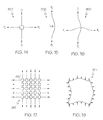
- FIGS. 14-18 illustrate other example implementations of variable negative stiffness actuation.
- a two-dimensional module 900 is provided, with out-of-plane buckling of the two-dimensional module 900 depicted in FIG. 15 , and in-plane buckling of the two-dimensional module 900 depicted in FIG. 16 .
- a two-dimensional matrix 910 is provided that includes a plurality of two-dimensional modules 900 arranged together.
- the two-dimensional matrix 910 can include multiple layers of modules.
- a continuous two-dimensional sheet 925 that can buckle and thus exhibit non-linear deflection characteristics of buckling is provided in FIG. 18 .
- Such two-dimensional stiffness modulation can be implemented to provide force feedback in surface devices, including but not limited to, phones, tablets, and other electronic devices.
Landscapes
- Engineering & Computer Science (AREA)
- Mechanical Engineering (AREA)
- Robotics (AREA)
- General Engineering & Computer Science (AREA)
- Manipulator (AREA)
- Mechanical Light Control Or Optical Switches (AREA)
- Endoscopes (AREA)
Applications Claiming Priority (2)
| Application Number | Priority Date | Filing Date | Title |
|---|---|---|---|
| US201361898755P | 2013-11-01 | 2013-11-01 | |
| US14/527,077 US10018238B2 (en) | 2013-11-01 | 2014-10-29 | Variable negative stiffness actuation |
Publications (3)
| Publication Number | Publication Date |
|---|---|
| EP2868923A2 true EP2868923A2 (fr) | 2015-05-06 |
| EP2868923A3 EP2868923A3 (fr) | 2016-01-20 |
| EP2868923B1 EP2868923B1 (fr) | 2022-02-09 |
Family
ID=51947115
Family Applications (1)
| Application Number | Title | Priority Date | Filing Date |
|---|---|---|---|
| EP14191185.9A Active EP2868923B1 (fr) | 2013-11-01 | 2014-10-30 | Actionnement de rigidité négative variable |
Country Status (3)
| Country | Link |
|---|---|
| US (1) | US10018238B2 (fr) |
| EP (1) | EP2868923B1 (fr) |
| JP (1) | JP6164615B2 (fr) |
Cited By (2)
| Publication number | Priority date | Publication date | Assignee | Title |
|---|---|---|---|---|
| CN110139996A (zh) * | 2017-01-12 | 2019-08-16 | Hrl实验室有限责任公司 | 可调节负刚度机构 |
| CN111577806A (zh) * | 2020-06-01 | 2020-08-25 | 中国船舶科学研究中心 | 一种正负刚度并联式低频隔振器 |
Families Citing this family (9)
| Publication number | Priority date | Publication date | Assignee | Title |
|---|---|---|---|---|
| JP6276090B2 (ja) * | 2014-03-31 | 2018-02-07 | 株式会社ダイヘン | 搬送装置、搬送システム |
| JP6980660B2 (ja) * | 2015-12-15 | 2021-12-15 | カール・ツァイス・エスエムティー・ゲーエムベーハー | リソグラフィ装置用の光学デバイス及びリソグラフィ装置 |
| US10634870B2 (en) | 2016-02-19 | 2020-04-28 | Goodrich Corporation | Actuator devices for converting rotational input to linear output |
| US10260586B2 (en) * | 2017-01-12 | 2019-04-16 | Hrl Laboratories, Llc | Adjustable negative stiffness systems |
| US10483138B2 (en) * | 2017-03-09 | 2019-11-19 | Himax Technologies Limited | Wafer clamp and a method of clamping a wafer |
| CN110948504B (zh) * | 2020-02-20 | 2020-06-19 | 中科新松有限公司 | 机器人加工作业法向恒力跟踪方法和装置 |
| CN111550522B (zh) * | 2020-05-19 | 2022-08-12 | 集美大学 | 一种带高静低动刚度振子周期结构的船舶推进轴系 |
| WO2023167652A1 (fr) | 2022-03-01 | 2023-09-07 | Sabanci Üniversitesi | Sac à dos à charge suspendue comportant un système de suspension à impédance réglable |
| CN114918963A (zh) * | 2022-05-31 | 2022-08-19 | 三一汽车制造有限公司 | 一种吸盘机构及桁架机械手 |
Family Cites Families (11)
| Publication number | Priority date | Publication date | Assignee | Title |
|---|---|---|---|---|
| US5370352A (en) * | 1989-08-16 | 1994-12-06 | Minus K Technology, Inc. | Damped vibration isolation system |
| US5833204A (en) * | 1989-08-16 | 1998-11-10 | Minus K Technology, Inc. | Radial flextures, Beam-Columns and tilt isolation for a vibration isolation system |
| US5310157A (en) * | 1989-08-16 | 1994-05-10 | Minus K Technology, Inc. | Vibration isolation system |
| JPH063529U (ja) | 1992-06-24 | 1994-01-18 | 株式会社木下機械製作所 | 精密部品組立て用誤差修正機構 |
| KR100251625B1 (ko) | 1997-12-27 | 2000-04-15 | 정문술 | 모듈아이씨(ic)용핸들러의모듈ic홀딩장치 |
| US6739132B2 (en) | 2002-04-30 | 2004-05-25 | Adc Telecommunications, Inc. | Thermal micro-actuator based on selective electrical excitation |
| US6753582B2 (en) * | 2002-08-14 | 2004-06-22 | Intel Corporation | Buckling beam bi-stable microelectromechanical switch using electro-thermal actuation |
| US20060253099A1 (en) * | 2005-04-21 | 2006-11-09 | Medtronic Vascular, Inc. | Guiding catheter with resiliently compressible occluder |
| US8232858B1 (en) | 2008-02-20 | 2012-07-31 | Sandia Corporation | Microelectromechanical (MEM) thermal actuator |
| JP2011083884A (ja) | 2009-10-19 | 2011-04-28 | Yaskawa Electric Corp | 可変剛性機構及びロボット |
| WO2011059956A2 (fr) * | 2009-11-10 | 2011-05-19 | Massachusetts Institute Of Technology | Actionneur de flambage à groupement phasé |
-
2014
- 2014-10-29 US US14/527,077 patent/US10018238B2/en active Active
- 2014-10-30 EP EP14191185.9A patent/EP2868923B1/fr active Active
- 2014-10-31 JP JP2014222790A patent/JP6164615B2/ja active Active
Non-Patent Citations (1)
| Title |
|---|
| None |
Cited By (4)
| Publication number | Priority date | Publication date | Assignee | Title |
|---|---|---|---|---|
| CN110139996A (zh) * | 2017-01-12 | 2019-08-16 | Hrl实验室有限责任公司 | 可调节负刚度机构 |
| CN110139996B (zh) * | 2017-01-12 | 2022-04-19 | Hrl实验室有限责任公司 | 可调节负刚度机构 |
| CN111577806A (zh) * | 2020-06-01 | 2020-08-25 | 中国船舶科学研究中心 | 一种正负刚度并联式低频隔振器 |
| CN111577806B (zh) * | 2020-06-01 | 2022-02-18 | 中国船舶科学研究中心 | 一种正负刚度并联式低频隔振器 |
Also Published As
| Publication number | Publication date |
|---|---|
| JP6164615B2 (ja) | 2017-07-19 |
| EP2868923B1 (fr) | 2022-02-09 |
| US10018238B2 (en) | 2018-07-10 |
| US20150123417A1 (en) | 2015-05-07 |
| EP2868923A3 (fr) | 2016-01-20 |
| JP2015110261A (ja) | 2015-06-18 |
Similar Documents
| Publication | Publication Date | Title |
|---|---|---|
| US10018238B2 (en) | Variable negative stiffness actuation | |
| Tolman et al. | Compliant constant-force linear-motion mechanism | |
| EP1993007B1 (fr) | Procede de commande et dispositif de commande de mecanisme de positionnement | |
| Hau et al. | Performance prediction and scaling laws of circular dielectric elastomer membrane actuators | |
| Wang et al. | Design and optimization of a new compliant rotary positioning stage with constant output torque | |
| Yun et al. | Microscale position control of an electroactive polymer using an anti-windup scheme | |
| Li et al. | Dynamic linear modeling, identification and precise control of a walking piezo-actuated stage | |
| CN107834897B (zh) | 基于压电驱动的爬行作动器及其工作方法 | |
| JP6442386B2 (ja) | 力制御装置 | |
| Liu et al. | Design, analysis, and experimental validation of an active constant-force system based on a low-stiffness mechanism | |
| JP5821581B2 (ja) | 耐久試験装置 | |
| Kang | Compliance characteristic and force control of antagonistic actuation by pneumatic artificial muscles | |
| Yalcin et al. | VnSA: Variable negative stiffness actuation based on nonlinear deflection characteristics of buckling beams | |
| Cortopassi et al. | Nonlinear springs for increasing the maximum stable deflection of MEMS electrostatic gap closing actuators | |
| JP5353767B2 (ja) | 耐久試験装置 | |
| CN110561427A (zh) | 一种基于补偿的串联弹性驱动器柔顺控制系统及方法 | |
| Golubovic et al. | Adaptive control of piezoelectric walker actuator | |
| US11911897B2 (en) | Mechanically over-damped actuators having adjustable stiffness | |
| Elliott et al. | Model predictive control of vibration in a two flexible link manipulator—Part I | |
| KR101999057B1 (ko) | 직렬 탄성 액추에이터 및 이를 포함하는 제어기 | |
| Choi et al. | H∞ control of a flexible gantry robot arm using smart actuators | |
| Avram et al. | On improving the performances of pneumatic positioning systems | |
| Ouwehand | Novel nanometer precision planar positioning stage using pre-sliding friction | |
| NL1038896C2 (en) | Inertial drive system with friction release. | |
| Kubus et al. | Adaptronic couplers—an alternative drive principle |
Legal Events
| Date | Code | Title | Description |
|---|---|---|---|
| PUAI | Public reference made under article 153(3) epc to a published international application that has entered the european phase |
Free format text: ORIGINAL CODE: 0009012 |
|
| 17P | Request for examination filed |
Effective date: 20141030 |
|
| AK | Designated contracting states |
Kind code of ref document: A2 Designated state(s): AL AT BE BG CH CY CZ DE DK EE ES FI FR GB GR HR HU IE IS IT LI LT LU LV MC MK MT NL NO PL PT RO RS SE SI SK SM TR |
|
| AX | Request for extension of the european patent |
Extension state: BA ME |
|
| PUAL | Search report despatched |
Free format text: ORIGINAL CODE: 0009013 |
|
| AK | Designated contracting states |
Kind code of ref document: A3 Designated state(s): AL AT BE BG CH CY CZ DE DK EE ES FI FR GB GR HR HU IE IS IT LI LT LU LV MC MK MT NL NO PL PT RO RS SE SI SK SM TR |
|
| AX | Request for extension of the european patent |
Extension state: BA ME |
|
| RIC1 | Information provided on ipc code assigned before grant |
Ipc: F03G 7/06 20060101AFI20151216BHEP |
|
| R17P | Request for examination filed (corrected) |
Effective date: 20160712 |
|
| RBV | Designated contracting states (corrected) |
Designated state(s): AL AT BE BG CH CY CZ DE DK EE ES FI FR GB GR HR HU IE IS IT LI LT LU LV MC MK MT NL NO PL PT RO RS SE SI SK SM TR |
|
| STAA | Information on the status of an ep patent application or granted ep patent |
Free format text: STATUS: EXAMINATION IS IN PROGRESS |
|
| 17Q | First examination report despatched |
Effective date: 20200814 |
|
| STAA | Information on the status of an ep patent application or granted ep patent |
Free format text: STATUS: EXAMINATION IS IN PROGRESS |
|
| STAA | Information on the status of an ep patent application or granted ep patent |
Free format text: STATUS: EXAMINATION IS IN PROGRESS |
|
| GRAP | Despatch of communication of intention to grant a patent |
Free format text: ORIGINAL CODE: EPIDOSNIGR1 |
|
| STAA | Information on the status of an ep patent application or granted ep patent |
Free format text: STATUS: GRANT OF PATENT IS INTENDED |
|
| INTG | Intention to grant announced |
Effective date: 20210728 |
|
| GRAS | Grant fee paid |
Free format text: ORIGINAL CODE: EPIDOSNIGR3 |
|
| GRAJ | Information related to disapproval of communication of intention to grant by the applicant or resumption of examination proceedings by the epo deleted |
Free format text: ORIGINAL CODE: EPIDOSDIGR1 |
|
| GRAL | Information related to payment of fee for publishing/printing deleted |
Free format text: ORIGINAL CODE: EPIDOSDIGR3 |
|
| STAA | Information on the status of an ep patent application or granted ep patent |
Free format text: STATUS: EXAMINATION IS IN PROGRESS |
|
| GRAP | Despatch of communication of intention to grant a patent |
Free format text: ORIGINAL CODE: EPIDOSNIGR1 |
|
| STAA | Information on the status of an ep patent application or granted ep patent |
Free format text: STATUS: GRANT OF PATENT IS INTENDED |
|
| INTC | Intention to grant announced (deleted) | ||
| GRAA | (expected) grant |
Free format text: ORIGINAL CODE: 0009210 |
|
| STAA | Information on the status of an ep patent application or granted ep patent |
Free format text: STATUS: THE PATENT HAS BEEN GRANTED |
|
| INTG | Intention to grant announced |
Effective date: 20211217 |
|
| AK | Designated contracting states |
Kind code of ref document: B1 Designated state(s): AL AT BE BG CH CY CZ DE DK EE ES FI FR GB GR HR HU IE IS IT LI LT LU LV MC MK MT NL NO PL PT RO RS SE SI SK SM TR |
|
| REG | Reference to a national code |
Ref country code: GB Ref legal event code: FG4D |
|
| REG | Reference to a national code |
Ref country code: CH Ref legal event code: EP Ref country code: AT Ref legal event code: REF Ref document number: 1467659 Country of ref document: AT Kind code of ref document: T Effective date: 20220215 |
|
| REG | Reference to a national code |
Ref country code: IE Ref legal event code: FG4D |
|
| REG | Reference to a national code |
Ref country code: DE Ref legal event code: R096 Ref document number: 602014082424 Country of ref document: DE |
|
| REG | Reference to a national code |
Ref country code: LT Ref legal event code: MG9D |
|
| REG | Reference to a national code |
Ref country code: NL Ref legal event code: MP Effective date: 20220209 |
|
| REG | Reference to a national code |
Ref country code: AT Ref legal event code: MK05 Ref document number: 1467659 Country of ref document: AT Kind code of ref document: T Effective date: 20220209 |
|
| PG25 | Lapsed in a contracting state [announced via postgrant information from national office to epo] |
Ref country code: SE Free format text: LAPSE BECAUSE OF FAILURE TO SUBMIT A TRANSLATION OF THE DESCRIPTION OR TO PAY THE FEE WITHIN THE PRESCRIBED TIME-LIMIT Effective date: 20220209 Ref country code: RS Free format text: LAPSE BECAUSE OF FAILURE TO SUBMIT A TRANSLATION OF THE DESCRIPTION OR TO PAY THE FEE WITHIN THE PRESCRIBED TIME-LIMIT Effective date: 20220209 Ref country code: PT Free format text: LAPSE BECAUSE OF FAILURE TO SUBMIT A TRANSLATION OF THE DESCRIPTION OR TO PAY THE FEE WITHIN THE PRESCRIBED TIME-LIMIT Effective date: 20220609 Ref country code: NO Free format text: LAPSE BECAUSE OF FAILURE TO SUBMIT A TRANSLATION OF THE DESCRIPTION OR TO PAY THE FEE WITHIN THE PRESCRIBED TIME-LIMIT Effective date: 20220509 Ref country code: NL Free format text: LAPSE BECAUSE OF FAILURE TO SUBMIT A TRANSLATION OF THE DESCRIPTION OR TO PAY THE FEE WITHIN THE PRESCRIBED TIME-LIMIT Effective date: 20220209 Ref country code: LT Free format text: LAPSE BECAUSE OF FAILURE TO SUBMIT A TRANSLATION OF THE DESCRIPTION OR TO PAY THE FEE WITHIN THE PRESCRIBED TIME-LIMIT Effective date: 20220209 Ref country code: HR Free format text: LAPSE BECAUSE OF FAILURE TO SUBMIT A TRANSLATION OF THE DESCRIPTION OR TO PAY THE FEE WITHIN THE PRESCRIBED TIME-LIMIT Effective date: 20220209 Ref country code: ES Free format text: LAPSE BECAUSE OF FAILURE TO SUBMIT A TRANSLATION OF THE DESCRIPTION OR TO PAY THE FEE WITHIN THE PRESCRIBED TIME-LIMIT Effective date: 20220209 Ref country code: BG Free format text: LAPSE BECAUSE OF FAILURE TO SUBMIT A TRANSLATION OF THE DESCRIPTION OR TO PAY THE FEE WITHIN THE PRESCRIBED TIME-LIMIT Effective date: 20220509 |
|
| PG25 | Lapsed in a contracting state [announced via postgrant information from national office to epo] |
Ref country code: PL Free format text: LAPSE BECAUSE OF FAILURE TO SUBMIT A TRANSLATION OF THE DESCRIPTION OR TO PAY THE FEE WITHIN THE PRESCRIBED TIME-LIMIT Effective date: 20220209 Ref country code: LV Free format text: LAPSE BECAUSE OF FAILURE TO SUBMIT A TRANSLATION OF THE DESCRIPTION OR TO PAY THE FEE WITHIN THE PRESCRIBED TIME-LIMIT Effective date: 20220209 Ref country code: GR Free format text: LAPSE BECAUSE OF FAILURE TO SUBMIT A TRANSLATION OF THE DESCRIPTION OR TO PAY THE FEE WITHIN THE PRESCRIBED TIME-LIMIT Effective date: 20220510 Ref country code: FI Free format text: LAPSE BECAUSE OF FAILURE TO SUBMIT A TRANSLATION OF THE DESCRIPTION OR TO PAY THE FEE WITHIN THE PRESCRIBED TIME-LIMIT Effective date: 20220209 Ref country code: AT Free format text: LAPSE BECAUSE OF FAILURE TO SUBMIT A TRANSLATION OF THE DESCRIPTION OR TO PAY THE FEE WITHIN THE PRESCRIBED TIME-LIMIT Effective date: 20220209 |
|
| PG25 | Lapsed in a contracting state [announced via postgrant information from national office to epo] |
Ref country code: IS Free format text: LAPSE BECAUSE OF FAILURE TO SUBMIT A TRANSLATION OF THE DESCRIPTION OR TO PAY THE FEE WITHIN THE PRESCRIBED TIME-LIMIT Effective date: 20220609 |
|
| PG25 | Lapsed in a contracting state [announced via postgrant information from national office to epo] |
Ref country code: SM Free format text: LAPSE BECAUSE OF FAILURE TO SUBMIT A TRANSLATION OF THE DESCRIPTION OR TO PAY THE FEE WITHIN THE PRESCRIBED TIME-LIMIT Effective date: 20220209 Ref country code: SK Free format text: LAPSE BECAUSE OF FAILURE TO SUBMIT A TRANSLATION OF THE DESCRIPTION OR TO PAY THE FEE WITHIN THE PRESCRIBED TIME-LIMIT Effective date: 20220209 Ref country code: RO Free format text: LAPSE BECAUSE OF FAILURE TO SUBMIT A TRANSLATION OF THE DESCRIPTION OR TO PAY THE FEE WITHIN THE PRESCRIBED TIME-LIMIT Effective date: 20220209 Ref country code: EE Free format text: LAPSE BECAUSE OF FAILURE TO SUBMIT A TRANSLATION OF THE DESCRIPTION OR TO PAY THE FEE WITHIN THE PRESCRIBED TIME-LIMIT Effective date: 20220209 Ref country code: DK Free format text: LAPSE BECAUSE OF FAILURE TO SUBMIT A TRANSLATION OF THE DESCRIPTION OR TO PAY THE FEE WITHIN THE PRESCRIBED TIME-LIMIT Effective date: 20220209 Ref country code: CZ Free format text: LAPSE BECAUSE OF FAILURE TO SUBMIT A TRANSLATION OF THE DESCRIPTION OR TO PAY THE FEE WITHIN THE PRESCRIBED TIME-LIMIT Effective date: 20220209 |
|
| REG | Reference to a national code |
Ref country code: DE Ref legal event code: R097 Ref document number: 602014082424 Country of ref document: DE |
|
| PG25 | Lapsed in a contracting state [announced via postgrant information from national office to epo] |
Ref country code: AL Free format text: LAPSE BECAUSE OF FAILURE TO SUBMIT A TRANSLATION OF THE DESCRIPTION OR TO PAY THE FEE WITHIN THE PRESCRIBED TIME-LIMIT Effective date: 20220209 |
|
| PLBE | No opposition filed within time limit |
Free format text: ORIGINAL CODE: 0009261 |
|
| STAA | Information on the status of an ep patent application or granted ep patent |
Free format text: STATUS: NO OPPOSITION FILED WITHIN TIME LIMIT |
|
| 26N | No opposition filed |
Effective date: 20221110 |
|
| PG25 | Lapsed in a contracting state [announced via postgrant information from national office to epo] |
Ref country code: SI Free format text: LAPSE BECAUSE OF FAILURE TO SUBMIT A TRANSLATION OF THE DESCRIPTION OR TO PAY THE FEE WITHIN THE PRESCRIBED TIME-LIMIT Effective date: 20220209 |
|
| PG25 | Lapsed in a contracting state [announced via postgrant information from national office to epo] |
Ref country code: MC Free format text: LAPSE BECAUSE OF FAILURE TO SUBMIT A TRANSLATION OF THE DESCRIPTION OR TO PAY THE FEE WITHIN THE PRESCRIBED TIME-LIMIT Effective date: 20220209 |
|
| REG | Reference to a national code |
Ref country code: CH Ref legal event code: PL |
|
| REG | Reference to a national code |
Ref country code: BE Ref legal event code: MM Effective date: 20221031 |
|
| PG25 | Lapsed in a contracting state [announced via postgrant information from national office to epo] |
Ref country code: LU Free format text: LAPSE BECAUSE OF NON-PAYMENT OF DUE FEES Effective date: 20221030 |
|
| PG25 | Lapsed in a contracting state [announced via postgrant information from national office to epo] |
Ref country code: LI Free format text: LAPSE BECAUSE OF NON-PAYMENT OF DUE FEES Effective date: 20221031 Ref country code: IT Free format text: LAPSE BECAUSE OF FAILURE TO SUBMIT A TRANSLATION OF THE DESCRIPTION OR TO PAY THE FEE WITHIN THE PRESCRIBED TIME-LIMIT Effective date: 20220209 Ref country code: CH Free format text: LAPSE BECAUSE OF NON-PAYMENT OF DUE FEES Effective date: 20221031 |
|
| PG25 | Lapsed in a contracting state [announced via postgrant information from national office to epo] |
Ref country code: BE Free format text: LAPSE BECAUSE OF NON-PAYMENT OF DUE FEES Effective date: 20221031 |
|
| PG25 | Lapsed in a contracting state [announced via postgrant information from national office to epo] |
Ref country code: IE Free format text: LAPSE BECAUSE OF NON-PAYMENT OF DUE FEES Effective date: 20221030 |
|
| PGFP | Annual fee paid to national office [announced via postgrant information from national office to epo] |
Ref country code: GB Payment date: 20231120 Year of fee payment: 10 |
|
| PGFP | Annual fee paid to national office [announced via postgrant information from national office to epo] |
Ref country code: TR Payment date: 20231017 Year of fee payment: 10 Ref country code: FR Payment date: 20231031 Year of fee payment: 10 Ref country code: DE Payment date: 20231107 Year of fee payment: 10 |
|
| PG25 | Lapsed in a contracting state [announced via postgrant information from national office to epo] |
Ref country code: HU Free format text: LAPSE BECAUSE OF FAILURE TO SUBMIT A TRANSLATION OF THE DESCRIPTION OR TO PAY THE FEE WITHIN THE PRESCRIBED TIME-LIMIT; INVALID AB INITIO Effective date: 20141030 |
|
| PG25 | Lapsed in a contracting state [announced via postgrant information from national office to epo] |
Ref country code: CY Free format text: LAPSE BECAUSE OF FAILURE TO SUBMIT A TRANSLATION OF THE DESCRIPTION OR TO PAY THE FEE WITHIN THE PRESCRIBED TIME-LIMIT Effective date: 20220209 |
|
| PG25 | Lapsed in a contracting state [announced via postgrant information from national office to epo] |
Ref country code: MK Free format text: LAPSE BECAUSE OF FAILURE TO SUBMIT A TRANSLATION OF THE DESCRIPTION OR TO PAY THE FEE WITHIN THE PRESCRIBED TIME-LIMIT Effective date: 20220209 |
|
| PG25 | Lapsed in a contracting state [announced via postgrant information from national office to epo] |
Ref country code: MT Free format text: LAPSE BECAUSE OF FAILURE TO SUBMIT A TRANSLATION OF THE DESCRIPTION OR TO PAY THE FEE WITHIN THE PRESCRIBED TIME-LIMIT Effective date: 20220209 |