EP2868876B1 - Integrierte Motorbremse - Google Patents
Integrierte Motorbremse Download PDFInfo
- Publication number
- EP2868876B1 EP2868876B1 EP13196579.0A EP13196579A EP2868876B1 EP 2868876 B1 EP2868876 B1 EP 2868876B1 EP 13196579 A EP13196579 A EP 13196579A EP 2868876 B1 EP2868876 B1 EP 2868876B1
- Authority
- EP
- European Patent Office
- Prior art keywords
- oil
- rocker arm
- bridge
- exhaust rocker
- exhaust
- Prior art date
- Legal status (The legal status is an assumption and is not a legal conclusion. Google has not performed a legal analysis and makes no representation as to the accuracy of the status listed.)
- Not-in-force
Links
- 230000006835 compression Effects 0.000 claims description 16
- 238000007906 compression Methods 0.000 claims description 16
- 238000002485 combustion reaction Methods 0.000 claims description 7
- 238000009792 diffusion process Methods 0.000 claims description 7
- 239000003921 oil Substances 0.000 description 82
- 230000007246 mechanism Effects 0.000 description 10
- 239000010705 motor oil Substances 0.000 description 10
- 230000003247 decreasing effect Effects 0.000 description 8
- 239000000446 fuel Substances 0.000 description 7
- 230000006872 improvement Effects 0.000 description 6
- 230000004048 modification Effects 0.000 description 3
- 238000012986 modification Methods 0.000 description 3
- 230000009467 reduction Effects 0.000 description 3
- 230000009471 action Effects 0.000 description 2
- 230000000694 effects Effects 0.000 description 2
- 238000004880 explosion Methods 0.000 description 2
- 230000004913 activation Effects 0.000 description 1
- 239000000567 combustion gas Substances 0.000 description 1
- 230000001419 dependent effect Effects 0.000 description 1
- 238000007599 discharging Methods 0.000 description 1
- 239000007789 gas Substances 0.000 description 1
- 239000011796 hollow space material Substances 0.000 description 1
- 238000000034 method Methods 0.000 description 1
Images


Classifications
-
- F—MECHANICAL ENGINEERING; LIGHTING; HEATING; WEAPONS; BLASTING
- F01—MACHINES OR ENGINES IN GENERAL; ENGINE PLANTS IN GENERAL; STEAM ENGINES
- F01L—CYCLICALLY OPERATING VALVES FOR MACHINES OR ENGINES
- F01L13/00—Modifications of valve-gear to facilitate reversing, braking, starting, changing compression ratio, or other specific operations
- F01L13/06—Modifications of valve-gear to facilitate reversing, braking, starting, changing compression ratio, or other specific operations for braking
-
- F—MECHANICAL ENGINEERING; LIGHTING; HEATING; WEAPONS; BLASTING
- F01—MACHINES OR ENGINES IN GENERAL; ENGINE PLANTS IN GENERAL; STEAM ENGINES
- F01L—CYCLICALLY OPERATING VALVES FOR MACHINES OR ENGINES
- F01L13/00—Modifications of valve-gear to facilitate reversing, braking, starting, changing compression ratio, or other specific operations
- F01L13/06—Modifications of valve-gear to facilitate reversing, braking, starting, changing compression ratio, or other specific operations for braking
- F01L13/065—Compression release engine retarders of the "Jacobs Manufacturing" type
-
- F—MECHANICAL ENGINEERING; LIGHTING; HEATING; WEAPONS; BLASTING
- F01—MACHINES OR ENGINES IN GENERAL; ENGINE PLANTS IN GENERAL; STEAM ENGINES
- F01L—CYCLICALLY OPERATING VALVES FOR MACHINES OR ENGINES
- F01L1/00—Valve-gear or valve arrangements, e.g. lift-valve gear
- F01L1/26—Valve-gear or valve arrangements, e.g. lift-valve gear characterised by the provision of two or more valves operated simultaneously by same transmitting-gear; peculiar to machines or engines with more than two lift-valves per cylinder
- F01L1/267—Valve-gear or valve arrangements, e.g. lift-valve gear characterised by the provision of two or more valves operated simultaneously by same transmitting-gear; peculiar to machines or engines with more than two lift-valves per cylinder with means for varying the timing or the lift of the valves
-
- F—MECHANICAL ENGINEERING; LIGHTING; HEATING; WEAPONS; BLASTING
- F02—COMBUSTION ENGINES; HOT-GAS OR COMBUSTION-PRODUCT ENGINE PLANTS
- F02D—CONTROLLING COMBUSTION ENGINES
- F02D13/00—Controlling the engine output power by varying inlet or exhaust valve operating characteristics, e.g. timing
- F02D13/02—Controlling the engine output power by varying inlet or exhaust valve operating characteristics, e.g. timing during engine operation
- F02D13/04—Controlling the engine output power by varying inlet or exhaust valve operating characteristics, e.g. timing during engine operation using engine as brake
Definitions
- Exemplary embodiments of the present invention relate to an engine brake and, more particularly, to an integrated engine brake in which a structure associated with a valve mechanism such as an exhaust rocker arm or a cam shaft is formed, thereby decreasing a size along with weight to provide a more compact configuration.
- a valve mechanism such as an exhaust rocker arm or a cam shaft
- Such auxiliary brakes are based on a principle in which power transmitted to a crankshaft during intake-compression-expansion-exhaust strokes of combustion strokes of an engine is reduced to further secure the braking force.
- the auxiliary brakes may include an engine brake, a jake brake, and an exhaust brake by way of example.
- the engine brake has a mode in which vacuum pressure resistance applied to a piston during an intake stroke, compression resistance during a compression stroke, compression resistance during an exhaust stroke, and a mechanical frictional force generated when the engine rotates are used as a braking force.
- a driving force of a vehicle is generated during typical travelling in which the intake-compression-explosion-exhaust strokes are normally performed, but an exhaust valve is forcibly opened at a compression top dead center while an accelerator pedal is released, and thereby the vehicle is decelerated.
- the engine brakes are formed on an upper portion of the engine along with a valve mechanism, and circulate oil to operate an exhaust rocker arm when activated.
- the exhaust rocker arm presses the exhaust valve, and thereby an exhaust gas in a combustion chamber is forcibly discharged.
- the engine brakes are not at all structurally associated with the valve mechanism such as the rocker arm or the cam shaft while controlling the operation of the rocker arm of the valve mechanism on the upper portion of the engine, are manufactured as a separate assembly, and are installed on the upper portion of the engine so that the manufactured separate assembly is connected to the valve mechanism.
- Document EP 2439381 A1 shows an engine braking apparatus having a cam, a rocker arm, a valve bridge and braking pistons.
- Document EP 2 677 127 A1 prior art under Art. 54(3) EPC, shows an engine brake having a braking actuation mechanism, braking pistons, a valve bridge and an oil passage. Further engine brake apparatuses are shown in documents US 2010/170471 A1 , DE 10 2006 054312 A1 , US 2005/211206 A1 and WO 2010/141633 A1 .
- Various aspects of the present invention are directed to providing an integrated engine brake in which an oil channel is formed using an exhaust rocker arm configured to activate an exhaust valve during an exhaust stroke, and thereby weight is reduced along with a size, and can be easily applied to a commercial vehicle engine which has high horsepower and high torque, which is decreased in size, and in which the exhaust regulation and the improvement of fuel efficiency are required, due to a compact configuration resulting from the reduction in weight and size.
- the present invention provides an integrated engine brake according to claim 1. Further advantageous embodiments are set out in the dependent claims.
- the oil outlet may be formed in an adjustor bolt, and the adjustor bolt may be coupled to the exhaust rocker arm and come into contact with the bridge.
- the oil outlet may be formed in an internal space of the adjustor bolt in an axial direction, and the oil outlet may communicate with the oil flow path through a circumferential hole of the adjustor bolt.
- the chamber may include a plug having a plug chamber oil inlet into which the oil discharged from the oil outlet flows, and which discharges the oil to the chamber.
- the pair of first and second master pistons may be housed in the pair of first and second piston chambers in which the oil pressure is formed, and the pair of first and second piston chambers may be connected to a pair of first and second oil diffusion paths which extend toward both of left and right ends of the chamber.
- the exhaust rocker arm may further include a bias spring, and the bias spring presses the exhaust rocker arm so that the adjustor bolt coupled to the exhaust rocker arm comes into contact with the bridge.
- the protrusion may be located on a lower portion of the exhaust rocker arm, and protrude from an outer circumferential surface of a rotated exhaust cam.
- the protrusion may come into contact with an exhaust rocker arm roller, and the exhaust rocker arm roller may be formed on the exhaust rocker arm.
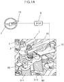
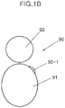
- FIGS. 1A and 1B show a configuration of an integrated engine brake according to an exemplary embodiment of the present invention.
- the engine brake includes an engine brake lever 10, an oil supply member 20, an adjustor bolt 50, a bridge 60, a bias spring 70, a reset bar 80, and a lifter 90.
- the engine brake lever 10 is installed on a steering wheel 7 and generates an On/Off signal.
- the oil supply member 20 forms a flow path in which engine oil flows through an exhaust rocker arm 3 when the engine brake lever 10 is switched on.
- the exhaust rocker arm 3 is a member of a valve mechanism 1 that is installed on an upper portion of the engine and opens/closes a pair of first and second exhaust valves 5-1 and 5-2 installed on each cylinder of the engine.
- the adjustor bolt 50 is cooperated with movement of the exhaust rocker arm 3 and functions as a path through the engine oil supplied from the oil supply member 20 is discharged to the bridge 60.
- the bridge 60 presses the pair of first and second exhaust valves 5-1 and 5-2 due to an action of the introduced engine oil, thereby forcibly discharging a combustion gas within the cylinder.
- the bias spring 70 presses the exhaust rocker arm 3 so that the adjustor bolt 50 and the bridge 60 are brought into contact with each other.
- the reset bar 80 is located on a lower portion of the bridge 60 so as to discharge the engine oil within the bridge 60 at a predetermined point in time.
- the lifter 90 raises the exhaust rocker arm 3 at a compression top dead center.
- the lifter 90 includes an exhaust cam 91, an exhaust rocker arm roller 93, and a protrusion 90-1 installed between them, and the protrusion 90-1 protrudes from an outer circumferential surface of the exhaust cam 91 at a position of the compression top dead center.
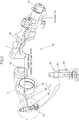
- FIG. 2 shows a detailed configuration of the oil supply member 20.
- the oil supply member 20 includes a valve 30 that opens an engine oil flow path 4a when the engine brake lever 10 is operated, and an internal oil flow path 40 that forms a path of the introduced engine oil.
- the valve 30 blocks the engine oil flow path 4a of a rocker arm shaft 4 and then opens the engine oil flow path 4a when the engine brake lever 10 is operated.
- a solenoid type is applied to the valve 30.
- the internal oil flow path 40 includes an oil inlet 41, an oil flow path 43, and an oil outlet 45.
- the oil inlet 41 is formed in a shaft hole of the exhaust rocker arm 3 to which the rocker arm shaft 4 is coupled.
- the oil flow path 43 is formed inside the exhaust rocker arm 3 so that the oil flowing into the oil inlet 41 flows to an end portion of the exhaust rocker arm 3, and the oil outlet 45 is formed in the adjustor bolt 50 so that the oil is discharged through the adjustor bolt 50.
- the oil flow path 43 has an end connected to a joint of the adjustor bolt 50.
- the oil outlet 45 is formed in an internal space of a bolt shank 51 of the adjustor bolt 50 in an axial direction, and has an inlet communicating with the oil flow path 43 through a circumferential hole of the bolt shank 51 and an outlet connected to the bridge 60.
- FIG. 3 shows a detailed configuration of the bridge 60.
- the bridge 60 includes a bridge body 61 in which a chamber is formed by an inner hollow space, a plug 62 that has a plug chamber oil inlet 62-1 into which the oil of the oil supply member 20 flows and a plug chamber 61-1 of the bridge body 61, a pair of first and second master pistons 67-1 and 67-2 which are located at both left and right sides of the bridge body 61 and to which a pressure of the oil flowing from the plug chamber oil inlet 62-1 into the chamber is applied, and a reset pin 69 that is installed on a lower portion of the bridge body 61 so that the oil of the chamber is discharged to the outside.
- the chamber of the bridge body 61 includes the plug chamber 61-1 into which the plug 62 is inserted, a pair of first and second oil diffusion paths 63-1 and 63-2 that extend toward the pair of first and second master pistons 67-1 and 67-2 at left and right sides of the plug chamber 61-1, and a pair of first and second piston chambers 65-1 and 65-2 that are formed in ends of the pair of first and second oil diffusion paths 63-1 and 63-2 so that the pair of first and second master pistons 67-1 and 67-2 are housed therein.
- the plug chamber oil inlet 62-1 of the plug 62 communicates with the plug chamber 61-1.
- first master piston 67-1 presses the first exhaust valve 5-1
- second master piston 67-2 presses the second exhaust valve 5-2.
- first master piston 67-1 and the first exhaust valve 5-1 are formed at a predetermined interval without being in contact with each other, and the second master piston 67-2 and the second exhaust valve 5-2 are formed at a predetermined interval without being in contact with each other. These intervals are the same interval D.
- the pair of first and second master pistons 67-1 and 67-2 are pushed to the interval D or more by the oil pressure.
- the pair of first and second master pistons 67-1 and 67-2 press the pair of the first and second exhaust valves 5-1 and 5-2, and forcibly be opens the pushed first and second exhaust valves 5-1 and 5-2.
- the reset pin 69 is configured so that one part thereof is housed in the plug chamber 61-1 of the bridge body 61 and the other part thereof is exposed to the outside of the bridge body 61 and is in contact with the reset bar 80. As such, the reset pin 69 moves to discharge the oil in the inside of the bridge 60 to the outside thereof due to an action of the reset bar 80 at a predetermined point in time.
- FIG. 4 shows a state in which the integrated engine brake according to an exemplary embodiment of the present invention is activated by an oil flow and pressure until the piston reaches a compression top dead center.
- the oil inlet 41 causes the engine oil to flow into the oil flow path 43, and the oil flowing into the oil flow path 43 flows to the adjustor bolt 50 located on an end of the oil flow path 43 due to the oil pressure.
- the oil flowing into the plug chamber oil inlet 62-1 is discharged to the plug chamber 61-1.
- the oil pressure is formed in the plug chamber 61-1, and the oil of the plug chamber 61-1 is discharged to the pair of first and second oil diffusion paths 63-1 and 63-2 which are connected to both of the left and right sides of the plug chamber 61-1.
- the oil discharged to the pair of first and second oil diffusion paths 63-1 and 63-2 flows into the pair of first and second piston chambers 65-1 and 65-2 formed on the ends of the respective oil diffusion paths 63-1 and 63-2.
- the oil pressure is formed in the pair of first and second piston chambers 65-1 and 65-2, and the pair of first and second master pistons 67-1 and 67-2 housed in the pair of first and second piston chambers 65-1 and 65-2 move downward by the oil pressure.
- FIG. 5A shows a state in which the pair of first and second exhaust valves 5-1 and 5-2 are forcibly opened.
- the forcible pushing of the bridge 60 acts on the pair of first and second master pistons 67-1 and 67-2 which continue to be in contact with the pair of first and second exhaust valves 5-1 and 5-2 (at the interval D-1), and thereby the pair of first and second master pistons 67-1 and 67-2 are pressed downward.
- the compressed air is discharged to the atmosphere at the compression top dead center, and thus does not push down the piston.
- the engine brake realizes the operation of preventing the driving force from being generated.
- FIG. 5B shows a state in which the exhaust cam 91 further rotates after the compression top dead center, and thereby the exhaust rocker arm 3 lifted by the protrusion 90-1 is returned to an original state again, and in which the interval between the pair of first and second master pistons 67-1 and 67-2 and the pair of the first and second exhaust valves 5-1 and 5-2 is returned from the interval D-1 to the interval D (D ⁇ 0) again.
- the reset bar 80 applies a force F to a lower portion of the reset pin 69, and thus the reset pin 69 is pushed into the internal chamber of the bridge 60. Thereby, the oil filled in the internal chamber of the bridge 60 is discharged to the outside. As such, the return state of the interval D (D ⁇ 0) is realized.
- the integrated engine brake includes the internal oil flow path 40 through which the oil flowing toward the exhaust rocker arm 3 is supplied to the bridge 60 to form the oil pressure so that the bridge 60 is lowered due to the oil pressure and comes into contact with the pair of first and second exhaust valves 5-1 and 5-2 installed in the combustion chamber.
- the integrated engine brake is reduced in size and weight, and can be easily applied to the commercial vehicle engine which has high horsepower and high torque, which is decreased in size and in which the exhaust regulation and the improvement of fuel efficiency are required, due to a compact configuration resulting from the reduction in weight and size.
- the engine brake has the oil flow path in the valve mechanism that controls a combustion stroke cycle on the upper portion of the engine, and thereby an effect of decreasing size and weight is achieved.
- the oil flow path using the valve mechanism is applied to the cam shaft that controls a combustion stroke cycle or the exhaust rocker arm that activates the exhaust valve during the exhaust stroke, and thereby an effect of decreasing size and can be further achieved.
- the engine brake of the present invention has a compact configuration resulting from the reduction in weight and size, and is suitable for the commercial vehicle engine for which the exhaust regulation and the improvement of fuel efficiency are required.
- the engine brake is easily applied to the commercial vehicle engine which has, in particular, high horsepower and high torque while its size is decreased according to requirements for the exhaust regulation and the improvement of fuel efficiency.
Landscapes
- Engineering & Computer Science (AREA)
- Mechanical Engineering (AREA)
- General Engineering & Computer Science (AREA)
- Chemical & Material Sciences (AREA)
- Combustion & Propulsion (AREA)
- Valve Device For Special Equipments (AREA)
- Output Control And Ontrol Of Special Type Engine (AREA)
- Valve-Gear Or Valve Arrangements (AREA)
Claims (8)
- Integrierte Motorbremsvorrichtung aufweisend:ein Ventil (30), welches Öl, das in einem Motor zirkuliert, zwingt, zu einem Auslass-Kipphebelarm (3) zu fließen, wenn ein Motorbremshebel (10) betätigt wird,eine Brücke (60), die einen Zwischenraum bildet zwischen einem Paar von einem ersten Auslassventil (5-1) und einem zweiten Auslassventil (5-2), das an einer Verbrennungskammer installiert ist,einen internen Ölflusspfad (40), welcher das zu dem Auslass-Kipphebelarm fließende Öl durch einen Innenraum des Auslass-Kipphebelarms zu der Brücke leitet und entlang dessen das Öl zu der Brücke geleitet wird und die Brücke mit dem Paar von einem ersten Auslassventil und einem Zweiten Auslassventil unter Druck in Kontakt bringt, undeinen Vorsprung (90-1), der den Auslass-Kipphebelarm an einem oberen Totpunkt eines Kompressionshubs anhebt, sodass das Paar von einem ersten Auslassventil und einem zweiten Auslassventil von der Brücke gedrückt und zwangsgeöffnet wird und die Brücke durch eine Wippbewegung des Auslass-Kipphebelarms gedrückt wird,wobei der interne Ölflusspfad (40) aufweist:einen Öl-Einlass (41), der in einem Schaftloch des Auslass-Kipphebelarms (3) gebildet ist und in den das Öl fließt, welches zu dem Auslass-Kipphebelarm fließt,einen Ölflusspfad (43), der im Inneren des Auslass-Kipphebelarms gebildet ist, sodass ein Ölfluss des Öl-Einlasses zu einem Endabschnitt des Auslass-Kipphebelarms führt, undeinen Öl-Auslass (45), der mit dem Ölflusspfad verbunden ist, sodass das in den Ölflusspfad fließende Öl zu der Brücke (60) abgegeben wird, undwobei die Brücke (60) aufweist:eine Kammer, welche gefüllt ist mit dem aus dem Öl-Auslass (45) abgegebenen Öl, um Öldruck zu bilden,ein Paar von einem ersten Geberkolben (67-1) und einem zweiten Geberkolben (67-2), die in der Kammer untergebracht sind, um aufgrund des Öldrucks der Kammer abwärts bewegt zu werden und mit dem Paar von einem ersten Auslassventil (5-1) und einem zweiten Auslassventil (5-2) in Kontakt zu kommen,einen Rückstellzapfen (69), von dem ein Abschnitt davon zu einer Außenseite der Kammer freiliegt, dadurch gekennzeichnet, dassder Rückstellzapfen (69) mit einer Rückstellstange (80) in Kontakt ist, sodass das Öl innerhalb der Kammer nach außen abgegeben wird, wenn der Rückstellzapfen (69) aktiviert wird, wobei die Rückstellstange (80) so ausgebildet ist, dass sie auf den unteren Abschnitt des Rückstellzapfens (69) eine Kraft ausübt und somit der Rückstellzapfen (69) in die Kammer der Brücke gedrückt wird, um das in die Kammer gefüllte Öl abzugeben.
- Integrierte Motorbremsvorrichtung gemäß Anspruch 1, wobei der Öl-Auslass (45) in einer Einstellschraube (50) gebildet ist, und wobei die Einstellschraube mit dem Auslass-Kipphebelarm (3) verbunden ist und mit der Brücke (60) in Kontakt kommt.
- Integrierte Motorbremsvorrichtung gemäß Anspruch 2, wobei der Öl-Auslass (45) in einem Innenraum der Einstellschraube (50) in einer Axialrichtung gebildet ist, und wobei der Öl-Auslass durch ein Umfangsloch der Einstellschraube mit dem Ölflusspfad (40) kommuniziert.
- Integrierte Motorbremsvorrichtung gemäß Anspruch 1, wobei die Kammer einen Stopfen (62) aufweist, der einen Stopfen-Kammer-Öl-Einlass (62-1) hat, in welchen das von dem Öl-Auslass (45) abgegebene Öl fließt, und welcher das Öl an die Kammer abgibt.
- Integrierte Motorbremsvorrichtung gemäß Anspruch 1, wobei das Paar von einem ersten Geberkolben und einem zweiten Geberkolben aufgenommen ist in dem Paar von einer ersten Kolbenkammer und einer zweiten Kolbenkammer, in welchen der Öldruck gebildet wird, und wobei das Paar von einer ersten Kolbenkammer und einer zweiten Kolbenkammer mit einem Paar von einem ersten Öl-Diffusionspfad und einem zweiten Öl-Diffusionspfad verbunden ist, die sich zu einem rechten Ende und einem linken Ende der Kammer erstrecken.
- Integrierte Motorbremsvorrichtung gemäß Anspruch 1, wobei der Auslass-Kipphebelarm (3) ferner eine Vorspannfeder (70) aufweist, und die Vorspannfeder den Auslass-Kipphebelarm drückt, sodass die mit dem Auslass-Kipphebelarm verbundene Einstellschraube (50) mit der Brücke (60) in Kontakt kommt.
- Integrierte Motorbremsvorrichtung gemäß Anspruch 1, wobei der Vorsprung (90-1) von einer Außenumfangsfläche eines rotierten Auslassnockens (91) vorsteht.
- Integrierte Motorbremsvorrichtung gemäß Anspruch 7, wobei der Vorsprung (90-1) mit einer Auslass-Kipphebelarm-Rolle (93) in Kontakt kommt, und wobei die Auslass-Kipphebelarm-Rolle an dem Auslass-Kipphebelarm (3) gebildet ist.
Applications Claiming Priority (1)
| Application Number | Priority Date | Filing Date | Title |
|---|---|---|---|
| KR1020130121171A KR101449335B1 (ko) | 2013-10-11 | 2013-10-11 | 엔진 일체형 엔진 브레이크 |
Publications (2)
| Publication Number | Publication Date |
|---|---|
| EP2868876A1 EP2868876A1 (de) | 2015-05-06 |
| EP2868876B1 true EP2868876B1 (de) | 2017-04-12 |
Family
ID=49759103
Family Applications (1)
| Application Number | Title | Priority Date | Filing Date |
|---|---|---|---|
| EP13196579.0A Not-in-force EP2868876B1 (de) | 2013-10-11 | 2013-12-11 | Integrierte Motorbremse |
Country Status (5)
| Country | Link |
|---|---|
| US (1) | US20150101567A1 (de) |
| EP (1) | EP2868876B1 (de) |
| JP (1) | JP2015075101A (de) |
| KR (1) | KR101449335B1 (de) |
| CN (1) | CN104564212A (de) |
Families Citing this family (5)
| Publication number | Priority date | Publication date | Assignee | Title |
|---|---|---|---|---|
| US9752471B2 (en) | 2013-11-25 | 2017-09-05 | Pacbrake Company | Compression-release engine brake system for lost motion rocker arm assembly and method of operation thereof |
| CN105899770B (zh) | 2013-11-25 | 2019-06-18 | Pac制动公司 | 用于空转摇臂组件的压缩释放发动机制动系统及其操作方法 |
| US9816405B2 (en) * | 2015-09-29 | 2017-11-14 | Caterpillar Inc. | Rocker base for valve actuation system |
| US10094250B2 (en) * | 2016-08-18 | 2018-10-09 | Progress Rail Locomotive Inc. | Valve bridge with internal oil transportation |
| KR20210041335A (ko) * | 2019-10-07 | 2021-04-15 | 현대자동차주식회사 | 압축 완화형 엔진 브레이크 장치 |
Family Cites Families (15)
| Publication number | Priority date | Publication date | Assignee | Title |
|---|---|---|---|---|
| JPH09112234A (ja) * | 1995-10-20 | 1997-04-28 | Hino Motors Ltd | エンジンのバルブメカニズム |
| JP2004084626A (ja) * | 2002-08-28 | 2004-03-18 | Nippon Piston Ring Co Ltd | バルブメカニズム |
| KR101194145B1 (ko) * | 2004-03-15 | 2012-10-23 | 자콥스 비히클 시스템즈, 인코포레이티드. | 엔진 밸브 작동 장치 |
| KR100732445B1 (ko) * | 2005-12-08 | 2007-06-27 | 현대자동차주식회사 | 디젤엔진용 통합 타입 엔진브레이크 |
| EP1969207A4 (de) * | 2005-12-28 | 2012-03-07 | Jacobs Vehicle Systems Inc | Verfahren und system für teilzyklusentlüftungsbremse |
| RU2479735C1 (ru) * | 2009-01-05 | 2013-04-20 | Шанхай Юниверсун Отоупартс Ко., Лтд | Устройства и способы торможения двигателем |
| US7984705B2 (en) * | 2009-01-05 | 2011-07-26 | Zhou Yang | Engine braking apparatus with two-level pressure control valves |
| WO2010141633A1 (en) * | 2009-06-02 | 2010-12-09 | Jacobs Vehicle Systems, Inc. | Method and system for single exhaust valve bridge brake |
| KR101036966B1 (ko) * | 2009-06-09 | 2011-05-25 | 기아자동차주식회사 | 압축완화 엔진브레이크 모듈 |
| GB2478285A (en) * | 2010-03-01 | 2011-09-07 | Mechadyne Plc | Valve mechanism for an internal combustion engine |
| DE102010011454B4 (de) * | 2010-03-15 | 2020-08-06 | Schaeffler Technologies AG & Co. KG | Hubkolbenbrennkraftmaschine mit Dekompressionsmotorbremse |
| JP6030058B2 (ja) * | 2010-07-27 | 2016-11-24 | ジェイコブス ビークル システムズ、インコーポレイテッド | エンジン・ブレーキと正出力エンジン併用の空動きバルブ作動システム |
| KR101171912B1 (ko) * | 2010-11-29 | 2012-08-07 | 기아자동차주식회사 | 밸브브릿지 일체형 가변 밸브 액츄에이터 |
| WO2012109780A1 (zh) * | 2011-02-15 | 2012-08-23 | 奚勇 | 用于发动机制动器的阀升重置方法和装置 |
| CN102650224B (zh) * | 2011-02-25 | 2014-07-02 | 奚勇 | 集成式的泄气型发动机制动方法和装置 |
-
2013
- 2013-10-11 KR KR1020130121171A patent/KR101449335B1/ko not_active Expired - Fee Related
- 2013-11-20 JP JP2013239956A patent/JP2015075101A/ja active Pending
- 2013-12-11 US US14/103,790 patent/US20150101567A1/en not_active Abandoned
- 2013-12-11 EP EP13196579.0A patent/EP2868876B1/de not_active Not-in-force
- 2013-12-25 CN CN201310726914.1A patent/CN104564212A/zh active Pending
Also Published As
| Publication number | Publication date |
|---|---|
| JP2015075101A (ja) | 2015-04-20 |
| EP2868876A1 (de) | 2015-05-06 |
| US20150101567A1 (en) | 2015-04-16 |
| CN104564212A (zh) | 2015-04-29 |
| KR101449335B1 (ko) | 2014-10-13 |
Similar Documents
| Publication | Publication Date | Title |
|---|---|---|
| JP5508520B2 (ja) | 専用ロッカアーム式エンジンブレーキ | |
| US7500466B2 (en) | Variable valve actuation and engine braking | |
| US4473047A (en) | Compression release engine brake | |
| CN101765705B (zh) | 具有铰接摇臂和摇杆轴安装壳体的发动机制动器 | |
| EP0828061B1 (de) | Motorbremsverfahren mit von Auslassimpulsen verstärkter Verdichtung | |
| US7793624B2 (en) | Engine brake apparatus | |
| KR101101556B1 (ko) | 고정시간 밸브 구동을 위한 로스트 모션 시스템 및 방법 | |
| EP1733125B1 (de) | Ventilbrücke mit integriertem lost-motion-system | |
| JP2019510163A (ja) | ロッカアームアセンブリ | |
| US20100108007A1 (en) | Rocker shaft mounted engine brake | |
| US9353654B2 (en) | Fixed chain type engine braking device | |
| EP2868876A1 (de) | Integrierte Motorbremse | |
| WO2020088798A1 (en) | Bleeder type engine brake with hydraulic-mechanical actuation and lash adjustment | |
| US6321717B1 (en) | Double-lift exhaust pulse boosted engine compression braking method | |
| US8720413B2 (en) | Variable compression ratio apparatus of exhaust gas brake | |
| CN205805639U (zh) | 一种发动机两冲程压缩释放式制动装置 | |
| US12276215B1 (en) | Anti-clatter engine brake and engine having same | |
| US9062574B2 (en) | Device for actuating two outlet valves, which are acted on via a valve bridge, of a valve-controlled internal combustion engine | |
| KR102131401B1 (ko) | 밸브 구동 장치 |
Legal Events
| Date | Code | Title | Description |
|---|---|---|---|
| PUAI | Public reference made under article 153(3) epc to a published international application that has entered the european phase |
Free format text: ORIGINAL CODE: 0009012 |
|
| 17P | Request for examination filed |
Effective date: 20131211 |
|
| AK | Designated contracting states |
Kind code of ref document: A1 Designated state(s): AL AT BE BG CH CY CZ DE DK EE ES FI FR GB GR HR HU IE IS IT LI LT LU LV MC MK MT NL NO PL PT RO RS SE SI SK SM TR |
|
| AX | Request for extension of the european patent |
Extension state: BA ME |
|
| R17P | Request for examination filed (corrected) |
Effective date: 20151102 |
|
| RBV | Designated contracting states (corrected) |
Designated state(s): AL AT BE BG CH CY CZ DE DK EE ES FI FR GB GR HR HU IE IS IT LI LT LU LV MC MK MT NL NO PL PT RO RS SE SI SK SM TR |
|
| 17Q | First examination report despatched |
Effective date: 20160308 |
|
| GRAP | Despatch of communication of intention to grant a patent |
Free format text: ORIGINAL CODE: EPIDOSNIGR1 |
|
| INTG | Intention to grant announced |
Effective date: 20161104 |
|
| GRAS | Grant fee paid |
Free format text: ORIGINAL CODE: EPIDOSNIGR3 |
|
| GRAA | (expected) grant |
Free format text: ORIGINAL CODE: 0009210 |
|
| AK | Designated contracting states |
Kind code of ref document: B1 Designated state(s): AL AT BE BG CH CY CZ DE DK EE ES FI FR GB GR HR HU IE IS IT LI LT LU LV MC MK MT NL NO PL PT RO RS SE SI SK SM TR |
|
| REG | Reference to a national code |
Ref country code: GB Ref legal event code: FG4D |
|
| REG | Reference to a national code |
Ref country code: CH Ref legal event code: EP |
|
| REG | Reference to a national code |
Ref country code: IE Ref legal event code: FG4D |
|
| REG | Reference to a national code |
Ref country code: AT Ref legal event code: REF Ref document number: 884115 Country of ref document: AT Kind code of ref document: T Effective date: 20170515 |
|
| REG | Reference to a national code |
Ref country code: DE Ref legal event code: R096 Ref document number: 602013019691 Country of ref document: DE |
|
| REG | Reference to a national code |
Ref country code: NL Ref legal event code: MP Effective date: 20170412 |
|
| REG | Reference to a national code |
Ref country code: LT Ref legal event code: MG4D |
|
| REG | Reference to a national code |
Ref country code: AT Ref legal event code: MK05 Ref document number: 884115 Country of ref document: AT Kind code of ref document: T Effective date: 20170412 |
|
| PG25 | Lapsed in a contracting state [announced via postgrant information from national office to epo] |
Ref country code: NL Free format text: LAPSE BECAUSE OF FAILURE TO SUBMIT A TRANSLATION OF THE DESCRIPTION OR TO PAY THE FEE WITHIN THE PRESCRIBED TIME-LIMIT Effective date: 20170412 |
|
| PG25 | Lapsed in a contracting state [announced via postgrant information from national office to epo] |
Ref country code: NO Free format text: LAPSE BECAUSE OF FAILURE TO SUBMIT A TRANSLATION OF THE DESCRIPTION OR TO PAY THE FEE WITHIN THE PRESCRIBED TIME-LIMIT Effective date: 20170712 Ref country code: FI Free format text: LAPSE BECAUSE OF FAILURE TO SUBMIT A TRANSLATION OF THE DESCRIPTION OR TO PAY THE FEE WITHIN THE PRESCRIBED TIME-LIMIT Effective date: 20170412 Ref country code: GR Free format text: LAPSE BECAUSE OF FAILURE TO SUBMIT A TRANSLATION OF THE DESCRIPTION OR TO PAY THE FEE WITHIN THE PRESCRIBED TIME-LIMIT Effective date: 20170713 Ref country code: ES Free format text: LAPSE BECAUSE OF FAILURE TO SUBMIT A TRANSLATION OF THE DESCRIPTION OR TO PAY THE FEE WITHIN THE PRESCRIBED TIME-LIMIT Effective date: 20170412 Ref country code: AT Free format text: LAPSE BECAUSE OF FAILURE TO SUBMIT A TRANSLATION OF THE DESCRIPTION OR TO PAY THE FEE WITHIN THE PRESCRIBED TIME-LIMIT Effective date: 20170412 Ref country code: LT Free format text: LAPSE BECAUSE OF FAILURE TO SUBMIT A TRANSLATION OF THE DESCRIPTION OR TO PAY THE FEE WITHIN THE PRESCRIBED TIME-LIMIT Effective date: 20170412 Ref country code: HR Free format text: LAPSE BECAUSE OF FAILURE TO SUBMIT A TRANSLATION OF THE DESCRIPTION OR TO PAY THE FEE WITHIN THE PRESCRIBED TIME-LIMIT Effective date: 20170412 |
|
| REG | Reference to a national code |
Ref country code: FR Ref legal event code: PLFP Year of fee payment: 5 |
|
| PG25 | Lapsed in a contracting state [announced via postgrant information from national office to epo] |
Ref country code: IS Free format text: LAPSE BECAUSE OF FAILURE TO SUBMIT A TRANSLATION OF THE DESCRIPTION OR TO PAY THE FEE WITHIN THE PRESCRIBED TIME-LIMIT Effective date: 20170812 Ref country code: PL Free format text: LAPSE BECAUSE OF FAILURE TO SUBMIT A TRANSLATION OF THE DESCRIPTION OR TO PAY THE FEE WITHIN THE PRESCRIBED TIME-LIMIT Effective date: 20170412 Ref country code: SE Free format text: LAPSE BECAUSE OF FAILURE TO SUBMIT A TRANSLATION OF THE DESCRIPTION OR TO PAY THE FEE WITHIN THE PRESCRIBED TIME-LIMIT Effective date: 20170412 Ref country code: RS Free format text: LAPSE BECAUSE OF FAILURE TO SUBMIT A TRANSLATION OF THE DESCRIPTION OR TO PAY THE FEE WITHIN THE PRESCRIBED TIME-LIMIT Effective date: 20170412 Ref country code: LV Free format text: LAPSE BECAUSE OF FAILURE TO SUBMIT A TRANSLATION OF THE DESCRIPTION OR TO PAY THE FEE WITHIN THE PRESCRIBED TIME-LIMIT Effective date: 20170412 Ref country code: BG Free format text: LAPSE BECAUSE OF FAILURE TO SUBMIT A TRANSLATION OF THE DESCRIPTION OR TO PAY THE FEE WITHIN THE PRESCRIBED TIME-LIMIT Effective date: 20170712 |
|
| REG | Reference to a national code |
Ref country code: DE Ref legal event code: R097 Ref document number: 602013019691 Country of ref document: DE |
|
| PG25 | Lapsed in a contracting state [announced via postgrant information from national office to epo] |
Ref country code: SK Free format text: LAPSE BECAUSE OF FAILURE TO SUBMIT A TRANSLATION OF THE DESCRIPTION OR TO PAY THE FEE WITHIN THE PRESCRIBED TIME-LIMIT Effective date: 20170412 Ref country code: RO Free format text: LAPSE BECAUSE OF FAILURE TO SUBMIT A TRANSLATION OF THE DESCRIPTION OR TO PAY THE FEE WITHIN THE PRESCRIBED TIME-LIMIT Effective date: 20170412 Ref country code: DK Free format text: LAPSE BECAUSE OF FAILURE TO SUBMIT A TRANSLATION OF THE DESCRIPTION OR TO PAY THE FEE WITHIN THE PRESCRIBED TIME-LIMIT Effective date: 20170412 Ref country code: CZ Free format text: LAPSE BECAUSE OF FAILURE TO SUBMIT A TRANSLATION OF THE DESCRIPTION OR TO PAY THE FEE WITHIN THE PRESCRIBED TIME-LIMIT Effective date: 20170412 Ref country code: EE Free format text: LAPSE BECAUSE OF FAILURE TO SUBMIT A TRANSLATION OF THE DESCRIPTION OR TO PAY THE FEE WITHIN THE PRESCRIBED TIME-LIMIT Effective date: 20170412 |
|
| PLBE | No opposition filed within time limit |
Free format text: ORIGINAL CODE: 0009261 |
|
| STAA | Information on the status of an ep patent application or granted ep patent |
Free format text: STATUS: NO OPPOSITION FILED WITHIN TIME LIMIT |
|
| PG25 | Lapsed in a contracting state [announced via postgrant information from national office to epo] |
Ref country code: SM Free format text: LAPSE BECAUSE OF FAILURE TO SUBMIT A TRANSLATION OF THE DESCRIPTION OR TO PAY THE FEE WITHIN THE PRESCRIBED TIME-LIMIT Effective date: 20170412 Ref country code: IT Free format text: LAPSE BECAUSE OF FAILURE TO SUBMIT A TRANSLATION OF THE DESCRIPTION OR TO PAY THE FEE WITHIN THE PRESCRIBED TIME-LIMIT Effective date: 20170412 |
|
| 26N | No opposition filed |
Effective date: 20180115 |
|
| PG25 | Lapsed in a contracting state [announced via postgrant information from national office to epo] |
Ref country code: SI Free format text: LAPSE BECAUSE OF FAILURE TO SUBMIT A TRANSLATION OF THE DESCRIPTION OR TO PAY THE FEE WITHIN THE PRESCRIBED TIME-LIMIT Effective date: 20170412 |
|
| REG | Reference to a national code |
Ref country code: CH Ref legal event code: PL |
|
| REG | Reference to a national code |
Ref country code: IE Ref legal event code: MM4A |
|
| PG25 | Lapsed in a contracting state [announced via postgrant information from national office to epo] |
Ref country code: LU Free format text: LAPSE BECAUSE OF NON-PAYMENT OF DUE FEES Effective date: 20171211 Ref country code: MT Free format text: LAPSE BECAUSE OF NON-PAYMENT OF DUE FEES Effective date: 20171211 |
|
| REG | Reference to a national code |
Ref country code: BE Ref legal event code: MM Effective date: 20171231 |
|
| PG25 | Lapsed in a contracting state [announced via postgrant information from national office to epo] |
Ref country code: IE Free format text: LAPSE BECAUSE OF NON-PAYMENT OF DUE FEES Effective date: 20171211 |
|
| PG25 | Lapsed in a contracting state [announced via postgrant information from national office to epo] |
Ref country code: BE Free format text: LAPSE BECAUSE OF NON-PAYMENT OF DUE FEES Effective date: 20171231 Ref country code: CH Free format text: LAPSE BECAUSE OF NON-PAYMENT OF DUE FEES Effective date: 20171231 Ref country code: LI Free format text: LAPSE BECAUSE OF NON-PAYMENT OF DUE FEES Effective date: 20171231 |
|
| PGFP | Annual fee paid to national office [announced via postgrant information from national office to epo] |
Ref country code: DE Payment date: 20181120 Year of fee payment: 6 |
|
| PGFP | Annual fee paid to national office [announced via postgrant information from national office to epo] |
Ref country code: FR Payment date: 20181122 Year of fee payment: 6 Ref country code: GB Payment date: 20181121 Year of fee payment: 6 |
|
| PG25 | Lapsed in a contracting state [announced via postgrant information from national office to epo] |
Ref country code: HU Free format text: LAPSE BECAUSE OF FAILURE TO SUBMIT A TRANSLATION OF THE DESCRIPTION OR TO PAY THE FEE WITHIN THE PRESCRIBED TIME-LIMIT; INVALID AB INITIO Effective date: 20131211 Ref country code: MC Free format text: LAPSE BECAUSE OF FAILURE TO SUBMIT A TRANSLATION OF THE DESCRIPTION OR TO PAY THE FEE WITHIN THE PRESCRIBED TIME-LIMIT Effective date: 20170412 |
|
| PG25 | Lapsed in a contracting state [announced via postgrant information from national office to epo] |
Ref country code: CY Free format text: LAPSE BECAUSE OF FAILURE TO SUBMIT A TRANSLATION OF THE DESCRIPTION OR TO PAY THE FEE WITHIN THE PRESCRIBED TIME-LIMIT Effective date: 20170412 |
|
| PG25 | Lapsed in a contracting state [announced via postgrant information from national office to epo] |
Ref country code: MK Free format text: LAPSE BECAUSE OF FAILURE TO SUBMIT A TRANSLATION OF THE DESCRIPTION OR TO PAY THE FEE WITHIN THE PRESCRIBED TIME-LIMIT Effective date: 20170412 |
|
| PG25 | Lapsed in a contracting state [announced via postgrant information from national office to epo] |
Ref country code: TR Free format text: LAPSE BECAUSE OF FAILURE TO SUBMIT A TRANSLATION OF THE DESCRIPTION OR TO PAY THE FEE WITHIN THE PRESCRIBED TIME-LIMIT Effective date: 20170412 |
|
| PG25 | Lapsed in a contracting state [announced via postgrant information from national office to epo] |
Ref country code: PT Free format text: LAPSE BECAUSE OF FAILURE TO SUBMIT A TRANSLATION OF THE DESCRIPTION OR TO PAY THE FEE WITHIN THE PRESCRIBED TIME-LIMIT Effective date: 20170412 |
|
| REG | Reference to a national code |
Ref country code: DE Ref legal event code: R119 Ref document number: 602013019691 Country of ref document: DE |
|
| PG25 | Lapsed in a contracting state [announced via postgrant information from national office to epo] |
Ref country code: AL Free format text: LAPSE BECAUSE OF FAILURE TO SUBMIT A TRANSLATION OF THE DESCRIPTION OR TO PAY THE FEE WITHIN THE PRESCRIBED TIME-LIMIT Effective date: 20170412 |
|
| GBPC | Gb: european patent ceased through non-payment of renewal fee |
Effective date: 20191211 |
|
| PG25 | Lapsed in a contracting state [announced via postgrant information from national office to epo] |
Ref country code: GB Free format text: LAPSE BECAUSE OF NON-PAYMENT OF DUE FEES Effective date: 20191211 Ref country code: DE Free format text: LAPSE BECAUSE OF NON-PAYMENT OF DUE FEES Effective date: 20200701 Ref country code: FR Free format text: LAPSE BECAUSE OF NON-PAYMENT OF DUE FEES Effective date: 20191231 |