EP2868593B1 - Support structure for simultaneously holding a plurality of containers for substances for medical, pharmaceutical or cosmetic applications and transport and packaging containers with same and method - Google Patents
Support structure for simultaneously holding a plurality of containers for substances for medical, pharmaceutical or cosmetic applications and transport and packaging containers with same and method Download PDFInfo
- Publication number
- EP2868593B1 EP2868593B1 EP14189573.0A EP14189573A EP2868593B1 EP 2868593 B1 EP2868593 B1 EP 2868593B1 EP 14189573 A EP14189573 A EP 14189573A EP 2868593 B1 EP2868593 B1 EP 2868593B1
- Authority
- EP
- European Patent Office
- Prior art keywords
- containers
- carrier
- supported
- orientation
- container
- Prior art date
- Legal status (The legal status is an assumption and is not a legal conclusion. Google has not performed a legal analysis and makes no representation as to the accuracy of the status listed.)
- Active
Links
- 238000004806 packaging method and process Methods 0.000 title claims description 68
- 238000000034 method Methods 0.000 title claims description 40
- 239000000126 substance Substances 0.000 title claims description 19
- 239000002537 cosmetic Substances 0.000 title claims description 14
- 238000012545 processing Methods 0.000 claims description 52
- 210000002105 tongue Anatomy 0.000 claims description 49
- 238000007789 sealing Methods 0.000 claims description 28
- 238000003780 insertion Methods 0.000 claims description 18
- 230000037431 insertion Effects 0.000 claims description 18
- 239000007788 liquid Substances 0.000 claims description 16
- 238000003860 storage Methods 0.000 claims description 7
- 239000002184 metal Substances 0.000 claims description 6
- 238000002788 crimping Methods 0.000 claims description 5
- 238000005259 measurement Methods 0.000 claims description 3
- 238000004140 cleaning Methods 0.000 claims description 2
- 238000005303 weighing Methods 0.000 claims description 2
- 230000000717 retained effect Effects 0.000 claims 1
- 229920003023 plastic Polymers 0.000 description 13
- 239000004033 plastic Substances 0.000 description 12
- 239000003814 drug Substances 0.000 description 9
- 230000004323 axial length Effects 0.000 description 7
- 229940079593 drug Drugs 0.000 description 7
- 238000001746 injection moulding Methods 0.000 description 5
- 239000000463 material Substances 0.000 description 5
- 238000004108 freeze drying Methods 0.000 description 4
- 239000011521 glass Substances 0.000 description 4
- 238000005452 bending Methods 0.000 description 3
- 239000000969 carrier Substances 0.000 description 3
- 238000002347 injection Methods 0.000 description 3
- 239000007924 injection Substances 0.000 description 3
- 239000011159 matrix material Substances 0.000 description 3
- 230000003287 optical effect Effects 0.000 description 3
- 230000007704 transition Effects 0.000 description 3
- 230000000007 visual effect Effects 0.000 description 3
- 239000003708 ampul Substances 0.000 description 2
- 238000011143 downstream manufacturing Methods 0.000 description 2
- 238000005516 engineering process Methods 0.000 description 2
- 239000007789 gas Substances 0.000 description 2
- 238000007689 inspection Methods 0.000 description 2
- 238000004519 manufacturing process Methods 0.000 description 2
- 238000005299 abrasion Methods 0.000 description 1
- 239000013543 active substance Substances 0.000 description 1
- 230000006978 adaptation Effects 0.000 description 1
- 238000013459 approach Methods 0.000 description 1
- 230000015572 biosynthetic process Effects 0.000 description 1
- 238000000071 blow moulding Methods 0.000 description 1
- 238000009835 boiling Methods 0.000 description 1
- 230000001413 cellular effect Effects 0.000 description 1
- 239000011248 coating agent Substances 0.000 description 1
- 238000000576 coating method Methods 0.000 description 1
- 239000000356 contaminant Substances 0.000 description 1
- 238000011109 contamination Methods 0.000 description 1
- 238000001816 cooling Methods 0.000 description 1
- 230000001419 dependent effect Effects 0.000 description 1
- 238000013461 design Methods 0.000 description 1
- 230000006866 deterioration Effects 0.000 description 1
- 230000009977 dual effect Effects 0.000 description 1
- 230000000694 effects Effects 0.000 description 1
- 230000005489 elastic deformation Effects 0.000 description 1
- 239000013013 elastic material Substances 0.000 description 1
- 238000005429 filling process Methods 0.000 description 1
- 229920002457 flexible plastic Polymers 0.000 description 1
- 239000012535 impurity Substances 0.000 description 1
- 239000011261 inert gas Substances 0.000 description 1
- 230000036512 infertility Effects 0.000 description 1
- 230000003993 interaction Effects 0.000 description 1
- 238000002360 preparation method Methods 0.000 description 1
- 238000003825 pressing Methods 0.000 description 1
- 230000001681 protective effect Effects 0.000 description 1
- 230000002040 relaxant effect Effects 0.000 description 1
- 239000007787 solid Substances 0.000 description 1
- 125000006850 spacer group Chemical group 0.000 description 1
- 229920001169 thermoplastic Polymers 0.000 description 1
- 229920001187 thermosetting polymer Polymers 0.000 description 1
- 239000004416 thermosoftening plastic Substances 0.000 description 1
- 238000012546 transfer Methods 0.000 description 1
- 238000011179 visual inspection Methods 0.000 description 1
Images


Classifications
-
- B—PERFORMING OPERATIONS; TRANSPORTING
- B65—CONVEYING; PACKING; STORING; HANDLING THIN OR FILAMENTARY MATERIAL
- B65D—CONTAINERS FOR STORAGE OR TRANSPORT OF ARTICLES OR MATERIALS, e.g. BAGS, BARRELS, BOTTLES, BOXES, CANS, CARTONS, CRATES, DRUMS, JARS, TANKS, HOPPERS, FORWARDING CONTAINERS; ACCESSORIES, CLOSURES, OR FITTINGS THEREFOR; PACKAGING ELEMENTS; PACKAGES
- B65D1/00—Containers having bodies formed in one piece, e.g. by casting metallic material, by moulding plastics, by blowing vitreous material, by throwing ceramic material, by moulding pulped fibrous material, by deep-drawing operations performed on sheet material
- B65D1/34—Trays or like shallow containers
- B65D1/36—Trays or like shallow containers with moulded compartments or partitions
-
- A—HUMAN NECESSITIES
- A61—MEDICAL OR VETERINARY SCIENCE; HYGIENE
- A61J—CONTAINERS SPECIALLY ADAPTED FOR MEDICAL OR PHARMACEUTICAL PURPOSES; DEVICES OR METHODS SPECIALLY ADAPTED FOR BRINGING PHARMACEUTICAL PRODUCTS INTO PARTICULAR PHYSICAL OR ADMINISTERING FORMS; DEVICES FOR ADMINISTERING FOOD OR MEDICINES ORALLY; BABY COMFORTERS; DEVICES FOR RECEIVING SPITTLE
- A61J1/00—Containers specially adapted for medical or pharmaceutical purposes
- A61J1/14—Details; Accessories therefor
- A61J1/16—Holders for containers
-
- B—PERFORMING OPERATIONS; TRANSPORTING
- B65—CONVEYING; PACKING; STORING; HANDLING THIN OR FILAMENTARY MATERIAL
- B65B—MACHINES, APPARATUS OR DEVICES FOR, OR METHODS OF, PACKAGING ARTICLES OR MATERIALS; UNPACKING
- B65B3/00—Packaging plastic material, semiliquids, liquids or mixed solids and liquids, in individual containers or receptacles, e.g. bags, sacks, boxes, cartons, cans, or jars
- B65B3/003—Filling medical containers such as ampoules, vials, syringes or the like
-
- B—PERFORMING OPERATIONS; TRANSPORTING
- B65—CONVEYING; PACKING; STORING; HANDLING THIN OR FILAMENTARY MATERIAL
- B65B—MACHINES, APPARATUS OR DEVICES FOR, OR METHODS OF, PACKAGING ARTICLES OR MATERIALS; UNPACKING
- B65B7/00—Closing containers or receptacles after filling
- B65B7/16—Closing semi-rigid or rigid containers or receptacles not deformed by, or not taking-up shape of, contents, e.g. boxes or cartons
- B65B7/28—Closing semi-rigid or rigid containers or receptacles not deformed by, or not taking-up shape of, contents, e.g. boxes or cartons by applying separate preformed closures, e.g. lids, covers
- B65B7/2821—Closing semi-rigid or rigid containers or receptacles not deformed by, or not taking-up shape of, contents, e.g. boxes or cartons by applying separate preformed closures, e.g. lids, covers applying plugs or threadless stoppers
-
- B—PERFORMING OPERATIONS; TRANSPORTING
- B65—CONVEYING; PACKING; STORING; HANDLING THIN OR FILAMENTARY MATERIAL
- B65D—CONTAINERS FOR STORAGE OR TRANSPORT OF ARTICLES OR MATERIALS, e.g. BAGS, BARRELS, BOTTLES, BOXES, CANS, CARTONS, CRATES, DRUMS, JARS, TANKS, HOPPERS, FORWARDING CONTAINERS; ACCESSORIES, CLOSURES, OR FITTINGS THEREFOR; PACKAGING ELEMENTS; PACKAGES
- B65D25/00—Details of other kinds or types of rigid or semi-rigid containers
- B65D25/02—Internal fittings
- B65D25/10—Devices to locate articles in containers
- B65D25/108—Devices, e.g. plates, presenting apertures through which the articles project
-
- B—PERFORMING OPERATIONS; TRANSPORTING
- B65—CONVEYING; PACKING; STORING; HANDLING THIN OR FILAMENTARY MATERIAL
- B65D—CONTAINERS FOR STORAGE OR TRANSPORT OF ARTICLES OR MATERIALS, e.g. BAGS, BARRELS, BOTTLES, BOXES, CANS, CARTONS, CRATES, DRUMS, JARS, TANKS, HOPPERS, FORWARDING CONTAINERS; ACCESSORIES, CLOSURES, OR FITTINGS THEREFOR; PACKAGING ELEMENTS; PACKAGES
- B65D77/00—Packages formed by enclosing articles or materials in preformed containers, e.g. boxes, cartons, sacks or bags
- B65D77/04—Articles or materials enclosed in two or more containers disposed one within another
- B65D77/0446—Articles or materials enclosed in two or more containers disposed one within another the inner and outer containers being rigid or semi-rigid and the outer container being of polygonal cross-section not formed by folding or erecting one or more blanks
-
- B—PERFORMING OPERATIONS; TRANSPORTING
- B65—CONVEYING; PACKING; STORING; HANDLING THIN OR FILAMENTARY MATERIAL
- B65D—CONTAINERS FOR STORAGE OR TRANSPORT OF ARTICLES OR MATERIALS, e.g. BAGS, BARRELS, BOTTLES, BOXES, CANS, CARTONS, CRATES, DRUMS, JARS, TANKS, HOPPERS, FORWARDING CONTAINERS; ACCESSORIES, CLOSURES, OR FITTINGS THEREFOR; PACKAGING ELEMENTS; PACKAGES
- B65D85/00—Containers, packaging elements or packages, specially adapted for particular articles or materials
- B65D85/30—Containers, packaging elements or packages, specially adapted for particular articles or materials for articles particularly sensitive to damage by shock or pressure
- B65D85/42—Containers, packaging elements or packages, specially adapted for particular articles or materials for articles particularly sensitive to damage by shock or pressure for ampoules; for lamp bulbs; for electronic valves or tubes
-
- A—HUMAN NECESSITIES
- A61—MEDICAL OR VETERINARY SCIENCE; HYGIENE
- A61M—DEVICES FOR INTRODUCING MEDIA INTO, OR ONTO, THE BODY; DEVICES FOR TRANSDUCING BODY MEDIA OR FOR TAKING MEDIA FROM THE BODY; DEVICES FOR PRODUCING OR ENDING SLEEP OR STUPOR
- A61M5/00—Devices for bringing media into the body in a subcutaneous, intra-vascular or intramuscular way; Accessories therefor, e.g. filling or cleaning devices, arm-rests
- A61M5/002—Packages specially adapted therefor, e.g. for syringes or needles, kits for diabetics
-
- B—PERFORMING OPERATIONS; TRANSPORTING
- B01—PHYSICAL OR CHEMICAL PROCESSES OR APPARATUS IN GENERAL
- B01L—CHEMICAL OR PHYSICAL LABORATORY APPARATUS FOR GENERAL USE
- B01L2200/00—Solutions for specific problems relating to chemical or physical laboratory apparatus
- B01L2200/18—Transport of container or devices
- B01L2200/185—Long distance transport, e.g. mailing
-
- B—PERFORMING OPERATIONS; TRANSPORTING
- B01—PHYSICAL OR CHEMICAL PROCESSES OR APPARATUS IN GENERAL
- B01L—CHEMICAL OR PHYSICAL LABORATORY APPARATUS FOR GENERAL USE
- B01L2300/00—Additional constructional details
- B01L2300/04—Closures and closing means
- B01L2300/041—Connecting closures to device or container
-
- B—PERFORMING OPERATIONS; TRANSPORTING
- B01—PHYSICAL OR CHEMICAL PROCESSES OR APPARATUS IN GENERAL
- B01L—CHEMICAL OR PHYSICAL LABORATORY APPARATUS FOR GENERAL USE
- B01L2300/00—Additional constructional details
- B01L2300/08—Geometry, shape and general structure
- B01L2300/0809—Geometry, shape and general structure rectangular shaped
- B01L2300/0829—Multi-well plates; Microtitration plates
-
- B—PERFORMING OPERATIONS; TRANSPORTING
- B01—PHYSICAL OR CHEMICAL PROCESSES OR APPARATUS IN GENERAL
- B01L—CHEMICAL OR PHYSICAL LABORATORY APPARATUS FOR GENERAL USE
- B01L9/00—Supporting devices; Holding devices
- B01L9/06—Test-tube stands; Test-tube holders
Definitions
- the present invention relates to the simultaneous mounting of a plurality of containers for storing substances for medical, pharmaceutical or cosmetic applications, in particular vials, syringes and dual-chamber syringe, cartridges, Dual chamber cartridges or vartridges, in a simple and reliable manner, and in such a way that, while they are held in a holding structure provided for this, they can be processed or further processed in filling or processing plants, in particular in a sterile tunnel Filling plant for liquid medical or pharmaceutical applications or a freeze-drying cabinet therefor. Furthermore, the present invention relates to a transport and / or packaging container with at least one such support structure and a method for the treatment or processing of such containers.
- medicine containers such as vials, ampoules or cartridges
- these generally have a cylindrical shape, can be made of plastics or glass and are available in large quantities at low cost.
- concepts are increasingly used in which the containers are packaged sterile sterile at the manufacturer of containers in transport and packaging containers, which then at a pharmaceutical company under sterile conditions, especially in a so-called. Sterile tunnel , unpacked and then processed further.
- Transport and packaging containers are known from the prior art, in which a plurality of drug containers are arranged in a regular arrangement at the same time.
- This has advantages in the automated further processing of the containers, since the containers can be transferred to processing stations in controlled positions and in a predetermined arrangement, for example to process machines, robots or the like.
- holding structures are used, in which at the same time a plurality of containers can be held in a predetermined regular arrangement.
- To transfer to a processing station just needs the transport and packaging container properly positioned and open to become. The downstream processing station then knows in which position and arrangement the containers to be further processed are arranged.
- Such a transport and packaging container and a corresponding packaging concept are for example in the US 8,118,167 B2 disclosed.
- the further processing of the container always takes place in such a way that the holding structure is removed from the transport and packaging container, the container from the support structure, removed and isolated and transferred to a conveyor, in particular a conveyor belt, individually to the processing stations and there be further processed.
- US 8,100,263 B2 discloses a sterile packable and transportable transport and packaging container in which a plate-shaped support structure can be used, in which a plurality of drug containers is held in a regular arrangement.
- the medication containers can not be further processed in the transport and packaging container or in the holding structure, but must first be separated in the conventional manner and handed over to downstream processing stations.
- the carrier is integrally formed and has no frame on which the carrier could be supported in two opposite orientations.
- Object of the present invention is to develop a holding structure for simultaneously holding a plurality of containers for medical, pharmaceutical or cosmetic applications, to the effect that the container in flexible adaptation to the conditions during their treatment or processing kept simple and reliable and cost-sterile packaging, can be unpacked and processed further.
- a corresponding transport and packaging container with at least one such holding structure and a corresponding method for treating or processing containers should also be provided.
- a holding structure for simultaneously holding a plurality of containers of a predetermined length, which serve to contain or contain substances for medical, pharmaceutical or cosmetic applications, with a carrier having a plurality of holding means and adapted to the containers optionally in a first orientation (eg upright) or in a second orientation opposite to the first orientation (eg upside down).
- the support structure according to the invention is formed in two parts and comprises the support and a frame, on which the support is supportable in a first predetermined orientation or in a second predetermined orientation, which is opposite to the first predetermined orientation, the support being so matched to the axial length of the containers, that the upper ends of the container in a first position, in which the containers are held in the first orientation on the carrier and the carrier is supported in the first predetermined orientation on the frame, at the same distance are arranged to the upper edge of the frame for supporting the support as the lower ends of the container in a second position in which the containers are held in the second orientation on the carrier and the carrier is supported in the second predetermined orientation on the frame, and the upper ones Ends and / or lower ends of the containers, while they are held on the carrier, are accessible for further processing of the containers.
- the support structure according to the invention is formed in two parts and comprises the support and a frame on which the support is supportable in a first orientation or in a second orientation, which is opposite to the first orientation, the support so on Length of the container is matched, that the upper ends of the container in a first position in which the containers are held in a predetermined orientation on the carrier and the carrier is supported in the first orientation on the frame, at the same distance from the upper edge the support supporting frame are arranged as the upper ends of the containers in a second position in which the containers are held in the same predetermined orientation on the carrier and the carrier is supported in the second orientation on the frame, wherein the upper Ends the container while the Carrier is supported in the first orientation on the frame and the containers are held in the predetermined orientation on the carrier, are accessible for further processing of the container, and the upper ends and / or lower ends of the container, while the carrier in the second orientation is supported on the frame and the containers are held in the predetermined orientation on the carrier, are accessible for further processing of the container
- process stations in which the containers are further processed or processed need not have their height be adjusted to treat or process the containers. Because the upper and lower ends of the container are in the same positions in both positions. This facilitates the treatment and processing of the container according to the invention considerably, since the effort in terms of adjustment, control and automation can be considerably simplified.
- tolerances should, of course, be taken into account for the purposes of the present application initially unavoidable length tolerances of the container.
- tolerances should also be taken into account according to further embodiments, which are due to a different support of the upper and lower ends of the container to the support and preferably maximum of the order of the axial length of a narrowed upper neck or neck portion of the container to be held or at most slightly exceed this axial length, compared to the total length of the container to be held, for example by a maximum of 20%, more preferably by a maximum of 10% of the axial length of the narrowed upper neck or neck portion.
- the carrier has a plurality of openings, which are each preferably associated with two holding means to hold the containers, in particular by means of a form or frictional engagement.
- the containers are preferably held by the holding means on the carrier so that they extend through the openings of the carrier.
- the upper ends of the containers may protrude beyond an upper edge of the carrier and / or project the lower ends of the containers over a lower edge of the carrier, so that they are even more accessible for further processing of the container.
- the containers are supported in the first and second orientations on the carrier or held axially secured on the carrier, so that they are securely held on this even in a reversal of the orientation (turning) of the carrier.
- two retaining tongues are preferably provided on the support, which is preferably flat and in particular rectangular, as retaining means at each opening, which are provided at the edge of a respective opening and protrude from an upper side of the support to the respective container in the Hold opening.
- the retaining tongues are designed so that they are elastically pivoted or folded away during insertion of the container into the openings, and further tuned to the container so that the containers are held with radial play by the retaining tongues.
- the radial clearance allows containers with different radial tolerances and / or external dimensions to be reliably held by the same carrier.
- the radial clearance is expediently designed and matched to the outer contour and dimension of the container, that never at the same time all retaining tongues touch the narrowed neck portion at the upper end of the container, in particular vials.
- the radial clearance also prevents unwanted distortion or even bulging of the carrier when holding containers with different radial tolerances and / or external dimensions, which offers considerable advantages in particular in the simultaneous processing of a plurality of containers while they are held by the carrier, for example during freeze-drying when processing at very low temperatures.
- the retaining tongues are in this case according to a further embodiment sufficiently elastic or mounted, so that the containers can be inserted axially, ie in the direction of the longitudinal axis of the container and perpendicular to the plane of the carrier, from the top or bottom of the carrier ago in the openings or receptacles in particular under elastic deformation of the retaining tongues, for example while bending away the same.
- the Equipping the carrier with containers can thus be easily automated, which is further promoted by a regular arrangement of the openings or recordings, preferably by a regular arrangement of the openings or recordings in a two-dimensional matrix.
- the underside of a widened upper edge portion of the container has proven, as is typically provided in vials as so-called. Roll edge or shoulder.
- a support or bearing surface for holding or supporting the container with a sufficient extent in the radial direction of the openings or receptacles is available to realize the aforementioned radial clearance in the holder of the container readily.
- the containers can be lifted or moved in the openings or receivers of the carrier with very little effort, they can be rotated, for example, the containers while these are in the carrier and held by this or at least stirred, according to the invention readily processed become.
- This type of holder for example, has proven particularly advantageous. when closing the container by crimping a metal lid proved. The operations required for this purpose can be carried out on the metal lid, while the containers are held or at least guided in the openings or receptacles of the carrier. To be particularly advantageous, this type of holder has also proven in the processing of containers, while the containers are held or received in the support structure.
- the carriers can be introduced with the housed or held therein containers in a freeze dryer or freeze-drying cabinet.
- the retaining tongues are formed as elastic retaining tongues, but they have sufficient elasticity to be sufficiently elastically swung or folded away during the insertion of the container into the openings or receptacles to release the containers the way into the openings or receptacles.
- This can easily be achieved by suitable dimensioning, choice of material and design of the material thickness of the holding tongues.
- the retaining tongues are thus formed of a plastic.
- the retaining tongues are resiliently biased against a holding position, preferably by means of an elastic return element, for example a return spring or a plastic leaflet or elastic plastic structure, which cooperates with the associated retaining tongue and is provided or formed on the upper side of the carrier.
- an elastic return element for example a return spring or a plastic leaflet or elastic plastic structure
- the retaining tongues are adapted to the containers, that the container with a widened edge, which is formed at an upper end of the container, ie in particular with the aforementioned rolled edge, loosely rest on upper sides of the retaining tongues.
- the containers can thus be removed without much resistance again from the openings or receptacles upwards.
- the retaining tongues surround the widened edge in such a way that the containers are held by the retaining tongues with radial clearance or with radial and axial play. In this way, the containers can be kept axially captive in the openings, so that the carrier can be turned easily. To remove the container from the openings, the retaining tongues need only turn in the way in which when inserting the container, swung back or folded.
- the openings on one side of the carrier ie on the top or the bottom of the carrier, at least partially bounded by a side wall or one or more pins to prevent contact of containers in immediately adjacent openings or recordings.
- the side walls or pegs are very particularly preferably designed so that the containers are freely accessible from this side of the carrier, ie from the top side or from the underside of the carrier.
- the side walls of adjacent openings or receptacles may also be interconnected, which advantageously contributes to a further stiffening of the carrier.
- the side walls are integrally formed with the carrier, which can be easily realized for example in plastic injection molding technology.
- the bottoms or lower ends of the containers received in the openings preferably protrude from the ends of the side walls so that the bottoms or lower ends of the containers are freely accessible from the underside or the top of the carrier. This allows the containers to be processed while being held to the carrier in the openings or receptacles, as discussed below.
- mutually positively cooperating elements can be provided on the frame and the carrier in each case in order to determine a different height difference between the frame and the carrier in the respective orientation.
- Another aspect of the present invention further relates to a transport and packaging container having at least one support structure as set forth above and further disclosed in detail below.
- the containers are each not above an upper edge and / or lower edge of the transport and packaging container, when the containers are held on the carrier in the first position or in the second position, so that the transport and packaging container for transporting the container can be sealed sterile, for example by means of a sealing film, which is adhered to the upper edge and / or on the lower edge of the transport and packaging container.
- Another aspect of the present invention as claimed in claim 10 or claim 11, further relates to a method of treating or processing containers used for storing or containing substances for medical, pharmaceutical or cosmetic applications, the containers being attached to at least open at one end using a support structure as disclosed herein and / or a shipping and packaging container as disclosed herein.
- the treatment or processing of the containers may in particular involve cleaning the containers and / or weighing the containers and / or filling the containers and / or closing the containers with stoppers or caps and / or crimping metal caps onto the containers Trade container.
- the treatment or processing of the container may comprise a step of measuring a filling amount of the containers, wherein the containers are held on the carrier, that a laser beam irradiates a narrowed neck portion of the container and the laser beam by means of a Sensor is detected, being closed on the basis of a measurement signal of the sensor to the respective filling amount of the container, in particular to a level of the container.
- the method includes sealing a container with a plug, comprising the steps of: disposing a sealing member on one end of the container to seal the end of the container from the environment; Inserting the plug in a compressed state by means of a gripping device, in particular a gripper, into the end of the container; Creating a Negative pressure at the end of the container via an annular gap between the gripper and an inside of the container; and relaxing the plug until the plug abuts the inside of the container to seal the end of the container from the environment.
- a suitable negative pressure can be applied to the inner volume of the container in a simple manner to remove air or gases from the container Intake volume before the plug then closes the end.
- the gripper comprises a cylinder whose outer diameter is smaller than the inner diameter at the end of the container, wherein the insertion of the plug in a compressed state by means of the gripper into the end of the container further comprises: compressing the plug by inserting the Stuffing in the cylinder; Adjusting the cylinder together with the vacuum gripper to insert the plug into the end of the container; Pressing the sealing member to seal the end of the container from the environment; and pushing the plug out of the cylinder further into the end of the container and toward the surface of the liquid stored in the container.
- the cylinder acts as a limiting and guiding means for the plug and the gripper in order to reliably limit an annular gap between the outer wall of the cylinder and the inner wall of the container.
- the sealing element is the bottom of a support or support structure as stated above, wherein the containers are placed on the bottom of the support or support structure such that the ends of the containers have openings formed in the bottom , and that the plugs are inserted through the openings into the ends of the containers.
- the plug can be received compressed in the cylinder when inserted into the openings.
- the plugs may be set, in particular, when the containers rest in their usual transport position in a carrier as disclosed herein, for example, when the carrier is removed from a shipping and packaging container, as disclosed herein.
- the plugs can thus be used according to the invention in the open ends of containers while they are held in a carrier (nest).
- the containers may in particular be cylindrical ampoules or cartridges held in a carrier which is stored and transported in a sterile transport and packaging container, the transport and packaging container being opened by a pharmaceutical manufacturer and the cartridge or cartridges then filled and closed by placing a plug in the manner disclosed herein while holding the cylindrical ampules or cartridges in the carrier.
- the sealing element can also be supplied as a separate component in this method, in particular in the form of a plate with a plurality of annular sealing elements which are interconnected via webs or the like.
- a holding structure and a transport and packaging container which accommodates such a support structure, serve according to the present invention, as described below, the simultaneous support of a plurality of containers for storing substances for medical, pharmaceutical or cosmetic applications, preferably in a regular Arrangement, in particular in a matrix arrangement at regular intervals of the container to each other, along two different spatial directions, preferably along two mutually orthogonal spatial directions or in regular rows, which are arranged offset relative to each other.
- Fig. 1 An example of such drug containers in the form of vials is in the Fig. 1 shown schematically in a longitudinal section. These have a cylindrical basic shape, with a cylindrical side wall with - within the tolerances - constant inside and outside diameter, which protrudes perpendicularly from a flat bottle bottom 3 and near the upper open end of the vial in a narrowed neck portion 5 of comparatively small axial Length and then in a widened upper edge 6 (also referred to as rolled edge) passes, which has a larger outer diameter than the associated neck portion 5 and is designed for connection to a closure element.
- the bottom of the roll edge 6 is formed chamfered and extends under a pointed Angle downwards and toward the narrowed neck portion 5.
- the underside of the roll edge 6 may also be formed flat and extend radially substantially perpendicular to the narrowed neck portion 5.
- containers in the context of the present application are ampoules, cartridges or syringe or injection containers.
- containers are used for storing substances or active substances for medical, pharmaceutical or cosmetic applications which are to be stored in one or more components in solid or liquid form in the container. While hereinafter containers are disclosed which are cylindrical, it should be noted that the containers may also have a different profile, for example a square, rectangular or polygonal profile, for the purposes of the present invention.
- such containers have manufacturing tolerances, which may be just one or more tenths of a millimeter, especially in glass containers.
- the containers are fixed according to the invention to a support structure.
- the holder of the container is realized in the transition region of the narrowed Halsabscbnitts 5 to the widened upper edge 6.
- the underside of the edge 6 of the container in the transition region to the narrow neck portion 5 rest on the upper ends of retaining tabs, as described below with reference to FIG Fig. 5a described in more detail.
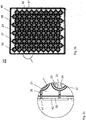
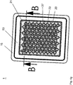
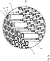
- a planar rectangular support 20 (referred to in this application as a support structure) provided, which is formed of a plastic, for example, punched or injection molded, and having a plurality of openings 22 for receiving the glass vials 2 (see. Fig. 2c ).
- the openings 22 are arranged in a regular two-dimensional arrangement, in the illustrated embodiment in a matrix arrangement of rows and columns extending at right angles, which are arranged at equal distances from each other and regularly offset from each other in a recurring arrangement.
- the openings 22 are of cylindrical side walls 37 (see. Fig. 2b ) are surrounded on the upper side of the carrier 20, which are preferably formed circumferentially, but can also be designed as only comparatively short side wall portions to limit an associated opening 22 only partially. In any case, a collision of containers received in immediately adjacent openings 22 is prevented by the side walls 37.
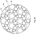
- the Fig. 2c shows a greatly enlarged section of the Fig. 2b ,
- four elastic retaining tongues 23 project into it, which are arranged along the edge of the openings 22 at equal angular intervals to each other and are each separated via a slot 24 from each other.
- the retaining tongues 23 are in particular formed integrally with the plate 21 of the carrier 20, which can be realized in a simple manner by conventional 1K or 2K injection molding processes.
- the holding tongues 23 are initially pivoted away elastically, in order to conform to the narrowed neck portion 5 of the container 2 after an elastic pivoting back (cf. Fig. 3c ) or to support the containers in this area, as described below.
- Fig. 2c can withdraw from the upright and circumferentially formed side wall 35 of the carrier 20 from a plurality of projections 40 from the side, which are interrupted in a predetermined geometry through slots 41, but this is not absolutely necessary.
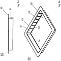
- the Figures 2d and 2e show a holding frame for holding such a carrier 20 to form a holding structure according to a first embodiment of the present invention.
- the frame 50 is formed by a circumferential side wall 51, which merges into a flange-like, circumferentially formed upper edge 53.
- the frame is formed open on the top and bottom, so that the side wall 51 surrounds an opening 55.
- a plurality of ribs 52 are formed, which on the one hand can serve to stiffen the frame 50, on the other hand, because of their geometric arrangement, can also serve to uniquely define the position of a carrier 20 in such a frame 50 as described above ,
- the ribs 52 need not extend over the entire height of the side wall 51, so that together they form a plurality of support points for supporting the carrier.
- a projection 54 is formed, which is formed circumferentially in this example (which is not absolutely necessary) and protrudes inwardly into the opening 55.
- the frame 50 and the carrier 20 are according to the invention coordinated so that the carrier 20 can be received in the frame 50 and the projections 40 on the side wall 35 of the carrier (see. Fig. 2c ) in a first orientation of the carrier lie directly on the formed by the upper ends of the ribs 52 holding points.
- the ribs 52 on the side wall 51 of the frame 50 engage in the slots 41 between the protrusions of the carrier 20, so that the carrier 20 can slide down along the side wall 51, until finally the projections 40 rest on the lower edge 54 of the frame 20.
- the holding tongues 23 are designed according to the invention in order to keep the containers axially secured to the carrier 20 in both orientations of the carrier 20 (ie in both positions of the containers, ie upright or upside down).
- This is exemplified in a comparison Figures 3h and 3i shown.
- the containers are upside down, ie with their widened upper edge 6 facing downward, so inserted into the openings of the plate 21 of the carrier 20, that the upper edge protrudes beyond the plate 21 and the container in the region of their narrowed neck portion on the retaining tongues of the plate 21 are held as described above with reference to Fig. 2c described.
- the carrier 20 is inserted from above into the holding frame 53, that the projections 40 on the side wall of the carrier 20 (see. Fig. 2c ) on the projection 54 at the lower edge of the side wall 51 of the frame 50 (see. Fig. 2e ) rest.
- the lower ends of the container 2 ie in the Fig. 3h the filling openings of the carpules 2 are arranged at a predetermined distance from the upper side of the upper edge 53 of the holding frame 50.
- the container 2 the upper edges of the container 2 (in the Fig. 3i the further openings at the upper edge 6 of the carpules 2) are arranged at the same predetermined distance from the upper side of the upper edge 53 of the holding frame 50.
- the support structure formed jointly by the carrier 20 and the frame 50 is tuned to the length of the containers 2 so that the upper ends 6 of the containers 2 in the position according to Fig. 3i are arranged at the same distance from the top of the upper edge 53 of the holding frame 50 as the lower ends 8 of the container 2 in the position according to the Fig. 3h ,
- both ends of the containers 2 are freely accessible for treatment or processing of the containers 2, since in both positions the ends of the containers 2 extend over the upper or lower edge of the holding structure formed by the carrier 20 and the frame 50 stick out.
- the Fig. 3h shows the frame 50 with the support 20 supported therein and the containers 2 held by these in the second position in the sense of claim 1.
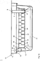
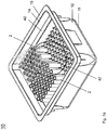
- a transport and packaging container 10 For transport and packaging of the above-described support structure with the containers received therein serves a transport and packaging container 10, as shown schematically in the Fig. 9a is shown for a one-piece carrier, as Retaining structure acts, but is not formed in two parts according to the present invention.
- the transport and packaging container 10 is substantially box-shaped or trough-shaped and has a bottom 11, a vertically projecting from this, circumferentially formed side wall 12, one of this substantially rectangular projecting step 13, a circumferentially formed upper side wall 14 and an upper Edge 15, which is formed like a flange
- the corners 16 of the transport and packaging container 10 are suitably rounded.
- the upper side wall 14 may be inclined at a slight angle of inclination to the normal to the floor 11 to facilitate the insertion of the support structure formed by a flat support 20.
- a transport and packaging container 10 is preferably made of a plastic, in particular by plastic injection molding technology, and is preferably formed of a clear, transparent plastic to provide a visual visual inspection of the carrier 20, which is received in the transport and packaging container 10, and the container 2 held by the carrier 20.
- the carrier and the transport and packaging container 10 have mutually cooperating positioning structures, which cooperate in particular form-fitting manner.
- positioning structures in the form of projections or recesses or recesses may be formed, which cooperate positively with correspondingly formed recesses or depressions or projections of the carrier 20 in order to precisely position the carrier 20 in the transport and packaging container 10.
- a plurality of peg-like projections may be formed, which engage in correspondingly formed centering openings 27 in the carrier 20.
- the step 13 of the transport and packaging container 10 is formed as a circumferential, planar support surface, on which the carrier 20 rests directly.
- further support surfaces 18 or support elements may be formed on the side walls 12 of the transport and packaging container 10.
- the lower end of the transport and packaging container 10 may also be open in the manner of the upper end, in particular with a flange-like lower edge in the Be provided type of the upper edge 15 so that the bottoms of the vials 2 are freely accessible from the bottom of the transport and packaging container 10 ago, for example, for processing steps in a sterile tunnel or in a freeze-drying cabinet, as explained in more detail below.
- FIGS. 3a to 3g The inclusion of a support structure which is in two parts and a holding frame 50 and a carrier 20 according to the FIGS. 2a to 2g is formed in a transport and packaging container 10, as described above, is in the FIGS. 3a to 3g shown.
- the support structure can be supported directly on the bottom 11 of the transport and packaging container 10 or can be supported on support surfaces of the transport and packaging container 10.
- the upper edge 53 of the support frame 50 may be supported on the upper ends of protrusions provided on the side wall 12 or on the floor 11 of the transport and packaging container 10. In this way, more than two height levels of the ends of the container 2 held on the carrier 20 can be realized according to the invention.
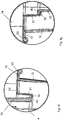
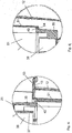
- the Fig. 3f shows the one in the Fig. 3c circled partial section in a greatly enlarged representation, in a position in which the carrier 20 is inserted into the frame 50 so that the carpules 2 are suspended upright in the openings 22 of the plate 21 of the carrier 20.
- the Fig. 3g shows, however, the in the Fig. 3e circled partial section in a greatly enlarged view, in a position in which the carrier 20 is inserted into the frame 50 so that the carpules 2 are inserted upside down into the openings 22 of the plate 21 of the carrier 20 and the carpules 2 on the Top of the carrier 20 are arranged.
- FIGS. 4a to 4j show the inclusion of a support structure according to another embodiment in a transport and packaging container 10, as described above and claimed in claim 2.
- the front ends of the containers designed as carpules 2 can be inserted into the openings of the plate 21 of the carrier 20 such that the widened upper edge protrudes slightly beyond the plate 21 and that the holding tongues support the carpules 2 respectively in the area of the narrowed neck portion or hold.
- the front ends extend the carpules through the trained by the cylindrical side walls 37 shots.
- the side walls 37 are provided with a slot 37a and can thus be widened slightly, approximately to lead or clamp the front ends of the carpules.
- the side walls 37 prevent a collision of immediately adjacent to each other on the carrier 20 held carpules. 2
- the Fig. 4i shows the one in the Fig. 4f circled portion in a greatly enlarged view, in a position in which the carrier 20 is inserted into the frame 50 so that the carpules 2 are suspended upright in the openings 22 of the plate 21 of the carrier 20, which is the second position in Meaning of claim 2 corresponds.
- the lower ends of the carpules 2 are inserted into the receptacles formed by the side walls 37 so that they rest directly on the plate 21 of the carrier 20, which corresponds to the first position in the sense of claim 2.
- the side walls 37 can also slightly clamp the lower ends of the carpules 2.
- the Fig. 4j shows the in the Fig. 4h circled partial section in a greatly enlarged representation, in a position in which the carrier 20 is inserted into the frame 50 so that the lower ends of the carpules 2 are inserted into the receptacles formed by the side walls 37 and the upper ends of the carpules 2 with the provided there widened edges 6 are also directed to the upper insertion opening of the transport and packaging container 10, which corresponds to the first position in the sense of claim 2. Because the front ends of the carpules 2 are not inserted into the openings of the plate 21 of the carrier 20 in this position, the distance of the upper edge 6 of the carpules 2 in the position according to the Fig.
- This height difference essentially corresponds to the axial length of the narrowed neck section at the upper edge of the carpules 2 and is thus negligible compared to the total length of the carpules 2 in the sense of the present application.
- the Fig. 4k shows the transport and packaging container described above in an exploded perspective view.
- the Fig. 4l shows a schematic representation of a method for the simultaneous treatment or processing of a plurality of containers according to the present invention.
- a holding structure is shown in the left and right part of the image, wherein the container 2 in the left part of the image with opposite orientation to the carrier 20th are held as in the right part of the picture.
- the support structures are conveyed by means of a conveyor 113, for example by means of conveyor rollers or conveyor chains, in the direction of the arrow, ie in the Fig. 4l left to right.
- the conveyor 113 may, for example, act on the upper edge 53 of the holding frame 50.
- the associated transport and packaging container not shown.
- the treatment or processing of the containers may be made optionally without such a shipping and packaging container or while the holding structure is received in the shipping and packaging container. If the bottom of the transport and packaging container is then formed closed, such as in the Fig. 9a illustrated, the treatment or processing of the container can then take place only from the upper insertion opening of the transport and packaging container ago.
- the containers 2 held on the holding structure are automatically conveyed past processing stations 111, 112 for treatment or processing, which can be arranged above and / or below the conveyor 113.
- the process stations 111, 112 need regardless of whether the container 2 on the support structure in the first position (that is, for example, upright) or in the second position (that is, for example, upside down) are kept not adjusted in height, so the containers 2 can be handled or processed because the upper and lower ends are at the same height level in both positions (orientations) except for the unavoidable tolerances as stated above.
- the Fig. 5a shows a further embodiment of a support for a support structure according to the present invention, in which the retaining tongues 23 are formed as elastic retaining tongues arcuately projecting from the top of the plate 21 of the carrier and project radially inwardly into the associated openings of the plate 21 of the carrier. It can be seen in particular that in the rest position or holding position, the carpules are preferably held so that a radial clearance between the front ends of the retaining tabs 23 and the narrowed neck portion 5 of the carpules is present and thus in the position according to the left part of the image Fig.
- the bottom of the widened upper edge 6 of the carpules rest on the front ends of the retaining tongues 23 or that in the position according to the right part of the image Fig. 5a the transition region between the narrowed neck portion 5 and the cylindrical side wall 4 of the carpules on the The back of the elastic retaining tongues 23 rest loosely.
- the dashed line indicates it in the Fig. 5a the same height level of the upper edge 6 of the carpules and the lower end 8 of the cartridges when they are held on the plate 21.
- the Fig. 5b shows in a partial section the retaining tongue of a support of a support structure according to another embodiment.
- the elastic retaining tongues 23 are like a flag and formed with a radially inwardly projecting retaining lug.
- the elastic retaining tongues 23 are connected to the plate 21 via a resilient base 23a protruding perpendicularly from the upper side of the plate 21 of the carrier.
- the base 23a merges into a radially inwardly curved portion 23b, which eventually merges into the retaining lug 23c, on which the widened edge 6 (see FIG. Fig. 1 ) the container rests.
- the retaining lug 23c protrudes into the opening of the plate 21 of the carrier.
- the retaining lug 23 c merges into an obliquely upwardly extending insertion bevel 23 f, which connects to the upper end of the retaining tongue 23.
- a recess 23d is formed, in which the upper edge 6 is secured axially in both directions (thus suitable for an upright orientation or an orientation upside down) and received with radial play. Due to the insertion bevel 23f on the upper side of the retaining tongue 23 and the downwardly opened, curved portion 23b of the retaining tongue 23, the containers can optionally be introduced from above or from below into the openings of the plate 21 of the carrier and withdrawn from this again.
- the bottoms or lower ends of the containers When the containers are introduced from above into the openings of the carrier, the bottoms or lower ends of the containers initially come into contact with the insertion bevels 23f of the holding tongues 23. Upon further insertion of the containers, the lower end or bottom of the containers slides along the insertion bevels 23f downward and spreads the retaining tongues 23 increasingly elastically apart or folds or pivots them back. Upon further insertion of the container, finally, the cylindrical side wall 4 of the container into abutment with the retaining lugs 23e and slides along this, until finally the bottom of the widened edge 6 of the container loosely rests on the retaining lugs 23c of the retaining tongues 23. The containers can then be removed either upwards with reversed movement of the holding tongues 23 or downwards with elastic bending of the holding tongues 23 from the openings of the plate 21 of the carrier.
- the upper end of the container Upon insertion of the containers from below into the openings of the carrier, the upper end of the container first comes into abutment with the curved portion 23b of the retaining tabs 23. Upon further insertion of the container, the upper end of the container slides along the curved portions 23b and spreads the retaining tongues 23 increasingly elastically apart or folds or pivots them back until finally the retaining lugs 23 c are reached. Upon further pushing up the container, the underside of the widened edge 6 of the container slides over the retaining lugs 23c of the retaining tongues 23 and finally lies loosely on the retaining lugs 23c of the retaining tongues 23. The containers can then be removed either downwards with reversed movement of the retaining tongues 140 or upwards with elastic bending of the retaining tongues 23 from the openings of the plate 21 of the carrier.
- the widened upper edge portion 6 (rolled edge) of the container is clamp-like and positively embraced, with a sufficient radial clearance, as described above, is ensured, as through the air gap in the radial direction in the Fig. 5b indicated.
- a sufficient axial clearance can be ensured, as through the air gap in the axial direction in the Fig. 5b indicated.
- the Figures 6a to 6h show further variants for mounting the container to a carrier, which may be provided in addition or as an alternative to the holders described above.
- the Fig. 6a shows a trained as a half-shell side wall 37 which protrudes from the underside of the plate 21 of the carrier and at its lower end has a radially inwardly projecting projection 37b, in which a recess is formed.
- This projection 37b can be used as a stop for fixing the axial position of the container 2 to the carrier, as in the Fig. 6b shown, in which the bottom of the widened upper edge 6 of the container 2 loosely and preferably rests with radial play on the front ends 23g of the retaining tongues 23a.
- the Fig. 6a shows a trained as a half-shell side wall 37 which protrudes from the underside of the plate 21 of the carrier and at its lower end has a radially inwardly projecting projection 37b, in which a recess is formed.
- FIGS. 6d and 6e show further side views of this support structure.
- the Fig. 6f shows finally another embodiment in which the side wall 37 is shorter than the side wall of the container 2 is formed and thus the entire lower end of the container 2 is freely accessible from the underside of the carrier ago.
- the lower edge of the carpule is supported on the projection 37b, but the filling opening at the lower end of the carpule freely accessible, for example, for a filling of the carpule.
- the Figures 6g and 6h show this holding structure in a plan view and a bottom view.
- the Fig. 6i shows by way of example the measurement of the filling level or the filling quantity of a container designed as a carpule by means of a laser 100. It is assumed that the carpule is filled via the filling opening at the upper edge 6 by means of an injection needle 110.
- the hatched area 9a indicates the already filled part of the carpule, while above this area there is an unfilled area 9b, for example filled with air or an inert gas.
- the laser beam 101 of the laser 100 radiates through the narrowed neck portion 5 of the carpule.
- the laser beam 101 is detected on the opposite side of the carpule by means of an optical sensor 102.
- the carpule is also filled in the area of the laser beam 101, a lateral offset or a deflection of the laser beam 101, which can be detected with the sensor 102, occurs due to the other optical conditions along the beam path. Since the laser beam 101 can be collimated to a relatively small beam diameter, the actual filling quantity of the carpule can thus be detected precisely and, for example, when a predetermined filling level is reached, processing or processing of the carpule, for example a filling process, can be aborted.
- FIGS. 7a to 7f show a support structure, according to another embodiment for a better understanding of the present invention.
- cylindrical or hollow cylindrical pins 42 protrude substantially perpendicularly from the plate of the carrier 20 to prevent contact of containers held immediately adjacent to the carrier 20.
- the carrier 20 is substantially open and is spanned by crossing retaining webs 43, which form a net-like bottom of the carrier, on which the pins 42 are arranged.
- retaining webs 43 which form a net-like bottom of the carrier, on which the pins 42 are arranged.
- Each six retaining pins 42 form a receptacle in which the lower or upper end of the container is received. It can between the retaining pin 42 and the side wall 4 of Container a radial clearance be present. Or the retaining pins 42 may tangentially rest on the side wall 4 of the container and possibly even slightly clamp them.
- the intersecting retaining webs 43 support the respective ends of the container.
- FIG. 7d How to get the Fig. 7d and the greatly enlarged partial view according to the Fig. 7e can take the containers 2 (shown in the figures as carpules) in the receptacles formed by the pins 42, be inserted upright or upside down. According to the Fig. 7d a carrier formed in this way is received directly in the transport and packaging container 10.
- an additional support frame (not shown) is additionally provided in which the support is in turn received, as described above with reference to FIG Figures 2 described to form a two-part support structure.
- the Fig. 7f shows a transport and packaging container 10 according to such another embodiment in an exploded perspective view.
- a recessed portion may be formed in order to form a receptacle for a narrowed neck section 5 of the containers to be held (cf. Fig. 1 ) to counteract tilting of the container held on the carrier.
- this corresponds substantially to the axial length of the narrowed neck portion 5 of the container to be held and thus is usually negligible compared to the total length of the container.
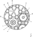
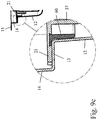
- the Fig. 8a shows in a plan view a holding structure according to another embodiment of the present invention.
- cylindrical or hollow cylindrical pin 42 is substantially perpendicular to prevent contact of immediately adjacent containers, which are held on the carrier 20.
- the pins 42 are connected to each other via webs 47, which are intended to serve to stiffen the bottom 21.
- a total of six pins 42 are arranged at equal angular intervals to each other around the respective openings 22 of the carrier 20 to form a receptacle in which a container is to be received.
- the bottom 21 of the carrier 20 is, except for the openings 22, formed closed and is preferred made of a plastic.
- an elastic material for example a rubber or flexible plastic
- a sealing element can also be placed on the bottom 21 of the carrier 20 as a separate sealing ring around the openings 22.
- the carrier 20 is formed trough-shaped, with a comparatively wide edge 40 which is connected via slightly inwardly inclined side walls 35 to the bottom 21.
- ribs 46 are formed, which serve as spacers, when a plurality of such carriers 20 are stored stacked one above the other.
- the Fig. 8b shows the in the Fig. 8a circled section in a greatly enlarged view.
- the filling and closing of pre-sterilized cartridges is of particular interest because it must be ensured that the drug stored in the carpule retains its properties for years.
- the carpule is evacuated according to the invention and then a plug inserted into the rear end of the carpule in order to close this.
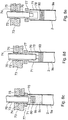
- the plug 80 is inserted into a cylinder 71 by a vacuum gripper 70 in a compressed state and kept compressed in the cylinder 71.
- the outer diameter of the cylinder 71 is smaller than the inner diameter of the carpule 2. Further, the inner diameter of the cylinder 71 is smaller than the outer diameter of the plug 80 when it is not compressed.
- the vacuum gripper 70 can be adjusted axially together with the cylinder 71, but also be axially displaced relative to the cylinder 71.
- a liquid 9a is filled in the carpule 2, of which in the FIGS. 8c to 8e only the rear end is shown.
- the internal volume 9b of the carpule 2 is not filled.
- an annular sealing member 77 is placed to seal the rear end of the carpule 2 against the environment.
- the cylinder 71 may be inserted with the vacuum gripper 70 because the outer diameter of the cylinder 71 is smaller than the diameter of the opening.
- a plunger 73 which is sealed by a sealing ring 74 against the cylinder 71.
- Cylinder 71 and vacuum gripper 70 can be adjusted axially relative to the plunger 73.
- the plunger 73 serves as a contact surface which bears against the sealing element 77 and can pressurize it to seal the interior volume of the carpule from the environment.
- a radial suction channel 75 is formed, via which by means of a suction device (not shown), air or gas can be sucked out of the annular gap 76 between the cylinder 71 and the carpule 2.
- the sealing member 77 may be made of an elastic rubber material and placed on the rear edge of the carpule 2 as a separate element.
- the sealing element may also be the bottom 21 of a carrier 20 (cf. Fig. 8a ) or act around the respective opening 22 around in the bottom 21 of the carrier 20 arranged or applied sealing element.
- a sorting pot (not shown) supplies the vacuum gripper 70 with plugs 80 which it is intended to press in the end of the carpule.
- the vacuum gripper 70 presses the plug 80 into the cylinder 71, the plug 80 is compressed as in the Fig. 8c shown.
- the vacuum gripper 70 is placed with the cylinder 71 and the plunger 73 on the rear edge of the carpule 2, wherein the sealing member 77 is clamped between the plunger 73 and the rear edge of the carpule 2 to the non-liquid-filled internal volume 9b and seal the annular gap 76 between the cylinder 71 and the carpule 2 against the environment.
- the vacuum gripper 70 is moved relative to the cylinder 71 axially toward the liquid level 9c.
- the plug 80 is first pressed out of the cylinder 71, so that this is relaxed and sealing against the inner wall of the carpule 2.
- the vacuum gripper 70 is further displaced axially relative to the cylinder 71 toward the liquid level 9c until the plug 80 rests on the liquid level 9c, as in FIG Fig. 8d shown.
- the seal assembly can be dissolved again and the vacuum gripper 70 and the cylinder 71 can again be axially moved out of the rear end of the carpule 2, as in Fig. 8d shown.
- the vacuum gripper 70 is further displaced axially relative to the cylinder 71, as in the Fig. 8e and the vacuum gripper 70, together with the cylinder 71, is axially moved out of the rear end of the carpule 2, so that a new closing operation can begin.
- a visual check can make sure that the plugs are actually present. Furthermore, the positions of the carpule, the stopper and / or the vacuum gripper can be determined and adjusted appropriately.
- a towing track can place caps on the stoppered cartridges.
- the closure caps may in particular be metal lids which are crimped onto the edge of the carpules. These caps can also perform here a sorting pot.
- a filling of containers, in particular of cartridges, under vacuum, with which the formation of bubbles can be prevented, is usually carried out with rotary piston pumps.
- the art of processing viscous liquids under vacuum is to find a balance of the various parameters. A too deep vacuum can cause the product to boil in conventional processes. The conventional setting of the plug in turn there is a risk that product is sucked past the stopper from the carpule. However, if the vacuum is too low, air bubbles or bubbles will not dissolve.
- the above-mentioned closing operation can in particular also be carried out so that the containers, in particular carpules, are fed in a carrier as described above in a predetermined geometric arrangement of a closing station, wherein an open end of the containers as close as possible to the bottom of the Carrier is arranged.
- the open end of a container may be supported directly on the bottom of the carrier or the open end, for example the neck of a container, may extend through the openings in the bottom of the carrier to the other side of the carrier.
- the bottom of the carrier can act directly as a counter element for the plunger of the Verschschier station.
- the containers are held on the carrier so that their open ends are aligned with the openings in the bottom of the carrier.
- the plunger of the sealing station approaches the open end of the container as described above, and the closing operation is carried out as described above while the containers are held on the carrier.
- the containers may also be held to the support structures by any other positive or non-positive connection.
- the holding force exerted on the containers by the holding means is sufficient to reliably hold the containers to the holding structure.
- the holding force exerted is greater than the weight of the container, possibly with content and plugs. This ensures a reliable mounting of the container to the support structure.
- the containers can be adjusted in the openings or receptacles of the support structure without much effort, in particular axially advanced or rotated.
- the support structure or the support in the context of the present invention also be formed of a thermoplastic, thermosetting or elastomeric plastic, wherein at least portions of the support structure and the carrier are provided with a Reibreduroisden coating to the insertion and removal of the container to facilitate.
Description
Die vorliegende Erfindung betrifft die gleichzeitige Halterung einer Mehrzahl von Behältern zur Aufbewahrung von Substanzen für medizinische, pharmazeutische oder kosmetische Anwendungen, insbesondere von Fläschchen (Vials), Spritzen (syringe) und Doppelkammer-Spritzen (dual-chamber syringe), Karpulen (cartridges), Doppelkammer-Karpulen (dual chamber cartridges) oder Vartridges, in einfacher und zuverlässiger Weise sowie dergestalt, dass diese, während diese in einer hierfür vorgesehenen Haltestruktur gehalten werden, in Abfüll- oder Bearbeitungsanlagen prozessiert oder weiter verarbeitet werden können, insbesondere in einem Steriltunnel, einer Abfüllanlage für flüssige medizinische oder pharmazeutische Anwendungen oder einem Gefriertrockenschrank hierfür. Ferner betrifft die vorliegende Erfindung einen Transport- und/oder Verpackungsbehälter mit zumindest einer solchen Haltestruktur sowie ein Verfahren zur Behandlung oder Verarbeitung solcher Behälter.The present invention relates to the simultaneous mounting of a plurality of containers for storing substances for medical, pharmaceutical or cosmetic applications, in particular vials, syringes and dual-chamber syringe, cartridges, Dual chamber cartridges or vartridges, in a simple and reliable manner, and in such a way that, while they are held in a holding structure provided for this, they can be processed or further processed in filling or processing plants, in particular in a sterile tunnel Filling plant for liquid medical or pharmaceutical applications or a freeze-drying cabinet therefor. Furthermore, the present invention relates to a transport and / or packaging container with at least one such support structure and a method for the treatment or processing of such containers.
Als Behälter zur Aufbewahrung und Lagerung von medizinischen, pharmazeutischen oder kosmetischen Präparaten mit Verabreichung in flüssiger Form, insbesondere in vordosierten Mengen, werden in großem Umfang Medikamentenbehälter, wie beispielsweise Fläschchen, Ampullen oder Karpulen, eingesetzt. Diese weisen generell eine zylindrische Form auf, können aus Kunststoffen oder aus Glas hergestellt werden und sind kostengünstig in großen Mengen erhältlich. Für eine möglichst wirtschaftliche Befüllung der Behälter unter sterilen Bedingungen werden in zunehmendem Maße Konzepte eingesetzt, bei denen die Behälter gleich beim Hersteller der Behälter in Transport- und Verpackungsbehälter steril verpackt werden, die bei einem Pharmaunternehmen dann unter sterilen Bedingungen, insbesondere in einem sog. Steriltunnel, ausgepackt und dann weiter verarbeitet werden.As a container for storage and storage of medical, pharmaceutical or cosmetic preparations with administration in liquid form, in particular in pre-dosed amounts, medicine containers, such as vials, ampoules or cartridges, are used on a large scale. These generally have a cylindrical shape, can be made of plastics or glass and are available in large quantities at low cost. For the most economical filling of the container under sterile conditions concepts are increasingly used in which the containers are packaged sterile sterile at the manufacturer of containers in transport and packaging containers, which then at a pharmaceutical company under sterile conditions, especially in a so-called. Sterile tunnel , unpacked and then processed further.
Zu diesem Zweck sind aus dem Stand der Technik div. Transport- und Verpackungsbehälter bekannt, in denen gleichzeitig eine Mehrzahl von Medikamentenbehältern in einer regelmäßigen Anordnung angeordnet sind. Dies hat Vorteile bei der automatisierten Weiterverarbeitung der Behälter, da die Behälter an kontrollierten Positionen und in vorgegebener Anordnung an Bearbeitungsstationen übergeben werden können, beispielsweise an Prozessautomaten, Roboter oder dergleichen. Hierzu werden Haltestrukturen eingesetzt, in welchen gleichzeitig eine Mehrzahl von Behältern in einer vorbestimmten regelmäßigen Anordnung gehalten werden können. Zur Übergabe an eine Bearbeitungsstation braucht einfach nur der Transport- und Verpackungsbehälter geeignet positioniert und geöffnet zu werden. Die nachgeordnete Bearbeitungsstation weiß dann, in welcher Position und Anordnung die weiter zu verarbeitenden Behälter angeordnet sind.For this purpose, div. Transport and packaging containers are known from the prior art, in which a plurality of drug containers are arranged in a regular arrangement at the same time. This has advantages in the automated further processing of the containers, since the containers can be transferred to processing stations in controlled positions and in a predetermined arrangement, for example to process machines, robots or the like. For this purpose, holding structures are used, in which at the same time a plurality of containers can be held in a predetermined regular arrangement. To transfer to a processing station just needs the transport and packaging container properly positioned and open to become. The downstream processing station then knows in which position and arrangement the containers to be further processed are arranged.
Ein solcher Transport- und Verpackungsbehälter und ein entsprechendes Verpackungskonzept sind beispielsweise in der
Ein weiterer vergleichbarer Transport- und Verpackungsbehälter und Haltestrukturen sind in der
Ein weiterer vergleichbarer Transport- und Verpackungsbehälter und eine Haltestrukturen sind in der
Aufgabe der vorliegenden Erfindung ist es, eine Haltestruktur zum gleichzeitigen Halten einer Mehrzahl von Behältern für medizinische, pharmazeutische oder kosmetische Anwendungen, dahingehend weiterzubilden, dass die Behälter in flexibler Anpassung an die Bedingungen bei deren Behandlung oder Verarbeitung einfach und zuverlässig gehalten sowie kostengünstig steril verpackt, wieder entpackt und weiterverarbeitet werden können. Gemäß einem weiteren Gesichtspunkt der vorliegenden Erfindung sollen ferner ein entsprechender Transport- und Verpackungsbehälter mit zumindest einer solchen Haltestruktur sowie ein entsprechendes Verfahren zur Behandlung oder Verarbeitung von Behältern bereitgestellt werden.Object of the present invention is to develop a holding structure for simultaneously holding a plurality of containers for medical, pharmaceutical or cosmetic applications, to the effect that the container in flexible adaptation to the conditions during their treatment or processing kept simple and reliable and cost-sterile packaging, can be unpacked and processed further. According to a further aspect of the present invention, a corresponding transport and packaging container with at least one such holding structure and a corresponding method for treating or processing containers should also be provided.
Diese Aufgaben werden gemäß der vorliegenden Erfindung durch eine Haltestruktur mit den Merkmalen nach Anspruch 1 bzw. Anspruch 2, durch einen Transport- und Verpackungsbehälter nach Anspruch 9 sowie durch ein Verfahren nach Anspruch 10 bzw. 11 gelöst. Weitere vorteilhafte Ausführungsformen sind Gegenstand der rückbezogenen Unteransprüche.These objects are achieved according to the present invention by a support structure with the features of
Somit wird eine Haltestruktur zum gleichzeitigen Halten einer Mehrzahl von Behältern einer vorbestimmten Länge bereitgestellt, die zur Aufbewahrung von Substanzen für medizinische, pharmazeutische oder kosmetische Anwendungen dienen oder diese enthalten, mit einem Träger, der eine Mehrzahl von Haltemitteln aufweist und ausgelegt ist, um die Behälter wahlweise in einer ersten Orientierung (beispielsweise aufrecht) oder in einer zweiten Orientierung, die entgegengesetzt zur ersten Orientierung ist (also beispielsweise kopfüber), zu halten.Thus, a holding structure is provided for simultaneously holding a plurality of containers of a predetermined length, which serve to contain or contain substances for medical, pharmaceutical or cosmetic applications, with a carrier having a plurality of holding means and adapted to the containers optionally in a first orientation (eg upright) or in a second orientation opposite to the first orientation (eg upside down).
Gemäß einer ersten Ausführungsform ist die Haltestruktur erfindungsgemäß zweiteilig ausgebildet und umfasst den Träger und einen Rahmen, an welchem der Träger in einer ersten vorbestimmten Orientierung oder in einer zweiten vorbestimmten Orientierung, die entgegengesetzt zu der ersten vorbestimmten Orientierung ist, abstützbar ist, wobei der Träger so auf die axiale Länge der Behälter abgestimmt, dass die oberen Enden der Behälter in einer ersten Stellung, in welcher die Behälter in der ersten Orientierung an dem Träger gehalten sind und der Träger in der ersten vorbestimmten Orientierung an dem Rahmen abgestützt ist, unter dem gleichen Abstand zum oberen Rand des zur Abstützung des Trägers dienenden Rahmens angeordnet sind wie die unteren Enden der Behälter in einer zweiten Stellung, in welcher die Behälter in der zweiten Orientierung an dem Träger gehalten sind und der Träger in der zweiten vorbestimmten Orientierung an dem Rahmen abgestützt ist, und die oberen Enden und/oder unteren Enden der Behälter, während diese an dem Träger gehalten sind, für eine Weiterverarbeitung der Behälter zugänglich sind.According to a first embodiment, the support structure according to the invention is formed in two parts and comprises the support and a frame, on which the support is supportable in a first predetermined orientation or in a second predetermined orientation, which is opposite to the first predetermined orientation, the support being so matched to the axial length of the containers, that the upper ends of the container in a first position, in which the containers are held in the first orientation on the carrier and the carrier is supported in the first predetermined orientation on the frame, at the same distance are arranged to the upper edge of the frame for supporting the support as the lower ends of the container in a second position in which the containers are held in the second orientation on the carrier and the carrier is supported in the second predetermined orientation on the frame, and the upper ones Ends and / or lower ends of the containers, while they are held on the carrier, are accessible for further processing of the containers.
Gemäß einer alternativen zweiten Ausführungsform ist die Haltestruktur erfindungsgemäß zweiteilig ausgebildet und umfasst den Träger und einen Rahmen, an welchem der Träger in einer ersten Orientierung oder in einer zweiten Orientierung, die entgegengesetzt zu der ersten Orientierung ist, abstützbar ist, wobei der Träger so auf die Länge der Behälter abgestimmt ist, dass die oberen Enden der Behälter in einer ersten Stellung, in welcher die Behälter in einer vorbestimmten Orientierung an dem Träger gehalten sind und der Träger in der ersten Orientierung an dem Rahmen abgestützt ist, unter dem gleichen Abstand zum oberen Rand des zur Abstützung des Trägers dienenden Rahmens angeordnet sind wie die oberen Enden der Behälter in einer zweiten Stellung, in welcher die Behälter in der gleichen vorbestimmten Orientierung an dem Träger gehalten sind und der Träger in der zweiten Orientierung an dem Rahmen abgestützt ist, wobei die oberen Enden der Behälter, während der Träger in der ersten Orientierung an dem Rahmen abgestützt ist und die Behälter in der vorbestimmten Orientierung an dem Träger gehalten sind, für eine Weiterverarbeitung der Behälter zugänglich sind, und die oberen Enden und/oder unteren Enden der Behälter, während der Träger in der zweiten Orientierung an dem Rahmen abgestützt ist und die Behälter in der vorbestimmten Orientierung an dem Träger gehalten sind, für eine Weiterverarbeitung der Behälter zugänglich sindAccording to an alternative second embodiment, the support structure according to the invention is formed in two parts and comprises the support and a frame on which the support is supportable in a first orientation or in a second orientation, which is opposite to the first orientation, the support so on Length of the container is matched, that the upper ends of the container in a first position in which the containers are held in a predetermined orientation on the carrier and the carrier is supported in the first orientation on the frame, at the same distance from the upper edge the support supporting frame are arranged as the upper ends of the containers in a second position in which the containers are held in the same predetermined orientation on the carrier and the carrier is supported in the second orientation on the frame, wherein the upper Ends the container while the Carrier is supported in the first orientation on the frame and the containers are held in the predetermined orientation on the carrier, are accessible for further processing of the container, and the upper ends and / or lower ends of the container, while the carrier in the second orientation is supported on the frame and the containers are held in the predetermined orientation on the carrier, are accessible for further processing of the container
Somit brauchen Prozessstationen, in denen die Behälter weiter behandelt oder verarbeitet werden, unabhängig davon, ob die Behälter an der Haltestruktur in der ersten Orientierung (also beispielsweise aufrecht stehend) oder in der zweiten Orientierung (also beispielsweise kopfüber) gehalten werden, in ihrer Höhe nicht verstellt werden, um die Behälter zu behandeln oder zu verarbeiten. Denn die oberen und unteren Enden der Behälter befinden sich in beiden Stellungen auf dem gleichen Höhenniveau. Dies erleichtert die Behandlung und Verarbeitung der Behälter erfindungsgemäß erheblich, da der Aufwand hinsichtlich Justierung, Steuerung und Automatisierung erheblich vereinfacht werden kann.Thus, regardless of whether the containers are held to the support structure in the first orientation (ie upright, for example) or in the second orientation (eg, upside down), process stations in which the containers are further processed or processed need not have their height be adjusted to treat or process the containers. Because the upper and lower ends of the container are in the same positions in both positions. This facilitates the treatment and processing of the container according to the invention considerably, since the effort in terms of adjustment, control and automation can be considerably simplified.
Mit dem Begriff "unter dem gleichen Abstand" sollen im Sinne der vorliegenden Anmeldung natürlich zunächst unvermeidliche Längentoleranzen der Behälter mit berücksichtigt sein. Anderseits sollen gemäß weiteren Ausführungsformen auch Toleranzen mit berücksichtigt sein, die durch eine unterschiedliche Halterung der oberen und unteren Enden der Behälter an dem Träger bedingt sind und bevorzugt maximal von der Größenordnung der axialen Länge eines verengten oberen Hals- oder Nackenabschnitts der zu haltenden Behälter sind oder die diese axiale Länge, im Vergleich zur Gesamtlänge der zu haltenden Behälter, allenfalls geringfügig überschreiten, beispielsweise um maximal 20%, bevorzugter um maximal 10% der axialen Länge des verengten oberen Hals- oder Nackenabschnitts.The term "at the same distance" should, of course, be taken into account for the purposes of the present application initially unavoidable length tolerances of the container. On the other hand, tolerances should also be taken into account according to further embodiments, which are due to a different support of the upper and lower ends of the container to the support and preferably maximum of the order of the axial length of a narrowed upper neck or neck portion of the container to be held or at most slightly exceed this axial length, compared to the total length of the container to be held, for example by a maximum of 20%, more preferably by a maximum of 10% of the axial length of the narrowed upper neck or neck portion.
Gemäß einer weiteren Ausführungsform weist der Träger eine Mehrzahl von Öffnungen auf, denen jeweils bevorzugt zwei Haltemittel zugeordnet sind, um die Behälter zu halten, insbesondere mittels eines Form- oder Reibschlusses. Dabei werden die Behälter bevorzugt so von den Haltemitteln an dem Träger gehalten, dass diese sich durch die Öffnungen der Trägers hindurch erstrecken. Dabei können die oberen Enden der Behälter über einen oberen Rand des Trägers vorstehen und/oder die unteren Enden der Behälter über einen unteren Rand des Trägers vorstehen, sodass diese für eine Weiterverarbeitung der Behälter noch besser zugänglich sind.According to a further embodiment, the carrier has a plurality of openings, which are each preferably associated with two holding means to hold the containers, in particular by means of a form or frictional engagement. In this case, the containers are preferably held by the holding means on the carrier so that they extend through the openings of the carrier. The upper ends of the containers may protrude beyond an upper edge of the carrier and / or project the lower ends of the containers over a lower edge of the carrier, so that they are even more accessible for further processing of the container.
Gemäß einer weiteren Ausführungsform sind die Behälter in der ersten und zweiten Orientierung an dem Träger abgestützt oder an dem Träger axial gesichert gehalten, sodass diese auch bei einer Umkehrung der Orientierung (Wenden) des Trägers sicher an diesem gehalten sind.According to a further embodiment, the containers are supported in the first and second orientations on the carrier or held axially secured on the carrier, so that they are securely held on this even in a reversal of the orientation (turning) of the carrier.
Gemäß einer weiteren Ausführungsform sind an dem Träger, der bevorzugt flächig und insbesondere rechteckförmig ausgebildet ist, als Haltemittel an jeder Öffnung bevorzugt zwei Haltezungen vorgesehen, die am Rand einer jeweiligen Öffnung vorgesehen sind und von einer Oberseite des Trägers abragen, um den jeweiligen Behälter in der Öffnung zu halten. Dabei sind die Haltezungen so ausgelegt, dass diese beim Einführen der Behälter in die Öffnungen elastisch weggeschwenkt oder weggeklappt werden, und ferner so auf die Behälter abgestimmt, dass die Behälter mit radialem Spiel von den Haltezungen gehalten sind. Das radiale Spiel ermöglicht, dass Behälter mit unterschiedlichen radialen Toleranzen und/oder Außenabmessungen von demselben Träger zuverlässig gehalten werden können. Das radiale Spiel ist zweckmäßig so ausgelegt und auf die Außenkontur und -abmessung der Behälter abgestimmt, dass niemals gleichzeitig sämtliche Haltezungen den verengten Halsabschnitt am oberen Ende der Behälter, insbesondere Fläschchen, berühren. Gleichzeitig verhindert das radiale Spiel auch ein unerwünschtes Verspannen oder gar Aufwölben des Trägers beim Halten von Behältern mit unterschiedlichen radialen Toleranzen und/oder Außenabmessungen, was erhebliche Vorteile insbesondere bei der gleichzeitigen Prozessierung einer Mehrzahl von Behältern bietet, während diese von dem Träger gehalten sind, beispielsweise bei der Gefriertrocknung bei Prozessierung bei sehr niedrigen Temperaturen.According to a further embodiment, two retaining tongues are preferably provided on the support, which is preferably flat and in particular rectangular, as retaining means at each opening, which are provided at the edge of a respective opening and protrude from an upper side of the support to the respective container in the Hold opening. The retaining tongues are designed so that they are elastically pivoted or folded away during insertion of the container into the openings, and further tuned to the container so that the containers are held with radial play by the retaining tongues. The radial clearance allows containers with different radial tolerances and / or external dimensions to be reliably held by the same carrier. The radial clearance is expediently designed and matched to the outer contour and dimension of the container, that never at the same time all retaining tongues touch the narrowed neck portion at the upper end of the container, in particular vials. At the same time, the radial clearance also prevents unwanted distortion or even bulging of the carrier when holding containers with different radial tolerances and / or external dimensions, which offers considerable advantages in particular in the simultaneous processing of a plurality of containers while they are held by the carrier, for example during freeze-drying when processing at very low temperatures.
Die Haltezungen sind dabei gemäß einer weiteren Ausführungsform ausreichend elastisch ausgebildet oder gelagert, sodass die Behälter axial, d.h. in Richtung der Längsachse der Behälter und senkrecht zur Ebene des Trägers, von der Oberseite oder Unterseite des Trägers her in die Öffnungen oder Aufnahmen eingeschoben werden können, insbesondere unter elastischer Verformung der Haltezungen, beispielsweise unter Wegbiegen derselben. Die Bestückung des Trägers mit Behältern kann somit einfach automatisiert werden, was durch eine regelmäßige Anordnung der Öffnungen oder Aufnahmen noch weiter begünstigt wird, bevorzugt durch eine regelmäßige Anordnung der Öffnungen oder Aufnahmen in einer zweidimensionalen Matrix.The retaining tongues are in this case according to a further embodiment sufficiently elastic or mounted, so that the containers can be inserted axially, ie in the direction of the longitudinal axis of the container and perpendicular to the plane of the carrier, from the top or bottom of the carrier ago in the openings or receptacles in particular under elastic deformation of the retaining tongues, for example while bending away the same. The Equipping the carrier with containers can thus be easily automated, which is further promoted by a regular arrangement of the openings or recordings, preferably by a regular arrangement of the openings or recordings in a two-dimensional matrix.
Als bevorzugte Stelle, an der die Behälter an den Haltezungen gehalten oder abgestützt sind, hat sich die Unterseite eines verbreiterten oberen Randabschnittes der Behälter erwiesen, wie dieser insbesondere bei Fläschchen (vials) typischerweise als sog. Rollrand oder Schulter vorgesehen ist. In diesem Bereich steht eine Abstütz- oder Lagerfläche zum Halten oder Abstützen der Behälter mit einer ausreichenden Erstreckung in Radialrichtung der Öffnungen oder Aufnahmen zur Verfügung, um das vorgenannte radiale Spiel bei der Halterung der Behälter ohne Weiteres zu realisieren.As a preferred point at which the containers are held or supported on the holding tongues, the underside of a widened upper edge portion of the container has proven, as is typically provided in vials as so-called. Roll edge or shoulder. In this area, a support or bearing surface for holding or supporting the container with a sufficient extent in the radial direction of the openings or receptacles is available to realize the aforementioned radial clearance in the holder of the container readily.
Weil die Behälter in den Öffnungen oder Aufnahmen des Trägers mit sehr geringem Kraftaufwand angehoben oder bewegt werden können, diese beispielsweise gedreht werden können, können die Behälter, während diese sich in dem Träger befinden und von diesem gehalten oder zumindest gerührt werden, erfindungsgemäß ohne Weiteres bearbeitet werden. Als besonders vorteilhaft hat sich diese Art der Halterung z.B. beim Verschließen der Behälter durch Bördeln eines Metalldeckels erwiesen. Die hierzu erforderlichen Vorgänge können an dem Metalldeckel ausgeführt werden, während die Behältern in den Öffnungen oder Aufnahmen des Trägers gehalten oder zumindest geführt sind. Als besonders vorteilhaft hat sich diese Art der Halterung auch bei der Prozessierung von Behältern erwiesen, während die Behälter in der Haltestruktur gehalten bzw. aufgenommen sind. Beispielsweise können die Träger mit den darin aufgenommenen bzw. gehaltenen Behältern in einen Gefriertrockner oder Gefriertrockenschrank eingebracht werden. Aufgrund der Halterung der Behälter mit einem gewissen Spiel in den Trägem kann gewährleistet werden, dass die Böden von sämtlichen Behältern auf einer kühlenden Unterlage gleichmäßig aufliegen, beispielsweise auf einem Kühlfinger des Gefriertrockners oder Gefriertrockenschranks. Oder die Behälter können ohne größeren Kraftaufwand in den Öffnungen oder Aufnahmen des Trägers angehoben und zur Prozessierung gehandhabt werden.Because the containers can be lifted or moved in the openings or receivers of the carrier with very little effort, they can be rotated, for example, the containers while these are in the carrier and held by this or at least stirred, according to the invention readily processed become. This type of holder, for example, has proven particularly advantageous. when closing the container by crimping a metal lid proved. The operations required for this purpose can be carried out on the metal lid, while the containers are held or at least guided in the openings or receptacles of the carrier. To be particularly advantageous, this type of holder has also proven in the processing of containers, while the containers are held or received in the support structure. For example, the carriers can be introduced with the housed or held therein containers in a freeze dryer or freeze-drying cabinet. Due to the support of the container with a certain play in the carriers can be ensured that the bottoms of all containers evenly rest on a cooling surface, for example on a cold finger of the freeze dryer or freezer. Or the containers can be lifted without much effort in the openings or recordings of the wearer and handled for processing.
Gemäß einer bevorzugten Ausführungsform sind die Haltezungen als elastische Haltezungen ausgebildet, verfügen diese jedoch über eine ausreichende Elastizität, um beim Einführen der Behälter in die Öffnungen oder Aufnahmen ausreichend elastisch weggeschwenkt oder weggeklappt zu werden, um den Behältern den Weg in die Öffnungen oder Aufnahmen freizugeben. Dies lässt sich durch geeignete Dimensionierung, Materialwahl und Auslegung der Materialstärke der Haltezungen ohne Weiteres erreichen. Bevorzugt sind die Haltezungen somit aus einem Kunststoff ausgebildet.According to a preferred embodiment, the retaining tongues are formed as elastic retaining tongues, but they have sufficient elasticity to be sufficiently elastically swung or folded away during the insertion of the container into the openings or receptacles to release the containers the way into the openings or receptacles. This can easily be achieved by suitable dimensioning, choice of material and design of the material thickness of the holding tongues. Preferably, the retaining tongues are thus formed of a plastic.
Gemäß einer Ausführungsform sind die Haltezungen elastisch gegen eine Haltestellung vorgespannt, bevorzugt mittels eines elastischen Rückstellelements, beispielsweise einer Rückstellfeder oder eines Kunststoffblättchens oder elastischen Kunststoffgebildes, das mit der zugeordneten Haltezunge geeignet zusammenwirkt und auf der Oberseite des Trägers vorgesehen oder ausgebildet ist.According to one embodiment, the retaining tongues are resiliently biased against a holding position, preferably by means of an elastic return element, for example a return spring or a plastic leaflet or elastic plastic structure, which cooperates with the associated retaining tongue and is provided or formed on the upper side of the carrier.
Gemäß einer Ausführungsform sind die Haltezungen so auf die Behälter abgestimmt, dass die Behälter mit einem verbreiterten Rand, der an einem oberen Ende der Behälter ausgebildet ist, also insbesondere mit dem vorgenannten Rollrand, lose auf Oberseiten der Haltezungen aufliegen. Die Behälter können somit ohne größeren Widerstand wieder aus den Öffnungen oder Aufnahmen nach oben entnommen werden.According to one embodiment, the retaining tongues are adapted to the containers, that the container with a widened edge, which is formed at an upper end of the container, ie in particular with the aforementioned rolled edge, loosely rest on upper sides of the retaining tongues. The containers can thus be removed without much resistance again from the openings or receptacles upwards.
Gemäß einer Ausführungsform umgreifen die Haltezungen den verbreiterten Rand dergestalt, dass die Behälter mit radialem Spiel oder mit radialem und axialem Spiel von den Haltezungen gehalten sind. Auf diese Weise können die Behälter in den Öffnungen axial verliersicher gehalten werden, sodass der Träger problemlos gewendet werden kann. Zum Entnehmen der Behälter aus den Öffnungen brauchen die Haltezungen nur wiederum in der Art, wie beim Einführen der Behälter, zurückgeschwenkt oder zurückgeklappt werden.According to one embodiment, the retaining tongues surround the widened edge in such a way that the containers are held by the retaining tongues with radial clearance or with radial and axial play. In this way, the containers can be kept axially captive in the openings, so that the carrier can be turned easily. To remove the container from the openings, the retaining tongues need only turn in the way in which when inserting the container, swung back or folded.
Gemäß einer weiteren Ausführungsform sind die Öffnungen auf einer Seite des Trägers, also auf der Oberseite oder der Unterseite des Trägers, zumindest abschnittsweise von einer Seitenwand oder einem oder mehreren Zapfen begrenzt, um eine Berührung von Behältern in unmittelbar benachbarten Öffnungen oder Aufnahmen zu verhindern. Dabei sind die Seitenwände oder Zapfen ganz besonders bevorzugt so ausgebildet, dass die Behälter von dieser Seite des Trägers her frei zugänglich sind, also von der Oberseite oder von der Unterseite des Trägers. Dabei können die Seitenwände von benachbarten Öffnungen oder Aufnahmen auch miteinander verbunden sein, was vorteilhaft zu einer weiteren Versteifung des Trägers beiträgt. Bevorzugt sind die Seitenwände einstückig mit dem Träger ausgebildet, was beispielsweise in Kunststoff-Spritzgusstechnik einfach realisiert werden kann.According to a further embodiment, the openings on one side of the carrier, ie on the top or the bottom of the carrier, at least partially bounded by a side wall or one or more pins to prevent contact of containers in immediately adjacent openings or recordings. In this case, the side walls or pegs are very particularly preferably designed so that the containers are freely accessible from this side of the carrier, ie from the top side or from the underside of the carrier. In this case, the side walls of adjacent openings or receptacles may also be interconnected, which advantageously contributes to a further stiffening of the carrier. Preferably, the side walls are integrally formed with the carrier, which can be easily realized for example in plastic injection molding technology.
Die Böden bzw. unteren Enden der in den Öffnungen aufgenommenen Behälter stehen bevorzugt von den Enden der Seitenwände vor, sodass die Böden bzw. unteren Enden der Behälter von der Unterseite oder der Oberseite des Trägers her frei zugänglich sind. Dies ermöglicht, dass die Behälter prozessiert werden können, während diese an dem Träger in den Öffnungen oder Aufnahmen gehalten sind, wie weiter unten ausgeführt.The bottoms or lower ends of the containers received in the openings preferably protrude from the ends of the side walls so that the bottoms or lower ends of the containers are freely accessible from the underside or the top of the carrier. This allows the containers to be processed while being held to the carrier in the openings or receptacles, as discussed below.
Gemäß einer weiteren Ausführungsform können an dem Rahmen und dem Träger jeweils formschlüssig miteinander zusammen wirkende Elemente vorgesehen sein, um in der jeweiligen Orientierung eine unterschiedliche Höhendifferenz zwischen dem Rahmen und dem Träger festzulegen.According to a further embodiment, mutually positively cooperating elements can be provided on the frame and the carrier in each case in order to determine a different height difference between the frame and the carrier in the respective orientation.
Ein weiterer Gesichtspunkt der vorliegenden Erfindung betrifft ferner einen Transport- und Verpackungsbehälter mit zumindest einer Haltestruktur, wie vorstehend ausgeführt und nachfolgend weiter im Detail offenbart. Dabei stehen die Behälter jeweils nicht über einen oberen Rand und/oder unteren Rand des Transport- und Verpackungsbehälters vor, wenn die Behälter an dem Träger in der ersten Stellung oder in der zweiten Stellung gehalten sind, sodass der Transport- und Verpackungsbehälter zum Transport der Behälter steril versiegelt werden kann, beispielswiese mittels einer Versiegelungsfolie, die auf den oberen Rand und/oder auf den unteren Rand des Transport- und Verpackungsbehälters aufgeklebt wird.Another aspect of the present invention further relates to a transport and packaging container having at least one support structure as set forth above and further disclosed in detail below. In this case, the containers are each not above an upper edge and / or lower edge of the transport and packaging container, when the containers are held on the carrier in the first position or in the second position, so that the transport and packaging container for transporting the container can be sealed sterile, for example by means of a sealing film, which is adhered to the upper edge and / or on the lower edge of the transport and packaging container.
Ein weiterer Gesichtspunkt der vorliegenden Erfindung, wie mit Anspruch 10 bzw. Anspruch 11 beansprucht, betrifft ferner ein Verfahren zur Behandlung oder Verarbeitung von Behältern, die zur Aufbewahrung von Substanzen für medizinische, pharmazeutische oder kosmetische Anwendungen dienen oder diese enthalten, wobei die Behälter an zumindest einem Ende offen ausgebildet sind, unter Verwendung einer Haltestruktur, wie hierin offenbart, und/oder eines Transport- und Verpackungsbehälters, wie hierin offenbart.Another aspect of the present invention as claimed in
Bei der Behandlung oder Verarbeitung der Behälter kann es sich insbesondere um ein Reinigen der Behälter und/oder ein Wiegen der Behälter und/oder ein Befüllen der Behälter und/oder ein Verschließen der Behälter mit Stopfen oder Kappen und/oder ein Bördeln von Metallkappen auf die Behälter handeln.The treatment or processing of the containers may in particular involve cleaning the containers and / or weighing the containers and / or filling the containers and / or closing the containers with stoppers or caps and / or crimping metal caps onto the containers Trade container.
Nach einer weiteren Ausführungsform des Verfahrens kann die Behandlung oder Verarbeitung der Behälter einen Schritt zur Messung einer Füllmenge der Behälter umfassen, bei dem die Behälter so an dem Träger gehalten sind, dass ein Laserstrahl jeweils einen verengten Halsabschnitt der Behälter durchstrahlt und der Laserstrahl mit Hilfe eines Sensors detektiert wird, wobei auf Grundlage eines Messsignals des Sensors auf die jeweilige Füllmenge der Behälter geschlossen wird, insbesondere auf einen Füllstand der Behälter.According to a further embodiment of the method, the treatment or processing of the container may comprise a step of measuring a filling amount of the containers, wherein the containers are held on the carrier, that a laser beam irradiates a narrowed neck portion of the container and the laser beam by means of a Sensor is detected, being closed on the basis of a measurement signal of the sensor to the respective filling amount of the container, in particular to a level of the container.
Nach einer weiteren Ausführungsform des Verfahrens wird bei dem Verfahren ein Behälter mit einem Stopfen verschlossen, mit den folgenden Schritten: Anordnen eines Dichtungselements auf einem Ende des Behälters, um das Ende des Behälters gegen die Umgebung abzudichten; Einführen des Stopfens in einem komprimierten Zustand mittels einer Greifeinrichtung, insbesondere eines Greifers, in das Ende des Behälters; Anlegen eines Unterdrucks an das Ende des Behälters über einen Ringspalt zwischen dem Greifer und einer Innenseite des Behälters; und Entspannen des Stopfens, bis der Stopfen an der Innenseite des Behälters anliegt, um das Ende des Behälters gegen die Umgebung abzudichten. Weil der Stopfen in einem komprimierten Zustand in des offene Ende des Behälters eingeführt wird und das Innenvolumen des Behälters mittels des Dichtungselements gegen die Umgebung abgedichtet ist, kann ein geeigneter Unterdruck an das Innenvolumen des Behälters in einfacher Weise angelegt werden, um Luft oder Gase aus dem Innenvolumen abzusaugen, bevor der Stopfen dann das Ende verschließt.In a further embodiment of the method, the method includes sealing a container with a plug, comprising the steps of: disposing a sealing member on one end of the container to seal the end of the container from the environment; Inserting the plug in a compressed state by means of a gripping device, in particular a gripper, into the end of the container; Creating a Negative pressure at the end of the container via an annular gap between the gripper and an inside of the container; and relaxing the plug until the plug abuts the inside of the container to seal the end of the container from the environment. Because the plug is inserted in a compressed state into the open end of the container and the inner volume of the container is sealed against the environment by the sealing element, a suitable negative pressure can be applied to the inner volume of the container in a simple manner to remove air or gases from the container Intake volume before the plug then closes the end.
Nach einer weiteren Ausführungsform des Verfahrens umfasst der Greifer einen Zylinder, dessen Außendurchmesser kleiner ist als der Innendurchmesser am Ende des Behälters, wobei das Einführen des Stopfens in einem komprimierten Zustand mittels des Greifers in das Ende des Behälters weiterhin umfasst: Komprimieren des Stopfens durch Einführen des Stopfens in den Zylinder; Verstellen des Zylinders gemeinsam mit dem Vakuum-Greifer, um den Stopfen in das Ende des Behälters einzuführen; Drücken des Dichtungselements, um das Ende des Behälters gegen die Umgebung abzudichten; und Herausschieben des Stopfens aus dem Zylinder weiter in das Ende des Behälters hinein und hin zur Oberfläche der Flüssigkeit, die in dem Behälter aufbewahrt ist. Der Zylinder wirkt dabei als Begrenzungs- und Führungsmittel für den Stopfen und den Greifer, um einen Ringspalt zwischen der Außenwand des Zylinders und der Innenwand des Behälters zuverlässig zu begrenzen.According to a further embodiment of the method, the gripper comprises a cylinder whose outer diameter is smaller than the inner diameter at the end of the container, wherein the insertion of the plug in a compressed state by means of the gripper into the end of the container further comprises: compressing the plug by inserting the Stuffing in the cylinder; Adjusting the cylinder together with the vacuum gripper to insert the plug into the end of the container; Pressing the sealing member to seal the end of the container from the environment; and pushing the plug out of the cylinder further into the end of the container and toward the surface of the liquid stored in the container. The cylinder acts as a limiting and guiding means for the plug and the gripper in order to reliably limit an annular gap between the outer wall of the cylinder and the inner wall of the container.
Nach einer weiteren Ausführungsform des Verfahrens ist das Dichtungselement der Boden eines Trägers oder einer Haltestruktur, wie vorstehend ausgeführt, wobei die Behälter so auf dem Boden des Trägers oder der Haltestruktur angeordnet werden, dass die Enden der Behälter mit Öffnungen, die in dem Boden ausgebildet sind, fluchten und dass die Stopfen durch die Öffnungen hindurch in die Enden der Behälter eingeführt werden. Dabei kann der Stopfen in dem Zylinder beim Einführen in die Öffnungen komprimiert aufgenommen sein. Somit können die Stopfen insbesondere dann gesetzt werden, wenn die Behälter in ihrer üblichen Transportstellung in einem Träger, wie hierin offenbart, ruhen, beispielsweise wenn der Träger aus einem Transport- und Verpackungsbehälter herausgenommen wird, wie hierin offenbart. Die Stopfen können somit erfindungsgemäß in die offenen Enden von Behältern eingesetzt werden, während diese in einem Träger (Nest) gehalten sind. Bei den Behältern kann es sich dabei insbesondere um Zylinderampullen oder Karpulen handeln, die in einem Träger gehalten werden, der in einem Transport- und Verpackungsbehälter steril aufbewahrt und transportiert wird, wobei der Transport- und Verpackungsbehälter bei einem Pharmahersteller geöffnet wird und die Zylinderampullen oder Karpulen dann befüllt und durch Setzen eines Stopfen in der hierin offenbarten Weise verschlossen werden, während die Zylinderampullen oder Karpulen in dem Träger gehalten sind.According to a further embodiment of the method, the sealing element is the bottom of a support or support structure as stated above, wherein the containers are placed on the bottom of the support or support structure such that the ends of the containers have openings formed in the bottom , and that the plugs are inserted through the openings into the ends of the containers. In this case, the plug can be received compressed in the cylinder when inserted into the openings. Thus, the plugs may be set, in particular, when the containers rest in their usual transport position in a carrier as disclosed herein, for example, when the carrier is removed from a shipping and packaging container, as disclosed herein. The plugs can thus be used according to the invention in the open ends of containers while they are held in a carrier (nest). The containers may in particular be cylindrical ampoules or cartridges held in a carrier which is stored and transported in a sterile transport and packaging container, the transport and packaging container being opened by a pharmaceutical manufacturer and the cartridge or cartridges then filled and closed by placing a plug in the manner disclosed herein while holding the cylindrical ampules or cartridges in the carrier.
Das Dichtungselement kann bei diesem Verfahren auch als separates Bauteil zugeführt werden, insbesondere auch in Gestalt einer Platte mit mehreren ringförmigen Dichtungselementen, die über Stege oder dergleichen miteinander verbunden sind.The sealing element can also be supplied as a separate component in this method, in particular in the form of a plate with a plurality of annular sealing elements which are interconnected via webs or the like.
Nachfolgend wird die Erfindung in beispielhafter Weise und unter Bezugnahme auf die beigefügten Zeichnungen beschrieben werden, woraus sich weitere Merkmale, Vorteile und zu lösende Aufgaben ergeben werden. Es zeigen:
- Fig. 1
- einen Behälter zur Aufbewahrung von Substanzen für medizinische, pharmazeutische oder kosmetische Anwendungen, der als Fläschchen (vial) ausgebildet ist;
- Fig. 2a bis 2g
- die Grundbestandteile einer zweiteilig ausgebildeten Haltestruktur gemäß einer ersten Ausführungsform der vorliegenden Erfindung;
- Fig. 3a bis 3g
- die Aufnahme einer solchen Haltestruktur in einem Transport- und Verpackungsbehälter gemäß der vorliegenden Erfindung;
- Fig. 3h und 3i
- in einer Gegenüberstellung die Haltestruktur gemäß den
Figuren 2a-2g in einer ersten Stellung und in einer zweiten Stellung der Behälter; - Fig. 4a bis 4j
- eine Haltestruktur sowie einen Transport- und Verpackungsbehälter gemäß einer weiteren Ausführungsform der vorliegenden Erfindung;
- Fig. 4k
- in einer perspektivischen Explosionsansicht den Transport- und Verpackungsbehälter gemäß den
Figuren 3a bis 3g mit einer Haltestruktur gemäß denFiguren 2a bis 2g ; - Fig. 41
- in einer schematischen Darstellung ein Verfahren zur gleichzeitigen Behandlung oder Verarbeitung einer Mehrzahl von Behältern gemäß der vorliegenden Erfindung;
- Fig. 5a und 5b
- weitere Beispiele für die Halterung eines Behälters an einem Träger einer Haltestruktur, gemäß der vorliegenden Erfindung;
- Fig. 6a bis 6h
- weitere Beispiele für die Halterung eines Behälters an einem Träger einer Haltestruktur gemäß der vorliegenden Erfindung;
- Fig. 6i
- einen Prozessschritt bei einem Verfahren gemäß der vorliegenden Erfindung zur Ermittlung der Füllmenge oder des Füllstands eines Behälters mit Hilfe eines Lasers;
- Fig. 7a bis 7e
- eine Haltestruktur gemäß einer weiteren Ausführungsform, die einem besseren Verständnis der vorliegenden Erfindung dienen soll;
- Fig. 7f
- in einer perspektivischen Explosionsansicht einen Transport- und Verpackungsbehälter mit der Haltestruktur gemäß den
Figuren 7a bis 7e ; - Fig. 8a und 8b
- in einer Draufsicht und einer stark vergrößerten Teilansicht eine Haltestruktur gemäß einer weiteren Ausführungsform der vorliegenden Erfindung;
- Fig. 8c bis 8e
- in schematischen Teilschnitten drei unterschiedlichen Phasen eines Prozessschritts zum Setzen von Stopfen in Karpulen bei einem weiteren Verfahren gemäß der vorliegenden Erfindung; und
- Fig. 9a
- in einem perspektivischen Teilschnitt einen Transport- und Verpackungsbehälter zur Verwendung mit einer erfindungsgemäßen Haltestruktur, wobei in der
Fig. 9a die Haltestruktur einteilig ausgebildet dargestellt ist.
- Fig. 1
- a container for storing substances for medical, pharmaceutical or cosmetic applications, which is designed as vial (vial);
- Fig. 2a to 2g
- the basic components of a two-part holding structure according to a first embodiment of the present invention;
- Fig. 3a to 3g
- the inclusion of such a support structure in a transport and packaging container according to the present invention;
- 3h and 3i
- in a comparison, the holding structure according to the
Figures 2a-2g in a first position and in a second position of the container; - Fig. 4a to 4j
- a support structure and a transport and packaging container according to another embodiment of the present invention;
- Fig. 4k
- in a perspective exploded view of the transport and packaging container according to the
FIGS. 3a to 3g with a support structure according toFIGS. 2a to 2g ; - Fig. 41
- a schematic representation of a method for the simultaneous treatment or processing of a plurality of containers according to the present invention;
- Fig. 5a and 5b
- further examples of the mounting of a container on a support of a support structure, according to the present invention;
- 6a to 6h
- further examples of the mounting of a container on a support of a support structure according to the present invention;
- Fig. 6i
- a process step in a method according to the present invention for determining the filling amount or the level of a container by means of a laser;
- Fig. 7a to 7e
- a support structure according to another embodiment, which is to serve a better understanding of the present invention;
- Fig. 7f
- in a perspective exploded view of a transport and packaging container with the support structure according to the
FIGS. 7a to 7e ; - Fig. 8a and 8b
- in a plan view and a greatly enlarged partial view of a support structure according to another embodiment of the present invention;
- Fig. 8c to 8e
- in schematic partial sections three different phases of a process step for putting plugs in carpules in another method according to the present invention; and
- Fig. 9a
- in a perspective partial section of a transport and packaging container for use with a support structure according to the invention, wherein in the
Fig. 9a the support structure is shown integrally formed.
In den Figuren bezeichnen identische Bezugszeichen identische oder im Wesentlichen gleichwirkende Elemente oder Elementgruppen.In the figures, identical reference numerals designate identical or substantially equivalent elements or groups of elements.
Eine Haltestruktur sowie ein Transport- und Verpackungsbehälter, der eine solche Haltestruktur aufnimmt, dienen gemäß der vorliegenden Erfindung, wie nachfolgend beschrieben, der gleichzeitigen Halterung einer Mehrzahl von Behältern zur Aufbewahrung von Substanzen für medizinische, pharmazeutische oder kosmetische Anwendungen, und zwar bevorzugt in einer regelmäßigen Anordnung, insbesondere in einer Matrixanordnung unter regelmäßigen Abständen der Behälter zueinander, entlang von zwei unterschiedlichen Raumrichtungen, bevorzugt entlang von zwei zueinander orthogonalen Raumrichtungen oder in regelmäßigen Reihen, die relativ zueinander versetzt angeordnet sind.A holding structure and a transport and packaging container, which accommodates such a support structure, serve according to the present invention, as described below, the simultaneous support of a plurality of containers for storing substances for medical, pharmaceutical or cosmetic applications, preferably in a regular Arrangement, in particular in a matrix arrangement at regular intervals of the container to each other, along two different spatial directions, preferably along two mutually orthogonal spatial directions or in regular rows, which are arranged offset relative to each other.
Ein Beispiel für derartige Medikamentenbehälter in Gestalt von Fläschchen (vials) ist in der
Der Halsabschnitt 5 kann glattwandig ohne Außengewinde ausgebildet sein oder kann mit einem Außengewinde zum Aufschrauben eines Verschlusselements versehen sein. Beispielsweise kann in die Innenbohrung des Halsabschnitts 5 und des oberen Rands 6 ein Stopfen (nicht dargestellt) eingeführt werden, dessen oberes Ende mit dem oberen Rand 6 des Fläschchens gasdicht und geschützt gegen das Eindringen von Verunreinigungen in das Fläschchen mit dem oberen Rand 6 verbunden ist, beispielsweise durch Crimpen oder Bördeln einer nicht dargestellten Metallschutzfolie. Derartige Fläschchen sind radial symmetrisch und aus einem durchsichtigen oder eingefärbten Glas oder auch durch Blasformen oder Kunststoff-Spritzgusstechniken aus einem geeigneten Kunststoffmaterial ausgebildet, und können grundsätzlich innenbeschichtet sein, so dass das Material des Fläschchens möglichst wenig Verunreinigungen an die aufzunehmende Substanz abgibt.The
Ein weiteres Beispiel für Behälter im Sinne der vorliegenden Anmeldung sind Ampullen, Karpulen oder Spritzen- oder Injektionsbehältnisse.Another example of containers in the context of the present application are ampoules, cartridges or syringe or injection containers.
Im Sinne der vorliegenden Erfindung dienen derartige Behälter (container) zur Aufbewahrung von Substanzen oder Wirkstoffen für medizinische, pharmazeutische oder kosmetische Anwendungen, die in einer oder auch mehreren Komponenten in fester oder flüssiger Form in dem Behälter aufbewahrt werden sollen. Während nachfolgend Behälter offenbart werden, die zylindrisch sind, sei daraufhingewiesen, dass die Behälter im Sinne der vorliegenden Erfindung auch ein anderes Profil haben können, beispielsweise ein quadratisches, rechteckförmiges oder vieleckiges Profil.For the purposes of the present invention, such containers are used for storing substances or active substances for medical, pharmaceutical or cosmetic applications which are to be stored in one or more components in solid or liquid form in the container. While hereinafter containers are disclosed which are cylindrical, it should be noted that the containers may also have a different profile, for example a square, rectangular or polygonal profile, for the purposes of the present invention.
Unweigerlich weisen solche Behälter herstellungsbedingt Toleranzen auf, die gerade bei Glasbehältern einen oder mehrere Zehntel Millimeter betragen können. Um solche Fertigungstoleranzen kompensieren zu können und gleichzeitig zu gewährleisten, dass sämtliche Flaschenböden 3 in einer Ebene angeordnet werden können, werden die Behälter erfindungsgemäß an einer Halterungsstruktur fixiert. Die Halterung der Behälter wird dabei im Übergangsbereich des verengten Halsabscbnitts 5 zum verbreiterten oberen Rand 6 realisiert. Insbesondere kann die Unterseite des Rands 6 der Behälter im Übergangsbereich zum verengten Halsabschnitt 5 auf den oberen Enden von Haltezungen aufliegen, wie nachfolgend anhand der
Zum gleichzeitigen Halten einer Mehrzahl von Behältern wird gemäß einer ersten Ausführungsform der vorliegenden Erfindung, wie in den
Die Öffnungen 22 sind von zylindrischen Seitenwänden 37 (vgl.
Die
Wie man der
Die
Wie in der
Der Rahmen 50 und der Träger 20 sind erfindungsgemäß so aufeinander abgestimmt, dass der Träger 20 in dem Rahmen 50 aufgenommen werden kann und die Vorsprünge 40 an der Seitenwand 35 des Trägers (vgl.
Die Haltezungen 23 sind erfindungsgemäß ausgelegt, um die Behälter in beiden Orientierungen des Trägers 20 (d.h. in beiden Stellungen der Behälter, also aufrecht oder kopfüber) axial an dem Träger 20 gesichert zu halten. Dies ist in einer Gegenüberstellung beispielhaft in den
In der entgegengesetzten Orientierung gemäß der
Entsprechendes gilt für den Abstand der oberen Enden 6 der Karpulen 2 zur Oberseite des oberen Rands 53 des Halterahmens 50 gemäß der
Somit ist die gemeinsam von dem Träger 20 und von dem Rahmen 50 ausgebildete Haltestruktur so auf die Länge der Behälter 2 abgestimmt, dass die oberen Enden 6 der Behälter 2 in der Stellung gemäß der
Wie man den
Zum Transport und zur Verpackung der vorstehend beschriebenen Haltestruktur mit den darin aufgenommenen Behältern dient ein Transport- und Verpackungsbehälter 10, wie dieser schematisch in der
Zur zuverlässigen Positionierung des Trägers 20 in dem Transport- und Verpackungsbehälter 10 weisen der Träger und der Transport- und Verpackungsbehälter 10 miteinander zusammenwirkende Positionierungsgebilde auf, die insbesondere formschlüssig zusammenwirken. So können an geeigneter Stelle, insbesondere auf der Stufe 13 oder auf Abstützflächen 18 des Transport- und Verpackungsbehälters 10, Positionierungsgebilde in Form von Vorsprüngen oder Aussparungen bzw. Vertiefungen ausgebildet sein, die mit korrespondierend ausgebildeten Aussparungen bzw. Vertiefungen oder Vorsprüngen des Trägers 20 formschlüssig zusammenwirken, um den Träger 20 präzise in dem Transport- und Verpackungsbehälter 10 zu positionieren. Zu diesem Zweck können insbesondere auf der Stufe 13 des Transport- und Verpackungsbehälters 10 mehrere zapfenartige Vorsprünge (nicht gezeigt) ausgebildet sein, die in korrespondierend ausgebildete Zentrieröffnungen 27 in dem Träger 20 eingreifen.For reliable positioning of the
Gemäß der
Wenngleich in der
Die Aufnahme einer Haltestruktur, die zweiteilig ist und von einem Halterahmen 50 und einem Träger 20 gemäß den
Die
Die
Die
Die
Die
Die
Gemäß der
Die
Die
Beim Einführen der Behälter von oben her in die Öffnungen des Trägers geraten zunächst die Böden bzw. unteren Enden der Behälter in Anlage zu den Einführschrägen 23f der Haltezungen 23. Beim weiteren Einführen der Behälter gleitet das untere Ende bzw. der Boden der Behälter entlang den Einführschrägen 23f abwärts und spreizt dabei die Haltezungen 23 zunehmend elastisch auseinander oder klappt bzw. schwenkt diese zurück. Beim weiteren Einführen der Behälter gerät schließlich die zylindrische Seitenwand 4 der Behälter in Anlage zu den Haltenasen 23e und gleitet an diesen entlang, solange bis schließlich die Unterseite des verbreiterten Rands 6 der Behälter lose auf den Haltenasen 23c der Haltezungen 23 aufliegt. Die Behälter können dann entweder nach oben hin mit umgekehrtem Bewegungsablauf der Haltezungen 23 oder nach unten hin mit elastischem Verbiegen der Haltezungen 23 aus den Öffnungen der Platte 21 des Trägers entnommen werden.When the containers are introduced from above into the openings of the carrier, the bottoms or lower ends of the containers initially come into contact with the insertion bevels 23f of the holding
Beim Einführen der Behälter von unten her in die Öffnungen des Trägers gerät das obere Ende der Behälter zunächst in Anlage zu dem gekrümmten Abschnitt 23b der Haltezungen 23. Beim weiteren Einführen der Behälter gleitet das obere Ende der Behälter entlang den gekrümmten Abschnitten 23b aufwärts und spreizt dabei die Haltezungen 23 zunehmend elastisch auseinander oder klappt bzw. schwenkt diese zurück, bis schließlich die Haltenasen 23c erreicht sind. Beim weiteren Hochschieben der Behälter gleitet die Unterseite des verbreiterten Rands 6 der Behälter über die Haltenasen 23c der Haltezungen 23 und liegt schließlich lose auf den Haltenasen 23c der Haltezungen 23 auf. Die Behälter können dann entweder nach unten hin mit umgekehrtem Bewegungsablauf der Haltezungen 140 oder nach oben hin mit elastischem Verbiegen der Haltezungen 23 aus den Öffnungen der Platte 21 des Trägers entnommen werden.Upon insertion of the containers from below into the openings of the carrier, the upper end of the container first comes into abutment with the
Bei der Ausführungsform nach der
Die
Die
Die
Die
Die
In der Draufsicht gemäß der
Wie man der
Bei einer Ausführungsform nach der vorliegenden Erfindung ist bei einer solchen Haltestruktur zusätzlich auch ein zusätzlicher Halterahmen (nicht gezeigt) vorgesehen, in welchem der Träger seinerseits aufgenommen ist, wie vorstehend anhand der
Gemäß der
Die
Gemäß der
Die
Anhand der
Das Befüllen und Verschließen vorsterilisierter Karpulen ist von besonderem Interesse, da sichergestellt werden muss, dass das in der Karpule aufbewahrte Medikament seine Eigenschaften über Jahre beibehält. Um eine Wechselwirkung des Medikaments mit Luft zu verhindern, wird die Karpule erfindungsgemäß evakuiert und anschließend ein Stopfen in das hintere Ende der Karpule eingeführt, um dieses zu Verschließen.The filling and closing of pre-sterilized cartridges is of particular interest because it must be ensured that the drug stored in the carpule retains its properties for years. In order to prevent an interaction of the drug with air, the carpule is evacuated according to the invention and then a plug inserted into the rear end of the carpule in order to close this.
Gemäß der
In die Karpule 2, von der in den
Am vorderen Ende des Zylinders 71 sitzt ein Druckstempel 73, der über einen Dichtungsring 74 gegen den Zylinder 71 abgedichtet ist. Zylinder 71 und Vakuum-Greifer 70 können axial relativ zu dem Druckstempel 73 verstellt werden. Der Druckstempel 73 dient als Anlagefläche, die an dem Dichtungselement 77 anliegt und dieses mit einem Druck beaufschlagen kann, um das Innenvolumen der Karpule gegen die Umgebung abzudichten. Gemäß der
Der Verschließ-Vorgang beginnt mit dem Setzen der Stopfen: Ein Sortiertopf (nicht gezeigt) führt dem Vakuum-Greifer 70 Stopfen 80 zu, der diese im Anschluss der Karpule aufdrücken soll. Der Vakuum-Greifer 70 drückt den Stopfen 80 in den Zylinder 71 hinein, wobei der Stopfen 80 dabei komprimiert wird, wie in der
Über den Absaugkanal 75 wird anschließend die Luft aus dem nicht mit Flüssigkeit gefüllten Innenvolumen 9b abgesaugt. Anschließend wird der Vakuum-Greifer 70 relativ zu dem Zylinder 71 axial hin zu dem Flüssigkeitsspiegel 9c verstellt. Dabei wird der Stopfen 80 zunächst aus dem Zylinder 71 gedrückt, sodass dieser sich entspannt und dichtend an der Innenwand der Karpule 2 anliegt. Anschließend wird der Vakuum-Greifer 70 relativ zu dem Zylinder 71 weiter axial hin zu dem Flüssigkeitsspiegel 9c verstellt, bis der Stopfen 80 auf dem Flüssigkeitsspiegel 9c aufliegt, wie in der
Anschließend wird der Vakuum-Greifer 70 weiter relativ zu dem Zylinder 71 axial verstellt, wie in der
Bei diesem Verschließ-Vorgang kann eine optische Kontrolle überprüfen, ob die Stopfen auch wirklich anwesend sind. Ferner können die Positionen der Karpule, des Stopfens und/oder des Vakuum-Greifers bestimmt und geeignet nachgeführt werden. In einem weiteren Teil des Verschließ-Vorgangs kann eine Abschleppbahn Verschlusskappen auf den mit Stopfen versehenen Karpulen aufsetzen. Bei den Verschlusskappen kann es sich insbesondere um Metalldeckel handeln, die auf den Rand der Karpulen gebördelt werden. Diese Verschlusskappen kann auch hier ein Sortiertopf zuführen.In this closing process, a visual check can make sure that the plugs are actually present. Furthermore, the positions of the carpule, the stopper and / or the vacuum gripper can be determined and adjusted appropriately. In a further part of the closing process, a towing track can place caps on the stoppered cartridges. The closure caps may in particular be metal lids which are crimped onto the edge of the carpules. These caps can also perform here a sorting pot.
Ein Befüllen von Behältern, insbesondere von Karpulen, unter Vakuum, mit dem sich die Blasenbildung verhindern lässt, wird zumeist mit Rotationskolbenpumpen durchgeführt. Die Kunst bei der Verarbeitung viskoser Flüssigkeiten unter Vakuum liegt darin, ein Gleichgewicht der verschiedenen Parameter zu finden. Ein zu tiefes Vakuum kann bei herkömmlichen Verfahren dazu führen, dass das Produkt zu sieden beginnt. Beim herkömmlichen Setzen der Stopfen besteht wiederum die Gefahr, dass Produkt am Stopfen vorbei aus der Karpule abgesaugt wird. Ist das Vakuum jedoch zu gering, lösen sich Lufteinschlüsse oder -blasen nicht auf.A filling of containers, in particular of cartridges, under vacuum, with which the formation of bubbles can be prevented, is usually carried out with rotary piston pumps. The art of processing viscous liquids under vacuum is to find a balance of the various parameters. A too deep vacuum can cause the product to boil in conventional processes. The conventional setting of the plug in turn there is a risk that product is sucked past the stopper from the carpule. However, if the vacuum is too low, air bubbles or bubbles will not dissolve.
Über die Breite des Ringspalts 76 (vgl.
Der vorgenannte Verschließ-Vorgang kann insbesondere auch so ausgeführt werden, dass die Behälter, insbesondere Karpulen, in einem Träger, wie vorstehend beschrieben, in einer vorbestimmten geometrischen Anordnung einer Verschschließ-Station zugeführt werden, wobei ein offenes Ende der Behälter möglichst nahe zum Boden des Trägers angeordnet ist. Beispielswiese kann das offene Ende eines Behälters unmittelbar auf dem Boden des Trägers abgestützt sein oder das offene Ende, beispielsweise der Hals eines Behälters, kann die Öffnungen im Boden des Trägers bis zur anderen Seite des Trägers durchragen. Damit kann der Boden des Trägers unmittelbar als Gegenelement für den Druckstempel der Verschschließ-Station wirken. Die Behälter sind so an dem Träger gehalten, dass deren offene Enden fluchtend zu den Öffnungen im Boden des Trägers angeordnet sind. Anschließend nähert sich der Druckstempel der Verschschließ-Station dem offenen Ende des Behälters, wie vorstehend beschrieben, und wird der Verschließ-Vorgang ausgeführt, wie vorstehend beschrieben, während die Behälter an dem Träger gehalten sind.The above-mentioned closing operation can in particular also be carried out so that the containers, in particular carpules, are fed in a carrier as described above in a predetermined geometric arrangement of a closing station, wherein an open end of the containers as close as possible to the bottom of the Carrier is arranged. For example, the open end of a container may be supported directly on the bottom of the carrier or the open end, for example the neck of a container, may extend through the openings in the bottom of the carrier to the other side of the carrier. Thus, the bottom of the carrier can act directly as a counter element for the plunger of the Verschschließ station. The containers are held on the carrier so that their open ends are aligned with the openings in the bottom of the carrier. Subsequently, the plunger of the sealing station approaches the open end of the container as described above, and the closing operation is carried out as described above while the containers are held on the carrier.
Wie dem Fachmann beim Studium der vorstehenden Beschreibung ohne Weiteres ersichtlich sein wird, können die Behälter auch mittels einer beliebigen anderen form- oder kraftschlüssigen Verbindung an den Haltestrukturen gehalten sein.As will be readily apparent to one skilled in the art upon reading the foregoing description, the containers may also be held to the support structures by any other positive or non-positive connection.
Die von den Haltemitteln jeweils auf die Behälter ausgeübte Haltekraft ist ausreichend, um die Behälter zuverlässig an der Haltestruktur zu halten. Insbesondere ist die ausgeübte Haltekraft größer als die Gewichtskraft der Behälter, ggf. mit Inhalt und Verschlussstopfen. Dadurch wird eine zuverlässige Halterung der Behälter an der Haltestruktur gewährleistet. Gleichzeitig können die Behälter in den Öffnungen oder Aufnahmen der Haltestruktur ohne größeren Kraftaufwand verstellt werden, insbesondere axial vorgeschoben oder gedreht werden.The holding force exerted on the containers by the holding means is sufficient to reliably hold the containers to the holding structure. In particular, the holding force exerted is greater than the weight of the container, possibly with content and plugs. This ensures a reliable mounting of the container to the support structure. At the same time, the containers can be adjusted in the openings or receptacles of the support structure without much effort, in particular axially advanced or rotated.
Selbstverständlich kann die Haltestruktur bzw. der Träger) im Sinne der vorliegenden Erfindung auch aus einem thermoplastischen, duroplastischen oder elastomeren Kunststoff ausgebildet sein, wobei zumindest Abschnitte der Haltestruktur bzw. des Trägers mit einer reibreduzierenden Beschichtung versehen sind, um das Einführen und die Entnahme der Behälter zu erleichtern.Of course, the support structure or the support) in the context of the present invention also be formed of a thermoplastic, thermosetting or elastomeric plastic, wherein at least portions of the support structure and the carrier are provided with a Reibreduzierenden coating to the insertion and removal of the container to facilitate.
Claims (16)
- A supporting structure for concurrently holding a plurality of containers (2) having a predetermined length, which are used for the storage of substances for medical, pharmaceutical or cosmetic applications or contain such substances and which have upper ends (6) and lower ends (8), comprising a carrier (20) having a plurality of supporting means (23) and being configured to support the containers optionally in a first orientation or in a second orientation opposite to the first orientation, characterized in that the supporting structure is formed in two parts and comprises the carrier (20) and a frame (50) on which the carrier (20) can be supported in a first predetermined orientation or in a second predetermined orientation opposite to the first predetermined orientation, wherein the carrier (20) is matched in such a manner to the lengths of the containers (2)
that the upper ends (6) of the containers (2) are arranged in a first position (Fig. 3i), in which the containers (2) are supported on the carrier (20) in the first orientation and the carrier (20) is supported on the frame (50) in the first predetermined orientation, at the same distance to the upper rim of the frame (50) used for supporting the carrier (20) as the lower ends (3; 8) of the containers (2) in a second position (Fig. 3h), in which the containers (2) are supported on the carrier (20) in the second orientation and the carrier (20) is supported on the frame (50) in the second predetermined orientation, and
that the upper ends (6) and/or lower ends (8) of the containers (2) are accessible for a further processing of the containers, while they are supported on the carrier (20). - A supporting structure for concurrently holding a plurality of containers (2) having a predetermined length, which are used for the storage of substances for medical, pharmaceutical or cosmetic applications or contain such substances and which have upper ends (6) and lower ends (8), comprising a carrier (20) having a plurality of supporting means (23) and being configured to support the containers optionally in a first orientation or in a second orientation, characterized in that the supporting structure is formed in two parts and comprises the carrier (20) and a frame (50) on which the carrier (20) can be supported in a first orientation or in a second orientation opposite to the first orientation, wherein the carrier (20) is matched in such a manner to the lengths of the containers (2)
that the upper ends (6) of the containers (2) are arranged in a first position (Fig. 4h), in which the containers (2) are supported on the carrier (20) in a predetermined orientation and the carrier (20) is supported on the frame (50) in the first orientation, at the same distance to the upper rim of the frame (50) used for supporting the carrier (20) as the upper ends (6) of the containers (2) in a second position (Fig. 4f), in which the containers (2) are supported on the carrier (20) in the same predetermined orientation and the carrier (20) is supported on the frame (50) in the second orientation, wherein
the upper ends (6) of the containers (2) are accessible for a further processing of the containers, while the carrier (20) is supported on the frame (50) in the first orientation and the containers (2) are supported on the carrier (20) in the predetermined orientation, or
the upper ends (6) of the containers (2) are accessible for a further processing of the containers, while the carrier (20) is supported on the frame (50) in the second orientation and the containers (2) are supported on the carrier (20) in the predetermined orientation. - The supporting structure according to claim 1 or 2, wherein the carrier comprises a plurality of apertures (22), wherein preferably respective two supporting means (23) are associated to the apertures, wherein the containers (2) are supported by the supporting means (23) on the carrier (20) such that they extend through the apertures of the carrier, that the upper ends (6) of the containers protrude beyond an upper rim of the carrier and/or that the lower ends (3; 8) of the containers protrude beyond a lower rim of the carrier.
- The supporting structure according to any of the preceding claims, wherein in the first position and in second position the containers are supported on the carrier or retained in axial direction on the carrier.
- The supporting structure according to any of the preceding claims, wherein the supporting means are designed as supporting tongues (23) that are provided on the edge of a respective aperture and protrude from an upper surface of the carrier (20) to support the respective container, wherein the supporting tongues (23) are configured such that they are elastically pivoted away or flapped away during insertion of the containers into the apertures or receptacles, and wherein the supporting tongues are matched to the containers such that the containers are supported by the supporting tongues with a radial clearance.
- The supporting structure according to any of the preceding claims, wherein side walls (37) or pins (42) project from an underside of the carrier (20) substantially perpendicularly to prevent a contact of containers that are supported on the carrier directly adjacent to each other, wherein
the side walls (37) or pins (42) are formed such that the containers are freely accessible from the underside of the carrier (20), or
wherein the side walls (37) are not formed as circumferential side walls, so that a portion of the containers supported on the carrier is accessible from the side of the carrier. - The supporting structure according to any of claims 1 to 4, wherein pins (42) project essentially perpendicularly from an underside of the carrier (20) to prevent a collision between containers supported on the carrier directly adjacent to each other, wherein the supporting means (43) are configured such that the respective ends of the containers are supported on the supporting means, wherein the supporting means (43) are formed as intersecting and interconnected supporting webs, wherein at least two supporting webs (43) each span an aperture (22) formed in the carrier, and wherein in the region of a point of intersection (44) of the intersecting supporting webs (43) a recessed portion is formed to form a receptacle for a constricted neck portion (5, 6) of the container to be supported, for preventing a tilting of the containers supported on the carrier.
- The supporting structure according to any of the preceding claims, wherein members (54; 40, 41) are disposed, particularly on the frame (50) and on the carrier (20), for defining a different height difference between the frame (50) and the carrier (20) in the respective orientation, wherein the members (54; 40, 41) cooperate with each other preferably in a positive-fit manner.
- A transport and packaging container for a plurality of containers (2), which are used for the storage of substances for medical, pharmaceutical or cosmetic applications or contain such substances, wherein the transport and packaging container (10) is box-shaped, characterized by a supporting structure according to any of the preceding claims, which is accommodated in the box-shaped transport and packaging container (10) for supporting the plurality of containers (2) in the transport and packaging container, wherein the containers (2) respectively do not protrude beyond on an upper rim and beyond a lower rim, respectively, of the transport and packaging container when the containers are supported on the carrier in the first position or in the second position.
- A process for the treatment or processing of containers (2), which are used for the storage of substances for medical, pharmaceutical or cosmetic applications or contain such substances and which have upper ends (6) and lower ends (8), wherein the containers are open at least at one end and wherein the containers are conveyed by a conveying device (113) automated past processing stations (111, 112) or are passed through them for the treatment or processing, wherein
a plurality of containers (2) is conveyed by the conveying device, while they are supported by a carrier, and
the containers are treated or processed while they are supported by the carrier, characterized in that
the supporting structure is formed in two parts and comprises a carrier (20) and a frame (50) on which the carrier (20) can be supported in a first predetermined orientation or in a second predetermined orientation opposite to the first predetermined orientation, and
the containers can be supported on the carrier (20) optionally in a first orientation and in a second orientation opposite to the first orientation, in which method
the upper ends (6) of the containers (2) are arranged in a first position (Fig. 3i), in which the containers (2) are supported on the carrier (20) in the first orientation and the carrier (20) is supported on the frame (50) in the first predetermined orientation, at the same distance to the upper rim of the frame (50) used for supporting the carrier (20) as the lower ends (3; 8) of the containers (2) in a second position (Fig. 3h), in which the containers (2) are supported on the carrier (20) in the second orientation and the carrier (20) is supported on the frame (50) in the second predetermined orientation, and
it is acted on the containers (2) for the treatment or processing via their upper ends (6) and/or via their lower ends (8) in the first or second position. - A process for the treatment or processing of containers (2), which are used for the storage of substances for medical, pharmaceutical or cosmetic applications or contain such substances and which have upper ends (6) and lower ends (8), wherein the containers are open at least at one end and wherein the containers are conveyed by a conveying device (113) automated past processing stations (111, 112) or are passed through them for the treatment or processing, wherein
a plurality of containers (2) is conveyed by the conveying device, while they are supported by a carrier, and
the containers are treated or processed while they are supported by the carrier, characterized in that
the supporting structure is formed in two parts and comprises a carrier (20) and a frame (50) on which the carrier (20) can be supported optionally in a first orientation or in a second orientation opposite to the first orientation, and
the carrier (20) can be supported on the frame (50) optionally in a first orientation or in a second orientation,
in which method
the upper ends (6) of the containers (2) are arranged in a first position (Fig. 4h), in which the containers (2) are supported on the carrier (20) in a predetermined orientation and the carrier (20) is supported on the frame (50) in the first orientation, at the same distance to the upper rim of the frame (50) used for supporting the carrier (20) as the upper ends (6) of the containers (2) in a second position (Fig. 4f), in which the containers (2) are supported on the carrier (20) in the same predetermined orientation and the carrier (20) is supported on the frame (50) in the second orientation, and
it is acted on the containers (2) for the treatment or processing via their upper ends (6), while the carrier (20) is supported on the frame (50) in the first orientation and the containers (2) are supported on the carrier (20) in the predetermined orientation,
it is acted on the containers (2) for the treatment or processing via their upper ends (6) and/or via their lower ends (8), while the carrier (20) is supported on the frame (50) in the second orientation and the containers (2) are supported on the carrier (20) in the predetermined orientation. - The process according to claim 10 or 11, wherein the treatment or processing of the containers comprises a step for measuring filling capacities of the containers (2), where the containers (2) are supported on the supporting structure in such a manner that a laser beam (101) respectively propagates through a constricted neck portion (5) of the containers (2) and the laser beam (101) is detected using a sensor (102), wherein the respective filling capacities of the containers, in particular a filling level of the containers, is determined on the basis of a measurement signal of the sensor (102).
- The process according to any of claims 10 to 12, wherein the treatment or processing of the containers, while the containers are supported on the carrier (20), comprises at least one step for cleaning the containers (2) and/or for weighing the containers and/or for filling the containers (2) and/or for sealing the containers with stoppers (80) or caps and/or for crimping metal caps on the containers.
- The process according to claim 13, wherein the sealing the containers with a stopper (80) comprises:disposing a sealing member (77; 21) on an end of the containers (2) for sealing the end of the container against the environment;inserting the stopper (80) in a compressed condition by means of a gripping device (70, 71) into the end of the container;applying a vaccum to the end of the container via an annular gap (76) between the gripping device and an inner surface of the container; andreleasing the stopper (80) until it abuts against the inner surface of the container, for sealing the end of the container against the environment.
- The process according to claim 14, wherein the gripping device comprises a cylinder (71) having an outer diameter which is smaller than the inner diameter at the end of the container (2), wherein inserting the stopper (80) in the compressed condition by means of the gripping device (70, 71) into the end of the container further comprises:compressing the stopper (80) by inserting the stopper into the cylinder (71);displacing the cylinder (71) together with the gripping device (70) for inserting the stopper into the end of the container;pushing the sealing member (77; 21), for sealing the end of the container against the environment; andpushing the stopper (80) out of the cylinder (71) and further into the end of the container and toward a surface (9c) of the liquid stored in the container (2).
- The process according to claim 14 or 15, wherien the sealing member is a bottom (21) of the carrier (20), wherein the containers (2) are disposed in such a manner on the bottom (21) of the carrier (20) the the ends of the containers are aligned with openings (22) formed in the bottom (21) and that the stoppers (80) are inserted into the ends of the containers via the openings (22).
Applications Claiming Priority (1)
| Application Number | Priority Date | Filing Date | Title |
|---|---|---|---|
| DE201310112167 DE102013112167A1 (en) | 2013-11-05 | 2013-11-05 | Support structure for simultaneously holding a plurality of containers for substances for medical, pharmaceutical or cosmetic applications as well as transport and packaging containers with self and method |
Publications (2)
| Publication Number | Publication Date |
|---|---|
| EP2868593A1 EP2868593A1 (en) | 2015-05-06 |
| EP2868593B1 true EP2868593B1 (en) | 2016-12-21 |
Family
ID=51795492
Family Applications (1)
| Application Number | Title | Priority Date | Filing Date |
|---|---|---|---|
| EP14189573.0A Active EP2868593B1 (en) | 2013-11-05 | 2014-10-20 | Support structure for simultaneously holding a plurality of containers for substances for medical, pharmaceutical or cosmetic applications and transport and packaging containers with same and method |
Country Status (9)
| Country | Link |
|---|---|
| US (1) | US9862519B2 (en) |
| EP (1) | EP2868593B1 (en) |
| KR (1) | KR102021467B1 (en) |
| CN (1) | CN104609049B (en) |
| DE (1) | DE102013112167A1 (en) |
| DK (1) | DK2868593T3 (en) |
| ES (1) | ES2616368T3 (en) |
| IN (1) | IN2014DE03039A (en) |
| MX (1) | MX365207B (en) |
Families Citing this family (60)
| Publication number | Priority date | Publication date | Assignee | Title |
|---|---|---|---|---|
| CN101868273B (en) | 2007-10-02 | 2014-10-15 | 莱蒙德尔有限公司 | External drug pump |
| US20090223592A1 (en) | 2008-03-04 | 2009-09-10 | Vanrx Pharmaceuticals, Inc. | Robotic filling systems and methods |
| DE102008030267B3 (en) * | 2008-06-19 | 2010-01-28 | Arzneimittel Gmbh Apotheker Vetter & Co. Ravensburg | Method for filling dual-chamber systems in pre-sterilizable carrier systems and pre-sterilisable carrier system |
| US20210371148A1 (en) * | 2012-05-03 | 2021-12-02 | Vanrx Pharmasystems Inc. | Cover removal system for use in controlled environment enclosures |
| CN105501503B (en) * | 2012-05-03 | 2018-01-12 | 肖特公开股份有限公司 | Method and apparatus for handling or processing container |
| US20210078846A1 (en) * | 2012-05-03 | 2021-03-18 | Vanrx Pharmasystems Inc. | Cover removal system for use in controlled environment enclosures |
| EP2915516B1 (en) * | 2012-10-31 | 2018-09-12 | Daikyo Seiko, LTD. | Container-holding tray |
| WO2015023924A2 (en) * | 2013-08-16 | 2015-02-19 | Vanrx Pharmasystems Inc. | Method, device and system for filling pharmaceutical containers |
| US10441717B2 (en) | 2014-04-15 | 2019-10-15 | Insulet Corporation | Monitoring a physiological parameter associated with tissue of a host to confirm delivery of medication |
| AU2015328358A1 (en) * | 2014-10-08 | 2017-04-13 | Graphic Packaging International, Llc | Carrier for containers |
| PL3261951T3 (en) * | 2015-02-23 | 2020-06-01 | Nuova Ompi S.R.L. | Packaging structure for containers for pharmaceutical use |
| US20190147688A1 (en) * | 2016-03-02 | 2019-05-16 | Pat Iantorno | Apparatus and methods for storing and dispensing medications |
| HUE059074T2 (en) * | 2015-09-04 | 2022-10-28 | Daikyo Seiko Ltd | Container holding member and medical container set |
| FR3041334B1 (en) * | 2015-09-21 | 2020-02-14 | Disposable-Lab | PROCESS FOR SEALING A CONTAINER COMPRISING AT LEAST ONE PLUG, IN PARTICULAR A CARPULE, MEANS OF INSERTION AND ASSOCIATED SEALING LINE |
| US10576207B2 (en) | 2015-10-09 | 2020-03-03 | West Pharma. Services IL, Ltd. | Angled syringe patch injector |
| JP7017512B2 (en) | 2015-10-09 | 2022-02-08 | ウェスト ファーマ サービシーズ イスラエル リミテッド | Bending fluid path type accessories for filled fluid containers |
| CN113041432B (en) | 2016-01-21 | 2023-04-07 | 西医药服务以色列有限公司 | Medicament delivery device comprising a visual indicator |
| WO2017127215A1 (en) | 2016-01-21 | 2017-07-27 | Medimop Medical Projects Ltd. | Needle insertion and retraction mechanism |
| CN111544704B (en) | 2016-01-21 | 2022-06-03 | 西医药服务以色列有限公司 | Force containment in autoinjectors |
| US10836564B2 (en) | 2016-02-23 | 2020-11-17 | The Procter & Gamble Company | Packages for the transport of tubes |
| US11389597B2 (en) | 2016-03-16 | 2022-07-19 | West Pharma. Services IL, Ltd. | Staged telescopic screw assembly having different visual indicators |
| WO2018020505A1 (en) * | 2016-07-27 | 2018-02-01 | Schott Kaisha Pvt. Ltd. | Method for closing vials, supporting structure for vial stopper members and transport or packaging container |
| JP6869327B2 (en) | 2016-08-01 | 2021-05-12 | ウェスト ファーマ サービシーズ イスラエル リミテッド | Anti-rotation cartridge |
| US11530064B2 (en) | 2016-09-13 | 2022-12-20 | Vanrx Pharmasystems Inc. | Apparatus and method for monitoring and controlling the removal of a cover from a sealed tube in an aseptic environment |
| JP6952786B2 (en) | 2016-11-11 | 2021-10-20 | インスレット コーポレイション | Drug delivery system with closed and sterile fluid pathways and methods of providing it |
| DE202016107209U1 (en) | 2016-12-21 | 2018-03-22 | Schott Schweiz Ag | Support structure for simultaneously holding a plurality of containers for substances for pharmaceutical, medical or cosmetic applications, transport structures and transport or packaging containers with selbiger |
| DE102017101398A1 (en) | 2017-01-25 | 2018-07-26 | Schott Schweiz Ag | Support structure for simultaneously holding a plurality of containers for substances for pharmaceutical, medical or cosmetic applications, transport structures and transport or packaging containers with selbiger |
| USD837400S1 (en) | 2017-04-04 | 2019-01-01 | West Pharmaceutical Services, Inc. | Medical container nest |
| USD836797S1 (en) | 2017-04-04 | 2018-12-25 | West Pharmaceutical Services, Inc. | Medical container nest |
| USD835805S1 (en) | 2017-04-04 | 2018-12-11 | West Pharmaceutical Services, Inc. | Medical container nest |
| USD835797S1 (en) | 2017-04-04 | 2018-12-11 | West Pharmaceutical Services, Inc. | Medical container nest |
| EP3630226A1 (en) | 2017-05-30 | 2020-04-08 | West Pharma. Services Il, Ltd. | Modular drive train for wearable injector |
| FR3067246B1 (en) * | 2017-06-09 | 2019-08-09 | Crossject | PLATE FOR MAINTAINING DRUG INJECTION DEVICE TUBES |
| US10973939B2 (en) | 2017-08-03 | 2021-04-13 | Insulet Corporation | System and method for aseptic packaging of a drug delivery device components |
| US10722640B2 (en) * | 2017-08-03 | 2020-07-28 | Insulet Corporation | Devices, systems, and methods of packaging for a pre-filled drug delivery device |
| US11383038B2 (en) | 2017-09-25 | 2022-07-12 | Insulet Corporation | Pre-filled cartridge-based drug delivery device |
| EP3691715B1 (en) | 2017-10-02 | 2024-03-27 | Becton Dickinson France | Packaging device and method for removing medical containers from said packaging device |
| WO2019081345A1 (en) * | 2017-10-23 | 2019-05-02 | F. Hoffmann-La Roche Ag | Base module and tray insert of a multipurpose tray for an automated processing system, multipurpose tray for an automated processing system, and method of simplified loading/unloading of a multipurpose tray into/from an automated processing system |
| DE102017124908A1 (en) | 2017-10-24 | 2019-04-25 | Schott Ag | Method and device for flexible treatment of pharmaceutical packaging |
| WO2019094547A1 (en) * | 2017-11-08 | 2019-05-16 | Windgap Medical, Inc. | A system and method for providing and assembling an auto-injector |
| WO2019145305A1 (en) * | 2018-01-23 | 2019-08-01 | F. Hoffmann-La Roche Ag | Tube tray for secondary tubes, secondary tube handling module, and method of handling secondary tubes in an automated processing system |
| US11230400B2 (en) * | 2018-05-07 | 2022-01-25 | V Anrx Pharmasystems Inc. | Method, device and system for filling pharmaceutical containers |
| DE102018111491A1 (en) | 2018-05-14 | 2019-11-14 | Schott Schweiz Ag | Support structure for simultaneously holding a plurality of containers for substances for pharmaceutical, medical or cosmetic applications, transport structures and transport or packaging containers with selbiger |
| IT201800006483A1 (en) * | 2018-06-20 | 2019-12-20 | EQUIPMENT FOR EXTRACTING PHARMACEUTICAL CONTAINERS SUCH AS SYRINGES, CARPULES OR BOTTLES, FROM THE RELATIVE SUPPORT ELEMENTS CONSISTING OF A TUB AND A NEST | |
| US11241532B2 (en) | 2018-08-29 | 2022-02-08 | Insulet Corporation | Drug delivery system with sensor having optimized communication and infusion site |
| JP2022500534A (en) | 2018-09-18 | 2022-01-04 | アランセオ・ネザーランズ・ベー・フェー | Catalyst mixture |
| US10864316B2 (en) * | 2019-01-28 | 2020-12-15 | Becton, Dickinson And Company | Needle packaging |
| US11266179B2 (en) | 2019-02-08 | 2022-03-08 | Gravitron, LLC | Joint smoking device with plunger or auger |
| DE102019201950A1 (en) | 2019-02-14 | 2020-08-20 | Syntegon Technology Gmbh | Device and method for inserting mixing balls in pharmaceutical containers |
| US10604292B1 (en) * | 2019-02-20 | 2020-03-31 | Gravitron, LLC | System, method and apparatus for processing cartridges en masse |
| CN114008652A (en) * | 2019-07-01 | 2022-02-01 | 贝克顿迪金森法国公司 | System and method for tracking data related to processing of medical containers |
| ES2802149B2 (en) * | 2019-07-04 | 2022-01-11 | Univ Salamanca | DEVICE AND PROCEDURE FOR THE SIMULTANEOUS LYOPHILIZATION OF A PLURALITY OF BIOLOGICAL SAMPLES |
| EP3798138A1 (en) * | 2019-09-30 | 2021-03-31 | SCHOTT Schweiz AG | Device and process for stoppering from below |
| US11918054B2 (en) | 2020-01-16 | 2024-03-05 | Gravitron, LLC | System, method and apparatus for smoking device |
| DE202020100214U1 (en) * | 2020-01-16 | 2020-09-17 | Schott Ag | Plant for processing glass containers and detection device for detecting and holding glass containers |
| US20220194646A1 (en) * | 2020-09-27 | 2022-06-23 | Vanrx Pharmasystems Inc. | Cover removal system for use in controlled environment enclosures |
| CN112874998B (en) * | 2021-02-04 | 2023-01-13 | 浙江浙仪工程技术有限公司 | Storage box for precision instruments and meters |
| CN114537863B (en) * | 2022-02-24 | 2023-05-23 | 长春职业技术学院 | Transfer robot for industrial storage |
| WO2023174645A1 (en) * | 2022-03-16 | 2023-09-21 | OPTIMA pharma GmbH | Method and device for filling nesting containers |
| CH719733A1 (en) * | 2022-05-31 | 2023-12-15 | Utz Georg Holding Ag | Plastic tray for a transport system. |
Family Cites Families (16)
| Publication number | Priority date | Publication date | Assignee | Title |
|---|---|---|---|---|
| US4503972A (en) * | 1983-05-23 | 1985-03-12 | Federal-Mogul Corporation | Microdrill package |
| US4736838A (en) * | 1985-07-12 | 1988-04-12 | Plus Corporation | Writing instrument case |
| US4770297A (en) * | 1987-08-17 | 1988-09-13 | Chang Yen Nien | Assembling tool-holder set |
| US5372252A (en) * | 1993-09-07 | 1994-12-13 | Life Force "2010" | Apparatus and method for disposing medical instruments |
| US5525314A (en) * | 1994-09-26 | 1996-06-11 | Bausch & Lomb Incorporated | Surgical tool container system |
| US6474481B1 (en) * | 2001-06-08 | 2002-11-05 | Yung-Yuan Liu | Flexible tool storage device |
| US7232038B2 (en) * | 2004-04-27 | 2007-06-19 | Whitney Steven G | Disposable test tube rack |
| CA2572731A1 (en) * | 2004-07-01 | 2006-03-16 | West Pharmaceutical Services, Inc. | Vacuum package system and method |
| US8100263B2 (en) | 2004-07-01 | 2012-01-24 | West Pharmaceutical Services, Inc. | Vacuum package system |
| US7910067B2 (en) * | 2005-04-19 | 2011-03-22 | Gen-Probe Incorporated | Sample tube holder |
| US8118167B2 (en) | 2007-03-05 | 2012-02-21 | Daikyo Seiko, Ltd. | Medical container |
| CH702317B1 (en) | 2007-08-02 | 2011-06-15 | Stevanato Group Internat As | Structure of the pack of glass vials for pharmaceutical use. |
| DE102009027454A1 (en) | 2009-07-03 | 2011-01-05 | Robert Bosch Gmbh | Containers for pharmaceutical containers |
| US8485357B2 (en) * | 2009-07-15 | 2013-07-16 | Becton Dickinson France | Tray for positioning elongated objects, in particular syringe bodies or syringes |
| IT1399750B1 (en) | 2010-04-30 | 2013-05-03 | Stevanato Group Internat As | PACKAGING STRUCTURE FOR PHARMACEUTICAL CONTAINERS |
| WO2012143533A1 (en) * | 2011-04-21 | 2012-10-26 | Becton Dickinson France | Packaging for medical containers |
-
2013
- 2013-11-05 DE DE201310112167 patent/DE102013112167A1/en not_active Withdrawn
-
2014
- 2014-10-20 DK DK14189573.0T patent/DK2868593T3/en active
- 2014-10-20 EP EP14189573.0A patent/EP2868593B1/en active Active
- 2014-10-20 ES ES14189573.0T patent/ES2616368T3/en active Active
- 2014-10-24 IN IN3039DE2014 patent/IN2014DE03039A/en unknown
- 2014-10-29 MX MX2014013172A patent/MX365207B/en active IP Right Grant
- 2014-11-05 KR KR1020140153096A patent/KR102021467B1/en active IP Right Grant
- 2014-11-05 US US14/533,134 patent/US9862519B2/en active Active
- 2014-11-05 CN CN201410616824.1A patent/CN104609049B/en active Active
Non-Patent Citations (1)
| Title |
|---|
| None * |
Also Published As
| Publication number | Publication date |
|---|---|
| MX365207B (en) | 2019-05-27 |
| KR20150051925A (en) | 2015-05-13 |
| DK2868593T3 (en) | 2017-02-20 |
| US20150122693A1 (en) | 2015-05-07 |
| DE102013112167A1 (en) | 2015-05-07 |
| MX2014013172A (en) | 2015-10-20 |
| IN2014DE03039A (en) | 2015-07-24 |
| KR102021467B1 (en) | 2019-09-17 |
| ES2616368T3 (en) | 2017-06-12 |
| US9862519B2 (en) | 2018-01-09 |
| EP2868593A1 (en) | 2015-05-06 |
| CN104609049A (en) | 2015-05-13 |
| CN104609049B (en) | 2018-03-30 |
Similar Documents
| Publication | Publication Date | Title |
|---|---|---|
| EP2868593B1 (en) | Support structure for simultaneously holding a plurality of containers for substances for medical, pharmaceutical or cosmetic applications and transport and packaging containers with same and method | |
| EP2949353B1 (en) | Method and apparatus for treating or processing containers for substances for medical, pharmaceutical or cosmetic uses | |
| EP2659922B1 (en) | Support structure for simultaneously holding a plurality of medical or pharmaceutical containers and transport or packaging container with the same | |
| EP2872843B1 (en) | Holder structure for simultaneously holding a plurality of containers for substances for medicinal, pharmaceutical or cosmetic applications, as well as a transportation or packaging container comprising same | |
| EP2844936B1 (en) | Method and device for treating containers and substances stored therein for medical, pharmaceutical or cosmetic applications | |
| EP2659980B1 (en) | Support structure for simultaneously holding a plurality of medical or pharmaceutical containers and transport or packaging container with the same | |
| EP2659979B1 (en) | Support structure simultaneously holding of a number of containers for medical, pharmaceutical or cosmetic applications and transport or packaging container | |
| EP2862809B1 (en) | Support structure for holding containers of substances for medical, pharmaceutical or cosmetic uses, and transport and packaging container with the same | |
| DE202015009695U1 (en) | A support structure for holding a plurality of sealed cartridges, transport or packaging container having such a support structure and holding structure with a plurality of sealed cartridges | |
| DE102012103899B4 (en) | Method and device for treating containers for storing substances for medical or pharmaceutical applications | |
| DE102017101398A1 (en) | Support structure for simultaneously holding a plurality of containers for substances for pharmaceutical, medical or cosmetic applications, transport structures and transport or packaging containers with selbiger | |
| DE102014106197A1 (en) | Method for packaging a plurality of containers for substances for medical, pharmaceutical or cosmetic applications, and packaging structure | |
| EP3700821A1 (en) | Method and device for flexibally treating pharmaceutical packages | |
| EP3534986A1 (en) | Holding structure for simultaneously holding a plurality of containers for substances for pharmaceutical, medical or cosmetic uses, transport structure and transporting or packaging container having same | |
| EP3329997A1 (en) | Support structure for simultaneously holding a plurality of vials, use thereof, and method for treating such vials | |
| DE102012108215A1 (en) | Method for treating or processing containers used for storing e.g. medical substances, involves automatically passing containers opened at one end, through processing stations for treatment or processing, with conveying device | |
| DE102012110339B4 (en) | Holding structure for simultaneously holding a plurality of medical or pharmaceutical containers as well as transport or packaging containers with self and method for treating such containers | |
| DE102012110973B4 (en) | Use of a holding element for holding a container, and holding structure | |
| EP2659981B1 (en) | Transport or packaging container with a support structure for simultaneously holding a plurality of containers for medical, pharmaceutical or cosmetic applications and method for treating such containers | |
| DE102016107536B4 (en) | Transport structures for a plurality of vials for pharmaceutical, medical or cosmetic purposes, sterile packaging structure and method for processing vials | |
| WO2011094881A1 (en) | Sterile packaging of bottles and/or of bottle closures |
Legal Events
| Date | Code | Title | Description |
|---|---|---|---|
| PUAI | Public reference made under article 153(3) epc to a published international application that has entered the european phase |
Free format text: ORIGINAL CODE: 0009012 |
|
| 17P | Request for examination filed |
Effective date: 20141020 |
|
| AK | Designated contracting states |
Kind code of ref document: A1 Designated state(s): AL AT BE BG CH CY CZ DE DK EE ES FI FR GB GR HR HU IE IS IT LI LT LU LV MC MK MT NL NO PL PT RO RS SE SI SK SM TR |
|
| AX | Request for extension of the european patent |
Extension state: BA ME |
|
| R17P | Request for examination filed (corrected) |
Effective date: 20150504 |
|
| RBV | Designated contracting states (corrected) |
Designated state(s): AL AT BE BG CH CY CZ DE DK EE ES FI FR GB GR HR HU IE IS IT LI LT LU LV MC MK MT NL NO PL PT RO RS SE SI SK SM TR |
|
| 17Q | First examination report despatched |
Effective date: 20150917 |
|
| GRAP | Despatch of communication of intention to grant a patent |
Free format text: ORIGINAL CODE: EPIDOSNIGR1 |
|
| INTG | Intention to grant announced |
Effective date: 20160705 |
|
| GRAS | Grant fee paid |
Free format text: ORIGINAL CODE: EPIDOSNIGR3 |
|
| GRAA | (expected) grant |
Free format text: ORIGINAL CODE: 0009210 |
|
| AK | Designated contracting states |
Kind code of ref document: B1 Designated state(s): AL AT BE BG CH CY CZ DE DK EE ES FI FR GB GR HR HU IE IS IT LI LT LU LV MC MK MT NL NO PL PT RO RS SE SI SK SM TR |
|
| REG | Reference to a national code |
Ref country code: GB Ref legal event code: FG4D Free format text: NOT ENGLISH |
|
| REG | Reference to a national code |
Ref country code: CH Ref legal event code: EP |
|
| REG | Reference to a national code |
Ref country code: IE Ref legal event code: FG4D Free format text: LANGUAGE OF EP DOCUMENT: GERMAN |
|
| REG | Reference to a national code |
Ref country code: AT Ref legal event code: REF Ref document number: 855242 Country of ref document: AT Kind code of ref document: T Effective date: 20170115 |
|
| REG | Reference to a national code |
Ref country code: DE Ref legal event code: R096 Ref document number: 502014002251 Country of ref document: DE |
|
| REG | Reference to a national code |
Ref country code: DK Ref legal event code: T3 Effective date: 20170215 |
|
| PG25 | Lapsed in a contracting state [announced via postgrant information from national office to epo] |
Ref country code: LV Free format text: LAPSE BECAUSE OF FAILURE TO SUBMIT A TRANSLATION OF THE DESCRIPTION OR TO PAY THE FEE WITHIN THE PRESCRIBED TIME-LIMIT Effective date: 20161221 |
|
| REG | Reference to a national code |
Ref country code: NL Ref legal event code: FP |
|
| REG | Reference to a national code |
Ref country code: LT Ref legal event code: MG4D |
|
| PG25 | Lapsed in a contracting state [announced via postgrant information from national office to epo] |
Ref country code: GR Free format text: LAPSE BECAUSE OF FAILURE TO SUBMIT A TRANSLATION OF THE DESCRIPTION OR TO PAY THE FEE WITHIN THE PRESCRIBED TIME-LIMIT Effective date: 20170322 Ref country code: SE Free format text: LAPSE BECAUSE OF FAILURE TO SUBMIT A TRANSLATION OF THE DESCRIPTION OR TO PAY THE FEE WITHIN THE PRESCRIBED TIME-LIMIT Effective date: 20161221 Ref country code: NO Free format text: LAPSE BECAUSE OF FAILURE TO SUBMIT A TRANSLATION OF THE DESCRIPTION OR TO PAY THE FEE WITHIN THE PRESCRIBED TIME-LIMIT Effective date: 20170321 Ref country code: LT Free format text: LAPSE BECAUSE OF FAILURE TO SUBMIT A TRANSLATION OF THE DESCRIPTION OR TO PAY THE FEE WITHIN THE PRESCRIBED TIME-LIMIT Effective date: 20161221 |
|
| PG25 | Lapsed in a contracting state [announced via postgrant information from national office to epo] |
Ref country code: FI Free format text: LAPSE BECAUSE OF FAILURE TO SUBMIT A TRANSLATION OF THE DESCRIPTION OR TO PAY THE FEE WITHIN THE PRESCRIBED TIME-LIMIT Effective date: 20161221 Ref country code: HR Free format text: LAPSE BECAUSE OF FAILURE TO SUBMIT A TRANSLATION OF THE DESCRIPTION OR TO PAY THE FEE WITHIN THE PRESCRIBED TIME-LIMIT Effective date: 20161221 Ref country code: RS Free format text: LAPSE BECAUSE OF FAILURE TO SUBMIT A TRANSLATION OF THE DESCRIPTION OR TO PAY THE FEE WITHIN THE PRESCRIBED TIME-LIMIT Effective date: 20161221 |
|
| REG | Reference to a national code |
Ref country code: ES Ref legal event code: FG2A Ref document number: 2616368 Country of ref document: ES Kind code of ref document: T3 Effective date: 20170612 |
|
| PG25 | Lapsed in a contracting state [announced via postgrant information from national office to epo] |
Ref country code: EE Free format text: LAPSE BECAUSE OF FAILURE TO SUBMIT A TRANSLATION OF THE DESCRIPTION OR TO PAY THE FEE WITHIN THE PRESCRIBED TIME-LIMIT Effective date: 20161221 Ref country code: RO Free format text: LAPSE BECAUSE OF FAILURE TO SUBMIT A TRANSLATION OF THE DESCRIPTION OR TO PAY THE FEE WITHIN THE PRESCRIBED TIME-LIMIT Effective date: 20161221 Ref country code: CZ Free format text: LAPSE BECAUSE OF FAILURE TO SUBMIT A TRANSLATION OF THE DESCRIPTION OR TO PAY THE FEE WITHIN THE PRESCRIBED TIME-LIMIT Effective date: 20161221 Ref country code: IS Free format text: LAPSE BECAUSE OF FAILURE TO SUBMIT A TRANSLATION OF THE DESCRIPTION OR TO PAY THE FEE WITHIN THE PRESCRIBED TIME-LIMIT Effective date: 20170421 Ref country code: SK Free format text: LAPSE BECAUSE OF FAILURE TO SUBMIT A TRANSLATION OF THE DESCRIPTION OR TO PAY THE FEE WITHIN THE PRESCRIBED TIME-LIMIT Effective date: 20161221 |
|
| PG25 | Lapsed in a contracting state [announced via postgrant information from national office to epo] |
Ref country code: SM Free format text: LAPSE BECAUSE OF FAILURE TO SUBMIT A TRANSLATION OF THE DESCRIPTION OR TO PAY THE FEE WITHIN THE PRESCRIBED TIME-LIMIT Effective date: 20161221 Ref country code: PT Free format text: LAPSE BECAUSE OF FAILURE TO SUBMIT A TRANSLATION OF THE DESCRIPTION OR TO PAY THE FEE WITHIN THE PRESCRIBED TIME-LIMIT Effective date: 20170421 Ref country code: PL Free format text: LAPSE BECAUSE OF FAILURE TO SUBMIT A TRANSLATION OF THE DESCRIPTION OR TO PAY THE FEE WITHIN THE PRESCRIBED TIME-LIMIT Effective date: 20161221 Ref country code: BG Free format text: LAPSE BECAUSE OF FAILURE TO SUBMIT A TRANSLATION OF THE DESCRIPTION OR TO PAY THE FEE WITHIN THE PRESCRIBED TIME-LIMIT Effective date: 20170321 |
|
| REG | Reference to a national code |
Ref country code: DE Ref legal event code: R097 Ref document number: 502014002251 Country of ref document: DE |
|
| REG | Reference to a national code |
Ref country code: FR Ref legal event code: PLFP Year of fee payment: 4 |
|
| PLBE | No opposition filed within time limit |
Free format text: ORIGINAL CODE: 0009261 |
|
| STAA | Information on the status of an ep patent application or granted ep patent |
Free format text: STATUS: NO OPPOSITION FILED WITHIN TIME LIMIT |
|
| 26N | No opposition filed |
Effective date: 20170922 |
|
| PG25 | Lapsed in a contracting state [announced via postgrant information from national office to epo] |
Ref country code: SI Free format text: LAPSE BECAUSE OF FAILURE TO SUBMIT A TRANSLATION OF THE DESCRIPTION OR TO PAY THE FEE WITHIN THE PRESCRIBED TIME-LIMIT Effective date: 20161221 |
|
| PG25 | Lapsed in a contracting state [announced via postgrant information from national office to epo] |
Ref country code: MC Free format text: LAPSE BECAUSE OF FAILURE TO SUBMIT A TRANSLATION OF THE DESCRIPTION OR TO PAY THE FEE WITHIN THE PRESCRIBED TIME-LIMIT Effective date: 20161221 |
|
| REG | Reference to a national code |
Ref country code: IE Ref legal event code: MM4A |
|
| PG25 | Lapsed in a contracting state [announced via postgrant information from national office to epo] |
Ref country code: LU Free format text: LAPSE BECAUSE OF NON-PAYMENT OF DUE FEES Effective date: 20171020 |
|
| PG25 | Lapsed in a contracting state [announced via postgrant information from national office to epo] |
Ref country code: MT Free format text: LAPSE BECAUSE OF FAILURE TO SUBMIT A TRANSLATION OF THE DESCRIPTION OR TO PAY THE FEE WITHIN THE PRESCRIBED TIME-LIMIT Effective date: 20161221 |
|
| REG | Reference to a national code |
Ref country code: FR Ref legal event code: PLFP Year of fee payment: 5 |
|
| PG25 | Lapsed in a contracting state [announced via postgrant information from national office to epo] |
Ref country code: IE Free format text: LAPSE BECAUSE OF NON-PAYMENT OF DUE FEES Effective date: 20171020 |
|
| PG25 | Lapsed in a contracting state [announced via postgrant information from national office to epo] |
Ref country code: HU Free format text: LAPSE BECAUSE OF FAILURE TO SUBMIT A TRANSLATION OF THE DESCRIPTION OR TO PAY THE FEE WITHIN THE PRESCRIBED TIME-LIMIT; INVALID AB INITIO Effective date: 20141020 |
|
| PG25 | Lapsed in a contracting state [announced via postgrant information from national office to epo] |
Ref country code: CY Free format text: LAPSE BECAUSE OF FAILURE TO SUBMIT A TRANSLATION OF THE DESCRIPTION OR TO PAY THE FEE WITHIN THE PRESCRIBED TIME-LIMIT Effective date: 20161221 |
|
| PG25 | Lapsed in a contracting state [announced via postgrant information from national office to epo] |
Ref country code: MK Free format text: LAPSE BECAUSE OF FAILURE TO SUBMIT A TRANSLATION OF THE DESCRIPTION OR TO PAY THE FEE WITHIN THE PRESCRIBED TIME-LIMIT Effective date: 20161221 |
|
| REG | Reference to a national code |
Ref country code: DE Ref legal event code: R082 Ref document number: 502014002251 Country of ref document: DE |
|
| PG25 | Lapsed in a contracting state [announced via postgrant information from national office to epo] |
Ref country code: TR Free format text: LAPSE BECAUSE OF FAILURE TO SUBMIT A TRANSLATION OF THE DESCRIPTION OR TO PAY THE FEE WITHIN THE PRESCRIBED TIME-LIMIT Effective date: 20161221 |
|
| PG25 | Lapsed in a contracting state [announced via postgrant information from national office to epo] |
Ref country code: AL Free format text: LAPSE BECAUSE OF FAILURE TO SUBMIT A TRANSLATION OF THE DESCRIPTION OR TO PAY THE FEE WITHIN THE PRESCRIBED TIME-LIMIT Effective date: 20161221 |
|
| REG | Reference to a national code |
Ref country code: AT Ref legal event code: MM01 Ref document number: 855242 Country of ref document: AT Kind code of ref document: T Effective date: 20191020 |
|
| PGFP | Annual fee paid to national office [announced via postgrant information from national office to epo] |
Ref country code: NL Payment date: 20201028 Year of fee payment: 7 |
|
| PG25 | Lapsed in a contracting state [announced via postgrant information from national office to epo] |
Ref country code: AT Free format text: LAPSE BECAUSE OF NON-PAYMENT OF DUE FEES Effective date: 20191020 |
|
| PGFP | Annual fee paid to national office [announced via postgrant information from national office to epo] |
Ref country code: ES Payment date: 20201228 Year of fee payment: 7 Ref country code: DK Payment date: 20201026 Year of fee payment: 7 |
|
| REG | Reference to a national code |
Ref country code: DK Ref legal event code: EBP Effective date: 20211031 |
|
| REG | Reference to a national code |
Ref country code: NL Ref legal event code: MM Effective date: 20211101 |
|
| PG25 | Lapsed in a contracting state [announced via postgrant information from national office to epo] |
Ref country code: NL Free format text: LAPSE BECAUSE OF NON-PAYMENT OF DUE FEES Effective date: 20211101 |
|
| PG25 | Lapsed in a contracting state [announced via postgrant information from national office to epo] |
Ref country code: DK Free format text: LAPSE BECAUSE OF NON-PAYMENT OF DUE FEES Effective date: 20211031 |
|
| REG | Reference to a national code |
Ref country code: DE Ref legal event code: R081 Ref document number: 502014002251 Country of ref document: DE Owner name: SCHOTT PHARMA AG & CO. KGAA, DE Free format text: FORMER OWNER: SCHOTT AG, 55122 MAINZ, DE |
|
| REG | Reference to a national code |
Ref country code: GB Ref legal event code: 732E Free format text: REGISTERED BETWEEN 20221117 AND 20221123 |
|
| REG | Reference to a national code |
Ref country code: BE Ref legal event code: PD Owner name: SCHOTT PHARMA AG & CO. KGAA; DE Free format text: DETAILS ASSIGNMENT: CHANGE OF OWNER(S), ASSIGNMENT; FORMER OWNER NAME: SCHOTT AG Effective date: 20221130 |
|
| REG | Reference to a national code |
Ref country code: ES Ref legal event code: FD2A Effective date: 20230210 |
|
| PGFP | Annual fee paid to national office [announced via postgrant information from national office to epo] |
Ref country code: BE Payment date: 20221019 Year of fee payment: 9 |
|
| PG25 | Lapsed in a contracting state [announced via postgrant information from national office to epo] |
Ref country code: ES Free format text: LAPSE BECAUSE OF NON-PAYMENT OF DUE FEES Effective date: 20211021 |
|
| P01 | Opt-out of the competence of the unified patent court (upc) registered |
Effective date: 20230516 |
|
| PGFP | Annual fee paid to national office [announced via postgrant information from national office to epo] |
Ref country code: GB Payment date: 20231020 Year of fee payment: 10 |
|
| PGFP | Annual fee paid to national office [announced via postgrant information from national office to epo] |
Ref country code: IT Payment date: 20231026 Year of fee payment: 10 Ref country code: FR Payment date: 20231025 Year of fee payment: 10 Ref country code: DE Payment date: 20231020 Year of fee payment: 10 Ref country code: CH Payment date: 20231102 Year of fee payment: 10 |
|
| PGFP | Annual fee paid to national office [announced via postgrant information from national office to epo] |
Ref country code: BE Payment date: 20231019 Year of fee payment: 10 |