EP3691715B1 - Packaging device and method for removing medical containers from said packaging device - Google Patents
Packaging device and method for removing medical containers from said packaging device Download PDFInfo
- Publication number
- EP3691715B1 EP3691715B1 EP18778528.2A EP18778528A EP3691715B1 EP 3691715 B1 EP3691715 B1 EP 3691715B1 EP 18778528 A EP18778528 A EP 18778528A EP 3691715 B1 EP3691715 B1 EP 3691715B1
- Authority
- EP
- European Patent Office
- Prior art keywords
- packaging device
- medical containers
- supporting units
- nest
- medical
- Prior art date
- Legal status (The legal status is an assumption and is not a legal conclusion. Google has not performed a legal analysis and makes no representation as to the accuracy of the status listed.)
- Active
Links
- 238000004806 packaging method and process Methods 0.000 title claims description 75
- 238000000034 method Methods 0.000 title claims description 18
- 238000007789 sealing Methods 0.000 claims description 40
- 230000001954 sterilising effect Effects 0.000 claims description 7
- 238000004659 sterilization and disinfection Methods 0.000 claims description 7
- 238000003780 insertion Methods 0.000 claims description 5
- 230000037431 insertion Effects 0.000 claims description 5
- 230000036512 infertility Effects 0.000 claims description 2
- 230000000295 complement effect Effects 0.000 description 6
- 239000003814 drug Substances 0.000 description 6
- 239000000463 material Substances 0.000 description 6
- 125000006850 spacer group Chemical group 0.000 description 6
- 230000004308 accommodation Effects 0.000 description 5
- 239000004775 Tyvek Substances 0.000 description 4
- 229920000690 Tyvek Polymers 0.000 description 4
- 239000003795 chemical substances by application Substances 0.000 description 4
- IAYPIBMASNFSPL-UHFFFAOYSA-N Ethylene oxide Chemical compound C1CO1 IAYPIBMASNFSPL-UHFFFAOYSA-N 0.000 description 3
- 238000000605 extraction Methods 0.000 description 3
- 238000002347 injection Methods 0.000 description 3
- 239000007924 injection Substances 0.000 description 3
- 239000004033 plastic Substances 0.000 description 3
- 229920003023 plastic Polymers 0.000 description 3
- 229940124597 therapeutic agent Drugs 0.000 description 3
- 229960005486 vaccine Drugs 0.000 description 3
- 239000004698 Polyethylene Substances 0.000 description 2
- 229920000573 polyethylene Polymers 0.000 description 2
- 230000004888 barrier function Effects 0.000 description 1
- 238000004519 manufacturing process Methods 0.000 description 1
- 230000000813 microbial effect Effects 0.000 description 1
- 230000002093 peripheral effect Effects 0.000 description 1
- -1 polyethylene Polymers 0.000 description 1
- 239000002994 raw material Substances 0.000 description 1
- 239000000243 solution Substances 0.000 description 1
Images


Classifications
-
- A—HUMAN NECESSITIES
- A61—MEDICAL OR VETERINARY SCIENCE; HYGIENE
- A61J—CONTAINERS SPECIALLY ADAPTED FOR MEDICAL OR PHARMACEUTICAL PURPOSES; DEVICES OR METHODS SPECIALLY ADAPTED FOR BRINGING PHARMACEUTICAL PRODUCTS INTO PARTICULAR PHYSICAL OR ADMINISTERING FORMS; DEVICES FOR ADMINISTERING FOOD OR MEDICINES ORALLY; BABY COMFORTERS; DEVICES FOR RECEIVING SPITTLE
- A61J1/00—Containers specially adapted for medical or pharmaceutical purposes
- A61J1/14—Details; Accessories therefor
- A61J1/16—Holders for containers
-
- A—HUMAN NECESSITIES
- A61—MEDICAL OR VETERINARY SCIENCE; HYGIENE
- A61M—DEVICES FOR INTRODUCING MEDIA INTO, OR ONTO, THE BODY; DEVICES FOR TRANSDUCING BODY MEDIA OR FOR TAKING MEDIA FROM THE BODY; DEVICES FOR PRODUCING OR ENDING SLEEP OR STUPOR
- A61M5/00—Devices for bringing media into the body in a subcutaneous, intra-vascular or intramuscular way; Accessories therefor, e.g. filling or cleaning devices, arm-rests
- A61M5/002—Packages specially adapted therefor, e.g. for syringes or needles, kits for diabetics
-
- B—PERFORMING OPERATIONS; TRANSPORTING
- B65—CONVEYING; PACKING; STORING; HANDLING THIN OR FILAMENTARY MATERIAL
- B65D—CONTAINERS FOR STORAGE OR TRANSPORT OF ARTICLES OR MATERIALS, e.g. BAGS, BARRELS, BOTTLES, BOXES, CANS, CARTONS, CRATES, DRUMS, JARS, TANKS, HOPPERS, FORWARDING CONTAINERS; ACCESSORIES, CLOSURES, OR FITTINGS THEREFOR; PACKAGING ELEMENTS; PACKAGES
- B65D25/00—Details of other kinds or types of rigid or semi-rigid containers
- B65D25/02—Internal fittings
- B65D25/10—Devices to locate articles in containers
- B65D25/108—Devices, e.g. plates, presenting apertures through which the articles project
Definitions
- the present invention relates to a packaging device for containing a plurality of medical containers and a method for removing the plurality of medical containers from this packaging device.
- distal end of a component or of a device is to be understood as meaning the end furthest from the user's hand and the proximal end is to be understood as meaning the end closest to the user's hand.
- distal direction is to be understood as meaning the direction of injection, with respect to a container contained in the packaging device of the invention
- proximal direction is to be understood as meaning the opposite direction to said direction of injection, that is to say the direction towards the user's hand holding a container as for an injection operation.
- Medical containers such as pre-fillable or prefilled syringes, often need to be transported from one site to another site, for instance from a manufacturing site to a second site where the medical containers may be filled with an agent, such as a vaccine, a medicine or a therapeutic agent. Less frequently, the medical containers may be manufactured and filled in the same first site and then be transported to a storage site. During transportation, the medical containers are usually put into a global packaging, this global packaging comprising a nest supporting the medical containers, a housing or tub containing the nest, a sealing cover closing the tub, and a so-called header bag ensuring sterility.
- this global packaging comprising a nest supporting the medical containers, a housing or tub containing the nest, a sealing cover closing the tub, and a so-called header bag ensuring sterility.
- the nest is a plate-shaped tray that is generally configured to support more than one hundred medical containers.
- the nest is placed inside the box-shaped tub or housing which has one opening sealed by the sealing cover.
- the box-shaped housing or tub provides a simple and efficient storage and transportation solution for a plurality of medical containers. Removal of the nest holding the medical containers from the tub just requires removal of the sealing cover and extraction of the plate-shaped nest from the tub by translating this nest through the opening of the tub. This process has the advantage of being simple and thus requires limited equipment.
- Document EP0439740 discloses a packaging for a plurality of disposable medical devices, such as syringes and catheters.
- the packaging device 1 of the invention is intended to contain a plurality of medical containers 100.
- the medical containers 100 may be vials or preferably syringes, such as pre-fillable or prefilled syringes.
- the medical containers 100 are intended, after filling, to contain a medical agent such as a vaccine, a medicine or a therapeutic agent.
- the medical containers 100 typically comprise an elongated barrel 102 defining a reservoir for containing said vaccine, medicine or therapeutic agent.
- the tube-shaped barrel 102 may be cylindrical.
- the medical container 100 includes a flange 104 at a proximal end 105 of the barrel 102, and a tip closed by a needle and/or a cap 107 at a distal end 106 of the medical container 100.
- the packaging device 1 comprises supporting means which are configured to support the medical containers 100.
- the medical containers 100 contained inside the packaging device 1 may be arranged parallel to each other and to a longitudinal axis A.
- the supporting means comprise a first set of supporting units 42a which are configured to support a first plurality of medical containers 100a, and a second set of supporting units 42b which are configured to support a second plurality of medical containers 100b.
- the first supporting units 42a and the second supporting units 42b are arranged relative to each other so that the medical containers 100a of said first plurality of medical containers 100 and the medical containers 100b of said second plurality of medical containers 100 are supported in an inverted position, that is to say oriented in opposite directions with regard to axis A, as can be seen for example on Figures 1 , 2A , 9A, 9B , 10 and 11 .
- the first set of supporting units 42a may preferably be configured to support the medical containers 100a of said first plurality of medical containers in a first horizontal plane which is orthogonal to said longidtudinal axis A.
- the second set of supporting units 42b may be configured to support the medical containers 100b of said second plurality of medical containers in a second horizontal plane which is orthogonal to said longitudinal axis A and which is away from the first horizontal plane.
- the first plane and the second plane may be spaced from each other so that at least one medical container 100a supported by the first set of supporting units 42a is inserted at least partially between at least two medical containers 100b, and preferably four medical containers 100b, supported by the second set of supporting units 42b.
- the supporting units 42 are preferably configured so that the medical containers 100a supported by the first set of supporting units 42a are stored in a head-to-tail configuration with respect to the medical containers 100b supported by the second set of supporting units 42b.
- first and second medical containers 100a, 100b stored in a head-to-tail configuration it is meant that the distal end 106 of one first medical container 100a is located between a proximal end 105 and the distal end 106 of the at least two, preferably four, adjacent medical containers 100b which are positioned around.
- the distal end 106 of one first medical container 100a is located closer to the proximal end 105 than the distal end 106 of one second medical container 100b.
- the first set of supporting units 42a may be configured to support the first plurality of medical containers 100a so that the medical containers 100a of the first plurality of medical containers 100a are arranged in parallel rows.
- the second set of supporting units 42b may be configured to support the second plurality of medical containers 100b so that the medical containers 100b of the second plurality of medical containers 100b are arranged in parallel rows.
- the first and second sets of supporting units 42a, 42b may be arranged relative to each other so that the packaging device 1 comprises alternate rows of medical containers of the first plurality of medical containers 100a and medical containers of the second plurality of medical containers 100b.
- the supporting units of said first set of supporting units 42a and the supporting units of said second set of supporting units 42b are preferably arranged in staggered rows relative to each other.
- supporting units 42 of the first and second sets arranged in staggered rows relative to each other it is meant that between four adjacent supporting units 42 of one of the first or second set of supporting units is delimited an area which faces one supporting unit 42 of the other of the first or second set of supporting units, having regard to the longitudinal axis A.
- the first set of supporting units 42a and the second set of supporting units 42b are configured to support the flange 104 of the medical containers 100a, 100b, as will be described hereinafter in further details.
- the flanges 104 thus lean against the corresponding supporting units 42a, 42b.
- the first and second sets of supporting units 42a, 42b respectively comprise first and second axial stops 428a, 428b.
- These axial stops 428 are configured to support the flange 104 of one medical container 100.
- the first and second axial stops 428a, 428b are preferably oriented opposite to each other.
- the first and second axial stops 428a, 428b may be spaced from each other so that a distal end 106 of a medical container 100a, 100b does not extend beyond the proximal end 105 of the adjacent medical containers 100b, 100a.
- the first and second axial stops 428a, 428b may be configured so that a distal end 106 of a medical container 100a, 100b is at a level comprised between a proximal end 105 and the distal end 106 of a medical container 100b, 100a of the other plurality of medical containers 100.
- the supporting units of the first and second sets of supporting units 42a preferably delimit first and second apertures 420a, 420b.
- Each of said first and second apertures 420a, 420b is configured to receive one medical container 100a, 100b.
- the supporting units 42 may comprise a guiding conduit 424 in order to allow a translational movement along axis A of the medical containers 100 relative to the supporting units 42.
- the supporting units 42a, 42b are preferably configured to support the proximal end 105 of the medical containers 100, while the packaging device 1 may further comprise lateral guiding surfaces 46 configured to prevent a lateral movement of the distal end 106 of the medical containers 100 with respect to a longitudinal axis A, so as to prevent collisions between adjacent medical containers 100a, 100b during transportation.
- the packaging device 1 preferably comprise a retaining element, such as an internal face 62 of a sealing element 6.
- the packaging device 1 may comprise a housing 2, two nests 4 positioned inside the housing 2, and at least one opening 8 leading into the housing and providing a passage for inserting or removing the nests 4 into or outside the housing 2.
- a nest is a plate provided with apertures, hereinafter apertures 420, aligned according to predetermined rows, each hole being configured to receive the barrel of one medical container.
- the packaging device 1 may also comprise at least one sealing element 6 for sterilizingly closing the at least one opening 8.
- the packaging device 1 comprises two opposite openings 8 and two sealing elements 6.
- the first set of supporting units 42a may be arranged on a first nest 4a, whereas the second set of supporting units 42b may be arranged on a second nest 4b.
- the housing 2 comprises a lateral wall 2 which may extend around a preferably straight longitudinal axis A.
- the housing 2 may have four side walls 22 so that the housing 2 may have a rectangular or square shape.
- the housing 2 defines an internal storage volume 24.
- the internal volume 24 may be divided into several portions, for example three portions: two accommodation portions 24a each intended to receive a nest 4, and a central portion 24b extending between said two accommodation portions 24a.
- each opening 8 may lead into one of the accomodation portions 24a.
- the openings 8 may be delimited by opposite ends of the housing 2, so that the at least one and the second openings 8 are opposite with respect to the axis A.
- the openings 8 are axial openings, through which goes the longitudinal axis A.
- the openings 8 are preferably coaxial.
- the openings 8 may be similar in shape and dimensions.
- the openings 8 preferably extend perpendicular to the longitudinal axis A, and therefore are preferably parallel to each other.
- the one or two openings 8 are configured to allow passage of the nests 4 through these openings 8, for example by means of a translational movement of said nests 4 along the longitudinal axis A. Each opening 8 may therefore face one of the two nests 4.
- the openings 8 and the nests 4 may have a complementary shape.
- the openings 8 preferably have dimensions greater than that of the nests 4.
- the two nests 4 are positioned inside the internal volume 24. More precisely, the two nests 4 may be positioned inside the accommodation portions 24a.
- the nests 4 may have a rectangular or square plate shape, so as to correspond to the shape of the housing 2.
- the nests 4 may comprise two opposite faces 40a, 40b, such as a first face 40a for supporting medical containers 100, and a second face 40b for positioning the nests 4 inside the internal volume 24.
- the nests 4 are preferably positioned perpendicular to the longitudinal axis A, or parallel to each other. As visible on Figure 1 , the nests 4 are arranged in an inverted position relative to each other, that is to say that the second faces 40b of the two nests 4 face each other.
- the head to tail configuration of the two nests 4 enables the medical containers 100 supported by one of these two nests 4 to extend adjacent to the medical containers 100 supported by the other of these two nests 4, that is to say side by side, thereby reducing height of the packaging device 1.
- the medical containers 100 of both nests 4 may extend side by side in a zone corresponding to the central portion 24b of the internal volume 24.
- the first nest 4a and the second nest 4b may be similar.
- Each nest 4a, 4b comprises a set of supporting units 42 so that the first and second nests 4a, 4b are configured to support respectively a first plurality of medical containers 100a and a second plurality of medical containers 100b.
- each nest 4 may support 100 or 160 medical containers 100.
- the first nest 4a and the second nest 4b are distinct from each other and are removable from the housing 2.
- Each supporting unit 42 may be configured to support a proximal end 105 of one medical container 100.
- the first set of supporting units 42a and the second set of supporting units 42b may be arranged relative to each other in staggered rows, in quincunx, so that the medical containers 100a of the first plurality of medical containers 100 may extend between adjacent medical containers 100b of the second plurality of medical containers 100 and conversely, the medical containers 100b of the second plurality of medical containers 100 may extend between adjacent medical containers 100a of the first plurality of medical containers 100 in the same central portion 24b.
- medical containers 100a, 100b arranged in staggered rows or quincunx relative to each other it is meant that between four adjacent medical containers 100a of the first plurality of medical containers 100 extends a medical container 100b of the second plurality of medical containers 100, and conversely between four adjacent medical containers 100b of the second plurality of medical containers 100 extends a medical container 100a of the first plurality of medical containers 100.
- the supporting units 42 of the first or second set of supporting units are preferably arranged according to a predetermined pattern.
- the supporting units 42 may be aligned so as to form a grid pattern of perpendicular rows, as visible for instance on Figures 10 and 11 .
- the supporting units 42 may be arranged in staggered rows.
- the supporting units 42 of both first and second sets of supporting units are similar to each other.
- the supporting units 42 may be arranged on the first face 40a of the nests 4.
- the supporting units 42 may comprise an aperture 420, such as a through-hole, which may be configured to permit insertion or removal of a medical container 100 through the corresponding nest 4.
- the apertures 420 and the barrel 102 of the medical containers 100 preferably have a complementary shape.
- the supporting units 42 could only comprise the apertures 420.
- the apertures 420 of the first set of supporting units 42a may be arranged so as to allow removal of the first plurality of medical containers 102a along a first direction of the longitudinal axis A, whereas the apertures 420 of the second set of supporting units 42b may be arranged so as to allow removal of the second plurality of medical containers 102b along a second direction of the longitudinal axis A opposite the first direction.
- the supporting units 42 may preferably comprise at least one lateral guiding surface 422 configured to delimit a guiding conduit or tube 424, such as a tubular sleeve, for receiving and guiding a medical container 100.
- the guiding conduits 424 may be parallel to each other and may extend along the longitudinal axis A. Each guiding conduit 424 leads into the reception aperture 420.
- the guiding conduits 424 may protrude from the first face 40a of the nest 4.
- the guiding surfaces 422 and/or guiding conduits 424, and the barrel 102 of the medical container 100 may also have a complementary shape.
- the supporting unit 42 may include an axial stop 428, which may be delimited by an end of the guiding conduit 424, said axial stop 428 being configured to stop insertion of a medical container 100 into the reception aperture 420. More precisely, the flange 104 of the medical containers 100 may be designed to abut on said axial stop 428. In particular, the outer diameter of the flange 104 of the medical containers 100 is greater than the diameter of the guiding conduit 424 or reception aperture 420.
- the axial stops 428 of the first and second sets of supporting units 42a, 42b are preferably directed in opposite directions.
- the packaging device 1, for example the nests 4, may advantageously comprise guiding means configured to guide the medical containers 100 with regard to the longitudinal axis A.
- the guiding means arranged on one of the two nests 4 may thus prevent or at least limit a lateral movement of the medical containers 100 which are supported by the other nest 4.
- the guiding means of the first nest 4a are configured to immobilize the second plurality of medical containers 100, while the guiding means of the second nest are configured to immobilize the distal end 106 of the first plurality of medical containers 100.
- the guiding means are configured to at least radially maintain the containers 100, in order to prevent radial movements of the containers 100 during handling of the packaging device 1.
- the guiding means are configured to maintain a distal end 106 of the containers 100. More precisely, the guiding means may be configured to maintain a distal end 106 of the barrel 102. For example, the guiding means are configured to maintain any device mounted on said distal tip such as for example a closure cap 107.
- the guiding means of the first nest 4a may be similar to the guiding means of the second nest 4b.
- the guiding means comprise a plurality of guiding units 45, each guiding unit 45 being configured to maintain a distal end 106 of one medical container 100.
- a first set of guiding units 45a may be configured to maintain an end of the medical containers 100b supported by the second set of guiding units 42b, whereas a second set of guiding units 45b may be configured to maintain an end of the medical containers 100a supported by the first set of guiding units 42a.
- the guiding units 45 of both nests 4 may be similar to each other.
- the guiding units 45 may be arranged on the second face 40b of the nests 4.
- the guiding units 45 and the supporting units 42 of a same nest 4 or set are preferably arranged in staggered rows, that is to say that the guiding units 45 extend between adjacent supporting units 42.
- the guiding units 45a of the first nest 4a may face the supporting units 42b of the second nest 4b having regard to the longitudinal axis A.
- the guiding units 45b of the second nest 4b may face the supporting units 42a of the first nest 4a having regard to the longitudinal axis A.
- the guiding units 45 of the first or second nest 4a, 4b may be aligned with the supporting units 42 of respectively the second or first nest 4b, 4a with respect to longitudinal axis A.
- the guiding units 45 comprise an aperture 48, such as a through-hole.
- the guiding units 45 or the aperture 48 may comprise a lateral guiding surface 46 configured to stop a radial movement of a medical container 100.
- the guiding surface 46 may be delimited by said aperture 48.
- the distal ends 106 or barrels 102 of the medical containers 100 and the guiding surface 46 or aperture 48 may have a complementary shape.
- This guiding surface 46 or aperture 48 may be arranged on the second face 40b of the nests. As a result, each medical container 100 is maintained by both nests 4. This prevents radial movement of the medical containers 100 during transportation.
- the medical containers 100 therefore remain parallel to each other, and preferably to the longitudinal axis A. Impacts between adjacent medical containers 100 are thus avoided.
- the two removable sealing elements 6 are configured to close the openings 8 so that the internal volume 24 delimited by the housing 2 and these two sealing elements 6 is maintained sterile.
- the sealing elements 6 may therefore comprise a microbial barrier.
- the sealing elements 6 may also be permeable to a sterilization gas, so that the interior of the packaging device 1 can be sterilized while the sealing elements 6 close the two openings 8.
- the sterilization gas may be for instance ethylene oxide (EO).
- one of the sealing elements 6 may comprise a Tyvek ® sheet or any material that is airtight but permeable to a sterilization gas such as for example ethylene oxide, and the other sealing element 6 may comprise a different material, for example a plastic material such as a polyethylene (PE) sheet.
- the two sealing elements 6 may comprise a Tyvek ® sheet so as to permit a sterilization gas to flow through the packaging device 1, or through a stack of packaging devices 1 where the sealing elements 6 of adjacent packaging devices 1 are in contact with each other.
- the packaging device 1 may comprise a sealing bag (not shown) completely enclosing the housing 2.
- the sealing is configured to keep the internal volume 24 sterilized.
- This sealing bag may form the at least one sealing element.
- This sealing bag, or header bag may comprise a material which is permeable to a sterilization gas, such as Tyvek ® .
- the sealing bag may also be a plastic bag or a combination of both materials, plastic and permeable to gas sterilization.
- the sealing elements 6 are configured to be removed before removing the nests 4.
- the sealing elements 6 may comprise an attachement surface 60 configured to be attached to the housing 2.
- the attachement surface 60 of the sealing members 6 may extend all along a peripheral rim of the sealing members 6.
- the attachment surface 60 of the sealing member is glued, for example thermo glued, on the housing 2.
- the packaging device 1 advantageously comprises opposite bearing surfaces 28 so as to permit stacking of several packaging devices 1.
- the bearing surfaces 28 may be located at opposite ends of the housing 2.
- the opposite bearing surfaces 28 are preferably perpendicular to the longitudinal axis A, and may be parallel to each other.
- the opposite bearing surfaces 28 may extend around each of the openings 8.
- the opposite bearing surfaces 28 may be delimited by a flange 30 extending from an end of the housing 2. It should be noted that the sealing elements 6 may be attached to these bearing surfaces 28.
- the packaging device 1 may also comprise at least a side wall 22 configured to permit the packaging device 1 to lie in a side rest position.
- This side wall may include a side bearing surface 32, which may be parallel to the longitudinal axis A, and to the guiding conduits 424 and/or the medical containers 100 so that the packaging device 1 may rest on a side.
- the packaging device 1 preferably includes two opposite side bearing surfaces 32. In the example shown on Figure 1 , the side bearing surfaces 32 are delimited by an edge of the flanges 30.
- the packaging device 1 may comprise two opposite axial abutment surfaces 36 extending inside the internal volume 24 so as to support the nests 4.
- the axial abutment surfaces 36 may protrude from an inner side of the housing 2.
- the axial abutment surfaces 36 may be delimited at opposite ends of a spacer, for example a spacer bar, which is interposed between the nests 4 so as to maintain at a predetermined distance.
- the abutment surfaces 36 are configured to stop insertion of the nests 4 inside the internal volume 24.
- the abutment surfaces 36 preferably extend perpendicular to the longitudinal axis A and preferably face a corresponding opening 8.
- the second face 40b of the nests 4 just rests on the corresponding abutment surface 36, without further attachment.
- the abutment surfaces 36 may be delimited by corresponding shoulders 38 extending inside the internal volume 24. Alternatively or complementarily, the abutment surfaces 36 may be delimited by ribs or protrusions arranged on an inner side of the housing 2.
- the housing 2 may be devoid of such abutment surfaces 36 or shoulders 38, and may comprise other spacing means in order to keep the nests 4 separated at a predetermined distance from each other, such as a spacer element (not shown) which is interposed between the first nest 4a and the second nest 4b.
- the sealing elements 6 presents an internal face 62 which may configured to hold back the medical containers 100 inside the corresponding supporting units 42 or nests 4 and thus hold back the nests 4 inside the accomodation portions 24a.
- a distance D between this internal face 62 and the flange 104 or end of the medical containers 100 supported by the corresponding nest 4 may be comprised between 0 mm and 10 mm.
- the height of the accommodation portions 24a may be equal to the distance between the the flange 104 or end of the medical containers 100 and the second face 40b plus the aforementioned distance D.
- the height of the accommodation portions 24a may be the distance between the abutment surfaces 36 and the extraction openings 8.
- the packaging device 1 may include lateral stopping surfaces 39 configured to limit lateral movements of the nests 4 inside the internal volume 24.
- the lateral stopping surfaces 39 may be part of an inner side surface of the housing 2.
- the lateral stopping surfaces 39 may correspond to a portion of the housing 2 from which the shoulders 38 extend.
- the lateral stopping surfaces 39 may face and block an edge 49 of the nests 4.
- FIG. 12 to 14 With reference to Figures 12 to 14 is shown a packaging device 1 according to another embodiment.
- the features which are similar to the above-described embodiments are designated by the same numeral references.
- the two nests 4 and, possibly the housing 2 are molded in a single piece.
- the packaging device 1 is intended to receive the medical containers 100 in a head-to-tail configuration, as shown on figure 14 .
- the guiding conduits 424 are tubes provided with the aperture 420 at a first end and the aperture 48 at a second end opposite said first end. Therefore, the guiding conduits 424 connect the two nests 4.
- Each medical container 100 is thus maintained, from its proximal end 105 to its distal end 106, in a single compartment.
- the proximal end 105 of each medical container 100 is maintained by one of the two nests 4 while the distal end 106 is maintained by the other nest 4.
- the guiding conduits 424 may be cylindrical or may advantageously have a polygonal cross section section so as to allow a more compact storage. As shown on Figures 12 to 14 , the guiding conduits 424 are preferably hexagonal.
- adjacent guiding conduits 424 share a common lateral wall portion. As a result, there is no room between adjacent guiding conduits 424. The guiding conduits 424 touch each other.
- the guiding conduits 424 extend at the same height. The end of adjacent guiding conduits 424 is at the same level.
- the packaging device 1 may be sealed by one or several sealing elements 6, such as Tyvek ® sheet or by a sealing bag, for example under vacuum.
- This sealing element 6 may be configured to retain the medical containers 100 inside the guiding conduits 424.
- FIG. 15 and 16 With reference to Figures 15 and 16 is shown a nest 4 of a packaging device 1 according to another embodiment.
- the features which are similar to the above-described embodiments are designated by the same numeral references.
- the guiding conduits 424 may advantagesouly comprise at least two guiding tabs 424a, a slit 424b being delimited between said at least two guiding tabs 424a. This allows to reduce raw material costs and lighten the packaging device 1.
- the slits 424b extend along a direction orthogonal to the nests 4.
- the slits 424b preferably extend along the whole length of the guiding conduit 424.
- the nests 4 may comprise slanted walls 41 configured to guide the distal end 106 of the medical containers 100 supported by the other nest 4 inside the apertures 48.
- the slanted walls 41 preferably protrude from the second face 40b of the nests 4, opposite the guiding conduits 424.
- the slanted walls 41 may be arranged at an end of a rib 43, so as to reduce material costs.
- the ribs 43 may be aligned in parallel rows so as to stiffen the nests 4. Both ends of said ribs 43 may be provided with a slanted wall 41.
- the ribs 43 preferably extend ortorgonal to the nests 4.
- the packaging device 1 may comprise keyed elements configured to allow a single predetermined positioning of the nests 4 inside the housing 2.
- the keyed elements may comprise slits 44 configured to to engage ribs having a complementary shape.
- one or several sides of the nests 4 are provided with the slits 44 while an internal wall of the housing 2 is provided with the complementary ribs (not shown).
- the keyed slits 44 have different shapes or locations, so that the slits 44 are advantageously asymmetric with regard to a first vertical median plane P1 and/or to a second vertical median plane P2.
- the first vertical median plane P1 extends at the middle and orthogonally to longitudinal sides of the nest 4, while the second median plane P2 extends at the middle and orthogonally to transversal sides of the nest 4.
- another aspect of the invention is a method for removing the pluralities of medical containers 100 from a packaging device 1 as above described.
- the method may comprise a first step of removing a first one of the two sealing elements 6 so as to open a first of the two openings 8 ( Figure 2A ), for example by peeling off the sealing element 6 from the attachment surface 26.
- the method further comprises a second step of removing a first plurality of medical containers 100 supported by the nest 4a which faces the opened first opening 8.
- the removal of this first plurality of medical containers 100 may correspond to a removal of the nest 4 itself, as shown on Figures 2B and 2C . This removal may be operated by a translational movement of the nest 4 along the longitudinal axis A.
- the method may then comprise a third step of rotating the housing 2 according to a 180° rotation ( Figure 2D ).
- the method may then repeat the same above mentioned first, second and third successive steps so as to remove the second plurality of medical containers 100, that is to say a step of removing the remaining sealing element 6 so as to open the second of the two openings 8 for example by peeling off the sealing element 6 from the attachment surface 26 ( Figure 2E ) and a step of removing the remaining plurality of medical containers 100, for instance by removing the remaining nest 4 itself, said remaining nest 4 being removed by means of a translational movement along axis A and through said second extraction opening ( Figure 2D ).
- the medical containers 100 may then be filled with a medical agent, before replacing the first nest 4a holding the medical containers 100a and/or the second nest 4b holding the medical containers 100b into the housing 2 for storage.
- the method may comprise a first step of removing a sealing element 6 so as to open this opening 8, for example by peeling off the sealing element 6 from the attachment surface 26.
- the method comprises a second step of removing the first plurality of medical containers 100 supported by the nest 4a which faces the opening 8.
- the removal of this first plurality of medical containers 100 may correspond to a removal of the nest 4a itself. This removal may be operated by a translational movement of the nest 4a along the longitudinal axis A.
- the method may then comprise a third step of rotating the second nest 4b, more precisely a step of rotating the housing 2, according to a 180° rotation.
- the method may comprise a fourth step of removing the housing 2 itself, for example by means of an upper translational movement of the housing 2 along axis A, so as to let the second nest 4b pass through the opening 8 and then allow removal of the medical containers supported by said second nest 4b.
- the method may comprise removing a sealing element 6 so as to open a secondary aperture, said secondary aperture facing said second nest 4b and being smaller than the opposite opening 8 (said secondary aperture may face the second nest 4b but does not allow passage of the second nest 4b there through; the secondary aperture may however be dimensioned so as to permit removal of the medical containers supported by the second nest 4b).
- the method may then comprise a step of removing the remaining plurality of medical containers 100 without removing the second nest 4b, for example by means of a translational movement of said medical containers 100 along axis A and through said secondary aperture.
- the medical containers 100 may then be filled with a medical agent, before replacing the first nest 4a and/or the second nest 4b into the housing 2 for storage.
- the method may comprise a step of removing this spacer from the housing 2. For example, said spacer may be removed before removal of the second nest 4b.
- removal of the medical containers 100 outside the housing 2 may be performed by the only removal of these medical containers 100, without removal of the nests 4 supporting these medical containers from the housing 2.
Description
- The present invention relates to a packaging device for containing a plurality of medical containers and a method for removing the plurality of medical containers from this packaging device.
- In this application, the distal end of a component or of a device is to be understood as meaning the end furthest from the user's hand and the proximal end is to be understood as meaning the end closest to the user's hand. Likewise, in this application, the "distal direction" is to be understood as meaning the direction of injection, with respect to a container contained in the packaging device of the invention, and the "proximal direction" is to be understood as meaning the opposite direction to said direction of injection, that is to say the direction towards the user's hand holding a container as for an injection operation.
- Medical containers, such as pre-fillable or prefilled syringes, often need to be transported from one site to another site, for instance from a manufacturing site to a second site where the medical containers may be filled with an agent, such as a vaccine, a medicine or a therapeutic agent. Less frequently, the medical containers may be manufactured and filled in the same first site and then be transported to a storage site. During transportation, the medical containers are usually put into a global packaging, this global packaging comprising a nest supporting the medical containers, a housing or tub containing the nest, a sealing cover closing the tub, and a so-called header bag ensuring sterility.
- The nest is a plate-shaped tray that is generally configured to support more than one hundred medical containers. The nest is placed inside the box-shaped tub or housing which has one opening sealed by the sealing cover. The box-shaped housing or tub provides a simple and efficient storage and transportation solution for a plurality of medical containers. Removal of the nest holding the medical containers from the tub just requires removal of the sealing cover and extraction of the plate-shaped nest from the tub by translating this nest through the opening of the tub. This process has the advantage of being simple and thus requires limited equipment.
- Document
EP0439740 discloses a packaging for a plurality of disposable medical devices, such as syringes and catheters. - There is however a constant need to limit the storage or transportation costs. Besides, there is a need not to complicate the removal of the medical containers.
- These needs are met by the packaging device of the invention defined in claims 1-12 and by the method of the invention defined in claim 13.
- The invention and the advantages arising therefrom will clearly emerge from the detailed description that is given below with reference to the appended drawings as follows:
-
Figure 1 is a diagrammatic view of a packaging device according to an embodiment of the invention, -
Figures 2A to 2F are diagrammatic views illustrating steps of a method for extracting the medical containers contained in a packaging device according to an embodiment of the invention. -
Figures 3 and 4 are perpsective views of a packaging device according to an embodiment of the invention, -
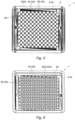
Figures 5 and 6 are top views of a packaging device according to an embodiment of the invention, -
Figures 7 and 8 are cross section views of a packaging device according to an embodiment of the invention, -
Figures 9A and 9C are cross section views of a packaging device according to an embodiment of the invention, -
Figure 10 is a top view of a packaging device according to an embodiment of the invention, -
Figure 11 is a perspective view of a packaging device according to an embodiment of the invention, -
Figures 12, 13 and14 are perspective views of a packaging device according to an embodiment of the invention, -
Figure 15 and 16 are, respectively, a perspective view and a top view of a nest of the packaging device according to an embodiment of the invention. - With reference to
Figure 1 is shown apackaging device 1 of the invention. Thepackaging device 1 of the invention is intended to contain a plurality ofmedical containers 100. Themedical containers 100 may be vials or preferably syringes, such as pre-fillable or prefilled syringes. Themedical containers 100 are intended, after filling, to contain a medical agent such as a vaccine, a medicine or a therapeutic agent. - The
medical containers 100 typically comprise anelongated barrel 102 defining a reservoir for containing said vaccine, medicine or therapeutic agent. The tube-shaped barrel 102 may be cylindrical. Themedical container 100 includes aflange 104 at aproximal end 105 of thebarrel 102, and a tip closed by a needle and/or acap 107 at adistal end 106 of themedical container 100. - The
packaging device 1 comprises supporting means which are configured to support themedical containers 100. Themedical containers 100 contained inside thepackaging device 1 may be arranged parallel to each other and to a longitudinal axis A. - With reference to
Figure 1 , the supporting means comprise a first set of supportingunits 42a which are configured to support a first plurality ofmedical containers 100a, and a second set of supportingunits 42b which are configured to support a second plurality ofmedical containers 100b. - The first supporting
units 42a and the second supportingunits 42b are arranged relative to each other so that themedical containers 100a of said first plurality ofmedical containers 100 and themedical containers 100b of said second plurality ofmedical containers 100 are supported in an inverted position, that is to say oriented in opposite directions with regard to axis A, as can be seen for example onFigures 1 ,2A ,9A, 9B ,10 and 11 . - The first set of supporting
units 42a may preferably be configured to support themedical containers 100a of said first plurality of medical containers in a first horizontal plane which is orthogonal to said longidtudinal axis A. Likewise, the second set of supportingunits 42b may be configured to support themedical containers 100b of said second plurality of medical containers in a second horizontal plane which is orthogonal to said longitudinal axis A and which is away from the first horizontal plane. - The first plane and the second plane may be spaced from each other so that at least one
medical container 100a supported by the first set of supportingunits 42a is inserted at least partially between at least twomedical containers 100b, and preferably fourmedical containers 100b, supported by the second set of supportingunits 42b. - The supporting
units 42 are preferably configured so that themedical containers 100a supported by the first set of supportingunits 42a are stored in a head-to-tail configuration with respect to themedical containers 100b supported by the second set of supportingunits 42b. By first and secondmedical containers distal end 106 of one firstmedical container 100a is located between aproximal end 105 and thedistal end 106 of the at least two, preferably four, adjacentmedical containers 100b which are positioned around. Preferably, thedistal end 106 of one firstmedical container 100a is located closer to theproximal end 105 than thedistal end 106 of one secondmedical container 100b. - The first set of supporting
units 42a may be configured to support the first plurality ofmedical containers 100a so that themedical containers 100a of the first plurality ofmedical containers 100a are arranged in parallel rows. The second set of supportingunits 42b may be configured to support the second plurality ofmedical containers 100b so that themedical containers 100b of the second plurality ofmedical containers 100b are arranged in parallel rows. Besides, the first and second sets of supportingunits packaging device 1 comprises alternate rows of medical containers of the first plurality ofmedical containers 100a and medical containers of the second plurality ofmedical containers 100b. - The supporting units of said first set of supporting
units 42a and the supporting units of said second set of supportingunits 42b are preferably arranged in staggered rows relative to each other. By supportingunits 42 of the first and second sets arranged in staggered rows relative to each other, it is meant that between four adjacent supportingunits 42 of one of the first or second set of supporting units is delimited an area which faces one supportingunit 42 of the other of the first or second set of supporting units, having regard to the longitudinal axis A. - As shown on the figures, the first set of supporting
units 42a and the second set of supportingunits 42b are configured to support theflange 104 of themedical containers flanges 104 thus lean against the corresponding supportingunits - For example, the first and second sets of supporting
units axial stops 428 are configured to support theflange 104 of onemedical container 100. The first and second axial stops 428a, 428b are preferably oriented opposite to each other. The first and second axial stops 428a, 428b may be spaced from each other so that adistal end 106 of amedical container proximal end 105 of the adjacentmedical containers distal end 106 of amedical container proximal end 105 and thedistal end 106 of amedical container medical containers 100. - The supporting units of the first and second sets of supporting
units 42a preferably delimit first andsecond apertures 420a, 420b. Each of said first andsecond apertures 420a, 420b is configured to receive onemedical container - The supporting
units 42 may comprise a guidingconduit 424 in order to allow a translational movement along axis A of themedical containers 100 relative to the supportingunits 42. - It should be noted that the supporting
units proximal end 105 of themedical containers 100, while thepackaging device 1 may further comprise lateral guidingsurfaces 46 configured to prevent a lateral movement of thedistal end 106 of themedical containers 100 with respect to a longitudinal axis A, so as to prevent collisions between adjacentmedical containers - In order to prevent the
medical containers 100 from inadvertently leaving the supportingunits 42, thepackaging device 1 preferably comprise a retaining element, such as aninternal face 62 of asealing element 6. - According to an embodiment shown on
Figure 1 , thepackaging device 1 may comprise ahousing 2, twonests 4 positioned inside thehousing 2, and at least one opening 8 leading into the housing and providing a passage for inserting or removing thenests 4 into or outside thehousing 2. A nest is a plate provided with apertures, hereinafterapertures 420, aligned according to predetermined rows, each hole being configured to receive the barrel of one medical container. Thepackaging device 1 may also comprise at least onesealing element 6 for sterilizingly closing the at least oneopening 8. Preferably, thepackaging device 1 comprises twoopposite openings 8 and twosealing elements 6. - The first set of supporting
units 42a may be arranged on afirst nest 4a, whereas the second set of supportingunits 42b may be arranged on asecond nest 4b. - The
housing 2 comprises alateral wall 2 which may extend around a preferably straight longitudinal axis A. Thehousing 2 may have four side walls 22 so that thehousing 2 may have a rectangular or square shape. Thehousing 2 defines aninternal storage volume 24. - The
internal volume 24 may be divided into several portions, for example three portions: twoaccommodation portions 24a each intended to receive anest 4, and acentral portion 24b extending between said twoaccommodation portions 24a. - The at least one or the two
openings 8 lead into saidinternal volume 24. More precisely, eachopening 8 may lead into one of theaccomodation portions 24a. Theopenings 8 may be delimited by opposite ends of thehousing 2, so that the at least one and thesecond openings 8 are opposite with respect to the axis A. As shown onFigure 1 , theopenings 8 are axial openings, through which goes the longitudinal axis A. Theopenings 8 are preferably coaxial. Theopenings 8 may be similar in shape and dimensions. Theopenings 8 preferably extend perpendicular to the longitudinal axis A, and therefore are preferably parallel to each other. The one or twoopenings 8 are configured to allow passage of thenests 4 through theseopenings 8, for example by means of a translational movement of saidnests 4 along the longitudinal axis A. Eachopening 8 may therefore face one of the twonests 4. Theopenings 8 and thenests 4 may have a complementary shape. Theopenings 8 preferably have dimensions greater than that of thenests 4. - The two
nests 4 are positioned inside theinternal volume 24. More precisely, the twonests 4 may be positioned inside theaccommodation portions 24a. Thenests 4 may have a rectangular or square plate shape, so as to correspond to the shape of thehousing 2. Thenests 4 may comprise twoopposite faces first face 40a for supportingmedical containers 100, and asecond face 40b for positioning thenests 4 inside theinternal volume 24. Thenests 4 are preferably positioned perpendicular to the longitudinal axis A, or parallel to each other. As visible onFigure 1 , thenests 4 are arranged in an inverted position relative to each other, that is to say that the second faces 40b of the twonests 4 face each other. The head to tail configuration of the twonests 4 enables themedical containers 100 supported by one of these twonests 4 to extend adjacent to themedical containers 100 supported by the other of these twonests 4, that is to say side by side, thereby reducing height of thepackaging device 1. Themedical containers 100 of bothnests 4 may extend side by side in a zone corresponding to thecentral portion 24b of theinternal volume 24. - The
first nest 4a and thesecond nest 4b may be similar. Eachnest units 42 so that the first andsecond nests medical containers 100a and a second plurality ofmedical containers 100b. For example, eachnest 4 may support 100 or 160medical containers 100. As shown onFigures 1 to 11 , thefirst nest 4a and thesecond nest 4b are distinct from each other and are removable from thehousing 2. - Each supporting
unit 42 may be configured to support aproximal end 105 of onemedical container 100. The first set of supportingunits 42a and the second set of supportingunits 42b may be arranged relative to each other in staggered rows, in quincunx, so that themedical containers 100a of the first plurality ofmedical containers 100 may extend between adjacentmedical containers 100b of the second plurality ofmedical containers 100 and conversely, themedical containers 100b of the second plurality ofmedical containers 100 may extend between adjacentmedical containers 100a of the first plurality ofmedical containers 100 in the samecentral portion 24b. - By
medical containers medical containers 100a of the first plurality ofmedical containers 100 extends amedical container 100b of the second plurality ofmedical containers 100, and conversely between four adjacentmedical containers 100b of the second plurality ofmedical containers 100 extends amedical container 100a of the first plurality ofmedical containers 100. - The supporting
units 42 of the first or second set of supporting units are preferably arranged according to a predetermined pattern. For example, the supportingunits 42 may be aligned so as to form a grid pattern of perpendicular rows, as visible for instance onFigures 10 and 11 . Alternatively, the supportingunits 42 may be arranged in staggered rows. - Preferably, the supporting
units 42 of both first and second sets of supporting units are similar to each other. - The supporting
units 42 may be arranged on thefirst face 40a of thenests 4. The supportingunits 42 may comprise anaperture 420, such as a through-hole, which may be configured to permit insertion or removal of amedical container 100 through thecorresponding nest 4. Theapertures 420 and thebarrel 102 of themedical containers 100 preferably have a complementary shape. The supportingunits 42 could only comprise theapertures 420. - The
apertures 420 of the first set of supportingunits 42a may be arranged so as to allow removal of the first plurality of medical containers 102a along a first direction of the longitudinal axis A, whereas theapertures 420 of the second set of supportingunits 42b may be arranged so as to allow removal of the second plurality of medical containers 102b along a second direction of the longitudinal axis A opposite the first direction. - The supporting
units 42 may preferably comprise at least onelateral guiding surface 422 configured to delimit a guiding conduit ortube 424, such as a tubular sleeve, for receiving and guiding amedical container 100. The guidingconduits 424 may be parallel to each other and may extend along the longitudinal axis A. Each guidingconduit 424 leads into thereception aperture 420. The guidingconduits 424 may protrude from thefirst face 40a of thenest 4. The guiding surfaces 422 and/or guidingconduits 424, and thebarrel 102 of themedical container 100, may also have a complementary shape. - The supporting
unit 42 may include anaxial stop 428, which may be delimited by an end of the guidingconduit 424, saidaxial stop 428 being configured to stop insertion of amedical container 100 into thereception aperture 420. More precisely, theflange 104 of themedical containers 100 may be designed to abut on saidaxial stop 428. In particular, the outer diameter of theflange 104 of themedical containers 100 is greater than the diameter of the guidingconduit 424 orreception aperture 420. The axial stops 428 of the first and second sets of supportingunits - The
packaging device 1, for example thenests 4, may advantageously comprise guiding means configured to guide themedical containers 100 with regard to the longitudinal axis A. The guiding means arranged on one of the twonests 4 may thus prevent or at least limit a lateral movement of themedical containers 100 which are supported by theother nest 4. As a result, the guiding means of thefirst nest 4a are configured to immobilize the second plurality ofmedical containers 100, while the guiding means of the second nest are configured to immobilize thedistal end 106 of the first plurality ofmedical containers 100. The guiding means are configured to at least radially maintain thecontainers 100, in order to prevent radial movements of thecontainers 100 during handling of thepackaging device 1. - With reference to
Figures 9A and 9B , the guiding means are configured to maintain adistal end 106 of thecontainers 100. More precisely, the guiding means may be configured to maintain adistal end 106 of thebarrel 102. For example, the guiding means are configured to maintain any device mounted on said distal tip such as for example aclosure cap 107. - The guiding means of the
first nest 4a may be similar to the guiding means of thesecond nest 4b. - The guiding means comprise a plurality of guiding units 45, each guiding unit 45 being configured to maintain a
distal end 106 of onemedical container 100. A first set of guiding units 45a may be configured to maintain an end of themedical containers 100b supported by the second set of guidingunits 42b, whereas a second set of guiding units 45b may be configured to maintain an end of themedical containers 100a supported by the first set of guidingunits 42a. The guiding units 45 of bothnests 4 may be similar to each other. The guiding units 45 may be arranged on thesecond face 40b of thenests 4. The guiding units 45 and the supportingunits 42 of asame nest 4 or set are preferably arranged in staggered rows, that is to say that the guiding units 45 extend between adjacent supportingunits 42. It should also be noted that the guiding units 45a of thefirst nest 4a may face the supportingunits 42b of thesecond nest 4b having regard to the longitudinal axis A. Similarly, the guiding units 45b of thesecond nest 4b may face the supportingunits 42a of thefirst nest 4a having regard to the longitudinal axis A. In other words, the guiding units 45 of the first orsecond nest units 42 of respectively the second orfirst nest - The guiding units 45 comprise an
aperture 48, such as a through-hole. The guiding units 45 or theaperture 48 may comprise alateral guiding surface 46 configured to stop a radial movement of amedical container 100. The guidingsurface 46 may be delimited by saidaperture 48. The distal ends 106 orbarrels 102 of themedical containers 100 and the guidingsurface 46 oraperture 48 may have a complementary shape. This guidingsurface 46 oraperture 48 may be arranged on thesecond face 40b of the nests. As a result, eachmedical container 100 is maintained by bothnests 4. This prevents radial movement of themedical containers 100 during transportation. Themedical containers 100 therefore remain parallel to each other, and preferably to the longitudinal axis A. Impacts between adjacentmedical containers 100 are thus avoided. - The two
removable sealing elements 6 are configured to close theopenings 8 so that theinternal volume 24 delimited by thehousing 2 and these two sealingelements 6 is maintained sterile. The sealingelements 6 may therefore comprise a microbial barrier. The sealingelements 6 may also be permeable to a sterilization gas, so that the interior of thepackaging device 1 can be sterilized while thesealing elements 6 close the twoopenings 8. The sterilization gas may be for instance ethylene oxide (EO). In one embodiment, one of thesealing elements 6 may comprise a Tyvek® sheet or any material that is airtight but permeable to a sterilization gas such as for example ethylene oxide, and theother sealing element 6 may comprise a different material, for example a plastic material such as a polyethylene (PE) sheet. In another embodiment, the two sealingelements 6 may comprise a Tyvek® sheet so as to permit a sterilization gas to flow through thepackaging device 1, or through a stack ofpackaging devices 1 where thesealing elements 6 ofadjacent packaging devices 1 are in contact with each other. - The
packaging device 1 may comprise a sealing bag (not shown) completely enclosing thehousing 2. The sealing is configured to keep theinternal volume 24 sterilized. This sealing bag may form the at least one sealing element. This sealing bag, or header bag, may comprise a material which is permeable to a sterilization gas, such as Tyvek®. The sealing bag may also be a plastic bag or a combination of both materials, plastic and permeable to gas sterilization. - The sealing
elements 6 are configured to be removed before removing thenests 4. The sealingelements 6 may comprise anattachement surface 60 configured to be attached to thehousing 2. Theattachement surface 60 of the sealingmembers 6 may extend all along a peripheral rim of the sealingmembers 6. Preferably, theattachment surface 60 of the sealing member is glued, for example thermo glued, on thehousing 2. - The
packaging device 1 advantageously comprises opposite bearing surfaces 28 so as to permit stacking ofseveral packaging devices 1. The bearing surfaces 28 may be located at opposite ends of thehousing 2. The opposite bearing surfaces 28 are preferably perpendicular to the longitudinal axis A, and may be parallel to each other. The opposite bearing surfaces 28 may extend around each of theopenings 8. The opposite bearing surfaces 28 may be delimited by aflange 30 extending from an end of thehousing 2. It should be noted that thesealing elements 6 may be attached to these bearing surfaces 28. - The
packaging device 1 may also comprise at least a side wall 22 configured to permit thepackaging device 1 to lie in a side rest position. This side wall may include aside bearing surface 32, which may be parallel to the longitudinal axis A, and to the guidingconduits 424 and/or themedical containers 100 so that thepackaging device 1 may rest on a side. Thepackaging device 1 preferably includes two opposite side bearing surfaces 32. In the example shown onFigure 1 , the side bearing surfaces 32 are delimited by an edge of theflanges 30. - The
packaging device 1 may comprise two opposite axial abutment surfaces 36 extending inside theinternal volume 24 so as to support thenests 4. The axial abutment surfaces 36 may protrude from an inner side of thehousing 2. Alternatively or complementarily, the axial abutment surfaces 36 may be delimited at opposite ends of a spacer, for example a spacer bar, which is interposed between thenests 4 so as to maintain at a predetermined distance. The abutment surfaces 36 are configured to stop insertion of thenests 4 inside theinternal volume 24. The abutment surfaces 36 preferably extend perpendicular to the longitudinal axis A and preferably face acorresponding opening 8. Preferably, thesecond face 40b of thenests 4 just rests on thecorresponding abutment surface 36, without further attachment. - The abutment surfaces 36 may be delimited by corresponding
shoulders 38 extending inside theinternal volume 24. Alternatively or complementarily, the abutment surfaces 36 may be delimited by ribs or protrusions arranged on an inner side of thehousing 2. - It should be noted that the
housing 2 may be devoid of such abutment surfaces 36 orshoulders 38, and may comprise other spacing means in order to keep thenests 4 separated at a predetermined distance from each other, such as a spacer element (not shown) which is interposed between thefirst nest 4a and thesecond nest 4b. - In order to prevent excessive movements of the
medical containers 100 and of thenests 4 inside thehousing 2 during handling of thepackaging device 1, the sealingelements 6 presents aninternal face 62 which may configured to hold back themedical containers 100 inside the corresponding supportingunits 42 ornests 4 and thus hold back thenests 4 inside theaccomodation portions 24a. A distance D between thisinternal face 62 and theflange 104 or end of themedical containers 100 supported by the correspondingnest 4 may be comprised between 0 mm and 10 mm. In other words, the height of theaccommodation portions 24a may be equal to the distance between the theflange 104 or end of themedical containers 100 and thesecond face 40b plus the aforementioned distance D. The height of theaccommodation portions 24a may be the distance between the abutment surfaces 36 and theextraction openings 8. - The
packaging device 1 may includelateral stopping surfaces 39 configured to limit lateral movements of thenests 4 inside theinternal volume 24. Thelateral stopping surfaces 39 may be part of an inner side surface of thehousing 2. For example, thelateral stopping surfaces 39 may correspond to a portion of thehousing 2 from which theshoulders 38 extend. Thelateral stopping surfaces 39 may face and block anedge 49 of thenests 4. - With reference to
Figures 12 to 14 is shown apackaging device 1 according to another embodiment. The features which are similar to the above-described embodiments are designated by the same numeral references. In this embodiment, the twonests 4 and, possibly thehousing 2, are molded in a single piece. - The
packaging device 1 is intended to receive themedical containers 100 in a head-to-tail configuration, as shown onfigure 14 . The guidingconduits 424 are tubes provided with theaperture 420 at a first end and theaperture 48 at a second end opposite said first end. Therefore, the guidingconduits 424 connect the twonests 4. Eachmedical container 100 is thus maintained, from itsproximal end 105 to itsdistal end 106, in a single compartment. Theproximal end 105 of eachmedical container 100 is maintained by one of the twonests 4 while thedistal end 106 is maintained by theother nest 4. - The guiding
conduits 424 may be cylindrical or may advantageously have a polygonal cross section section so as to allow a more compact storage. As shown onFigures 12 to 14 , the guidingconduits 424 are preferably hexagonal. - It should also be noted that adjacent guiding
conduits 424 share a common lateral wall portion. As a result, there is no room between adjacent guidingconduits 424. The guidingconduits 424 touch each other. - The guiding
conduits 424 extend at the same height. The end of adjacent guidingconduits 424 is at the same level. - The
packaging device 1 may be sealed by one orseveral sealing elements 6, such as Tyvek® sheet or by a sealing bag, for example under vacuum. This sealingelement 6 may be configured to retain themedical containers 100 inside the guidingconduits 424. - With reference to
Figures 15 and 16 is shown anest 4 of apackaging device 1 according to another embodiment. The features which are similar to the above-described embodiments are designated by the same numeral references. - As shown on
Figures 15 and 16 , the guidingconduits 424 may advantagesouly comprise at least two guidingtabs 424a, aslit 424b being delimited between said at least two guidingtabs 424a. This allows to reduce raw material costs and lighten thepackaging device 1. Theslits 424b extend along a direction orthogonal to thenests 4. Theslits 424b preferably extend along the whole length of the guidingconduit 424. - Advantageously, the
nests 4 may comprise slantedwalls 41 configured to guide thedistal end 106 of themedical containers 100 supported by theother nest 4 inside theapertures 48. The slantedwalls 41 preferably protrude from thesecond face 40b of thenests 4, opposite the guidingconduits 424. The slantedwalls 41 may be arranged at an end of arib 43, so as to reduce material costs. Theribs 43 may be aligned in parallel rows so as to stiffen thenests 4. Both ends of saidribs 43 may be provided with aslanted wall 41. Besides, theribs 43 preferably extend ortorgonal to thenests 4. - As visible on
Figure 16 , thepackaging device 1 may comprise keyed elements configured to allow a single predetermined positioning of thenests 4 inside thehousing 2. The keyed elements may compriseslits 44 configured to to engage ribs having a complementary shape. For example, one or several sides of thenests 4 are provided with theslits 44 while an internal wall of thehousing 2 is provided with the complementary ribs (not shown). As visible onFigure 16 , the keyed slits 44 have different shapes or locations, so that theslits 44 are advantageously asymmetric with regard to a first vertical median plane P1 and/or to a second vertical median plane P2. The first vertical median plane P1 extends at the middle and orthogonally to longitudinal sides of thenest 4, while the second median plane P2 extends at the middle and orthogonally to transversal sides of thenest 4. - With reference to
Figures 2A to 2F , another aspect of the invention is a method for removing the pluralities ofmedical containers 100 from apackaging device 1 as above described. - The method may comprise a first step of removing a first one of the two sealing
elements 6 so as to open a first of the two openings 8 (Figure 2A ), for example by peeling off the sealingelement 6 from the attachment surface 26. The method further comprises a second step of removing a first plurality ofmedical containers 100 supported by thenest 4a which faces the openedfirst opening 8. The removal of this first plurality ofmedical containers 100 may correspond to a removal of thenest 4 itself, as shown onFigures 2B and 2C . This removal may be operated by a translational movement of thenest 4 along the longitudinal axis A. The method may then comprise a third step of rotating thehousing 2 according to a 180° rotation (Figure 2D ). The method may then repeat the same above mentioned first, second and third successive steps so as to remove the second plurality ofmedical containers 100, that is to say a step of removing the remainingsealing element 6 so as to open the second of the twoopenings 8 for example by peeling off the sealingelement 6 from the attachment surface 26 (Figure 2E ) and a step of removing the remaining plurality ofmedical containers 100, for instance by removing the remainingnest 4 itself, said remainingnest 4 being removed by means of a translational movement along axis A and through said second extraction opening (Figure 2D ). Themedical containers 100 may then be filled with a medical agent, before replacing thefirst nest 4a holding themedical containers 100a and/or thesecond nest 4b holding themedical containers 100b into thehousing 2 for storage. - If the
packaging device 1 comprises asingle opening 8 configured to allow insertion or removal of thenests 4, the method may comprise a first step of removing a sealingelement 6 so as to open thisopening 8, for example by peeling off the sealingelement 6 from the attachment surface 26. The method comprises a second step of removing the first plurality ofmedical containers 100 supported by thenest 4a which faces theopening 8. The removal of this first plurality ofmedical containers 100 may correspond to a removal of thenest 4a itself. This removal may be operated by a translational movement of thenest 4a along the longitudinal axis A. The method may then comprise a third step of rotating thesecond nest 4b, more precisely a step of rotating thehousing 2, according to a 180° rotation. The method may comprise a fourth step of removing thehousing 2 itself, for example by means of an upper translational movement of thehousing 2 along axis A, so as to let thesecond nest 4b pass through theopening 8 and then allow removal of the medical containers supported by saidsecond nest 4b. Alternatively, after having rotated thesecond nest 4b or thehousing 2, the method may comprise removing a sealingelement 6 so as to open a secondary aperture, said secondary aperture facing saidsecond nest 4b and being smaller than the opposite opening 8 (said secondary aperture may face thesecond nest 4b but does not allow passage of thesecond nest 4b there through; the secondary aperture may however be dimensioned so as to permit removal of the medical containers supported by thesecond nest 4b). The method may then comprise a step of removing the remaining plurality ofmedical containers 100 without removing thesecond nest 4b, for example by means of a translational movement of saidmedical containers 100 along axis A and through said secondary aperture. Themedical containers 100 may then be filled with a medical agent, before replacing thefirst nest 4a and/or thesecond nest 4b into thehousing 2 for storage. - If the
packaging device 1 comprises a spacer arranged between thefirst nest 4a and thesecond nest 4b in order to maintain a predetermined distance between these twonests housing 2. For example, said spacer may be removed before removal of thesecond nest 4b. - It is contemplated that removal of the
medical containers 100 outside thehousing 2 may be performed by the only removal of thesemedical containers 100, without removal of thenests 4 supporting these medical containers from thehousing 2.
Claims (13)
- Packaging device (1) configured to support medical containers (100), the packaging device (1) comprising a first nest (4a) and a second nest (4b), said first nest (4a) including a first set of supporting units (42a) configured to support a proximal end (105) of a first plurality of medical containers (100a) and said second nest (4b) including a second set of supporting units (42b) configured to support a proximal end (105) of a second plurality of medical containers (100b), the first set of supporting units (42a) and the second set of supporting units (42b) being configured to support said first plurality of medical containers (100a) and said second plurality of medical containers (100b) so that the first plurality of medical containers (100a) and the second plurality of medical containers (100b) are supported in an inverted position relative to each other, wherein the first set of supporting units (42a) includes apertures (420) arranged to allow removal of the first plurality of medical containers (100a) along a first direction of a longitudinal axis (A) perpendicular to the nests (4), whereas the second set of supporting units (42b) includes apertures (420) arranged to allow removal of the second plurality of medical containers (100b) along a second direction of the longitudinal axis (A) opposite the first direction, and wherein the first nest (4a) comprises guiding means configured to maintain a distal end (106) of the second plurality of medical containers (100b) while the second nest (4b) comprises guiding means configured to maintain a distal end (106) of the first plurality of medical containers (100a), the guiding means comprising an aperture (48).
- Packaging device (1) according to claim 1, wherein the supporting units (42a) of said first set of supporting units (42a) delimit first apertures (420a), each of said first apertures (420a) being configured to receive one medical container of said first plurality of medical containers (100a), and the supporting units (42b) of said second set of supporting units (42b) delimit second apertures (420b), each of said second apertures (420a) being configured to receive one medical container of said second plurality of medical containers (100b), and said first apertures (420a) being arranged in staggered rows relative to said second apertures (420b).
- Packaging device (1) according to the preceding claim, wherein the guiding means comprise slanted walls (41) configured to guide said distal ends (106) inside the apertures (48)
- Packaging device (1) according to any of the preceding claims, wherein the supporting units (42) comprise a guiding conduit (424).
- Packaging device (1) according to the preceding claim, wherein the guiding conduits (424) each delimits at least one slit (424b).
- Packaging device (1) according to any of the preceding claims, wherein the packaging device (1) comprises at least one sealing element (6) configured to close the packaging device (1) in order to keep sterility of a volume configured to contain the medical containers (100), and said at least one sealing element (6) being permeable to a sterilization gas.
- Packaging device (1) according to any of the preceding claims, wherein the packaging device comprises:a housing (2) delimiting an internal volume (24), the two nests (4) being located inside the housing (2), andat least one opening (8) leading into the internal volume, said at least one opening (8) being configured to allow insertion or removal of at least one of the two nests (4) inside or outside the housing (2).
- Packaging device (1) according to the preceding claim, wherein the packaging device (1) comprises keyed elements configured to allow a single predetermined positioning of the nests (4a, 4b) relative to each other.
- Packaging device (1) according to any of claims 1-6, wherein the first nest (4a) and the second nest (4b) are molded in a single piece.
- Packaging device (1) according to claim 4 and the preceding claim, wherein the guiding conduit (424) has a polygonal, preferably hexagonal, shape.
- Packaging device (1) according to claim 4 and any of claims 9-10, wherein adjacent guiding conduits (424) have a shared lateral wall portion.
- Packaging device (1) according to claims 4 and any of claims 9-11, wherein the guiding conduits (424) have one end provided with the aperture (420) and an opposite end provided with the aperture (48).
- Method for removing the pluralities of medical containers (100) from a packaging device (1) according to any of claims 1 to 12, comprising the steps of:- removing the first plurality of medical containers (100a) supported by the first set of supporting units outside the packaging device (1),- turning the packaging device (1) over,- removing the second plurality of medical containers (100b) supported by the second set of supporting units.
Applications Claiming Priority (2)
| Application Number | Priority Date | Filing Date | Title |
|---|---|---|---|
| EP17306313 | 2017-10-02 | ||
| PCT/EP2018/076818 WO2019068723A1 (en) | 2017-10-02 | 2018-10-02 | Packaging device and method for removing medical containers from said packaging device |
Publications (2)
| Publication Number | Publication Date |
|---|---|
| EP3691715A1 EP3691715A1 (en) | 2020-08-12 |
| EP3691715B1 true EP3691715B1 (en) | 2024-03-27 |
Family
ID=60080732
Family Applications (1)
| Application Number | Title | Priority Date | Filing Date |
|---|---|---|---|
| EP18778528.2A Active EP3691715B1 (en) | 2017-10-02 | 2018-10-02 | Packaging device and method for removing medical containers from said packaging device |
Country Status (6)
| Country | Link |
|---|---|
| US (1) | US11547631B2 (en) |
| EP (1) | EP3691715B1 (en) |
| JP (1) | JP7203837B2 (en) |
| CN (1) | CN111163815B (en) |
| CA (1) | CA3075703A1 (en) |
| WO (1) | WO2019068723A1 (en) |
Families Citing this family (2)
| Publication number | Priority date | Publication date | Assignee | Title |
|---|---|---|---|---|
| USD937408S1 (en) * | 2020-07-03 | 2021-11-30 | Novandi Chemistry AB | Container to transport chemical substances |
| WO2023147407A2 (en) * | 2022-01-28 | 2023-08-03 | Becton, Dickinson And Company | Honeycomb cell packaging |
Family Cites Families (8)
| Publication number | Priority date | Publication date | Assignee | Title |
|---|---|---|---|---|
| GB772105A (en) | 1955-09-15 | 1957-04-10 | Albert John Gough | Improvements relating to cartons |
| US3074540A (en) * | 1959-07-31 | 1963-01-22 | American Hospital Supply Corp | Package for sterile articles |
| US5048684A (en) * | 1990-02-01 | 1991-09-17 | Becton, Dickinson And Company | Compact syringe and catheter package |
| JPH10114369A (en) * | 1996-10-08 | 1998-05-06 | Tokiwa Reitou Shokuhin Kk | Packaging structure for food and packaging method |
| JP2000085753A (en) * | 1998-09-15 | 2000-03-28 | Masaaki Inaoka | Container holding plate at the time of container boxing |
| US7963396B2 (en) | 2004-07-01 | 2011-06-21 | West Pharmaceutical Services, Inc. | Vacuum package system |
| DE102013112167A1 (en) * | 2013-11-05 | 2015-05-07 | Schott Ag | Support structure for simultaneously holding a plurality of containers for substances for medical, pharmaceutical or cosmetic applications as well as transport and packaging containers with self and method |
| DE102013114404A1 (en) | 2013-12-18 | 2015-06-18 | Schott Ag | Transport and packaging containers having a support structure for simultaneously holding a plurality of containers for medical, pharmaceutical or cosmetic applications, and methods and uses thereof |
-
2018
- 2018-10-02 CN CN201880064443.3A patent/CN111163815B/en active Active
- 2018-10-02 EP EP18778528.2A patent/EP3691715B1/en active Active
- 2018-10-02 CA CA3075703A patent/CA3075703A1/en active Pending
- 2018-10-02 US US16/652,792 patent/US11547631B2/en active Active
- 2018-10-02 WO PCT/EP2018/076818 patent/WO2019068723A1/en unknown
- 2018-10-02 JP JP2020518708A patent/JP7203837B2/en active Active
Also Published As
| Publication number | Publication date |
|---|---|
| EP3691715A1 (en) | 2020-08-12 |
| JP7203837B2 (en) | 2023-01-13 |
| US20200253824A1 (en) | 2020-08-13 |
| JP2020535887A (en) | 2020-12-10 |
| WO2019068723A1 (en) | 2019-04-11 |
| US11547631B2 (en) | 2023-01-10 |
| CN111163815A (en) | 2020-05-15 |
| CA3075703A1 (en) | 2019-04-11 |
| CN111163815B (en) | 2022-08-02 |
Similar Documents
| Publication | Publication Date | Title |
|---|---|---|
| US9408965B2 (en) | Method and system for handling and transporting syringes | |
| EP3691714B1 (en) | Packaging device configured to support medical containers and method for removing the medical containers from said packaging device | |
| ES2700123T3 (en) | Method to close cartridges, support structure to support cartridge closures and transport or packaging container | |
| JP6010109B2 (en) | Packaging container for medical container | |
| EP3345587B1 (en) | Container holding member and medical container set | |
| EP3691715B1 (en) | Packaging device and method for removing medical containers from said packaging device | |
| US20240042123A1 (en) | Holding Device Configured to Support a Plurality of Medical Containers Such as Syringes | |
| WO2014049714A1 (en) | Syringe storage container | |
| WO2014049715A1 (en) | Syringe storage container | |
| EP4233935A1 (en) | Holding device for medical containers with reinforcing ribs for increasing stiffness and reducing deflection | |
| JP6498492B2 (en) | Holder and sterilization method using the same |
Legal Events
| Date | Code | Title | Description |
|---|---|---|---|
| STAA | Information on the status of an ep patent application or granted ep patent |
Free format text: STATUS: UNKNOWN |
|
| STAA | Information on the status of an ep patent application or granted ep patent |
Free format text: STATUS: THE INTERNATIONAL PUBLICATION HAS BEEN MADE |
|
| PUAI | Public reference made under article 153(3) epc to a published international application that has entered the european phase |
Free format text: ORIGINAL CODE: 0009012 |
|
| STAA | Information on the status of an ep patent application or granted ep patent |
Free format text: STATUS: REQUEST FOR EXAMINATION WAS MADE |
|
| 17P | Request for examination filed |
Effective date: 20200326 |
|
| AK | Designated contracting states |
Kind code of ref document: A1 Designated state(s): AL AT BE BG CH CY CZ DE DK EE ES FI FR GB GR HR HU IE IS IT LI LT LU LV MC MK MT NL NO PL PT RO RS SE SI SK SM TR |
|
| AX | Request for extension of the european patent |
Extension state: BA ME |
|
| DAV | Request for validation of the european patent (deleted) | ||
| DAX | Request for extension of the european patent (deleted) | ||
| GRAP | Despatch of communication of intention to grant a patent |
Free format text: ORIGINAL CODE: EPIDOSNIGR1 |
|
| STAA | Information on the status of an ep patent application or granted ep patent |
Free format text: STATUS: GRANT OF PATENT IS INTENDED |
|
| INTG | Intention to grant announced |
Effective date: 20231027 |
|
| GRAS | Grant fee paid |
Free format text: ORIGINAL CODE: EPIDOSNIGR3 |
|
| GRAA | (expected) grant |
Free format text: ORIGINAL CODE: 0009210 |
|
| STAA | Information on the status of an ep patent application or granted ep patent |
Free format text: STATUS: THE PATENT HAS BEEN GRANTED |
|
| AK | Designated contracting states |
Kind code of ref document: B1 Designated state(s): AL AT BE BG CH CY CZ DE DK EE ES FI FR GB GR HR HU IE IS IT LI LT LU LV MC MK MT NL NO PL PT RO RS SE SI SK SM TR |
|
| REG | Reference to a national code |
Ref country code: GB Ref legal event code: FG4D |
|
| REG | Reference to a national code |
Ref country code: CH Ref legal event code: EP |
|
| REG | Reference to a national code |
Ref country code: DE Ref legal event code: R096 Ref document number: 602018067198 Country of ref document: DE |