EP2867174B1 - Vorrichtung und verfahren zur wasserreinigung mit flotation - Google Patents
Vorrichtung und verfahren zur wasserreinigung mit flotation Download PDFInfo
- Publication number
- EP2867174B1 EP2867174B1 EP13722305.3A EP13722305A EP2867174B1 EP 2867174 B1 EP2867174 B1 EP 2867174B1 EP 13722305 A EP13722305 A EP 13722305A EP 2867174 B1 EP2867174 B1 EP 2867174B1
- Authority
- EP
- European Patent Office
- Prior art keywords
- container
- water
- unit
- gassing
- tank
- Prior art date
- Legal status (The legal status is an assumption and is not a legal conclusion. Google has not performed a legal analysis and makes no representation as to the accuracy of the status listed.)
- Active
Links
- XLYOFNOQVPJJNP-UHFFFAOYSA-N water Substances O XLYOFNOQVPJJNP-UHFFFAOYSA-N 0.000 title claims description 98
- 238000000034 method Methods 0.000 title claims description 30
- 238000005188 flotation Methods 0.000 title description 32
- 238000001914 filtration Methods 0.000 claims description 58
- 238000005189 flocculation Methods 0.000 claims description 46
- 230000016615 flocculation Effects 0.000 claims description 46
- 239000012528 membrane Substances 0.000 claims description 46
- 238000000926 separation method Methods 0.000 claims description 40
- 239000008394 flocculating agent Substances 0.000 claims description 27
- 239000007788 liquid Substances 0.000 claims description 25
- 239000000919 ceramic Substances 0.000 claims description 17
- 239000000470 constituent Substances 0.000 claims description 15
- 239000013535 sea water Substances 0.000 claims description 13
- 238000004140 cleaning Methods 0.000 claims description 11
- 230000003311 flocculating effect Effects 0.000 claims description 7
- 239000011148 porous material Substances 0.000 claims description 7
- 238000005374 membrane filtration Methods 0.000 claims description 5
- 238000011144 upstream manufacturing Methods 0.000 claims description 3
- 238000001471 micro-filtration Methods 0.000 claims description 2
- 238000000108 ultra-filtration Methods 0.000 claims description 2
- 239000007789 gas Substances 0.000 description 52
- 239000000203 mixture Substances 0.000 description 15
- 238000009300 dissolved air flotation Methods 0.000 description 12
- 239000000126 substance Substances 0.000 description 11
- 238000000746 purification Methods 0.000 description 8
- 238000010612 desalination reaction Methods 0.000 description 7
- 150000003839 salts Chemical class 0.000 description 7
- 239000007787 solid Substances 0.000 description 7
- 238000001223 reverse osmosis Methods 0.000 description 6
- 239000002245 particle Substances 0.000 description 5
- 239000002351 wastewater Substances 0.000 description 5
- 238000005273 aeration Methods 0.000 description 4
- 230000002209 hydrophobic effect Effects 0.000 description 4
- 239000008213 purified water Substances 0.000 description 4
- 230000000630 rising effect Effects 0.000 description 4
- KRKNYBCHXYNGOX-UHFFFAOYSA-N citric acid Chemical compound OC(=O)CC(O)(C(O)=O)CC(O)=O KRKNYBCHXYNGOX-UHFFFAOYSA-N 0.000 description 3
- 239000013505 freshwater Substances 0.000 description 3
- 238000002347 injection Methods 0.000 description 3
- 239000007924 injection Substances 0.000 description 3
- XEEYBQQBJWHFJM-UHFFFAOYSA-N iron Substances [Fe] XEEYBQQBJWHFJM-UHFFFAOYSA-N 0.000 description 3
- 239000007791 liquid phase Substances 0.000 description 3
- 239000005416 organic matter Substances 0.000 description 3
- 230000003204 osmotic effect Effects 0.000 description 3
- 239000000243 solution Substances 0.000 description 3
- 241000894006 Bacteria Species 0.000 description 2
- OKTJSMMVPCPJKN-UHFFFAOYSA-N Carbon Chemical compound [C] OKTJSMMVPCPJKN-UHFFFAOYSA-N 0.000 description 2
- 241000700605 Viruses Species 0.000 description 2
- 230000015572 biosynthetic process Effects 0.000 description 2
- 239000011362 coarse particle Substances 0.000 description 2
- 238000004891 communication Methods 0.000 description 2
- 239000003651 drinking water Substances 0.000 description 2
- 235000020188 drinking water Nutrition 0.000 description 2
- 238000005265 energy consumption Methods 0.000 description 2
- 238000002474 experimental method Methods 0.000 description 2
- 239000012530 fluid Substances 0.000 description 2
- 238000002309 gasification Methods 0.000 description 2
- 239000004021 humic acid Substances 0.000 description 2
- 239000004615 ingredient Substances 0.000 description 2
- 238000009285 membrane fouling Methods 0.000 description 2
- RVTZCBVAJQQJTK-UHFFFAOYSA-N oxygen(2-);zirconium(4+) Chemical compound [O-2].[O-2].[Zr+4] RVTZCBVAJQQJTK-UHFFFAOYSA-N 0.000 description 2
- 230000036961 partial effect Effects 0.000 description 2
- 238000005192 partition Methods 0.000 description 2
- 230000002829 reductive effect Effects 0.000 description 2
- 230000000717 retained effect Effects 0.000 description 2
- HBMJWWWQQXIZIP-UHFFFAOYSA-N silicon carbide Chemical compound [Si+]#[C-] HBMJWWWQQXIZIP-UHFFFAOYSA-N 0.000 description 2
- 229910010271 silicon carbide Inorganic materials 0.000 description 2
- 239000003053 toxin Substances 0.000 description 2
- 231100000765 toxin Toxicity 0.000 description 2
- 108700012359 toxins Proteins 0.000 description 2
- 229910001928 zirconium oxide Inorganic materials 0.000 description 2
- 229910018072 Al 2 O 3 Inorganic materials 0.000 description 1
- 239000004952 Polyamide Substances 0.000 description 1
- 239000005708 Sodium hypochlorite Substances 0.000 description 1
- 239000002253 acid Substances 0.000 description 1
- 125000000217 alkyl group Chemical group 0.000 description 1
- 229910052782 aluminium Inorganic materials 0.000 description 1
- XAGFODPZIPBFFR-UHFFFAOYSA-N aluminium Chemical compound [Al] XAGFODPZIPBFFR-UHFFFAOYSA-N 0.000 description 1
- 238000013459 approach Methods 0.000 description 1
- 125000003118 aryl group Chemical group 0.000 description 1
- 244000052616 bacterial pathogen Species 0.000 description 1
- 230000005540 biological transmission Effects 0.000 description 1
- 125000003178 carboxy group Chemical group [H]OC(*)=O 0.000 description 1
- 229910010293 ceramic material Inorganic materials 0.000 description 1
- 239000003795 chemical substances by application Substances 0.000 description 1
- 238000005056 compaction Methods 0.000 description 1
- 239000012141 concentrate Substances 0.000 description 1
- 238000009833 condensation Methods 0.000 description 1
- 230000005494 condensation Effects 0.000 description 1
- 229920001577 copolymer Polymers 0.000 description 1
- 238000000354 decomposition reaction Methods 0.000 description 1
- 230000001419 dependent effect Effects 0.000 description 1
- 230000008021 deposition Effects 0.000 description 1
- 238000011161 development Methods 0.000 description 1
- 238000004090 dissolution Methods 0.000 description 1
- 230000007613 environmental effect Effects 0.000 description 1
- 238000001704 evaporation Methods 0.000 description 1
- 230000008020 evaporation Effects 0.000 description 1
- 230000002349 favourable effect Effects 0.000 description 1
- -1 for example Chemical class 0.000 description 1
- 125000000524 functional group Chemical group 0.000 description 1
- 230000005484 gravity Effects 0.000 description 1
- 229910001385 heavy metal Inorganic materials 0.000 description 1
- 239000012535 impurity Substances 0.000 description 1
- 230000010354 integration Effects 0.000 description 1
- 150000002500 ions Chemical class 0.000 description 1
- 229910052742 iron Inorganic materials 0.000 description 1
- 229920002521 macromolecule Polymers 0.000 description 1
- 239000000463 material Substances 0.000 description 1
- 244000005700 microbiome Species 0.000 description 1
- 238000009282 microflotation Methods 0.000 description 1
- 238000002156 mixing Methods 0.000 description 1
- 239000007800 oxidant agent Substances 0.000 description 1
- TWNQGVIAIRXVLR-UHFFFAOYSA-N oxo(oxoalumanyloxy)alumane Chemical compound O=[Al]O[Al]=O TWNQGVIAIRXVLR-UHFFFAOYSA-N 0.000 description 1
- 239000000575 pesticide Substances 0.000 description 1
- 229920002647 polyamide Polymers 0.000 description 1
- 229920005597 polymer membrane Polymers 0.000 description 1
- 239000004810 polytetrafluoroethylene Substances 0.000 description 1
- 229920001343 polytetrafluoroethylene Polymers 0.000 description 1
- 238000011045 prefiltration Methods 0.000 description 1
- 238000003825 pressing Methods 0.000 description 1
- 238000002203 pretreatment Methods 0.000 description 1
- 238000004540 process dynamic Methods 0.000 description 1
- 238000012545 processing Methods 0.000 description 1
- 230000002441 reversible effect Effects 0.000 description 1
- 238000007790 scraping Methods 0.000 description 1
- 238000012216 screening Methods 0.000 description 1
- 239000010802 sludge Substances 0.000 description 1
- SUKJFIGYRHOWBL-UHFFFAOYSA-N sodium hypochlorite Chemical compound [Na+].Cl[O-] SUKJFIGYRHOWBL-UHFFFAOYSA-N 0.000 description 1
- 230000003068 static effect Effects 0.000 description 1
- 230000007704 transition Effects 0.000 description 1
- 238000009281 ultraviolet germicidal irradiation Methods 0.000 description 1
Images

Classifications
-
- C—CHEMISTRY; METALLURGY
- C02—TREATMENT OF WATER, WASTE WATER, SEWAGE, OR SLUDGE
- C02F—TREATMENT OF WATER, WASTE WATER, SEWAGE, OR SLUDGE
- C02F9/00—Multistage treatment of water, waste water or sewage
-
- B—PERFORMING OPERATIONS; TRANSPORTING
- B01—PHYSICAL OR CHEMICAL PROCESSES OR APPARATUS IN GENERAL
- B01D—SEPARATION
- B01D21/00—Separation of suspended solid particles from liquids by sedimentation
- B01D21/0039—Settling tanks provided with contact surfaces, e.g. baffles, particles
- B01D21/0042—Baffles or guide plates
-
- B—PERFORMING OPERATIONS; TRANSPORTING
- B01—PHYSICAL OR CHEMICAL PROCESSES OR APPARATUS IN GENERAL
- B01D—SEPARATION
- B01D21/00—Separation of suspended solid particles from liquids by sedimentation
- B01D21/0084—Enhancing liquid-particle separation using the flotation principle
-
- B—PERFORMING OPERATIONS; TRANSPORTING
- B01—PHYSICAL OR CHEMICAL PROCESSES OR APPARATUS IN GENERAL
- B01D—SEPARATION
- B01D21/00—Separation of suspended solid particles from liquids by sedimentation
- B01D21/01—Separation of suspended solid particles from liquids by sedimentation using flocculating agents
-
- C—CHEMISTRY; METALLURGY
- C02—TREATMENT OF WATER, WASTE WATER, SEWAGE, OR SLUDGE
- C02F—TREATMENT OF WATER, WASTE WATER, SEWAGE, OR SLUDGE
- C02F1/00—Treatment of water, waste water, or sewage
- C02F1/24—Treatment of water, waste water, or sewage by flotation
-
- C—CHEMISTRY; METALLURGY
- C02—TREATMENT OF WATER, WASTE WATER, SEWAGE, OR SLUDGE
- C02F—TREATMENT OF WATER, WASTE WATER, SEWAGE, OR SLUDGE
- C02F1/00—Treatment of water, waste water, or sewage
- C02F1/44—Treatment of water, waste water, or sewage by dialysis, osmosis or reverse osmosis
-
- C—CHEMISTRY; METALLURGY
- C02—TREATMENT OF WATER, WASTE WATER, SEWAGE, OR SLUDGE
- C02F—TREATMENT OF WATER, WASTE WATER, SEWAGE, OR SLUDGE
- C02F1/00—Treatment of water, waste water, or sewage
- C02F1/52—Treatment of water, waste water, or sewage by flocculation or precipitation of suspended impurities
-
- C—CHEMISTRY; METALLURGY
- C02—TREATMENT OF WATER, WASTE WATER, SEWAGE, OR SLUDGE
- C02F—TREATMENT OF WATER, WASTE WATER, SEWAGE, OR SLUDGE
- C02F1/00—Treatment of water, waste water, or sewage
- C02F1/44—Treatment of water, waste water, or sewage by dialysis, osmosis or reverse osmosis
- C02F1/444—Treatment of water, waste water, or sewage by dialysis, osmosis or reverse osmosis by ultrafiltration or microfiltration
-
- C—CHEMISTRY; METALLURGY
- C02—TREATMENT OF WATER, WASTE WATER, SEWAGE, OR SLUDGE
- C02F—TREATMENT OF WATER, WASTE WATER, SEWAGE, OR SLUDGE
- C02F1/00—Treatment of water, waste water, or sewage
- C02F1/52—Treatment of water, waste water, or sewage by flocculation or precipitation of suspended impurities
- C02F1/5236—Treatment of water, waste water, or sewage by flocculation or precipitation of suspended impurities using inorganic agents
- C02F1/5245—Treatment of water, waste water, or sewage by flocculation or precipitation of suspended impurities using inorganic agents using basic salts, e.g. of aluminium and iron
-
- C—CHEMISTRY; METALLURGY
- C02—TREATMENT OF WATER, WASTE WATER, SEWAGE, OR SLUDGE
- C02F—TREATMENT OF WATER, WASTE WATER, SEWAGE, OR SLUDGE
- C02F2101/00—Nature of the contaminant
- C02F2101/30—Organic compounds
-
- C—CHEMISTRY; METALLURGY
- C02—TREATMENT OF WATER, WASTE WATER, SEWAGE, OR SLUDGE
- C02F—TREATMENT OF WATER, WASTE WATER, SEWAGE, OR SLUDGE
- C02F2101/00—Nature of the contaminant
- C02F2101/30—Organic compounds
- C02F2101/32—Hydrocarbons, e.g. oil
- C02F2101/327—Polyaromatic Hydrocarbons [PAH's]
-
- C—CHEMISTRY; METALLURGY
- C02—TREATMENT OF WATER, WASTE WATER, SEWAGE, OR SLUDGE
- C02F—TREATMENT OF WATER, WASTE WATER, SEWAGE, OR SLUDGE
- C02F2103/00—Nature of the water, waste water, sewage or sludge to be treated
- C02F2103/08—Seawater, e.g. for desalination
-
- Y—GENERAL TAGGING OF NEW TECHNOLOGICAL DEVELOPMENTS; GENERAL TAGGING OF CROSS-SECTIONAL TECHNOLOGIES SPANNING OVER SEVERAL SECTIONS OF THE IPC; TECHNICAL SUBJECTS COVERED BY FORMER USPC CROSS-REFERENCE ART COLLECTIONS [XRACs] AND DIGESTS
- Y02—TECHNOLOGIES OR APPLICATIONS FOR MITIGATION OR ADAPTATION AGAINST CLIMATE CHANGE
- Y02A—TECHNOLOGIES FOR ADAPTATION TO CLIMATE CHANGE
- Y02A20/00—Water conservation; Efficient water supply; Efficient water use
- Y02A20/124—Water desalination
- Y02A20/131—Reverse-osmosis
Definitions
- the present application relates to a device for purifying water according to the preamble of claim 1 and to a method for purifying water according to claim 21.
- Reverse osmosis or reverse osmosis is a physical process for concentrating substances dissolved in liquids, in which the natural osmosis process is reversed with pressure. In this case, a greater pressure than the natural osmotic pressure is generated on one side of a semipermeable membrane.
- the seawater is pressed to overcome the osmotic pressure under high pressure through a semipermeable membrane of polyamide, PTFE or sulfonated co-polymers having a pore diameter of 5x10 -7 to 5x10 -6 mm.
- the semipermeable membrane acts like a filter and only lets through water molecules
- the membrane while salts and other substances, such as bacteria and viruses or even toxins, such as heavy metals, are retained, so that clean drinking water is obtained.
- the osmotic pressure increases with increasing salt concentration, so that the process would eventually come to a halt. To counteract this, the concentrate is discharged.
- One of the biggest problems with reverse osmosis is the deposition of retained or filtered matter on the reverse -osomal membrane, which causes membrane fouling.
- the water to be purified should be as free as possible of coarse particles, organic matter and impurities before it enters the reverse osmosis system. Accordingly, the seawater desalination process requires thorough pre-purification of the seawater to be desalinated.
- pre-filters which allow a separation of coarse particles up to a particle size of 20 microns.
- Additional activated carbon filters allow the separation of organic matter, such as pesticides or other toxins. It is also possible to establish UV irradiation in a pre-cleaning step, whereby a large number of health-threatening germs, such as viruses and bacteria, can be killed.
- DAF Dissolved Air Flotation
- Flotation is a gravity separation process used to separate solid-liquid or liquid-liquid systems.
- gas bubbles for example, from air, generated and introduced into the liquid phase, wherein in the liquid phase located hydrophobic particles, such as organic substances, attach to these also hydrophobic bubbles and caused by the gas bubbles increased buoyancy rise to the surface ,
- these agglomerates accumulate to form a sludge layer which is easily mechanically separable.
- the flotation in particular DAF, is suitable for the separation of very low-density suspended matter, such as microalgae or for the separation of organic hydrophobic ingredients.
- a DAF device comprises a flocculation unit for flocculating the particulates and organic ingredients and a so-called flotation cell.
- the polluted water to be purified provided with a suitable flocculating agent, enters from the flocculating unit into the contact zone of the flotation cell into which gas supersaturated water is injected and comes into direct contact with the water to be purified entering the contact zone. Due to the reduced pressure prevailing in the flotation cell, the gas bubbles escape from the injected solution and small bubbles with diameters of 10 to 100 ⁇ m are formed. This bladder swarm is called "white water".
- the DAF method allows very good separation of microalgae and other microorganisms from highly loaded waste water, but requires a relatively high energy consumption due to the introduction of air by means of a saturation column in the recycled partial flow. It is also not possible to treat very cloudy and heavily muddy water with DAF.
- An object of the present invention was therefore to provide an apparatus and a method with which the disadvantages of the known flotation, in particular the DAF process can be reduced or overcome with its high energy consumption.
- a device for purifying water in particular salt water or seawater, comprises at least one container for holding water mixed with at least one flocculating agent for separating off organic and optionally biological constituents contained in the water, such as e.g. Microalgae, at least one gassing unit disposed in the container, and further at least one filtration unit.
- the at least one container may also be referred to as flotation cell or cleaning basin.
- the container comprises at least one contact zone for contacting the water added with the flocculating agent, e.g. the liquid stream from the flocculation unit into the container, with at least one gas, in particular air, to form a flake-gas bubble agglomerate and at least one separation zone for separating the flocculated organic constituents which have been expelled by the gas.
- the flocculating agent e.g. the liquid stream from the flocculation unit into the container
- at least one gas in particular air
- the at least one gassing unit is arranged from one or more ceramic gassing membranes with a mean pore size of 2 ⁇ m in the contact zone of the container and the at least one filtration unit in the separation zone of the container.
- the present device is characterized in that the gassing unit is directly connected to a compressed gas line or a gas cylinder, so that the at least one gas for forming the flake gas bubble agglomerate directly via the at least one arranged in the contact zone of the gasification unit without using a liquid carrier is injected into this container. As described later in detail, the gas is thus introduced directly into the container without prior dissolution or pressing into a liquid.
- the at least one filtration unit is preferably arranged offset along a horizontal plane of the container to the gassing unit.
- "Offset" in the sense of the present invention means that the filtration unit is arranged laterally or spatially or horizontally offset from the gassing unit; Filtration unit and gassing unit are therefore not arranged vertically one above the other and do not overlap, but are preferably adjacent to each other or adjacent to each other along a horizontal plane of the container arranged. The gas bubbles emerging from the gassing unit therefore do not strike directly and directly on a vertically above the gassing unit lying filtration unit. Filtration unit and gassing unit are arranged in spatially different areas or zones of the container.
- the at least one container may be preceded by a flocculation unit for receiving the water to be purified and at least one flocculating agent for flocculating organic constituents contained in the water.
- the flocculation unit and the container are preferably in fluid communication with each other and the flocculation in the flocculation organic components can be transported by means of a liquid flow from the flocculation in the container.
- the flocculation unit may either be formed as a unit separate from the container or integrated into the container, i. be formed integrally with the container.
- the flocculation unit may comprise at least one, preferably two, section or area separated from the actual flotation cell. In this separated area, the water to be purified and the flocculating agent are introduced and optionally mixed intensively using a stirrer. The water added with the flocculating agent may then be e.g. either into a second area of the container separated from the flotation cell, in which e.g. additional flocculants may be added, or directly into the flotation cell in the contact zone of the flotation cell, i. fed in the direction of the gassing unit.
- the present device thus combines the process of flotation with membrane filtration.
- the additional membrane filtration results in a better purification of the water than by mere flotation.
- the membrane filtration can be carried out more effectively since particles have already been removed by the flotation prior to filtration.
- the combination of flotation and filtration in a single vessel improves process dynamics by allowing a smaller flotation cell vessel to be used and higher throughput.
- no recycle stream ie no recycle as in a DAF more necessary, as will be explained below. This, in turn, means that the energy requirement for pumps is smaller and the overall space requirement is lower. Due to the present process, very little wastewater is produced since the solid layer can be separated directly with a very small water content. All of these factors have a positive impact on the economics and environmental performance of the present process. With the present method are both process integration and process intensification possible, which lead to a smaller space requirement and lower investment and operating costs and also improve the cleaning result.
- the container used in the present apparatus for example in the form of a flotation cell, is preferably in the form of a container or basin of length a, width b and height h open on an upper side opposite the bottom surface, preferably a> b and a> h is. Width b and height h can be the same or different.
- the container thus preferably comprises two elongated side walls and two short side walls. Accordingly, a container is particularly suitable as a flotation cell or cleaning basin, which has a rectangular configuration.
- the container has six rectangular surfaces, the surfaces formed from axb as the bottom surface, the open surface opposite the bottom surface, the surfaces formed from axh as the elongated sidewalls, and the surfaces formed from bxh as the short sidewalls of the container to be discribed.
- the above-mentioned horizontal plane of the container preferably runs parallel to the length a of the container.
- the contact zone is the region in which the liquid flow from the flocculation unit comes into contact with the introduced gas and formation of a flake gas bubble agglomerate occurs.
- the region of the contact zone is preferably determined by the arrangement or positioning of the gassing unit in the container or basin bottom.
- the region of the contact zone may have a length which is in a range between 0.15-0.25 times, preferably 0.2 times the length a of the container, and has a width which corresponds to the width b of the container.
- the height of the contact zone is determined by the liquid level of the water added to the flocculating agent in the container.
- the separation zone is the area of the container in which the separation of the flocculated organic constituents driven by the gas takes place from the water.
- This separation of the distended organic agglomerates is preferably carried out on the surface by means of suitable mechanical means, e.g. Clearing equipment e.g. in the form of scrapers. Such agents are known in the art.
- the separation zone comprises a region of the container which is larger than the contact zone.
- the separation zone preferably comprises a region having a length which corresponds to 0.75-0.85 times, preferably 0.8 times, the length a of the container.
- the Width of the separation zone corresponds to the width b of the container.
- the height of the separation zone is determined by the liquid level of the water added to the flocculating agent in the container.
- the transition between contact zone and separation zone in the container is preferably fluid, i. there is no sharp spatial separation of contact zone and separation zone in the container. Only a baffle described below can be considered as a kind of spatial boundary or dividing line between contact zone and separation zone.
- the at least one filtration unit is arranged in the container below the layer formed by the swollen, flocculated organic constituents. It is particularly preferred if the at least one filtration unit is arranged at the bottom of the container within the separation zone. In other words, the filtration unit is submerged in the separation zone of the container.
- the filtration unit has a rectangular shape adapted to the flotation cell.
- the length of the filtration unit preferably corresponds to 0.5 to 0.7 times, more preferably 0.6 times the length a of the flotation cell.
- the width of the filtration unit preferably corresponds to 0.6 to 0.9 times, more preferably 0.8 times the width b of the flotation cell.
- the filtration unit does not extend completely over the entire width of the container, but rather has a small distance from the elongated side walls of the container.
- the filtration unit is designed so that it corresponds in a range between 0.1 to 0.4 times, preferably 0.2 to 0.3 times the height h of the container.
- other dimensions for the coming to use filtration unit are conceivable.
- the at least one filtration unit is in the form of a ceramic filtration membrane, in particular in the form of a ceramic micro- or ultrafiltration membrane.
- ceramic filtration membranes have a high chemical resistance and a long life.
- ceramic filtration membranes are more water-permeable and less prone to fouling because they are more hydrophilic than polymer membranes. Due to their mechanical stability, no pre-screening is required.
- Particularly suitable is a membrane module having an average pore size of 20 nm to 500 nm, preferably from 100 nm to 300 nm, particularly preferably of 200 nm.
- the preferred filtration membrane module may consist of multiple plates, one or more tubes or other geometric shapes.
- Ceramic material has proven ⁇ -Al 2 O 3 , but other ceramic oxides and non-oxides such as silicon carbide or zirconium oxide for use in the filtration unit can be used.
- the device comprises at least one means for aeration of the filtration unit in order to ventilate the at least one filtration unit in a suitable manner.
- a suitable aeration means may be in the form of perforated tubes.
- the aeration means may be fed with air to apply large shear forces to the surface of the filtration unit to prevent or minimize fouling on the membrane surface.
- suitable chemical substances such as citric acid to prevent inorganic fouling or a suitable oxidizing agent, such as sodium hypochlorite to reduce the biological fouling.
- the smallest gas bubbles are introduced into the cleaning basin via a gassing unit located in the contact zone.
- the gassing unit used can consist of one or more plates or disks, tubes or other geometric shapes. Ceramic has proven to be a particularly suitable material, in particular aluminum oxide ⁇ -AL 2 O 3 . However, other ceramic oxides and non-oxides such as silicon carbide or zirconium oxide can be used. It can therefore also be called a membrane.
- the at least one gassing unit used therein is composed of 1 to 10, preferably 2 to 6, particularly preferably 4 to 6 gassing membranes.
- the ceramic gassing membranes used have a mean pore size of 2 ⁇ m.
- the mean bubble diameter of the gas bubbles introduced via the gassing membrane, in particular air bubbles can be between 10 ⁇ m and 100 ⁇ m, preferably from 20 microns to 80 microns, more preferably 50 microns.
- the generation of bubbles on the gassing membrane can be influenced in particular by means of a suitable gas volume flow and pressure. The higher the pressure, the more and the bigger bubbles are created.
- the set volume flow plays in the present case only a minor role.
- the gassing membranes are arranged parallel to one another along the width of the container.
- the number of gassing membranes depends on the width of the container and the dimensions of the individual gassing membrane.
- at least four parallel gassing membranes for generating the gas bubbles, in particular air bubbles, at the bottom of the gassing, that is, the container for receiving the offset with the flocculation water be arranged.
- the gassing membranes are arranged vertically one above the other. In this case, the number of gassing membranes arranged one above the other depends on the height of the container and the level of the container.
- the arrangement of the gassing unit on the container bottom can be such that the rising gas bubbles do not reach into a region between a first guide plate (see also below) and a side wall of the container.
- the gassing unit is preferably arranged at a distance from a side wall, in particular a short side wall, of the gassing container, this distance of the gassing membrane from a side wall corresponding to the distance or the opening between a baffle and a side wall of the gassing container.
- gas injection is accomplished by direct injection of a gas, such as air in the form of finest bubbles across the gassing membrane.
- a gas such as air in the form of finest bubbles across the gassing membrane.
- the advantage of a direct injection of a gas is in particular that the recycle stream and the saturation column are omitted, since the gas, such as the air, can be removed directly from a compressed air line or a gas cylinder. This is particularly favorable in the case of the pre-purification of seawater for desalination, since the increased temperature and the increased salt content of the seawater make air saturation within the scope of the DAF more difficult since less air dissolves in the recycle stream. Thus, no compaction energy is needed to achieve a high pressure level throughout the recycle stream.
- At least one first baffle for directing the flocculated organic constituents which are distended by the gas from the contact zone into the separation zone is furthermore arranged.
- This first baffle is preferably arranged parallel to the two opposite short side walls of the gassing container.
- the width b 'of this at least first guide plate is preferably equal to the width b of the gassing container and thus equal to the length of the short side wall.
- the height h 'of the at least first baffle is, however, smaller than the height h of the container, so that a communication between the contact zone and the separation zone is ensured in the gassing.
- the at least first baffle is preferably movable or rigidly arranged at the bottom of the container.
- the arrangement of the first guide plate is preferably such that between the first guide plate and the bottom of the container an angle between 90 ° and 50 °, preferably between 80 ° and 55 °, particularly preferably between 75 ° and 60 °.
- the first baffle is preferably oriented so that it is inclined away from the contact zone at an angle of less than 90 ° in the direction of the separation zone, whereby the liquid stream entrained with the gas bubbles, for example in the form of a liquid with flake gas bubble agglomerates directed way from the contact zone along the inclined first guide plate toward the separation zone and thereby preferably directly to the surface of the liquid in the gasification tank in the separation zone is passed.
- the first guide plate is arranged at an angle of 60 ° with respect to the container bottom, whereby a steering of the flake-air bubble aggregates from the contact zone into the separation zone and here in particular above the filtration unit.
- At least one second baffle may be attached to the at least one first baffle in the region of the contact zone be arranged opposite elongated side walls of the container.
- the at least second baffle is preferably attached to the side edges which define the upwardly open side of the container, the opposite elongated side walls of the container by suitable fastening means.
- the second baffle is preferably arranged so that there is a gap between the bottom of the container and the second baffle. In other words, the second baffle has no contact with the bottom of the container.
- the height h "of the second baffle is thus smaller than the height h of the container, wherein the width b" of the second baffle is preferably equal to the width b of the container and thus corresponds in width to the short side wall of the container.
- the at least first baffle plate and the at least second baffle plate are offset from one another and arranged opposite one another, so that a meandering flow of the water introduced into the container and mixed with the flocculating agent can be effected.
- An opposing arrangement is to be understood herein as meaning that the first and second baffles are secured to opposite sides of the container.
- the first baffle is disposed at the bottom of the container and spaced from the opposite open side of the container, while the second baffle is preferably secured to the side edges of the elongate side walls of the container which define the upwardly open side of the container is that there is a gap between the bottom of the container and the second baffle.
- the second baffle can be connected to the side edges of the elongate side walls of the container which delimit the upwardly open side of the container at an angle of between 90 ° and 70 °, preferably between 85 ° and 75 °, particularly preferably at an angle of 80 ° be arranged on the container bottom opposite the open side of the container.
- the second guide plate is preferably oriented so that it is inclined away from the separation zone at an angle of less than 90 ° in the direction of one of the particularly short side walls of the container. It is also conceivable that the second baffle is inclined away from the first short side wall of the container.
- the filtration unit, the first guide plate, the second guide plate and the gassing unit are arranged one behind the other along the length a of the container. If you follow z.
- the stream of the water added with the flocculating agent initially enters the second baffle directly on entry into the container, through which the stream is selectively directed in the direction of the gassing unit arranged at the bottom of the container; the stream of water added with the flocculating agent is mixed with at least one gas, in particular air, at the gassing unit, and the flake gas bubble agglomerate thus formed is directed towards the separation zone and the filtration unit through the first guide plate, which is preferably inclined.
- the present system accordingly has a horizontal operation.
- the water added from the flocculation unit on the open upper side of the container can be introduced into the flocculating unit, i.e., the flocculating unit.
- the flocculant mixture can be introduced into the container from above. If the flocculent mixture is introduced into the container from above, it is particularly preferred if the water added with the flocculating agent is introduced into a region of the container bounded by the second guide plate and the short side wall closest to the second guide plate.
- the second guide plate may have an angle of inclination towards the nearest short side wall of the container.
- the size of the angle of inclination of the second guide plate is preferably adjustable as a function of the amount of water flowing in with a flocculating agent.
- the inclination angle can be adjusted so that the second guide plate leads in the direction of the side wall of the gassing container, but this does not touch, so that an entry or passage opening or area between the second baffle and the nearest short side wall of the container remains.
- the passage area for the flocculating agent added water (flocculation mixture) flowing from the flocculation into the container is preferably set so that the flow velocity of the flocculation mixture at the passage area between the second baffle and short side wall of the container is large. It is Z. B. conceivable that the passage area has a width of 1-5 cm.
- the second baffle allows a uniform entry of the flocculation mixture over the entire width of the container.
- the contact zone K which forms between the second baffle and the short side wall, be determined by the size of the passage area.
- the preferably low passage area of the flocculation mixture between the second baffle plate and the short side wall of the container and the resulting high flow velocity of the flocculation mixture through the passage gap means that no gas bubbles rising from the gassing unit rise up against the direction of entry of the flocculation mixture into the container.
- flocculation unit flocculated water or flocculation mixture In addition to the above-mentioned entry of flocculant-added water from the flocculation unit on the upper open side of the container, it is also generally possible for flocculation unit flocculated water or flocculation mixture to be parallel and spaced a short distance from the bottom of the container to enter the container, in particular to inject. The distance between the bottom of the container and the entry of the flocculation mixture is dependent on the total size of the container.
- the addition of the at least one flocculating agent to the water to be purified takes place for flocculation of organic constituents contained in the water in at least one flocculation unit upstream of the tank.
- the flocculation of the dissolved organic constituents contained in the water to be purified preferably takes place by means of chemical substances known for this purpose, the use of Fe 3+ or Al 3+ salts such as, for example, FeCl 3 having proved to be particularly advantageous.
- the water added in the flocculation unit with the flocculating agent is then preferably transferred into the at least one container in the form of a liquid stream in which the liquid stream is mixed with gas bubbles, in particular air bubbles, introduced into the container via a gassing unit.
- gas bubbles in particular air bubbles
- the thereby forming agglomerate of gas bubbles and flocculated organic components rises to the surface of the liquid in the container, collects there and is mechanically separated.
- the water thus freed from the majority of the organic components is finally drawn off through the filtration unit arranged on the bottom surface of the container and fed to further treatment steps.
- the present method accordingly represents a hybrid process of microflotation and membrane filtration in a single singular device unit.
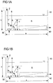
- FIG. 1 a A general structure of a first embodiment of the device according to the invention is in Fig. 1 a shown.
- the side view of Fig. 1a comprises a container 10, a gassing unit 30, a filtration unit 40, a first baffle 1 and a second baffle 2.
- the container 10 has an upper side which is open and a bottom surface opposite to this upper side.
- the gassing unit 30, the first baffle 1 and the filtration unit 40 are arranged along this bottom surface and on this bottom surface.
- the container 10 comprises, in addition to the upper open side and the bottom surface, two opposite elongate side walls and two opposite short side walls. Overall, the container 10 in the form of a cuboid with a length a, a width b and a height h is formed. The elongated side walls of the container are determined by the length a and the height h, while the dimensions of the short side walls are defined by the width b and the height h of the container.
- the length a is z. B. 1 m, the width b 0.61 m and the height h 0.5 m.
- the gassing unit 30 is composed of four individual gassing membranes at a distance of e.g. 0.1 m from a first short side wall with the width b arranged.
- the gassing unit 30 extends over the entire width b of the container 10 and may consist of several slices, plates, tubes or other geometric shapes.
- this gassing unit 30 is the second baffle 2, which is also located at a distance of 0.1 m from the first short side wall and is secured to the side edges of the elongate side of the upper open side of the container 10.
- the second guide plate 2 is perpendicular and thus arranged parallel to the first short side wall.
- the distance between the bottom surface of the container 10 and the second baffle 2 is 0.12 m in the present embodiment.
- the first baffle 1 is spaced apart by e.g. 0.2 m from the first short side wall and fixed to the bottom surface of the container 10.
- the first baffle 1 is at an angle ⁇ of 50 to 90 °, e.g. inclined at 60 ° with respect to the bottom surface of the container 10 away from the first short side wall toward the second short side wall of the container 10. Accordingly, the distance between the bottom surface of the container 10 and the upper edge of the first baffle 1 due to the inclination e.g. 0.26 m.
- the filtration unit 40 As viewed from the first short side wall along the length a of the container 10, behind the first baffle 1 the filtration unit 40 is spaced a distance of e.g. 0.39 m with respect to the first short side wall.
- the filtration unit 40 extends along the bottom surface to the second short side wall and thus has a length of e.g. 0.61 m.
- the height of the filtration unit is e.g. 0.14 m and the height of the level of the container 10 e.g. 0.33 m.
- the filtration unit is completely submerged in the liquid present in the container 10.
- FIG. 1b shown second embodiment substantially corresponds to in FIG. 1a shown first embodiment, so that in the following fully to the comments on the first embodiment can be made.
- the second embodiment of the FIG. 1b differs from the first embodiment in FIG. 1a only in view of the inclination angle of the second baffle 2.
- the second baffle 2 which is fixed to the upper side edges of the container 10, in the case of the second embodiment with an angle ⁇ of 70-90 °, preferably of 80 ° with respect to the container bottom opposite the open side of the container 10 in the direction of the first short side wall of the container 10 is inclined. Due to the inclination of the second baffle 2, the distance between the first short side wall and the lower end of the second baffle 2 is shortened, thereby reducing the gap width for the flow of the water added with the flocculating agent. This in turn increases the flow velocity of the flocculation mixture.
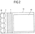
- FIG. 2 shows a plan view of the in the FIG. 1 shown first embodiment, wherein in the present case, the arrangement of the four ceramic gassing membranes on the bottom surface of the Begasungs concerneders 10 with respect to the arrangement of the first and second guide plate 1, 2 is illustrated.
- the four ceramic gassing membranes are arranged in parallel along the first short side wall within a distance of 0.1 m from said first short side wall.
- the diameter of each gassing membrane in the present case is 0.15 m, but may also deviate from these dimensions.
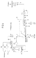
- FIG. 3 shows a further preferred embodiment of the present device. Unlike the ones in the FIGS. 1a, b In embodiments shown in which the flocculation unit 20 is arranged spatially separated from the container 10 (not shown) is in the in FIG. 3 illustrated embodiment, the flocculation unit 20 integrated into the container 10.
- a flocculation space or section 20 of the container 10 is provided, in which the water to be purified and the flocculant are introduced.
- the mixture can be introduced in the upper region of the flocculation 20 via a partition in another separate from the actual flotation cell section 21, in which a further Flockulationscouskar can be added.
- the partition wall provided between the flocculation section 20 and the section 21 for supplying the further flocculation aids may have a height which is a carry of the flocculant added water from the flocculation section 20 into the section 21 allows.
- the water to be purified is passed from top to bottom in section 21 and can subsequently enter the contact zone K of the container 10 at the bottom of the container and be passed via the gassing unit 30. Accordingly, the water to be purified in the embodiment of the FIG. 3 meandering from the flocculation section 20 into the section 21 and finally into the contact zone K of the flotation cell or container 10 introduced.
- the present experimental procedure uses waste water that has been treated with humic substances.
- Humic substances are complexly linked molecular chains of alkyl and aromatic moieties having functional groups such as -COOH, -NH 2 and -RSH. Due to the ionized acid groups, they form negatively charged macromolecules.
- humic substances contained in the water are especially trivalent ions containing iron and aluminum-containing substances as precipitants, which may be liquid or solid.
- solid FeCl 3 is used to prepare a liquid precipitant.
- the dirty water is mixed with the solution containing humic acids and then mixed with the FeCl 3 -containing solution using a static mixer in Flockulationstank 20.
- Flocculation tank 20 flocculates the humic acids contained in the dirty water by the flocculant FeCl 3 .
- the treated with FeCl 3 wastewater is then introduced in the present experimental method then from the Flockulationstank 20 in the Trennungs actuallyer- or Begasungs actuallyer 10 with a flow rate of 400 liters per hour.
- the introduction into the container 10 takes place in a region between the first short Side wall of the container 10 and the second baffle 2, that is in an area in front of the second baffle 2. This can be done from above the open side of the container 10 or laterally down into the container 10.
- the second baffle 2 is inclined at an angle ⁇ of, for example, 80 ° to the short side wall, so that it is due to the reduction of the gap width between the side wall and the second baffle to increase the flow velocity of the introduced flocculation in the direction of the bottom of the gassing vessel 10th arranged gassing membrane 30 comes.
- gassing unit 30 which in the present case consists of four individual gassing membranes, gas, in particular air, is injected, with the formation of microbubbles occurring directly in the introduced flocculation-added water.
- gas in particular air
- the thus formed flake-air bubble agglomerates are directed along the inclined first guide plate 1 in the direction of the surface of the liquid contained in the container 10 and thus into the separation zone S of the container 10.
- Bubbles that escape in the middle of the gas membrane have a smaller ascent rate than the outer ones because of the swarming nature of the bubble cloud.
- the bubbles escape relatively uniformly over the entire membrane surface. The larger the set gas pressure, the more and the bigger and faster the bubbles will be.
- the entrance velocity of the flocculation mixture into the contact zone K of the container 10 is of the same order of magnitude as the rate of bubble rise, so that the bubbles are not in the area of the passage gap on the left Pool edge can ascend.
- the microbubbles As a result of the attachment of the microbubbles to the flocculated organic constituents, they rise in the direction of the surface of the liquid present in the container 10 and form on the water surface a solid layer which is mechanically separated, for example using scraping devices such as scrapers. Below this solid layer, the purified water is in the separation zone S of the container 10. The thus prepurified water is withdrawn using a pump E1 through the submerged filtration unit 40 and is available as purified water for further processing, such as other desalination processes available.
- air can be passed directly to the surface of the filtration unit 40 via apertured tubing, thereby causing mechanical removal of deposits on the surface of the filtration unit 40.
Applications Claiming Priority (2)
| Application Number | Priority Date | Filing Date | Title |
|---|---|---|---|
| DE201210207731 DE102012207731A1 (de) | 2012-05-09 | 2012-05-09 | Vorrichtung und Verfahren zur Vorreinigung von Wasser,insbesondere Meerwasser |
| PCT/EP2013/058079 WO2013167358A1 (de) | 2012-05-09 | 2013-04-18 | Vorrichtung und verfahren zur wasserreinigung mit flotation |
Publications (2)
| Publication Number | Publication Date |
|---|---|
| EP2867174A1 EP2867174A1 (de) | 2015-05-06 |
| EP2867174B1 true EP2867174B1 (de) | 2016-09-07 |
Family
ID=48430669
Family Applications (1)
| Application Number | Title | Priority Date | Filing Date |
|---|---|---|---|
| EP13722305.3A Active EP2867174B1 (de) | 2012-05-09 | 2013-04-18 | Vorrichtung und verfahren zur wasserreinigung mit flotation |
Country Status (15)
| Country | Link |
|---|---|
| US (1) | US10029925B2 (ru) |
| EP (1) | EP2867174B1 (ru) |
| AU (1) | AU2013258354B2 (ru) |
| BR (1) | BR112014027304B1 (ru) |
| CA (1) | CA2871966C (ru) |
| DE (1) | DE102012207731A1 (ru) |
| DK (1) | DK2867174T3 (ru) |
| ES (1) | ES2599820T3 (ru) |
| IN (1) | IN2014MN02465A (ru) |
| MX (1) | MX358898B (ru) |
| NO (1) | NO346436B1 (ru) |
| PL (1) | PL2867174T3 (ru) |
| PT (1) | PT2867174T (ru) |
| RU (1) | RU2630541C2 (ru) |
| WO (1) | WO2013167358A1 (ru) |
Families Citing this family (10)
| Publication number | Priority date | Publication date | Assignee | Title |
|---|---|---|---|---|
| CN113244774A (zh) | 2014-10-22 | 2021-08-13 | 科氏分离技术解决方案公司 | 使用膜束封罩和脉冲曝气的膜组件系统以及操作方法 |
| DE102015208694A1 (de) | 2015-05-11 | 2016-11-17 | Akvolution Gmbh | Vorrichtung und Verfahren zum Erzeugen von Gasblasen in einer Flüssigkeit |
| USD779632S1 (en) | 2015-08-10 | 2017-02-21 | Koch Membrane Systems, Inc. | Bundle body |
| TWI606884B (zh) * | 2016-01-29 | 2017-12-01 | 慶鴻機電工業股份有限公司 | 金屬加工機之回收液處理設備及其方法 |
| CN106673136A (zh) * | 2016-12-21 | 2017-05-17 | 安徽金川活动坝科技有限公司 | 基于平板陶瓷膜的双膜法废水装置 |
| PL238499B1 (pl) | 2017-12-31 | 2021-08-30 | King Abdulaziz City Sci & Tech | Układ oczyszczania wody i sposób czyszczenia membran filtracyjnych |
| DE102018101895B3 (de) | 2018-01-29 | 2019-02-07 | Akvola Technologies GmbH | Vorrichtung und Verfahren zum Erzeugen von Gasblasen in einer Flüssigkeit |
| DE102018128600B4 (de) * | 2018-11-14 | 2023-10-05 | Dawid Marek Slomski | Filtervorrichtung und Reinigungsanlage |
| IT201900018404A1 (it) * | 2019-10-10 | 2021-04-10 | De Nora Water Tech Italy S R L | Wastewater treatment apparatus |
| US11939233B2 (en) | 2021-12-10 | 2024-03-26 | Saudi Arabian Oil Company | Oil-water separation system using hydrophobic/hydrophilic materials for capacity increase and improving produced water quality |
Citations (2)
| Publication number | Priority date | Publication date | Assignee | Title |
|---|---|---|---|---|
| CA2527525A1 (en) * | 2005-11-17 | 2007-05-17 | Hydroxyl Systems Inc. | Wastewater treatment system for a marine vessel |
| WO2011026758A1 (en) * | 2009-09-02 | 2011-03-10 | Evonik Degussa Gmbh | Method for purifying water flowing in a river or canal |
Family Cites Families (18)
| Publication number | Priority date | Publication date | Assignee | Title |
|---|---|---|---|---|
| SE302103B (ru) * | 1964-12-05 | 1968-07-01 | Purac Ab | |
| FI83864C (fi) * | 1987-03-25 | 1991-09-10 | Oiva Suutarinen | Foerfarande foer renande av en vaetska fraon fasta och upploesta foeroreningar med ett flotationsklarning-flockningsfoerfarande. |
| FI86293C (fi) * | 1989-04-28 | 1992-08-10 | Oiva Suutarinen | Foerfarande foer rening av en vaetska fraon fasta och upploesta foeroreningar medelst ett flotationsfiltreringsfoerfarande. |
| SE503894C2 (sv) * | 1995-01-19 | 1996-09-30 | Norrtaelje Kommun | Anordning för distribution och dispersion av luftmättat vatten |
| JPH10109091A (ja) * | 1996-10-04 | 1998-04-28 | Chlorine Eng Corp Ltd | 水の処理方法 |
| DE19647512A1 (de) * | 1996-11-16 | 1998-05-20 | Damann Franz Josef | Mobile Klärvorrichtung |
| SE9700100L (sv) * | 1997-01-15 | 1998-07-16 | Vbb Viak Ab | Förfarande och anordning för avhärdning av vätska |
| DE10118940A1 (de) * | 2001-04-18 | 2002-10-24 | Georgi Joachim | Verfahren und Vorrichtung zur Erzeugung von feststoff- und mikroorganismenfreiem Trink- und Brauchwasser aus Frisch- oder Abwasser |
| US20040217058A1 (en) * | 2002-12-19 | 2004-11-04 | Jason Cadera | Integrated dissolved air flotation and immersed membrane filtration apparatus and method for using same |
| FR2890651B1 (fr) * | 2005-09-09 | 2007-11-09 | Degremont Sa | Appareil de clarification des eaux et procede de mise en oeuvre. |
| FR2891540B1 (fr) * | 2005-09-30 | 2007-12-28 | Otv Sa | Procede de traitement d'eaux comprenant une etape de decantation rapide suivie d'une etape de filtration directement sur membranes de micro ou d'ultra-filtration, et dispositif correspondant. |
| KR100759834B1 (ko) * | 2006-07-26 | 2007-10-04 | 한국과학기술연구원 | 미세기포 발생용 실리카 또는 알루미나 세라믹 멤브레인산기관, 그의 제조방법 및 제조장치 |
| DE102007007894A1 (de) * | 2007-02-14 | 2008-08-21 | Technische Universität Berlin | Verfahren zur Wiederherstellung optimaler Durchströmungseigenschaften von Membranfiltern |
| AT505282B1 (de) | 2007-10-03 | 2008-12-15 | Va Tech Wabag Gmbh | Verfahren und vorrichtung zur verminderung von biofouling an membranen druckgetriebener membrantrennverfahren |
| EP2234928A4 (en) * | 2007-12-19 | 2013-09-25 | Saudi Arabian Oil Co | BIOLOGICAL MEMBRANE REACTOR SYSTEM WITH ACTIVATED CARBON GRANULATE AS A TISSUE AND METHOD |
| BRPI0802065A2 (pt) * | 2008-05-09 | 2010-01-12 | Dt Engenharia De Empreendimentos Ltda | sistema modular de fluxo variável e contìnuo para tratamento de cursos d'água |
| EP2690070B1 (en) * | 2011-03-25 | 2016-12-14 | Doosan Heavy Industries & Construction Co., Ltd. | Dissolved-air flotation-type pretreatment apparatus |
| FR2995603B1 (fr) * | 2012-09-19 | 2014-09-26 | Veolia Water Solutions & Tech | Procede de traitement d’eau comprenant une flottation combinee a une filtration gravitaire et installation correspondante |
-
2012
- 2012-05-09 DE DE201210207731 patent/DE102012207731A1/de not_active Withdrawn
-
2013
- 2013-04-18 IN IN2465MUN2014 patent/IN2014MN02465A/en unknown
- 2013-04-18 US US14/397,556 patent/US10029925B2/en active Active
- 2013-04-18 WO PCT/EP2013/058079 patent/WO2013167358A1/de active Application Filing
- 2013-04-18 DK DK13722305.3T patent/DK2867174T3/da active
- 2013-04-18 MX MX2014013400A patent/MX358898B/es active IP Right Grant
- 2013-04-18 PL PL13722305T patent/PL2867174T3/pl unknown
- 2013-04-18 RU RU2014143696A patent/RU2630541C2/ru active
- 2013-04-18 AU AU2013258354A patent/AU2013258354B2/en active Active
- 2013-04-18 ES ES13722305.3T patent/ES2599820T3/es active Active
- 2013-04-18 EP EP13722305.3A patent/EP2867174B1/de active Active
- 2013-04-18 PT PT137223053T patent/PT2867174T/pt unknown
- 2013-04-18 CA CA2871966A patent/CA2871966C/en active Active
- 2013-04-18 BR BR112014027304-9A patent/BR112014027304B1/pt active IP Right Grant
- 2013-04-18 NO NO20141184A patent/NO346436B1/no unknown
Patent Citations (2)
| Publication number | Priority date | Publication date | Assignee | Title |
|---|---|---|---|---|
| CA2527525A1 (en) * | 2005-11-17 | 2007-05-17 | Hydroxyl Systems Inc. | Wastewater treatment system for a marine vessel |
| WO2011026758A1 (en) * | 2009-09-02 | 2011-03-10 | Evonik Degussa Gmbh | Method for purifying water flowing in a river or canal |
Also Published As
| Publication number | Publication date |
|---|---|
| US20150114910A1 (en) | 2015-04-30 |
| DK2867174T3 (da) | 2017-01-02 |
| IN2014MN02465A (ru) | 2015-07-10 |
| RU2630541C2 (ru) | 2017-09-11 |
| MX358898B (es) | 2018-09-07 |
| MX2014013400A (es) | 2015-02-04 |
| EP2867174A1 (de) | 2015-05-06 |
| BR112014027304B1 (pt) | 2020-12-15 |
| WO2013167358A1 (de) | 2013-11-14 |
| AU2013258354A1 (en) | 2014-10-09 |
| DE102012207731A1 (de) | 2013-11-14 |
| PL2867174T3 (pl) | 2017-02-28 |
| ES2599820T3 (es) | 2017-02-03 |
| PT2867174T (pt) | 2016-12-15 |
| NO20141184A1 (no) | 2015-01-26 |
| BR112014027304A2 (pt) | 2017-06-27 |
| RU2014143696A (ru) | 2016-07-10 |
| AU2013258354B2 (en) | 2017-04-13 |
| US10029925B2 (en) | 2018-07-24 |
| CA2871966A1 (en) | 2013-11-14 |
| CA2871966C (en) | 2022-12-13 |
| NO346436B1 (no) | 2022-08-15 |
Similar Documents
| Publication | Publication Date | Title |
|---|---|---|
| EP2867174B1 (de) | Vorrichtung und verfahren zur wasserreinigung mit flotation | |
| DE60102563T2 (de) | Wasser- und abwasserbehandlungsverfahren zur entfernung von verunreinigungen | |
| DE2710373A1 (de) | Wirbelkoagulationsverfahren und -vorrichtung zum reinigen von abwasser | |
| DE112007001863T5 (de) | Verfahren und Gerät zur Behandlung von Wasser oder Abwasser oder dergleichen | |
| DE60308189T2 (de) | Abwasserbehandlung mittels fest-flüssigtrennung und gepulste elektrische felder | |
| EP0571744A1 (de) | Verfahren und Anordnung zur Aufbereitung von Abwassern, insbesondere in Flugzeugen | |
| EP3294442B1 (de) | Vorrichtung und verfahren zum erzeugen von gasblasen in einer flüssigkeit | |
| EP3233229B1 (de) | Gewerbewasseraufbereitungsverfahren | |
| DE102010043662B4 (de) | Brauereiabwasseraufbereitungsverfahren sowie Brauereiabwasseraufbereitungsvorrichtung | |
| DE112014001292T5 (de) | Verfahren zur Wasseraufbereitung vor der Umkehrosmose | |
| CH647741A5 (en) | Method and apparatus for electrochemical cleaning of effluent | |
| DE4302319C2 (de) | Verfahren und Anordnung zur Aufbereitung von Abwassern in Flugzeugen | |
| EP2447218B1 (de) | Verfahren zur Aufarbeitung von Minenwässern | |
| EP2920119A1 (de) | Reinigung von mit öl verschmutztem wasser und hierfür geeignete vorrichtung | |
| DE602004006550T2 (de) | Flockungsapparat | |
| EP3746213B1 (de) | Vorrichtung und verfahren zum erzeugen von gasblasen in einer flüssigkeit | |
| WO1990003332A1 (de) | Verfahren zum entsorgen verbrauchter öl-/wasseremulsionen | |
| DE102009056175B4 (de) | Verfahren und Vorrichtung zur Entfernung partikulärer und/oder gelöster Stoffe aus wässrigen Medien | |
| EP0082809B1 (de) | Verfahren zur kontinuierlichen Abscheidung von in einer verunreinigten Flüssigkeit enthaltenen Stoffen und Vorrichtung zur Durchführung des Verfahrens | |
| DE3312241C2 (ru) | ||
| CN212833134U (zh) | 一种废乳化液多级油水分离预处理装置 | |
| DE2150898C3 (de) | Anlage zum Abscheiden von Feststoffen aus Flüssigkeiten | |
| AT503422B1 (de) | Vorrichtung zur trinkwassererzeugung | |
| DE19848346C2 (de) | Flotationsverfahren zum Rückhalten von in Wasser suspendierten, Biomasse bildenden Mikroorganismen in einem Becken | |
| DE2907146A1 (de) | Verfahren und vorrichtung zur flotationsreinigung von fluessigkeiten |
Legal Events
| Date | Code | Title | Description |
|---|---|---|---|
| PUAI | Public reference made under article 153(3) epc to a published international application that has entered the european phase |
Free format text: ORIGINAL CODE: 0009012 |
|
| 17P | Request for examination filed |
Effective date: 20150325 |
|
| AK | Designated contracting states |
Kind code of ref document: A1 Designated state(s): AL AT BE BG CH CY CZ DE DK EE ES FI FR GB GR HR HU IE IS IT LI LT LU LV MC MK MT NL NO PL PT RO RS SE SI SK SM TR |
|
| AX | Request for extension of the european patent |
Extension state: BA ME |
|
| DAX | Request for extension of the european patent (deleted) | ||
| GRAP | Despatch of communication of intention to grant a patent |
Free format text: ORIGINAL CODE: EPIDOSNIGR1 |
|
| RIC1 | Information provided on ipc code assigned before grant |
Ipc: C02F 1/44 20060101ALI20160224BHEP Ipc: C02F 9/00 20060101AFI20160224BHEP Ipc: C02F 1/24 20060101ALI20160224BHEP Ipc: C02F 103/08 20060101ALN20160224BHEP Ipc: B01D 21/01 20060101ALI20160224BHEP Ipc: C02F 1/52 20060101ALN20160224BHEP Ipc: B01D 21/00 20060101ALI20160224BHEP Ipc: C02F 101/30 20060101ALN20160224BHEP |
|
| INTG | Intention to grant announced |
Effective date: 20160322 |
|
| RIN1 | Information on inventor provided before grant (corrected) |
Inventor name: BEERY, MATAN Inventor name: REPKE, JENS-UWE Inventor name: WOZNY, GUENTER |
|
| RIN1 | Information on inventor provided before grant (corrected) |
Inventor name: WOZNY, GUENTER Inventor name: BEERY, MATAN Inventor name: REPKE, JENS-UWE |
|
| GRAS | Grant fee paid |
Free format text: ORIGINAL CODE: EPIDOSNIGR3 |
|
| GRAA | (expected) grant |
Free format text: ORIGINAL CODE: 0009210 |
|
| AK | Designated contracting states |
Kind code of ref document: B1 Designated state(s): AL AT BE BG CH CY CZ DE DK EE ES FI FR GB GR HR HU IE IS IT LI LT LU LV MC MK MT NL NO PL PT RO RS SE SI SK SM TR |
|
| REG | Reference to a national code |
Ref country code: GB Ref legal event code: FG4D Free format text: NOT ENGLISH |
|
| REG | Reference to a national code |
Ref country code: CH Ref legal event code: EP |
|
| REG | Reference to a national code |
Ref country code: IE Ref legal event code: FG4D Free format text: LANGUAGE OF EP DOCUMENT: GERMAN |
|
| REG | Reference to a national code |
Ref country code: AT Ref legal event code: REF Ref document number: 826679 Country of ref document: AT Kind code of ref document: T Effective date: 20161015 |
|
| REG | Reference to a national code |
Ref country code: DE Ref legal event code: R096 Ref document number: 502013004365 Country of ref document: DE |
|
| REG | Reference to a national code |
Ref country code: SE Ref legal event code: TRGR |
|
| REG | Reference to a national code |
Ref country code: NL Ref legal event code: FP |
|
| REG | Reference to a national code |
Ref country code: PT Ref legal event code: SC4A Ref document number: 2867174 Country of ref document: PT Date of ref document: 20161215 Kind code of ref document: T Free format text: AVAILABILITY OF NATIONAL TRANSLATION Effective date: 20161129 |
|
| REG | Reference to a national code |
Ref country code: DK Ref legal event code: T3 Effective date: 20161227 |
|
| REG | Reference to a national code |
Ref country code: LT Ref legal event code: MG4D |
|
| PG25 | Lapsed in a contracting state [announced via postgrant information from national office to epo] |
Ref country code: FI Free format text: LAPSE BECAUSE OF FAILURE TO SUBMIT A TRANSLATION OF THE DESCRIPTION OR TO PAY THE FEE WITHIN THE PRESCRIBED TIME-LIMIT Effective date: 20160907 Ref country code: NO Free format text: LAPSE BECAUSE OF FAILURE TO SUBMIT A TRANSLATION OF THE DESCRIPTION OR TO PAY THE FEE WITHIN THE PRESCRIBED TIME-LIMIT Effective date: 20161207 Ref country code: LT Free format text: LAPSE BECAUSE OF FAILURE TO SUBMIT A TRANSLATION OF THE DESCRIPTION OR TO PAY THE FEE WITHIN THE PRESCRIBED TIME-LIMIT Effective date: 20160907 Ref country code: RS Free format text: LAPSE BECAUSE OF FAILURE TO SUBMIT A TRANSLATION OF THE DESCRIPTION OR TO PAY THE FEE WITHIN THE PRESCRIBED TIME-LIMIT Effective date: 20160907 Ref country code: HR Free format text: LAPSE BECAUSE OF FAILURE TO SUBMIT A TRANSLATION OF THE DESCRIPTION OR TO PAY THE FEE WITHIN THE PRESCRIBED TIME-LIMIT Effective date: 20160907 |
|
| REG | Reference to a national code |
Ref country code: ES Ref legal event code: FG2A Ref document number: 2599820 Country of ref document: ES Kind code of ref document: T3 Effective date: 20170203 |
|
| REG | Reference to a national code |
Ref country code: CH Ref legal event code: NV Representative=s name: SCHMAUDER AND PARTNER AG PATENT- UND MARKENANW, CH Ref country code: CH Ref legal event code: PK Free format text: BERICHTIGUNG INHABER |
|
| RAP2 | Party data changed (patent owner data changed or rights of a patent transferred) |
Owner name: AKVOLA TECHNOLOGIES GMBH |
|
| PG25 | Lapsed in a contracting state [announced via postgrant information from national office to epo] |
Ref country code: GR Free format text: LAPSE BECAUSE OF FAILURE TO SUBMIT A TRANSLATION OF THE DESCRIPTION OR TO PAY THE FEE WITHIN THE PRESCRIBED TIME-LIMIT Effective date: 20161208 Ref country code: LV Free format text: LAPSE BECAUSE OF FAILURE TO SUBMIT A TRANSLATION OF THE DESCRIPTION OR TO PAY THE FEE WITHIN THE PRESCRIBED TIME-LIMIT Effective date: 20160907 |
|
| REG | Reference to a national code |
Ref country code: FR Ref legal event code: PLFP Year of fee payment: 5 |
|
| PG25 | Lapsed in a contracting state [announced via postgrant information from national office to epo] |
Ref country code: EE Free format text: LAPSE BECAUSE OF FAILURE TO SUBMIT A TRANSLATION OF THE DESCRIPTION OR TO PAY THE FEE WITHIN THE PRESCRIBED TIME-LIMIT Effective date: 20160907 Ref country code: RO Free format text: LAPSE BECAUSE OF FAILURE TO SUBMIT A TRANSLATION OF THE DESCRIPTION OR TO PAY THE FEE WITHIN THE PRESCRIBED TIME-LIMIT Effective date: 20160907 |
|
| PG25 | Lapsed in a contracting state [announced via postgrant information from national office to epo] |
Ref country code: IS Free format text: LAPSE BECAUSE OF FAILURE TO SUBMIT A TRANSLATION OF THE DESCRIPTION OR TO PAY THE FEE WITHIN THE PRESCRIBED TIME-LIMIT Effective date: 20170107 Ref country code: SK Free format text: LAPSE BECAUSE OF FAILURE TO SUBMIT A TRANSLATION OF THE DESCRIPTION OR TO PAY THE FEE WITHIN THE PRESCRIBED TIME-LIMIT Effective date: 20160907 Ref country code: BG Free format text: LAPSE BECAUSE OF FAILURE TO SUBMIT A TRANSLATION OF THE DESCRIPTION OR TO PAY THE FEE WITHIN THE PRESCRIBED TIME-LIMIT Effective date: 20161207 Ref country code: SM Free format text: LAPSE BECAUSE OF FAILURE TO SUBMIT A TRANSLATION OF THE DESCRIPTION OR TO PAY THE FEE WITHIN THE PRESCRIBED TIME-LIMIT Effective date: 20160907 |
|
| REG | Reference to a national code |
Ref country code: DE Ref legal event code: R097 Ref document number: 502013004365 Country of ref document: DE |
|
| PLBE | No opposition filed within time limit |
Free format text: ORIGINAL CODE: 0009261 |
|
| STAA | Information on the status of an ep patent application or granted ep patent |
Free format text: STATUS: NO OPPOSITION FILED WITHIN TIME LIMIT |
|
| 26N | No opposition filed |
Effective date: 20170608 |
|
| PG25 | Lapsed in a contracting state [announced via postgrant information from national office to epo] |
Ref country code: SI Free format text: LAPSE BECAUSE OF FAILURE TO SUBMIT A TRANSLATION OF THE DESCRIPTION OR TO PAY THE FEE WITHIN THE PRESCRIBED TIME-LIMIT Effective date: 20160907 |
|
| REG | Reference to a national code |
Ref country code: IE Ref legal event code: MM4A |
|
| PG25 | Lapsed in a contracting state [announced via postgrant information from national office to epo] |
Ref country code: MC Free format text: LAPSE BECAUSE OF FAILURE TO SUBMIT A TRANSLATION OF THE DESCRIPTION OR TO PAY THE FEE WITHIN THE PRESCRIBED TIME-LIMIT Effective date: 20160907 |
|
| PG25 | Lapsed in a contracting state [announced via postgrant information from national office to epo] |
Ref country code: LU Free format text: LAPSE BECAUSE OF NON-PAYMENT OF DUE FEES Effective date: 20170418 |
|
| REG | Reference to a national code |
Ref country code: BE Ref legal event code: MM Effective date: 20170430 |
|
| REG | Reference to a national code |
Ref country code: FR Ref legal event code: PLFP Year of fee payment: 6 |
|
| PG25 | Lapsed in a contracting state [announced via postgrant information from national office to epo] |
Ref country code: IE Free format text: LAPSE BECAUSE OF NON-PAYMENT OF DUE FEES Effective date: 20170418 |
|
| PG25 | Lapsed in a contracting state [announced via postgrant information from national office to epo] |
Ref country code: BE Free format text: LAPSE BECAUSE OF NON-PAYMENT OF DUE FEES Effective date: 20170430 |
|
| PG25 | Lapsed in a contracting state [announced via postgrant information from national office to epo] |
Ref country code: MT Free format text: LAPSE BECAUSE OF FAILURE TO SUBMIT A TRANSLATION OF THE DESCRIPTION OR TO PAY THE FEE WITHIN THE PRESCRIBED TIME-LIMIT Effective date: 20160907 |
|
| PG25 | Lapsed in a contracting state [announced via postgrant information from national office to epo] |
Ref country code: AL Free format text: LAPSE BECAUSE OF FAILURE TO SUBMIT A TRANSLATION OF THE DESCRIPTION OR TO PAY THE FEE WITHIN THE PRESCRIBED TIME-LIMIT Effective date: 20160907 |
|
| PG25 | Lapsed in a contracting state [announced via postgrant information from national office to epo] |
Ref country code: HU Free format text: LAPSE BECAUSE OF FAILURE TO SUBMIT A TRANSLATION OF THE DESCRIPTION OR TO PAY THE FEE WITHIN THE PRESCRIBED TIME-LIMIT; INVALID AB INITIO Effective date: 20130418 |
|
| PG25 | Lapsed in a contracting state [announced via postgrant information from national office to epo] |
Ref country code: CY Free format text: LAPSE BECAUSE OF FAILURE TO SUBMIT A TRANSLATION OF THE DESCRIPTION OR TO PAY THE FEE WITHIN THE PRESCRIBED TIME-LIMIT Effective date: 20160907 |
|
| PG25 | Lapsed in a contracting state [announced via postgrant information from national office to epo] |
Ref country code: MK Free format text: LAPSE BECAUSE OF FAILURE TO SUBMIT A TRANSLATION OF THE DESCRIPTION OR TO PAY THE FEE WITHIN THE PRESCRIBED TIME-LIMIT Effective date: 20160907 |
|
| PGFP | Annual fee paid to national office [announced via postgrant information from national office to epo] |
Ref country code: NL Payment date: 20230417 Year of fee payment: 11 |
|
| PGFP | Annual fee paid to national office [announced via postgrant information from national office to epo] |
Ref country code: PT Payment date: 20230417 Year of fee payment: 11 Ref country code: IT Payment date: 20230428 Year of fee payment: 11 Ref country code: FR Payment date: 20230417 Year of fee payment: 11 Ref country code: ES Payment date: 20230517 Year of fee payment: 11 Ref country code: DK Payment date: 20230419 Year of fee payment: 11 Ref country code: DE Payment date: 20230412 Year of fee payment: 11 Ref country code: CZ Payment date: 20230405 Year of fee payment: 11 Ref country code: CH Payment date: 20230502 Year of fee payment: 11 |
|
| PGFP | Annual fee paid to national office [announced via postgrant information from national office to epo] |
Ref country code: TR Payment date: 20230414 Year of fee payment: 11 Ref country code: SE Payment date: 20230419 Year of fee payment: 11 Ref country code: PL Payment date: 20230404 Year of fee payment: 11 Ref country code: AT Payment date: 20230414 Year of fee payment: 11 |
|
| PGFP | Annual fee paid to national office [announced via postgrant information from national office to epo] |
Ref country code: GB Payment date: 20230420 Year of fee payment: 11 |