EP2865907A1 - Linear drive assembly - Google Patents
Linear drive assembly Download PDFInfo
- Publication number
- EP2865907A1 EP2865907A1 EP20130306472 EP13306472A EP2865907A1 EP 2865907 A1 EP2865907 A1 EP 2865907A1 EP 20130306472 EP20130306472 EP 20130306472 EP 13306472 A EP13306472 A EP 13306472A EP 2865907 A1 EP2865907 A1 EP 2865907A1
- Authority
- EP
- European Patent Office
- Prior art keywords
- longitudinal
- slider
- guide assembly
- linear motion
- motion guide
- Prior art date
- Legal status (The legal status is an assumption and is not a legal conclusion. Google has not performed a legal analysis and makes no representation as to the accuracy of the status listed.)
- Granted
Links
- 125000006850 spacer group Chemical group 0.000 claims description 9
- 238000005096 rolling process Methods 0.000 claims description 2
- 238000007789 sealing Methods 0.000 description 7
- 238000011109 contamination Methods 0.000 description 2
- 239000000428 dust Substances 0.000 description 2
- 230000007613 environmental effect Effects 0.000 description 2
- 238000003780 insertion Methods 0.000 description 2
- 230000037431 insertion Effects 0.000 description 2
- 239000002245 particle Substances 0.000 description 2
- 230000005540 biological transmission Effects 0.000 description 1
- 238000006243 chemical reaction Methods 0.000 description 1
- 230000008878 coupling Effects 0.000 description 1
- 238000010168 coupling process Methods 0.000 description 1
- 238000005859 coupling reaction Methods 0.000 description 1
- 230000000694 effects Effects 0.000 description 1
- 238000000605 extraction Methods 0.000 description 1
- 238000001125 extrusion Methods 0.000 description 1
- 239000000314 lubricant Substances 0.000 description 1
- 238000004519 manufacturing process Methods 0.000 description 1
- 230000000750 progressive effect Effects 0.000 description 1
- 230000000717 retained effect Effects 0.000 description 1
- 239000007787 solid Substances 0.000 description 1
Images

Classifications
-
- F—MECHANICAL ENGINEERING; LIGHTING; HEATING; WEAPONS; BLASTING
- F16—ENGINEERING ELEMENTS AND UNITS; GENERAL MEASURES FOR PRODUCING AND MAINTAINING EFFECTIVE FUNCTIONING OF MACHINES OR INSTALLATIONS; THERMAL INSULATION IN GENERAL
- F16C—SHAFTS; FLEXIBLE SHAFTS; ELEMENTS OR CRANKSHAFT MECHANISMS; ROTARY BODIES OTHER THAN GEARING ELEMENTS; BEARINGS
- F16C29/00—Bearings for parts moving only linearly
- F16C29/08—Arrangements for covering or protecting the ways
- F16C29/082—Arrangements for covering or protecting the ways fixed to the way
-
- F—MECHANICAL ENGINEERING; LIGHTING; HEATING; WEAPONS; BLASTING
- F16—ENGINEERING ELEMENTS AND UNITS; GENERAL MEASURES FOR PRODUCING AND MAINTAINING EFFECTIVE FUNCTIONING OF MACHINES OR INSTALLATIONS; THERMAL INSULATION IN GENERAL
- F16C—SHAFTS; FLEXIBLE SHAFTS; ELEMENTS OR CRANKSHAFT MECHANISMS; ROTARY BODIES OTHER THAN GEARING ELEMENTS; BEARINGS
- F16C41/00—Other accessories, e.g. devices integrated in the bearing not relating to the bearing function as such
- F16C41/007—Encoders, e.g. parts with a plurality of alternating magnetic poles
-
- F—MECHANICAL ENGINEERING; LIGHTING; HEATING; WEAPONS; BLASTING
- F16—ENGINEERING ELEMENTS AND UNITS; GENERAL MEASURES FOR PRODUCING AND MAINTAINING EFFECTIVE FUNCTIONING OF MACHINES OR INSTALLATIONS; THERMAL INSULATION IN GENERAL
- F16C—SHAFTS; FLEXIBLE SHAFTS; ELEMENTS OR CRANKSHAFT MECHANISMS; ROTARY BODIES OTHER THAN GEARING ELEMENTS; BEARINGS
- F16C35/00—Rigid support of bearing units; Housings, e.g. caps, covers
Definitions
- This invention relates to a linear drive assembly comprising a stationary tubular housing and a movable slider movable onto the tubular housing.
- US 4 512 208 A discloses a linear drive provided with a stiff elongated tubular housing formed with an axially extending slit.
- a drive spindle is retained within the tubular housing in bearings located in end flanges of the housing, driven for example by a motor.
- a slider is guided on the housing by interengaging slit and projection means and coupled to at least one spindle nut through the slit.
- the slit is closed by a flexible cover which is lifted out of the slit at one end of the slider and re-seated in the slit at the other end of the slider to form a completely enclosed housing in which the spindle and spindle nuts are protected from environmental contamination, and which can retain lubricant for high-efficiency, low-noise force transmission and conversion.
- the cover has two flexible longitudinal webs located to fit within the slit each on one side thereof. Each web is provided with one laterally protruding projection that is received in a corresponding lateral recess in the slit to provide a resilient snap fit between the flexible cover and the housing.
- This snap fit coupling between the cover and housing may, however become less than satisfactory over time, particularly in challenging operational conditions, e.g. in the presence of dust, or particles in the environment. In such cases, pollution may find its way between the webs and the side walls of the slit and penetrate the interior of the housing.
- a linear motion guide assembly comprising a tubular housing provided with a longitudinal internal cavity for accommodating a linear drive, a longitudinal slit between the longitudinal cavity and an outer face of the housing and a pair of longitudinal side grooves formed on the outer face of the housing on each side of the longitudinal slit, each of the side grooves having opposed concave side wall portions.
- a cover band covers the longitudinal slit and side grooves.
- the cover band is provided with a pair of longitudinal resilient protruding portions each arranged so as to be releasably engaged and clamped in a respective one of the side grooves of the housing.
- a slider slides or rolls on a longitudinal track of the housing between two end positions, the slider extending through the longitudinal slit to be coupled to the linear drive, the slider having two longitudinal ends and being provided with guiding means for lifting a portion of the cover band between the longitudinal ends of the slider on a path out of engagement with the side grooves.
- Each longitudinal resilient protruding portion comprises a pair of parallel ribs spaced apart from one another, each rib having a convex external face facing away from the other rib and an internal face facing the other rib.
- the side grooves are spaced apart from the longitudinal slit, to improve the sealing properties of the cover. Thanks to the two parallel ribs in each groove, which are spaced apart from one another in the lateral direction, there is no continuous path at the interface between the ribs and the grooves for the pollution to migrate from the environment into the slit. Even if the external one of the two ribs were to be in contact with pollution, e.g. dust or solid particles, the internal rib in the same groove would remain free from such pollution.
- pollution e.g. dust or solid particles
- each rib has its own flexibility, it becomes possible to satisfy two apparently conflicting requirements, namely a reduced insertion force on the one hand and an important contact surface between the sealing ribs and the side wall of the groove and/or an important contact pressure on the other hand.
- each of the side grooves has a narrow portion opening into a wider internal cavity. Once the ribs have passed the narrow portion, they can expand into the cavity and provide the desired snap fit.
- each of the side grooves has a tapered entry portion converging towards the narrow portion. The tapered entry guides the ribs towards the narrow portion and contributes to their progressive deformation, which is necessary for them to pass through the narrow portion, which forms a bottleneck.
- each longitudinal resilient protruding portion has a maximum width measured between the convex external faces of the parallel ribs, which is wider than the intermediate narrow section of the respective side groove. This provides the desired snap fit effect once the ribs have entered the associated groove.
- each longitudinal resilient protruding portion has distal ends which, in cross-section, converge towards one another. These converging portions contribute to guiding each longitudinal resilient protruding portion upon entry into the associated groove. These converging portions are even more effective when combined with a tapered entry into the groove, as mentioned earlier.
- the convex faces of the two ribs of each longitudinal resilient protruding portion have proximal ends, which, in cross-section, converge towards one another.
- the proximal end or reduced width seats in the corresponding portion of reduced width of the associated groove.
- the ribs have flexible proximal end. Hence, each rib is able to pivot about its proximal end during the insertion and extraction phases.
- the internal faces are concave faces.
- the concave internal faces of the two ribs of each longitudinal resilient protruding portion form a cavity.
- a cavity is a discontinuity of the interface between the longitudinal resilient protruding portion and the associated groove.
- a resilient spacer can be inserted and clamped in the cavity. This resilient spacer, which can be e.g. a cylindrical spacer, modifies the flexibility of the each longitudinal resilient protruding portion.
- each side groove has a constant cross-section and each longitudinal resilient protruding portion has a constant cross-section, which simplifies the manufacturing process, e.g. by extrusion.
- a sensor is received in one of the side grooves and fixed relative to the housing such that at least when the slider is in a reading position the sensor faces at an air gap distance an encoder fixed to slider.
- the sensor is both protected by the cover and readily accessible, outside the longitudinal internal cavity of the tubular housing. This means in particular that the sensor can be provided as an optional feature of the linear motion guide assembly depending on the actual needs of the customer. It can also be retrofitted if necessary.
- the encoder can be a surface of the slider or a separate component, e.g. a magnetic encoder. The sensor and encoder can be used to detect a position or speed of the slider, or to provide an identification of a specific type of slider if different sliders are available for the same housing.
- the encoder extends over a substantial part of a length of the slider, such that when the slider is at any given position over the sensor, the sensor is at the air gap distance of the encoder.
- the senor is connected to an electronic circuit fixed relative to tubular housing.
- a linear motion guide assembly comprising:
- a sensor device comprising at least a first sensor part received in one of the side grooves and fixed relative to the housing and a second sensor part fixed relative to the slider such that at least when the slider is in a reading position the first and second sensor parts face each other at an air gap distance.
- the sensor is both protected by the cover and readily accessible, outside the longitudinal internal cavity of the tubular housing. This means in particular that the sensor can be provided as an optional feature of the linear motion guide assembly depending on the actual needs of the customer. It can also be retrofitted if necessary.
- one of the first and second sensor parts is an encoder and the other of the first and second sensor parts is a sensor head for reading the encoder.
- the encoder can be a magnetic encoder.
- the encoder is the first sensor part received in one of said grooves.
- the encoder can extend over a substantial part of the longitudinal slit and define a reading interval of the slider, such that when the slider is at any given position in the reading interval, the second sensor part is at the air gap distance of the encoder.
- the sensor head is preferably connected to an electronic circuit fixed relative to the slider.
- the encoder is the second sensor part fixed relative to the slider.
- the encoder can extend over a substantial part of a length of the slider, such that when the slider is at any given position over the sensor head, the sensor head is at the air gap distance of the encoder.
- the encoder can be a surface of the slider or a separate component, e.g. a magnetic encoder.
- the sensor and encoder can be used to detect a position or speed of the slider, or to provide an identification of a specific type of slider if different sliders are available for the same housing.
- the sensor head is preferably connected to an electronic circuit fixed relative to tubular housing.
- a linear motion guide assembly 10 comprises a tubular housing 12 provided with a longitudinal internal cavity 14 for accommodating a linear drive (not shown), such as a lead screw, a ball screw, an endless toothed belt or an endless rope.
- a linear drive such as a lead screw, a ball screw, an endless toothed belt or an endless rope.
- a longitudinal slit 16 is provided between the longitudinal cavity 14 and an outer face 18 of the housing.
- a slider 20 slides or rolls on a longitudinal track of the housing, preferably a track formed on the outer face 18.
- the slider 20 is coupled to a movable member of the linear drive, e.g. to a nut in the case of an a lead screw, through the longitudinal slit 16 so as to move linearly between two end positions defined by the linear drive.
- the slit 16 is closed by a flexible cover band 22, which is lifted out of the slit 16 at one end of the slider 20 and re-seated in the slit 16 at the other end of the slider to form a completely enclosed housing protected from environmental contamination.
- a cover 20A of the slider 20 has been removed to reveal the path of the flexible cover band 22.
- a pair of longitudinal side grooves 24 is formed on the outer face 18 of the housing on each side of the central longitudinal slit 16.
- the cover band 22 comprises a pair of longitudinal resilient protruding portions 28 each arranged so as to be releasably engaged and clamped in a respective one of the pair of side grooves 24 of the housing.
- the two longitudinal ends of the slider 20 are each provided with two pairs of rollers 30, 32 for lifting a portion of the cover band between the longitudinal ends of the slider on a path out of engagement with the side grooves 24.
- the side grooves 24 and longitudinal resilient protruding portions 28 have constant cross-sections.
- Each longitudinal resilient protruding portion 28 comprises a pair of parallel ribs 34 spaced apart from one another, each rib having a convex external face 36 facing away from the other rib and a concave internal face 38 facing the other rib.
- Each of the side grooves 34 has a tapered entry portion 40 converging towards a narrow portion 42 followed by a wider internal cavity 43 with opposed concave side wall portions 44.
- Each longitudinal resilient protruding portion 28 has a maximum width W measured between the convex faces 36 of the parallel ribs 34, which is wider than the intermediate narrow portion 42 of the respective side groove 34, a preferably slightly wider, in a non-deformed state, than the width between the concave side wall portions 44, to ensure a surface of contact between the ribs 34 and concave side wall portions 44.
- the two ribs 34 of each longitudinal resilient protruding portion 28 have distal ends 46 that converge towards one another and proximal ends 48 that converge towards one another to form a flexible pivot.
- the concave internal faces 38 of the two ribs 34 of each longitudinal resilient protruding portion 28 form a cavity 50 in which a resilient spacer 52 can be inserted and clamped.
- the spacer 52 illustrated in Fig. 8 , has preferably a cylindrical shape and can be tubular or not.
- the spacer 50 in contact with the concave internal faces 38 of the two ribs 34, increases the stiffness of the longitudinal resilient protruding portion 28 and the contact pressure between the outer convex faces 36 of the ribs 34 and the side wall portions of the groove 24, and as a result increases the tightness of the sealing at the interface between the groove 24 and the longitudinal resilient protruding portion 28 of the cover 22.
- By changing the diameter or stiffness of the resilient spacer 50 different tightness coefficients can be obtained, with the same housing 12 and cover 20.
- a sensor head 54 illustrated in Fig. 9 can be received in one of the side grooves 24 and fixed relative to the housing 12 such that at least when the slider 20 is in a reading position the sensor faces at an air gap distance an encoder fixed to slider.
- the encoder preferably extends over a substantial part of a length of the slider 20, such that when the slider 20 is at any given position over the sensor head 54, the sensor head 54 is at the air gap distance of the encoder.
- the sensor head 54 is preferably connected to an electronic circuit fixed relative to tubular housing 12.
Abstract
Description
- This invention relates to a linear drive assembly comprising a stationary tubular housing and a movable slider movable onto the tubular housing.
-
US 4 512 208 A discloses a linear drive provided with a stiff elongated tubular housing formed with an axially extending slit. A drive spindle is retained within the tubular housing in bearings located in end flanges of the housing, driven for example by a motor. A slider is guided on the housing by interengaging slit and projection means and coupled to at least one spindle nut through the slit. The slit is closed by a flexible cover which is lifted out of the slit at one end of the slider and re-seated in the slit at the other end of the slider to form a completely enclosed housing in which the spindle and spindle nuts are protected from environmental contamination, and which can retain lubricant for high-efficiency, low-noise force transmission and conversion. The cover has two flexible longitudinal webs located to fit within the slit each on one side thereof. Each web is provided with one laterally protruding projection that is received in a corresponding lateral recess in the slit to provide a resilient snap fit between the flexible cover and the housing. - This snap fit coupling between the cover and housing may, however become less than satisfactory over time, particularly in challenging operational conditions, e.g. in the presence of dust, or particles in the environment. In such cases, pollution may find its way between the webs and the side walls of the slit and penetrate the interior of the housing.
- It has been suggested in
DE 43 34 311 - The foregoing shortcomings of the prior art are addressed by the present invention. According to one aspect of the invention, there is provided a linear motion guide assembly comprising a tubular housing provided with a longitudinal internal cavity for accommodating a linear drive, a longitudinal slit between the longitudinal cavity and an outer face of the housing and a pair of longitudinal side grooves formed on the outer face of the housing on each side of the longitudinal slit, each of the side grooves having opposed concave side wall portions. A cover band covers the longitudinal slit and side grooves. The cover band is provided with a pair of longitudinal resilient protruding portions each arranged so as to be releasably engaged and clamped in a respective one of the side grooves of the housing. A slider slides or rolls on a longitudinal track of the housing between two end positions, the slider extending through the longitudinal slit to be coupled to the linear drive, the slider having two longitudinal ends and being provided with guiding means for lifting a portion of the cover band between the longitudinal ends of the slider on a path out of engagement with the side grooves. Each longitudinal resilient protruding portion comprises a pair of parallel ribs spaced apart from one another, each rib having a convex external face facing away from the other rib and an internal face facing the other rib.
- The side grooves are spaced apart from the longitudinal slit, to improve the sealing properties of the cover. Thanks to the two parallel ribs in each groove, which are spaced apart from one another in the lateral direction, there is no continuous path at the interface between the ribs and the grooves for the pollution to migrate from the environment into the slit. Even if the external one of the two ribs were to be in contact with pollution, e.g. dust or solid particles, the internal rib in the same groove would remain free from such pollution.
- As each rib has its own flexibility, it becomes possible to satisfy two apparently conflicting requirements, namely a reduced insertion force on the one hand and an important contact surface between the sealing ribs and the side wall of the groove and/or an important contact pressure on the other hand.
- As will be explained in detail later on, it becomes also possible to increase the contact force without changing the whole cover, by inserting an additional resilient spacer sandwiched between the two ribs to reduce their flexion. Hence, the same housing and cover can easily adapted to a variety of environments.
- According to a preferred embodiment, each of the side grooves has a narrow portion opening into a wider internal cavity. Once the ribs have passed the narrow portion, they can expand into the cavity and provide the desired snap fit. Advantageously, each of the side grooves has a tapered entry portion converging towards the narrow portion. The tapered entry guides the ribs towards the narrow portion and contributes to their progressive deformation, which is necessary for them to pass through the narrow portion, which forms a bottleneck.
- Preferably each longitudinal resilient protruding portion has a maximum width measured between the convex external faces of the parallel ribs, which is wider than the intermediate narrow section of the respective side groove. This provides the desired snap fit effect once the ribs have entered the associated groove.
- According to a preferred embodiment, the two ribs of each longitudinal resilient protruding portion have distal ends which, in cross-section, converge towards one another. These converging portions contribute to guiding each longitudinal resilient protruding portion upon entry into the associated groove. These converging portions are even more effective when combined with a tapered entry into the groove, as mentioned earlier.
- According to a preferred embodiment, the convex faces of the two ribs of each longitudinal resilient protruding portion have proximal ends, which, in cross-section, converge towards one another. The proximal end or reduced width seats in the corresponding portion of reduced width of the associated groove.
- According to a preferred embodiment, the ribs have flexible proximal end. Hence, each rib is able to pivot about its proximal end during the insertion and extraction phases.
- According to a preferred embodiment, the internal faces are concave faces. Preferably the concave internal faces of the two ribs of each longitudinal resilient protruding portion form a cavity. As stated above, such a cavity is a discontinuity of the interface between the longitudinal resilient protruding portion and the associated groove. Moreover, a resilient spacer can be inserted and clamped in the cavity. This resilient spacer, which can be e.g. a cylindrical spacer, modifies the flexibility of the each longitudinal resilient protruding portion.
- Preferably, each side groove has a constant cross-section and each longitudinal resilient protruding portion has a constant cross-section, which simplifies the manufacturing process, e.g. by extrusion.
- According to a preferred embodiment, a sensor is received in one of the side grooves and fixed relative to the housing such that at least when the slider is in a reading position the sensor faces at an air gap distance an encoder fixed to slider. The sensor is both protected by the cover and readily accessible, outside the longitudinal internal cavity of the tubular housing. This means in particular that the sensor can be provided as an optional feature of the linear motion guide assembly depending on the actual needs of the customer. It can also be retrofitted if necessary. The encoder can be a surface of the slider or a separate component, e.g. a magnetic encoder. The sensor and encoder can be used to detect a position or speed of the slider, or to provide an identification of a specific type of slider if different sliders are available for the same housing.
- According to one embodiment, the encoder extends over a substantial part of a length of the slider, such that when the slider is at any given position over the sensor, the sensor is at the air gap distance of the encoder.
- Preferably the sensor is connected to an electronic circuit fixed relative to tubular housing.
- According to still another aspect of the invention, there is provided a linear motion guide assembly comprising:
- a tubular housing provided with a longitudinal internal cavity for accommodating a linear drive, a longitudinal slit between the longitudinal cavity and an outer face of the housing and a pair of longitudinal side grooves formed on the outer face of the housing on each side of the central slit, each of the side groove having opposed concave side wall portions;
- a cover band for covering the longitudinal slit and side grooves, the cover band being provided with a pair of longitudinal resilient protruding portions each arranged so as to be releasably engaged and clamped in a respective one of the pair of side grooves of the housing;
- a slider sliding or rolling on a longitudinal track of the housing between two end positions, the slider being coupled to the linear drive through the longitudinal slit, the slider having two longitudinal ends and being provided with guiding means for lifting a portion of the cover band between the longitudinal ends of the slider on a path out of engagement with the side grooves;
- characterised in that it further comprises a sensor device comprising at least a first sensor part received in one of the side grooves and fixed relative to the housing and a second sensor part fixed relative to the slider such that at least when the slider is in a reading position the first and second sensor parts face each other at an air gap distance. The sensor is both protected by the cover and readily accessible, outside the longitudinal internal cavity of the tubular housing. This means in particular that the sensor can be provided as an optional feature of the linear motion guide assembly depending on the actual needs of the customer. It can also be retrofitted if necessary.
- According to one embodiment, one of the first and second sensor parts is an encoder and the other of the first and second sensor parts is a sensor head for reading the encoder. In particular, the encoder can be a magnetic encoder.
- According to one embodiment, the encoder is the first sensor part received in one of said grooves. The encoder can extend over a substantial part of the longitudinal slit and define a reading interval of the slider, such that when the slider is at any given position in the reading interval, the second sensor part is at the air gap distance of the encoder. In this embodiment, the sensor head is preferably connected to an electronic circuit fixed relative to the slider.
- According to another embodiment, the encoder is the second sensor part fixed relative to the slider. In particular, the encoder can extend over a substantial part of a length of the slider, such that when the slider is at any given position over the sensor head, the sensor head is at the air gap distance of the encoder. The encoder can be a surface of the slider or a separate component, e.g. a magnetic encoder. The sensor and encoder can be used to detect a position or speed of the slider, or to provide an identification of a specific type of slider if different sliders are available for the same housing. In this embodiment, the sensor head is preferably connected to an electronic circuit fixed relative to tubular housing.
- Illustrative embodiments of the invention will now be described, purely by way of examples and without limitation to the scope of the claims, and with reference to the accompanying drawings, in which:
-
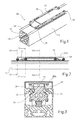
Fig. 1 is an isometric view of a linear motion guide assembly according to one embodiment of the invention; -
Fig. 2 is a schematic longitudinal section of the linear motion guide assembly ofFig. 1 . -
Fig. 3 is a simplified schematic cross-section of the linear motion guide assembly ofFig. 1 along the plane III-III ofFig. 2 ; -
Fig. 4 is a simplified schematic cross-section of the linear motion guide assembly ofFig. 1 along the plane IV-IV ofFig. 2 ; -
Fig. 5 is a simplified schematic cross-section of the linear motion guide assembly ofFig. 1 along the plane V-V ofFig. 2 ; -
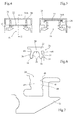
Fig. 6 is a detail of fromFig. 5 ; -
Fig. 7 is another detail fromFig.5 ; -
Fig. 8 is a detail of a variant of the assembly ofFig.1 ; -
Fig.9 is a detail of a variant of the assembly ofFig. 1 . - Corresponding reference numerals refer to the same or corresponding parts in each of the figures.
- Referring to
Figs. 1 to 7 , a linearmotion guide assembly 10 comprises atubular housing 12 provided with a longitudinalinternal cavity 14 for accommodating a linear drive (not shown), such as a lead screw, a ball screw, an endless toothed belt or an endless rope. Alongitudinal slit 16 is provided between thelongitudinal cavity 14 and anouter face 18 of the housing. - A
slider 20 slides or rolls on a longitudinal track of the housing, preferably a track formed on theouter face 18. Theslider 20 is coupled to a movable member of the linear drive, e.g. to a nut in the case of an a lead screw, through thelongitudinal slit 16 so as to move linearly between two end positions defined by the linear drive. Theslit 16 is closed by aflexible cover band 22, which is lifted out of theslit 16 at one end of theslider 20 and re-seated in theslit 16 at the other end of the slider to form a completely enclosed housing protected from environmental contamination. InFigure 1 , acover 20A of theslider 20 has been removed to reveal the path of theflexible cover band 22. A pair oflongitudinal side grooves 24 is formed on theouter face 18 of the housing on each side of the centrallongitudinal slit 16. Thecover band 22 comprises a pair of longitudinal resilient protrudingportions 28 each arranged so as to be releasably engaged and clamped in a respective one of the pair ofside grooves 24 of the housing. The two longitudinal ends of theslider 20 are each provided with two pairs ofrollers side grooves 24. Theside grooves 24 and longitudinal resilient protrudingportions 28 have constant cross-sections. - Each longitudinal resilient protruding
portion 28 comprises a pair ofparallel ribs 34 spaced apart from one another, each rib having a convexexternal face 36 facing away from the other rib and a concaveinternal face 38 facing the other rib. Each of theside grooves 34 has a taperedentry portion 40 converging towards anarrow portion 42 followed by a widerinternal cavity 43 with opposed concaveside wall portions 44. Each longitudinal resilient protrudingportion 28 has a maximum width W measured between the convex faces 36 of theparallel ribs 34, which is wider than the intermediatenarrow portion 42 of therespective side groove 34, a preferably slightly wider, in a non-deformed state, than the width between the concaveside wall portions 44, to ensure a surface of contact between theribs 34 and concaveside wall portions 44. In cross-section, the tworibs 34 of each longitudinal resilient protrudingportion 28 have distal ends 46 that converge towards one another and proximal ends 48 that converge towards one another to form a flexible pivot. - The concave
internal faces 38 of the tworibs 34 of each longitudinal resilient protrudingportion 28 form acavity 50 in which aresilient spacer 52 can be inserted and clamped. Thespacer 52, illustrated inFig. 8 , has preferably a cylindrical shape and can be tubular or not. When inserted in thecavity 50, thespacer 50, in contact with the concaveinternal faces 38 of the tworibs 34, increases the stiffness of the longitudinal resilient protrudingportion 28 and the contact pressure between the outer convex faces 36 of theribs 34 and the side wall portions of thegroove 24, and as a result increases the tightness of the sealing at the interface between thegroove 24 and the longitudinal resilient protrudingportion 28 of thecover 22. By changing the diameter or stiffness of theresilient spacer 50, different tightness coefficients can be obtained, with thesame housing 12 andcover 20. - A
sensor head 54, illustrated inFig. 9 can be received in one of theside grooves 24 and fixed relative to thehousing 12 such that at least when theslider 20 is in a reading position the sensor faces at an air gap distance an encoder fixed to slider. The encoder preferably extends over a substantial part of a length of theslider 20, such that when theslider 20 is at any given position over thesensor head 54, thesensor head 54 is at the air gap distance of the encoder. Thesensor head 54 is preferably connected to an electronic circuit fixed relative totubular housing 12. - While preferred embodiments of the invention have been described, it is to be understood by those skilled in the art that the invention is naturally not limited to these embodiments. Many variations are possible. The positions of the sensor head and encoder can be permuted. The internal cross-sections of the two grooves on each side of the longitudinal slit can be different, each associated to a different longitudinal resilient protruding portion with a corresponding shape.
Claims (15)
- A linear motion guide assembly (10) comprising:- a tubular housing (12) provided with a longitudinal internal cavity (14) for accommodating a linear drive, a longitudinal slit (16) between the longitudinal cavity (14) and an outer face (18) of the housing and a pair of longitudinal side grooves (24) formed on the outer face (18) of the housing on each side of the longitudinal slit (16), each of the side grooves (24) having opposed concave side wall portions (42);- a cover band (22) for covering the longitudinal slit (16) and side grooves (24), the cover band (22) being provided with a pair of longitudinal resilient protruding portions (28) each arranged so as to be releasably engaged and clamped in a respective one of the side grooves (24) of the housing;- a slider (20) sliding or rolling on a longitudinal track of the housing (20) between two end positions, the slider (20) extending through the longitudinal slit (16) to be coupled to the linear drive, the slider (20) having two longitudinal ends and being provided with guiding means (30, 32) for lifting a portion of the cover band (22) between the longitudinal ends of the slider (20) on a path out of engagement with the side grooves (24);
characterised in that each longitudinal resilient protruding portion (28) comprises a pair of parallel ribs (34) spaced apart from one another, each rib (34) having a convex external face (36) facing away from the other rib (34) and an internal face (38) facing the other rib (34). - The linear motion guide assembly of claim 1, characterised in that each of the side grooves (24) has a narrow portion (42) opening into a wider internal cavity (43).
- The linear motion guide assembly of claim 2, characterised in that each of the side grooves (24) has a tapered entry portion (40) converging towards the narrow portion (42).
- The linear motion guide assembly of claim 2 or claim 3, characterised in that each longitudinal resilient protruding portion (28) has a maximum width measured between the convex external faces (36) of the parallel ribs (34), which is wider than the intermediate narrow section (42) of the respective side groove (24).
- The linear motion guide assembly of any one of the preceding claims, characterised in that in cross-section the two ribs (34) of each longitudinal resilient protruding portion have distal ends (46) that converge towards one another.
- The linear motion guide assembly of any one of the preceding claims, characterised in that in cross-section the convex faces (36) of the two ribs of each longitudinal resilient protruding portion have proximal ends (48) that converge towards one another.
- The linear motion guide assembly of claim 6, characterised in that the ribs have flexible proximal end.
- The linear motion guide assembly of any one of the preceding claims, characterised in that the internal faces (38) are concave faces.
- The linear motion guide assembly of claim 8, characterised in that the concave internal faces (38) of the two ribs (34) of each longitudinal resilient protruding portion (28) form a cavity.
- The linear motion guide assembly of claim 9, further comprising a resilient spacer (52), inserted and clamped in the cavity.
- The linear motion guide assembly of any one of the preceding claims, characterised in that each side groove (24) has a constant cross-section.
- The linear motion guide assembly of any one of the preceding claims, characterised in that each longitudinal resilient protruding portion (28) has a constant cross-section.
- The linear motion guide assembly of any one of the preceding claims, characterised in that it further comprises a sensor (54) received in one of the side grooves and fixed relative to the housing such that at least when the slider is in a reading position the sensor (54) faces at an air gap distance an encoder fixed to slider.
- The linear motion guide assembly of claim 13, characterised in that the encoder extends over a substantial part of a length of the slider (20), such that when the slider (20) is at any given position over the sensor (54), the sensor (54) is at the air gap distance of the encoder.
- The linear motion guide assembly of any one of claims 13 or 14, characterised in that the sensor (54) is connected to an electronic circuit fixed relative to tubular housing.
Priority Applications (2)
| Application Number | Priority Date | Filing Date | Title |
|---|---|---|---|
| SI201330725T SI2865907T1 (en) | 2013-10-25 | 2013-10-25 | Linear drive assembly |
| EP13306472.5A EP2865907B1 (en) | 2013-10-25 | 2013-10-25 | Linear drive assembly |
Applications Claiming Priority (1)
| Application Number | Priority Date | Filing Date | Title |
|---|---|---|---|
| EP13306472.5A EP2865907B1 (en) | 2013-10-25 | 2013-10-25 | Linear drive assembly |
Publications (2)
| Publication Number | Publication Date |
|---|---|
| EP2865907A1 true EP2865907A1 (en) | 2015-04-29 |
| EP2865907B1 EP2865907B1 (en) | 2017-06-28 |
Family
ID=49578234
Family Applications (1)
| Application Number | Title | Priority Date | Filing Date |
|---|---|---|---|
| EP13306472.5A Active EP2865907B1 (en) | 2013-10-25 | 2013-10-25 | Linear drive assembly |
Country Status (2)
| Country | Link |
|---|---|
| EP (1) | EP2865907B1 (en) |
| SI (1) | SI2865907T1 (en) |
Citations (5)
| Publication number | Priority date | Publication date | Assignee | Title |
|---|---|---|---|---|
| US4512208A (en) * | 1982-02-13 | 1985-04-23 | Proma Produkt-Und Marketing Gesellschaft M.B.H. | Mechanical rotary-to-linear motion conversion element |
| DE4334311A1 (en) * | 1993-10-08 | 1995-04-13 | Schaeffler Waelzlager Kg | Protective cover for a track and a driving device for a linear guide |
| EP0790422A1 (en) * | 1996-02-14 | 1997-08-20 | Neff Antriebstechnik Automation GmbH | Guiding device with protective covering |
| US5842283A (en) * | 1995-08-11 | 1998-12-01 | Nippon Thompson Co., Ltd. | Position detection apparatus along with a track rail unit and guide unit on which it is equipped |
| DE19941587A1 (en) * | 1999-09-01 | 2001-03-08 | Schaeffler Waelzlager Ohg | Linear bearing with a device for measuring |
-
2013
- 2013-10-25 EP EP13306472.5A patent/EP2865907B1/en active Active
- 2013-10-25 SI SI201330725T patent/SI2865907T1/en unknown
Patent Citations (5)
| Publication number | Priority date | Publication date | Assignee | Title |
|---|---|---|---|---|
| US4512208A (en) * | 1982-02-13 | 1985-04-23 | Proma Produkt-Und Marketing Gesellschaft M.B.H. | Mechanical rotary-to-linear motion conversion element |
| DE4334311A1 (en) * | 1993-10-08 | 1995-04-13 | Schaeffler Waelzlager Kg | Protective cover for a track and a driving device for a linear guide |
| US5842283A (en) * | 1995-08-11 | 1998-12-01 | Nippon Thompson Co., Ltd. | Position detection apparatus along with a track rail unit and guide unit on which it is equipped |
| EP0790422A1 (en) * | 1996-02-14 | 1997-08-20 | Neff Antriebstechnik Automation GmbH | Guiding device with protective covering |
| DE19941587A1 (en) * | 1999-09-01 | 2001-03-08 | Schaeffler Waelzlager Ohg | Linear bearing with a device for measuring |
Also Published As
| Publication number | Publication date |
|---|---|
| EP2865907B1 (en) | 2017-06-28 |
| SI2865907T1 (en) | 2017-12-29 |
Similar Documents
| Publication | Publication Date | Title |
|---|---|---|
| US4512208A (en) | Mechanical rotary-to-linear motion conversion element | |
| JPH05164128A (en) | Direct driven type rolling guide unit | |
| WO2016152123A1 (en) | Linear motion guiding device | |
| JP5672895B2 (en) | Attachment for temporary shaft of linear motion guide device | |
| EP2865907B1 (en) | Linear drive assembly | |
| JP2010156381A (en) | Linear guide | |
| JPH0854018A (en) | Linear motion rolling guide unit | |
| JP4622971B2 (en) | Linear motion guide device | |
| US6935043B2 (en) | Scale device including means for preventing the occurence of small gaps between opposing walls of a guide opening | |
| JP5157439B2 (en) | Linear guide device | |
| JP5327015B2 (en) | Temporary shaft for linear motion guide device | |
| JP5772201B2 (en) | Linear motion guide device | |
| JP6129640B2 (en) | Dust-proof member and measuring instrument | |
| WO2022210059A1 (en) | Attachment for temporary shaft of linear motion guide device | |
| US9291482B2 (en) | Linear encoder | |
| JPH0649824U (en) | Linear motion rolling guide unit | |
| KR102324533B1 (en) | Ball Screw | |
| JP2012154431A (en) | Damage prevention component of linear guide device | |
| JP5059179B2 (en) | Exercise guidance device | |
| JP5545356B2 (en) | Linear guide device | |
| JP5803220B2 (en) | Linear motion guide device | |
| JP2009121648A (en) | Seal member protector for linear guide device and installation method of linear guide device using the protector | |
| JP2005201361A (en) | Linear guide device | |
| JP5807390B2 (en) | Temporary shaft of linear motion guide device | |
| WO2013088614A1 (en) | Side seal and linear motion guide device provided with same |
Legal Events
| Date | Code | Title | Description |
|---|---|---|---|
| PUAI | Public reference made under article 153(3) epc to a published international application that has entered the european phase |
Free format text: ORIGINAL CODE: 0009012 |
|
| 17P | Request for examination filed |
Effective date: 20141124 |
|
| AK | Designated contracting states |
Kind code of ref document: A1 Designated state(s): AL AT BE BG CH CY CZ DE DK EE ES FI FR GB GR HR HU IE IS IT LI LT LU LV MC MK MT NL NO PL PT RO RS SE SI SK SM TR |
|
| AX | Request for extension of the european patent |
Extension state: BA ME |
|
| RBV | Designated contracting states (corrected) |
Designated state(s): AL AT BE BG CH CY CZ DE DK EE ES FI FR GB GR HR HU IE IS IT LI LT LU LV MC MK MT NL NO PL PT RO RS SE SI SK SM TR |
|
| RIC1 | Information provided on ipc code assigned before grant |
Ipc: F16C 35/00 20060101ALN20161019BHEP Ipc: F16C 41/00 20060101ALI20161019BHEP Ipc: F16C 29/08 20060101AFI20161019BHEP |
|
| GRAP | Despatch of communication of intention to grant a patent |
Free format text: ORIGINAL CODE: EPIDOSNIGR1 |
|
| STAA | Information on the status of an ep patent application or granted ep patent |
Free format text: STATUS: GRANT OF PATENT IS INTENDED |
|
| INTG | Intention to grant announced |
Effective date: 20170103 |
|
| GRAS | Grant fee paid |
Free format text: ORIGINAL CODE: EPIDOSNIGR3 |
|
| GRAA | (expected) grant |
Free format text: ORIGINAL CODE: 0009210 |
|
| STAA | Information on the status of an ep patent application or granted ep patent |
Free format text: STATUS: THE PATENT HAS BEEN GRANTED |
|
| AK | Designated contracting states |
Kind code of ref document: B1 Designated state(s): AL AT BE BG CH CY CZ DE DK EE ES FI FR GB GR HR HU IE IS IT LI LT LU LV MC MK MT NL NO PL PT RO RS SE SI SK SM TR |
|
| REG | Reference to a national code |
Ref country code: GB Ref legal event code: FG4D |
|
| REG | Reference to a national code |
Ref country code: CH Ref legal event code: EP |
|
| REG | Reference to a national code |
Ref country code: AT Ref legal event code: REF Ref document number: 905137 Country of ref document: AT Kind code of ref document: T Effective date: 20170715 |
|
| REG | Reference to a national code |
Ref country code: IE Ref legal event code: FG4D |
|
| REG | Reference to a national code |
Ref country code: DE Ref legal event code: R096 Ref document number: 602013022798 Country of ref document: DE |
|
| PG25 | Lapsed in a contracting state [announced via postgrant information from national office to epo] |
Ref country code: NO Free format text: LAPSE BECAUSE OF FAILURE TO SUBMIT A TRANSLATION OF THE DESCRIPTION OR TO PAY THE FEE WITHIN THE PRESCRIBED TIME-LIMIT Effective date: 20170928 Ref country code: FI Free format text: LAPSE BECAUSE OF FAILURE TO SUBMIT A TRANSLATION OF THE DESCRIPTION OR TO PAY THE FEE WITHIN THE PRESCRIBED TIME-LIMIT Effective date: 20170628 Ref country code: GR Free format text: LAPSE BECAUSE OF FAILURE TO SUBMIT A TRANSLATION OF THE DESCRIPTION OR TO PAY THE FEE WITHIN THE PRESCRIBED TIME-LIMIT Effective date: 20170929 Ref country code: LT Free format text: LAPSE BECAUSE OF FAILURE TO SUBMIT A TRANSLATION OF THE DESCRIPTION OR TO PAY THE FEE WITHIN THE PRESCRIBED TIME-LIMIT Effective date: 20170628 Ref country code: HR Free format text: LAPSE BECAUSE OF FAILURE TO SUBMIT A TRANSLATION OF THE DESCRIPTION OR TO PAY THE FEE WITHIN THE PRESCRIBED TIME-LIMIT Effective date: 20170628 |
|
| REG | Reference to a national code |
Ref country code: NL Ref legal event code: MP Effective date: 20170628 |
|
| REG | Reference to a national code |
Ref country code: LT Ref legal event code: MG4D |
|
| REG | Reference to a national code |
Ref country code: AT Ref legal event code: MK05 Ref document number: 905137 Country of ref document: AT Kind code of ref document: T Effective date: 20170628 |
|
| PG25 | Lapsed in a contracting state [announced via postgrant information from national office to epo] |
Ref country code: NL Free format text: LAPSE BECAUSE OF FAILURE TO SUBMIT A TRANSLATION OF THE DESCRIPTION OR TO PAY THE FEE WITHIN THE PRESCRIBED TIME-LIMIT Effective date: 20170628 Ref country code: RS Free format text: LAPSE BECAUSE OF FAILURE TO SUBMIT A TRANSLATION OF THE DESCRIPTION OR TO PAY THE FEE WITHIN THE PRESCRIBED TIME-LIMIT Effective date: 20170628 Ref country code: SE Free format text: LAPSE BECAUSE OF FAILURE TO SUBMIT A TRANSLATION OF THE DESCRIPTION OR TO PAY THE FEE WITHIN THE PRESCRIBED TIME-LIMIT Effective date: 20170628 Ref country code: LV Free format text: LAPSE BECAUSE OF FAILURE TO SUBMIT A TRANSLATION OF THE DESCRIPTION OR TO PAY THE FEE WITHIN THE PRESCRIBED TIME-LIMIT Effective date: 20170628 Ref country code: BG Free format text: LAPSE BECAUSE OF FAILURE TO SUBMIT A TRANSLATION OF THE DESCRIPTION OR TO PAY THE FEE WITHIN THE PRESCRIBED TIME-LIMIT Effective date: 20170928 |
|
| PG25 | Lapsed in a contracting state [announced via postgrant information from national office to epo] |
Ref country code: EE Free format text: LAPSE BECAUSE OF FAILURE TO SUBMIT A TRANSLATION OF THE DESCRIPTION OR TO PAY THE FEE WITHIN THE PRESCRIBED TIME-LIMIT Effective date: 20170628 Ref country code: RO Free format text: LAPSE BECAUSE OF FAILURE TO SUBMIT A TRANSLATION OF THE DESCRIPTION OR TO PAY THE FEE WITHIN THE PRESCRIBED TIME-LIMIT Effective date: 20170628 Ref country code: AT Free format text: LAPSE BECAUSE OF FAILURE TO SUBMIT A TRANSLATION OF THE DESCRIPTION OR TO PAY THE FEE WITHIN THE PRESCRIBED TIME-LIMIT Effective date: 20170628 Ref country code: SK Free format text: LAPSE BECAUSE OF FAILURE TO SUBMIT A TRANSLATION OF THE DESCRIPTION OR TO PAY THE FEE WITHIN THE PRESCRIBED TIME-LIMIT Effective date: 20170628 Ref country code: CZ Free format text: LAPSE BECAUSE OF FAILURE TO SUBMIT A TRANSLATION OF THE DESCRIPTION OR TO PAY THE FEE WITHIN THE PRESCRIBED TIME-LIMIT Effective date: 20170628 |
|
| PG25 | Lapsed in a contracting state [announced via postgrant information from national office to epo] |
Ref country code: SM Free format text: LAPSE BECAUSE OF FAILURE TO SUBMIT A TRANSLATION OF THE DESCRIPTION OR TO PAY THE FEE WITHIN THE PRESCRIBED TIME-LIMIT Effective date: 20170628 Ref country code: PL Free format text: LAPSE BECAUSE OF FAILURE TO SUBMIT A TRANSLATION OF THE DESCRIPTION OR TO PAY THE FEE WITHIN THE PRESCRIBED TIME-LIMIT Effective date: 20170628 Ref country code: IS Free format text: LAPSE BECAUSE OF FAILURE TO SUBMIT A TRANSLATION OF THE DESCRIPTION OR TO PAY THE FEE WITHIN THE PRESCRIBED TIME-LIMIT Effective date: 20171028 Ref country code: ES Free format text: LAPSE BECAUSE OF FAILURE TO SUBMIT A TRANSLATION OF THE DESCRIPTION OR TO PAY THE FEE WITHIN THE PRESCRIBED TIME-LIMIT Effective date: 20170628 |
|
| REG | Reference to a national code |
Ref country code: DE Ref legal event code: R097 Ref document number: 602013022798 Country of ref document: DE |
|
| PG25 | Lapsed in a contracting state [announced via postgrant information from national office to epo] |
Ref country code: DK Free format text: LAPSE BECAUSE OF FAILURE TO SUBMIT A TRANSLATION OF THE DESCRIPTION OR TO PAY THE FEE WITHIN THE PRESCRIBED TIME-LIMIT Effective date: 20170628 |
|
| PLBE | No opposition filed within time limit |
Free format text: ORIGINAL CODE: 0009261 |
|
| STAA | Information on the status of an ep patent application or granted ep patent |
Free format text: STATUS: NO OPPOSITION FILED WITHIN TIME LIMIT |
|
| PG25 | Lapsed in a contracting state [announced via postgrant information from national office to epo] |
Ref country code: MC Free format text: LAPSE BECAUSE OF FAILURE TO SUBMIT A TRANSLATION OF THE DESCRIPTION OR TO PAY THE FEE WITHIN THE PRESCRIBED TIME-LIMIT Effective date: 20170628 |
|
| REG | Reference to a national code |
Ref country code: CH Ref legal event code: PL |
|
| 26N | No opposition filed |
Effective date: 20180329 |
|
| GBPC | Gb: european patent ceased through non-payment of renewal fee |
Effective date: 20171025 |
|
| REG | Reference to a national code |
Ref country code: IE Ref legal event code: MM4A |
|
| REG | Reference to a national code |
Ref country code: FR Ref legal event code: ST Effective date: 20180629 |
|
| PG25 | Lapsed in a contracting state [announced via postgrant information from national office to epo] |
Ref country code: LI Free format text: LAPSE BECAUSE OF NON-PAYMENT OF DUE FEES Effective date: 20171031 Ref country code: LU Free format text: LAPSE BECAUSE OF NON-PAYMENT OF DUE FEES Effective date: 20171025 Ref country code: GB Free format text: LAPSE BECAUSE OF NON-PAYMENT OF DUE FEES Effective date: 20171025 Ref country code: CH Free format text: LAPSE BECAUSE OF NON-PAYMENT OF DUE FEES Effective date: 20171031 |
|
| REG | Reference to a national code |
Ref country code: BE Ref legal event code: MM Effective date: 20171031 |
|
| PG25 | Lapsed in a contracting state [announced via postgrant information from national office to epo] |
Ref country code: FR Free format text: LAPSE BECAUSE OF NON-PAYMENT OF DUE FEES Effective date: 20171031 Ref country code: BE Free format text: LAPSE BECAUSE OF NON-PAYMENT OF DUE FEES Effective date: 20171031 |
|
| PG25 | Lapsed in a contracting state [announced via postgrant information from national office to epo] |
Ref country code: MT Free format text: LAPSE BECAUSE OF NON-PAYMENT OF DUE FEES Effective date: 20171025 |
|
| PG25 | Lapsed in a contracting state [announced via postgrant information from national office to epo] |
Ref country code: IE Free format text: LAPSE BECAUSE OF NON-PAYMENT OF DUE FEES Effective date: 20171025 |
|
| PG25 | Lapsed in a contracting state [announced via postgrant information from national office to epo] |
Ref country code: HU Free format text: LAPSE BECAUSE OF FAILURE TO SUBMIT A TRANSLATION OF THE DESCRIPTION OR TO PAY THE FEE WITHIN THE PRESCRIBED TIME-LIMIT; INVALID AB INITIO Effective date: 20131025 |
|
| PG25 | Lapsed in a contracting state [announced via postgrant information from national office to epo] |
Ref country code: CY Free format text: LAPSE BECAUSE OF FAILURE TO SUBMIT A TRANSLATION OF THE DESCRIPTION OR TO PAY THE FEE WITHIN THE PRESCRIBED TIME-LIMIT Effective date: 20170628 |
|
| PG25 | Lapsed in a contracting state [announced via postgrant information from national office to epo] |
Ref country code: MK Free format text: LAPSE BECAUSE OF FAILURE TO SUBMIT A TRANSLATION OF THE DESCRIPTION OR TO PAY THE FEE WITHIN THE PRESCRIBED TIME-LIMIT Effective date: 20170628 |
|
| PG25 | Lapsed in a contracting state [announced via postgrant information from national office to epo] |
Ref country code: TR Free format text: LAPSE BECAUSE OF FAILURE TO SUBMIT A TRANSLATION OF THE DESCRIPTION OR TO PAY THE FEE WITHIN THE PRESCRIBED TIME-LIMIT Effective date: 20170628 |
|
| PG25 | Lapsed in a contracting state [announced via postgrant information from national office to epo] |
Ref country code: PT Free format text: LAPSE BECAUSE OF FAILURE TO SUBMIT A TRANSLATION OF THE DESCRIPTION OR TO PAY THE FEE WITHIN THE PRESCRIBED TIME-LIMIT Effective date: 20170628 |
|
| PG25 | Lapsed in a contracting state [announced via postgrant information from national office to epo] |
Ref country code: AL Free format text: LAPSE BECAUSE OF FAILURE TO SUBMIT A TRANSLATION OF THE DESCRIPTION OR TO PAY THE FEE WITHIN THE PRESCRIBED TIME-LIMIT Effective date: 20170628 |
|
| STAA | Information on the status of an ep patent application or granted ep patent |
Free format text: STATUS: NO OPPOSITION FILED WITHIN TIME LIMIT |
|
| PGFP | Annual fee paid to national office [announced via postgrant information from national office to epo] |
Ref country code: SI Payment date: 20231012 Year of fee payment: 11 Ref country code: IT Payment date: 20231026 Year of fee payment: 11 Ref country code: DE Payment date: 20231020 Year of fee payment: 11 |