EP2865625A1 - Method and device for producing a safety element - Google Patents
Method and device for producing a safety element Download PDFInfo
- Publication number
- EP2865625A1 EP2865625A1 EP20140003565 EP14003565A EP2865625A1 EP 2865625 A1 EP2865625 A1 EP 2865625A1 EP 20140003565 EP20140003565 EP 20140003565 EP 14003565 A EP14003565 A EP 14003565A EP 2865625 A1 EP2865625 A1 EP 2865625A1
- Authority
- EP
- European Patent Office
- Prior art keywords
- web
- components
- security element
- draw roll
- lateral surface
- Prior art date
- Legal status (The legal status is an assumption and is not a legal conclusion. Google has not performed a legal analysis and makes no representation as to the accuracy of the status listed.)
- Granted
Links
Images


Classifications
-
- B—PERFORMING OPERATIONS; TRANSPORTING
- B42—BOOKBINDING; ALBUMS; FILES; SPECIAL PRINTED MATTER
- B42D—BOOKS; BOOK COVERS; LOOSE LEAVES; PRINTED MATTER CHARACTERISED BY IDENTIFICATION OR SECURITY FEATURES; PRINTED MATTER OF SPECIAL FORMAT OR STYLE NOT OTHERWISE PROVIDED FOR; DEVICES FOR USE THEREWITH AND NOT OTHERWISE PROVIDED FOR; MOVABLE-STRIP WRITING OR READING APPARATUS
- B42D25/00—Information-bearing cards or sheet-like structures characterised by identification or security features; Manufacture thereof
- B42D25/40—Manufacture
- B42D25/45—Associating two or more layers
-
- B—PERFORMING OPERATIONS; TRANSPORTING
- B42—BOOKBINDING; ALBUMS; FILES; SPECIAL PRINTED MATTER
- B42D—BOOKS; BOOK COVERS; LOOSE LEAVES; PRINTED MATTER CHARACTERISED BY IDENTIFICATION OR SECURITY FEATURES; PRINTED MATTER OF SPECIAL FORMAT OR STYLE NOT OTHERWISE PROVIDED FOR; DEVICES FOR USE THEREWITH AND NOT OTHERWISE PROVIDED FOR; MOVABLE-STRIP WRITING OR READING APPARATUS
- B42D25/00—Information-bearing cards or sheet-like structures characterised by identification or security features; Manufacture thereof
- B42D25/40—Manufacture
- B42D25/48—Controlling the manufacturing process
-
- B—PERFORMING OPERATIONS; TRANSPORTING
- B65—CONVEYING; PACKING; STORING; HANDLING THIN OR FILAMENTARY MATERIAL
- B65H—HANDLING THIN OR FILAMENTARY MATERIAL, e.g. SHEETS, WEBS, CABLES
- B65H23/00—Registering, tensioning, smoothing or guiding webs
- B65H23/02—Registering, tensioning, smoothing or guiding webs transversely
- B65H23/022—Registering, tensioning, smoothing or guiding webs transversely by tentering devices
- B65H23/025—Registering, tensioning, smoothing or guiding webs transversely by tentering devices by rollers
- B65H23/0258—Registering, tensioning, smoothing or guiding webs transversely by tentering devices by rollers with a bowed axis
Definitions
- the invention relates to a method for producing a security element for documents of value, banknotes or the like, comprising the steps of: providing a web which contains a plurality of first components of the security element for producing a plurality of the security element, and conveying the web along a route, and Applying a plurality of second components of the security element to the web at the end of the route.
- the invention further relates to an apparatus for producing a security element for documents of value, bank notes or the like, comprising: a conveyor for conveying a web, which contains a plurality of first components of the security element, along a route and at the end to produce a plurality of the security element the path arranged applicator for applying a plurality of second components of the security element on the web.
- security elements are increasingly used that consist of several constituents, for example of several layers.
- An example of such a security element are so-called moire magnifiers, in which microstructures and microlenses are applied one above the other.
- the microstructures lie on a substrate in a well-defined grid and the microlenses must be formed with respect to raster width and position of this defined grid in a precisely prescribed arrangement to the microstructures.
- the register between these two components must be followed very closely. This is technically complex, both when the first and second components are formed on different webs that need to be joined together, as well as when the first and second components are produced by successive printing and / or embossing processes.
- the application of the second components in exact register position or at least under exact compliance with the desired length ratios to the first components that are already present on the track, done.
- the generic WO 2009/083149 A2 deals with this problem area. It provides for the promotion of a web prior to the application of the second components before the use of a so-called Einschwenkwalze, which is made depending on the adjustment obliquely to the conveying direction of the web. In this way, the web is tilted with respect to the axis of a subsequent printing or embossing cylinder to the register layer between the first constituents that are already present on the web, and the second components to be applied with the printing or embossing cylinder through the cylinder jacket surface of the corresponding cylinder are set to adjust.
- the principle of WO 2009/083149 A2 has proved its worth.
- security elements which are further improved in terms of their security against counterfeiting, have further increased the requirements for register accuracy between the first and second components.
- material mixtures are increasingly used for security elements, that is, for example, the combination of a plastic web, which carries the plurality of first components of the security element, with a paper web, which provides the plurality of second components.
- These material mixtures Manufacturing technology are difficult to control due to different thermal expansions, warming when conveying a web, etc., as regards the register accuracy when bringing together the different materials.
- the invention is therefore based on the object, a method and an apparatus of the type mentioned in such a way that the register accuracy between the existing on the web first components and the application of the second components can be set as accurately as possible.
- a draw roll which has a two-dimensionally curved lateral surface.
- This draw roll makes it possible to adjust the tension or tension in the middle of the web with respect to the edges, for example to reduce (or preferential) or to increase the tension in the middle of the web.
- the tension conditions in the web can be adjusted so that the application of the plurality of second components of the security element in the register to the first components happening on the track.
- the web can be further processed, ie the end of the route is usually not the end of the processing plant.
- a biaxial curvature is understood to mean that the lateral surface in each case has a curvature in two sectional planes which are not parallel to one another, ie may be orthogonal in particular.
- the concept of biaxial curvature is therefore identical in the underlying understanding with the concept of a two-dimensionally curved surface in the mathematical sense.
- the curvature in each section plane is not limited to satisfying a circular geometry. Rather, arbitrarily shaped lateral surfaces also fall under the term biaxial or two-dimensional curvature.
- the biaxially curved lateral surface of the draw roll causes the draw roll is no longer a pure circular cylinder in the mathematical sense.
- a cylindrical surface is known to be obtained when moving a closed trajectory (the so-called generator) along a straight line.
- Conventional rolls have as a generator a circle which is displaced along a straight line, they are circular cylinders.
- the draw roll also has a circle as a generator in preferred embodiments, which is now displaced not along a straight line, but along a curved trajectory.
- the circle as a generator is responsible for a uniaxial curvature, the curved trajectory, along which the circle is moved to generate the lateral surface, causes a further axis of curvature.
- the approach of the present invention when conveying the web in the processing machine, allows the tension on the web to be adjusted to compensate for distortions across the width of the web.
- the processing steps may include, for example, the generation of a desired overall motif in which a first print layer is applied to the web in a first processing step. This can be the provision of the web to be conveyed or in the device a processing device located before the start of the route.
- the print layer can be, for example, a motif grid for a moiré magnifier, a modulo mapper or a tilted image with or without magnification effect.
- the application of the second components may be, for example, the application of a microlens layer with a microlens grid, which has to stand in a predetermined relationship to the first motif grid in order to achieve a desired overall motif.
- the draw roll according to the invention makes it possible to compensate for distortions across the width of the web, ie transversely to the conveying direction. Disturbances of one of the two motif grids and disturbances of the overall motive are avoided.
- the order in which the first and second components are applied can be reversed.
- the solution of the invention achieves a particular economics benefit in that wider webs can be used which would otherwise be required for conventional manufacturing apparatus / methods due to distortions caused by, for example, the conventional Conveying devices and / or caused by inhomogeneities in the material of the web or could be made worse, would not be suitable.
- the device can at the beginning of the route a processing device, for. B. a printing unit, which generates the first components on the web.
- the incoming film already contains the first constituents. Then the film passes through a printing unit, in which a UV-curable medium (embossing lacquer) is applied. Subsequently, the web is conveyed to an embossing station, which generates the second components by embossing and UV irradiation. There, the elongation of the incoming film must be corrected so that the second components harmonize as desired with the first components in terms of position and dimension. Preferably, the correction takes place immediately before the embossing tool. Instead of a UV-curable medium and a thermoplastic medium or a thermoplastic deformable film can be used.
- a UV-curable medium and a thermoplastic medium or a thermoplastic deformable film can be used.
- the processing steps in particular the production of the first and second components, can take place both on one and the same side of the web, as well as on different sides.
- a positive side effect of the device according to the invention or of the method according to the invention is that the requirement for the film quality with regard to stretching at different tension or different voltages is markedly reduced. It is no longer absolutely necessary to use films which have a very homogeneous expansion behavior, but can even out a material-related inhomogeneous expansion in the case of film material which exhibits a comparatively inhomogeneous expansion behavior by suitably setting the draw roll.
- a particularly preferred design is a roller which has the shape of a curved circular cylinder. It is therefore a circular cylinder in and of itself cylindrical, the term "circular cylinder” being understood here in the mathematical sense. He describes a cylinder, which is obtained by moving a circle, which is the generator in the mathematical sense, along an axis. By bending this axis, the draw roll provided according to the invention with a two-dimensionally curved lateral surface is obtained.
- the bending of the circular cylindrical roller that is, the deflection of the axis of the roller adjustable.
- the curved roller is additionally rotatably mounted at both ends such that the plane of the maximum bending can be inclined relative to the plane of the continuous film web (pivotable roller).
- the curved roller is additionally rotatably mounted at both ends such that the plane of the maximum bending can be inclined relative to the plane of the continuous film web (pivotable roller).
- the application of the plurality of second constituents of the security element can in a first embodiment be carried out by providing an additional web containing the plurality of second constituents and connecting it to the web.
- the invention is particularly advantageous in cases where the additional web is made of a different material than the web. For example, different strains of the material mix plastic web / paper web can be well balanced.
- an application device is provided which has a laminating unit, and a supply device feeds the additional path to the laminating unit.
- the plurality of second constituents are applied by means of a printing or embossing process. The device then has as an applicator on a printing or embossing. In the manufacturing process, the plurality of second components is applied at the end of the route through a printing or embossing cylinder, through which the web is guided.
- a further variant for the roller with a two-dimensionally curved lateral surface is a so-called S-roll: it contains in its interior a plurality of elements with the aid of which the extent of the sheathing at the respective point can be influenced. It has the advantage that the shape of the roller can be made very flexible, in particular can be more complicated than a simple bend.
- a curved circular cylinder whose bending and optionally also pivoting position are adjustable
- a cylinder which has a convex or concave shape in cross-section, ie is barrel-shaped or spindle-shaped.
- the curvature of the lateral surface is not changeable, but one can use a cylinder whose basic shape is adapted to normal conditions with respect to the stretching of the web.
- Alternative lateral surfaces are represented by cones in the middle or else considerably more complicated shapes, which can be realized by milling or turning and which influence the expansion of the film or the conveyed medium in the desired manner.
- rollers are not continuously deformed during operation, ie during rotation. The danger of a Material fatigue is lower or simpler materials for the roller can be used.
- the roller used has a sheath which influences the adhesion or friction to the medium used. Local adhesion or frictional properties varying over the length of the roll can also affect the elongation of the conveyed medium in the desired sense. With a positive result, a grooving of a plastic coating of a draw roll was tested.
- An alternative to producing a variable adhesion profile is to use a locally applicable electrostatic charge on the roller.
- the registration between first and second components is continuously monitored during operation and the position of the draw roller is adjusted accordingly within the scope of a regulation.
- the monitoring can be done after the application of the plurality of second components of the security element.
- This measurement can be carried out particularly simply, but has the disadvantage that errors in the register between the first and second components are only recognized if deviations from the ideal case have already occurred and are irreparably present in the product.
- the measuring device can be upstream of the draw roll.
- the measuring device is downstream of the draw roll.
- the draw roll can be adjusted in the sense of a regulation to set the position of the first components predetermined. Unlike when measuring after applying the second constituents, it is still possible to react here if there is a misplacement of the first constituents, since an adjustment of the draw roll on the entire web path acts until the second constituents are applied. Measuring between the draw roll and the end of the stretch, d. H. Thus, at the point where the application of the second constituents begins, there is the advantage of avoiding the production of rejects, and nevertheless a relatively simple control can be carried out whose manipulated variable is the adjustment of the draw roll.
- the invention comprises a position detector device, which is arranged on the track and is designed to determine a position of the first components.
- the device comprises a corresponding control device which controls the adjustable draw roller, in particular in the form of a control.
- measuring devices are expediently located on all webs.
- the microstructure is required to be 0.5% smaller than the microlens grid across and along the film transport direction the microlens grid. So z. B. according to the embossing the microlens grid by 0.5% larger than the microimage grid.
- the microlenses are produced (preferably by embossing in transparent lacquer).
- microlens and microimage raster geometry can be determined from the deviation between the enlarged nominal image and the real visible enlarged moire image, which raster width difference and which angle is set between microlens and Mikro Modellraster. After comparing the actual and setpoint, the draw roller can be readjusted.
- Very high magnification factors can also be generated by means of microlenses and microimages and a suitable grid arrangement of the two structures relative to one another. It can z.
- moiré images may be produced which appear to be above or below the film plane by more than 1 cm and have a size of several millimeters.
- Moire images of this kind are very well suited for security elements because of their size and the striking depth or height effect.
- a security element there is always very limited space available on a banknote.
- a well-perceived motif with several millimeters in size should be positioned centrally in the middle of the thread.
- a Moire image with approx. 10 mm can be positioned so that it appears centrally on the patch with a vertical viewing angle.
- moire motifs as large as this, care must be taken to ensure that the enlarged motifs appear on all value documents of similar size and position in the slide element. This is very difficult to accomplish in the production because, with a lateral shift of the microlens to the microstructure grid of only one screen pitch (typically 10 ⁇ m to 50 ⁇ m), the magnified motif already shifts laterally by a distance resulting from microstructure grid size times magnification factor and therefore in the range of several millimeters.
- a positional accuracy of a large Moire image can only be achieved if the microimages are controlled with a position accuracy of a few micrometers below the microlenses.
- the magnification factor here is 300. If this enlarged image may deviate from its nominal position on the film by ⁇ 2 mm, this means that the micro image under the microlens must comply with a lateral positional tolerance of 6.7 ⁇ m. Preferably, therefore, the enlarged moiré image itself is used.
- the size and the position of the moiré image are recorded by means of a camera and image evaluation, and with this information the draw roller in the feed of the web is adjusted so that the enlarged moiré image is at the desired position on the film.
- the controlled system moves only in the range of 1 .mu.m to 50 .mu.m.
- the absolute positioning accuracy is not set, but the relative aspect ratios are adjusted to achieve the proper magnification.
- the concept of position detection of the first components thus also includes the position detection of the combination of first and second components and in particular the evaluation of a moiré image with regard to magnification and / or distortion. From the position detection is preferably a control variable for the retraction position or angle of the draw roll.
- the moire motifs can be quite different in type and size for different applications.
- the evaluation of different size and shape variable motifs in terms of size and location is for image analysis always difficult. Therefore, adaptive systems are preferably first trained on the respective motif.
- control motifs are provided on the web and possibly on the additional web, which are particularly preferably evaluated on the film edges and / or on the film width in size and optionally position of the camera detection and evaluation tool and thus the respectively necessary readjustment the film stretching be initiated.
- a simple control motif a stripe design of alternating light and dark stripes in and perpendicular to the film running direction is mentioned. The strips ideally have the same or a slightly different periodicity compared to the microlens grid. This stripe design allows tracing distortions to be detected by detecting the moire magnified stripes, as well as tilting between microlens and microstructure patterns by skewing the magnified stripes.
- control motif could be arranged at several positions across the width of the film (eg left edge, right edge and in the middle). It could be arranged continuously over the film longitudinal direction or as a repetitive motif along the film. It could thus provide the information to correct both the film stretching and a tilt of the film.
- Such a control motif would be the same for all Moire Magnifier films. The advantage here is that the image acquisition system only needs to be trained on the recognition and evaluation of this one control motif.
- microlens rasters may also be useful to use different microlens rasters in the control motifs of the image motif. It is apparent from the prior art that the sensitivity of the enlarged motifs to angle errors between microlens and microimage grid with increasing magnification increases. Therefore, it may make sense to choose a microlens and microimage grid with very small feature size and high magnification as a control. The sensitivity of the control motif to raster width changes and angular errors between microlens and microstructure is then very high and deviations from the setpoints can be detected very accurately.
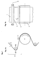
- Fig. 1a shows a side view of an embossing machine with an embossing unit in the form of an embossing cylinder 3 and a draw roller 4.
- the embossing machine leads a web 1 of an endless film in the conveying direction 2 along a distance S via the draw roller 4 to the embossing to.
- the web 1 contains first constituents of a security element, for example printed microstructure information.
- the first ingredients are supplemented with second ingredients to form a security element.
- the second constituents can be, for example, embossed structures, in particular microlens structures, which, together with the embossed structures, realize a moire magnifier as a security element.
- the first components are not shown on the lane 1 for the sake of simplicity.
- the endless film is pressed against the embossing cylinder 3, that the structures to be embossed are imaged on the web 1.
- the imprint of structures in this embodiment is the application of second components of the security element.
- other processing steps can be carried out in other embodiments, for example, the lamination of a film (see. Fig. 3 ).
- the embossing is then z. B. replaced by a corresponding laminating.
- this refers only by way of example to one of several exemplary embodiments, which may well use other apparatus and methods for applying the first and / or second components.
- the web 1 wraps around the embossing cylinder 3 in a predetermined angular range of z. B. 180 °.
- the effect of the draw roll 4 is best at high wrap. Therefore, the wrap of the draw roll can also be increased at the expense of the wrap of the embossing roll compared to designs without draw roll 4.
- the film of the web 1 is irradiated with UV radiation, for example, so that an embossing lacquer applied to the film is cured and thus the microstructure elements transferred in the embossing machine are "frozen” firmly into the embossing lacquer.
- the web 1 is fed via a deflection roller for further processing.
- the endless film can be rewound onto a roll or cut to length or cut and stacked in the form of individual sheets.
- the draw roll 4 is on one side, or preferably according to FIG Fig. 1b mounted on both sides, rotatable or pivotable. There is (each) a joint around which the draw roller 4 can be pivoted. On its other side, the draw roller 4 is suspended equally.
- a hydraulic cylinder, a lever mechanism or a spindle acts on a suspension and shifts it in any spatial directions, for example up or down, as the arrows in Fig. 1b Show.
- Fig. 1c shows the draw roll 4 in a view based on the Fig. 1a done from above.
- the draw roll 4 has a roll body 14 which extends along an axis 15. This is unlike conventional rollers not straight, but curved.
- the curvature is achieved in that the ends of the roller 4 are guided in a pillow block 16 and an abutment 17, which distort the roller in the curved shape.
- the roller body 14 has a biaxially curved lateral surface due to this curvature.
- the first curvature corresponds to that of a normal cylinder axis, ie in a section perpendicular to the axis 15, the lateral surface is circular, as well Fig. 1a shows. In the axis 15 contained section, the lateral surface is arcuate, such as Fig. 1c shows.
- Stretching roller 4 can be compensated for a distortion of the web 1 transverse to the conveying direction 2.
- the pillow block 16 and the anvil 17 are adjustable, as indicated by an arrow 19 in Fig. 1c is illustrated schematically.
- the roller rotates about its curved axis 15 (arrow 18).
- Fig. 1c shows an example also a stronger curvature (dashed line).
- the angle between a plane in which the axis 15 has the maximum curvature, and the plane in which the web 1 is conveyed can be adjusted.
- the draw roller 4 can thus be pivoted.
- such an adjustment is also shown (representation with 2-point 3-dash line).
- FIG. 1c In the in Fig.
- FIG. 2 shows the draw roller 4 and the untilted position is shown in dashed lines.
- Fig. 2b shows the initial state, ie the non-tilted drafting roller 4, whose axis of rotation in plan view of Fig. 2 thus is parallel to the axis of rotation of the embossing cylinder 3.
- Embossed structures 10, which are applied by the embossing cylinder 3 on the endless foil, are aligned parallel to a print motif 9. If the draw roller 4 according to Fig. 2a tilted down, there is an overstretching of the continuous film to the right, based on the direction of the endless film. Due to the curvature of the axis 15, the overstretching does not increase evenly towards the edge, whereby distortions transversely to the conveying direction 2 are compensated.
- Fig. 3 shows a further embodiment of the invention in a view similar to the Fig. 1a ,
- the stamping mill that is in the Fig. 1a formed by the elements 3, 5 and 6, replaced by a Kaschierwerk 11, which laminates on the web 1, which carries the first components of the security element to be generated, an additional web 12, which carries second components of the security element.
- the draw roll 4 is in turn suitably adjusted.
- Fig. 3 are purely exemplary two drafting rollers 4 drawn, which act on two routes S. This makes a particularly exact adjustment possible. Of course, depending on the requirement, only one section S can be provided with the draw roller 4.
- Fig. 3 shows by way of example further an optional measuring device 13b for measuring the position of the first components on the web 1 and optionally also the second components on the additional web 12.
- a similar measuring device 13b can also be used in an embodiment with embossing, z. B. in the construction according to Fig. 1 come into use.
Abstract
Die Erfindung betrifft ein Verfahren zum Herstellen eines Sicherheitselementes für Wertdokumente, Banknoten oder dergleichen, das folgende Schritte umfasst: Bereitstellen einer Bahn (1), die zur Herstellung einer Vielzahl des Sicherheitselementes eine Vielzahl an ersten Bestandteilen des Sicherheitselementes enthält, und Fördern der Bahn (1) längs einer Strecke (S) und Aufbringen einer Vielzahl an zweiten Bestandteilen des Sicherheitselementes auf die Bahn (1) am Ende der Strecke (S), wobei die Bahn in der Strecke (S) mittels einer verstellbaren Streckwalze (4), die eine zweiachsig gekrümmte Mantelfläche aufweist, quer zu einer Bahnlängsachse unterschiedlich gedehnt wird, um eine Registerlage zwischen ersten und zweiten Bestandteilen einzustellen.The invention relates to a method for producing a security element for documents of value, bank notes or the like, comprising the steps of: providing a web (1) which contains a plurality of first components of the security element for producing a plurality of the security element, and conveying the web (1 ) along a path (S) and applying a plurality of second components of the security element to the web (1) at the end of the path (S), the web in the path (S) by means of an adjustable draw roll (4) having a biaxial Has curved lateral surface is stretched differently across a web longitudinal axis, to set a register position between the first and second components.
Description
Die Erfindung betrifft ein Verfahren zum Herstellen eines Sicherheitselementes für Wertdokumente, Banknoten oder dergleichen, das folgende Schritte umfasst: Bereitstellen einer Bahn, die zur Herstellung einer Vielzahl des Sicherheitselementes eine Vielzahl an ersten Bestandteilen des Sicherheitselementes enthält, und Fördern der Bahn längs einer Strecke, und Aufbringen einer Vielzahl an zweiten Bestandteilen des Sicherheitselementes auf die Bahn am Ende der Strecke.The invention relates to a method for producing a security element for documents of value, banknotes or the like, comprising the steps of: providing a web which contains a plurality of first components of the security element for producing a plurality of the security element, and conveying the web along a route, and Applying a plurality of second components of the security element to the web at the end of the route.
Die Erfindung betrifft weiter eine Vorrichtung zum Herstellen eines Sicherheitselementes für Wertdokumente, Banknoten oder dergleichen, die umfasst: eine Fördereinrichtung zum Fördern einer Bahn, die zur Herstellung einer Vielzahl des Sicherheitselementes eine Vielzahl an ersten Bestandteilen des Sicherheitselementes enthält, längs einer Strecke und eine am Ende der Strecke angeordnete Aufbringeinrichtung zum Aufbringen einer Vielzahl an zweiten Bestandteilen des Sicherheitselementes auf die Bahn.The invention further relates to an apparatus for producing a security element for documents of value, bank notes or the like, comprising: a conveyor for conveying a web, which contains a plurality of first components of the security element, along a route and at the end to produce a plurality of the security element the path arranged applicator for applying a plurality of second components of the security element on the web.
Zur Verbesserung der Fälschungssicherheit von Wertdokumenten werden vermehrt Sicherheitselemente verwendet, die aus mehreren Bestandteilen bestehen, beispielsweise aus mehreren Lagen. Ein Beispiel für ein solches Sicherheitselement sind sogenannte Moire-Magnifier, bei denen Mikrostrukturen und Mikrolinsen übereinander aufgebracht werden. Die Mikrostrukturen liegen auf einem Substrat in einem genau definierten Raster und die Mikrolinsen müssen bezüglich Rasterweite und Lage dieses definierten Rasters in einer genau vorgeschriebenen Anordnung zu den Mikrostrukturen ausgebildet werden. Das Register zwischen diesen beiden Bestandteilen muss sehr genau eingehalten werden. Das ist fertigungstechnisch aufwendig, sowohl wenn die ersten und zweiten Bestandteile auf verschiedenen Bahnen ausgebildet werden, die zusammen verbunden werden müssen, als auch wenn die ersten und zweiten Bestandteile durch nacheinander abfolgende Druck- und/oder Prägeprozesse erzeugt werden. Bei einem gattungsgemäßen Verfahren oder einer gattungsgemäßen Vorrichtung muss das Aufbringen der zweiten Bestandteile in genauer Registerlage oder zumindest unter exakter Einhaltung der gewünschten Längenverhältnisse zu den ersten Bestandteilen, die bereits auf der Bahn vorhanden sind, erfolgen.To improve the security against forgery of value documents, security elements are increasingly used that consist of several constituents, for example of several layers. An example of such a security element are so-called moire magnifiers, in which microstructures and microlenses are applied one above the other. The microstructures lie on a substrate in a well-defined grid and the microlenses must be formed with respect to raster width and position of this defined grid in a precisely prescribed arrangement to the microstructures. The register between these two components must be followed very closely. This is technically complex, both when the first and second components are formed on different webs that need to be joined together, as well as when the first and second components are produced by successive printing and / or embossing processes. In a generic method or a generic device, the application of the second components in exact register position or at least under exact compliance with the desired length ratios to the first components that are already present on the track, done.
Die gattungsbildende
Die Entwicklung von Sicherheitselementen, die hinsichtlich ihrer Fälschungssicherheit nochmals verbessert sind, haben die Anforderungen in Bezug auf die Registergenauigkeit zwischen ersten und zweiten Bestandteilen nochmals gesteigert. Außerdem möchte man im Sinne einer effizienten Produktion möglichst breite Bahnen verwenden. Zudem werden für Sicherheitselemente vermehrt Materialmischungen eingesetzt, also beispielsweise die Kombination aus einer Kunststoffbahn, welche die Vielzahl an ersten Bestandteilen des Sicherheitselementes trägt, mit einer Papierbahn, welche die Vielzahl an zweiten Bestandteilen bereitstellt. Diese Materialmischungen sind fertigungstechnisch aufgrund unterschiedlicher thermischer Ausdehnungen, Erwärmungen beim Fördern einer Bahn etc. schwer zu beherrschen, was die Registerhaltigkeit beim Zusammenbringen der unterschiedlichen Materialien angeht. Schließlich möchte man bei der Herstellung auch die Fördergeschwindigkeit einer Bahn so hoch wie möglich wählen, um einen hohen Durchsatz zu erreichen.The development of security elements, which are further improved in terms of their security against counterfeiting, have further increased the requirements for register accuracy between the first and second components. In addition, you want to use the widest possible paths in terms of efficient production. In addition, material mixtures are increasingly used for security elements, that is, for example, the combination of a plastic web, which carries the plurality of first components of the security element, with a paper web, which provides the plurality of second components. These material mixtures Manufacturing technology are difficult to control due to different thermal expansions, warming when conveying a web, etc., as regards the register accuracy when bringing together the different materials. Finally, one would like to choose the production speed of a web as high as possible in order to achieve a high throughput.
Der Erfindung liegt deshalb die Aufgabe zugrunde, ein Verfahren sowie eine Vorrichtung der eingangs genannten Art so weiterzubilden, dass die Registergenauigkeit zwischen den auf der Bahn vorhandenen ersten Bestandteilen und dem Aufbringen der zweiten Bestandteile möglichst exakt eingestellt werden kann.The invention is therefore based on the object, a method and an apparatus of the type mentioned in such a way that the register accuracy between the existing on the web first components and the application of the second components can be set as accurately as possible.
Diese Aufgabe wird erfindungsgemäß mit einem Verfahren zum Herstellen eines Sicherheitselementes für Wertdokumente, Banknoten oder dergleichen gelöst, das folgende Schritte umfasst:
- a) Bereitstellen einer Bahn, die zur Herstellung einer Vielzahl des Sicherheitselementes eine Vielzahl an ersten Bestandteilen des Sicherheitselementes enthält, und Fördern der Bahn längs einer Strecke, und
- b) Aufbringen einer Vielzahl an zweiten Bestandteilen des Sicherheitselementes auf die Bahn am Ende der Strecke, wobei
- c) die Bahn in der Strecke mittels einer verstellbaren Streckwalze, die eine zweiachsig gekrümmte Mantelfläche aufweist, quer zu einer Bahnlängsachse unterschiedlich in Längs- und/ oder Querrichtung gedehnt wird, um eine Registerlage zwischen ersten und zweiten Bestandteilen einzustellen und/ oder bestimmte Längenverhältnisse zwischen ersten und zweiten Bestandteilen einzuhalten.
- a) providing a web which contains a plurality of first components of the security element for producing a plurality of the security element, and conveying the web along a route, and
- b) applying a plurality of second components of the security element to the web at the end of the route, wherein
- c) the web in the stretch is stretched differently in the longitudinal and / or transverse direction transversely to a web longitudinal axis by means of an adjustable draw roll, which has a biaxially curved lateral surface, about a register position between first and second components adjust and / or maintain certain length ratios between the first and second components.
Die Aufgabe wird weiter gelöst mit einer Vorrichtung zum Herstellen eines Sicherheitselementes für Wertdokumente, Banknoten oder dergleichen, die umfasst:
- a) eine Fördereinrichtung zum Fördern einer Bahn, die zur Herstellung einer Vielzahl des Sicherheitselementes eine Vielzahl an ersten Bestandteilen des Sicherheitselementes enthält, längs einer Strecke, und
- b) eine am Ende der Strecke angeordnete Aufbringeinrichtung zum Aufbringen einer Vielzahl an zweiten Bestandteilen des Sicherheitselementes auf die Bahn, wobei
- c) die Vorrichtung in der Strecke eine verstellbare Streckwalze aufweist, die eine zweiachsig gekrümmte Mantelfläche aufweist, um die Bahn quer zu einer Bahnlängsachse unterschiedlich in Längs- und/ oder Querrichtung zu dehnen und eine Registerlage zwischen ersten und zweiten Bestandteilen einzustellen und/ oder bestimmte Längenverhältnisse zwischen ersten und zweiten Bestandteilen einzuhalten.
- a) a conveyor for conveying a web, which contains a plurality of first components of the security element, along a route, and for producing a plurality of the security element
- b) an applicator arranged at the end of the track for applying a plurality of second components of the security element to the web, wherein
- c) the device has an adjustable drafting roller in the path, which has a biaxially curved lateral surface in order to stretch the web transversely to a web longitudinal axis differently in the longitudinal and / or transverse direction and to set a register position between first and second components and / or certain aspect ratios between the first and second components.
Erfindungsgemäß wird eine Streckwalze eingesetzt, die eine zweidimensional gekrümmte Mantelfläche hat. Diese Streckwalze erlaubt es, die Spannung bzw. den Zug in der Mitte der Bahn gegenüber den Rändern einzustellen, beispielsweise den Zug in der Mitte der Bahn zu reduzieren (bevorzugter Fall) oder zu erhöhen. Auf diese Weise können die Spannungsverhältnisse in der Bahn so eingestellt werden, dass das Aufbringen der Vielzahl an zweiten Bestandteilen des Sicherheitselementes im Register zu den ersten Bestandteilen auf der Bahn geschieht. Die Bahn kann weiter verarbeitet werden, d. h. das Ende der Strecke ist in der Regel nicht das Ende der Bearbeitungsanlage.According to the invention, a draw roll is used which has a two-dimensionally curved lateral surface. This draw roll makes it possible to adjust the tension or tension in the middle of the web with respect to the edges, for example to reduce (or preferential) or to increase the tension in the middle of the web. In this way, the tension conditions in the web can be adjusted so that the application of the plurality of second components of the security element in the register to the first components happening on the track. The web can be further processed, ie the end of the route is usually not the end of the processing plant.
Unter einer zweiachsigen Krümmung wird hinsichtlich der Mantelfläche verstanden, dass die Mantelfläche in zwei Schnittebenen, welche nicht parallel zueinander liegen, also insbesondere orthogonal sein können, jeweils eine Krümmung hat. Der Begriff der zweiachsigen Krümmung ist also im hier zugrunde liegenden Verständnis mit dem Begriff einer zweidimensional gekrümmten Fläche im mathematischen Sinne identisch. Die Krümmung ist in jeder Schnittebene nicht darauf beschränkt, dass sie einer Kreisgeometrie genügt. Vielmehr fallen auch beliebig geformte Mantelflächen unter den Begriff der zweiachsigen oder zweidimensionalen Krümmung. Die zweiachsig gekrümmte Mantelfläche der Streckwalze führt dazu, dass die Streckwalze nicht mehr ein reiner Kreiszylinder im mathematischen Sinne ist. Im mathematischen Sinne wird eine zylindrische Mantelfläche bekanntermaßen dann erhalten, wenn man eine geschlossene Bahnkurve (die sogenannte Erzeugende) längs einer Geraden verschiebt. Herkömmliche Walzen haben als Erzeugende einen Kreis, der längs einer Geraden verschoben wird, sie sind Kreiszylinder. Die Streckwalze hat als Erzeugende in bevorzugten Ausführungsformen ebenfalls einen Kreis, der nun jedoch nicht entlang einer Geraden, sondern längs einer gekrümmten Bahnkurve verschoben wird. Der Kreis als Erzeugende ist für eine einachsige Krümmung verantwortlich, die gekrümmte Bahnkurve, entlang der der Kreis zur Erzeugung der Mantelfläche verschoben wird, bewirkt eine weitere Achse der Krümmung.With regard to the lateral surface, a biaxial curvature is understood to mean that the lateral surface in each case has a curvature in two sectional planes which are not parallel to one another, ie may be orthogonal in particular. The concept of biaxial curvature is therefore identical in the underlying understanding with the concept of a two-dimensionally curved surface in the mathematical sense. The curvature in each section plane is not limited to satisfying a circular geometry. Rather, arbitrarily shaped lateral surfaces also fall under the term biaxial or two-dimensional curvature. The biaxially curved lateral surface of the draw roll causes the draw roll is no longer a pure circular cylinder in the mathematical sense. In the mathematical sense, a cylindrical surface is known to be obtained when moving a closed trajectory (the so-called generator) along a straight line. Conventional rolls have as a generator a circle which is displaced along a straight line, they are circular cylinders. The draw roll also has a circle as a generator in preferred embodiments, which is now displaced not along a straight line, but along a curved trajectory. The circle as a generator is responsible for a uniaxial curvature, the curved trajectory, along which the circle is moved to generate the lateral surface, causes a further axis of curvature.
Der erfindungsgemäße Ansatz erlaubt es beim Fördern der Bahn in der Bearbeitungsmaschine, den Zug auf die Bahn so einzustellen, dass Verzerrungen über die Breite der Bahn ausgeglichen werden. Dadurch können beim Aufbringen der zweiten Bestandteile bzw. ganz allgemein bei der aufeinander abgestimmten Ausführung von Bearbeitungsschritten an der Bahn Verzerrungen vermieden werden, die zur Produktion von Ausschuss führen würden. Die Bearbeitungsschritte können beispielsweise die Erzeugung eines gewünschten Gesamtmotivs umfassen, bei denen in einem ersten Bearbeitungsschritt eine erste Druckschicht auf die Bahn aufgebracht wird. Dies kann das Bereitstellen der zu fördernden Bahn sein bzw. in der Vorrichtung eine vor Beginn der Strecke liegende Bearbeitungseinrichtung. Die Druckschicht kann beispielsweise ein Motivraster für einen Moire-Magnifier, einen Modulo-Mapper oder ein Kippbild mit oder ohne Vergrößerungswirkung sein. Im zweiten Bearbeitungsschritt erfolgt das Aufbringen der zweiten Bestandteile. Hierbei kann es sich beispielsweise um das Aufbringen einer Mikrolinsenschicht mit einem Mikrolinsenraster handeln, das in einem vorgegebenen Verhältnis zum ersten Motivraster zu stehen hat, um ein gewünschtes Gesamtmotiv zu erreichen. Die erfindungsgemäße Streckwalze erlaubt es, Verzerrungen über die Breite der Bahn, d. h. quer zur Förderrichtung auszugleichen. Störungen eines der beiden Motivraster und Störungen des Gesamtmotivs werden vermieden. Die Reihenfolge, in der die ersten und zweiten Bestandteile aufgebracht werden, kann vertauscht werden.The approach of the present invention, when conveying the web in the processing machine, allows the tension on the web to be adjusted to compensate for distortions across the width of the web. As a result, when applying the second components or more generally in the successive coordinated execution of processing steps on the web avoiding distortions that would lead to the production of rejects. The processing steps may include, for example, the generation of a desired overall motif in which a first print layer is applied to the web in a first processing step. This can be the provision of the web to be conveyed or in the device a processing device located before the start of the route. The print layer can be, for example, a motif grid for a moiré magnifier, a modulo mapper or a tilted image with or without magnification effect. In the second processing step, the application of the second components. This may be, for example, the application of a microlens layer with a microlens grid, which has to stand in a predetermined relationship to the first motif grid in order to achieve a desired overall motif. The draw roll according to the invention makes it possible to compensate for distortions across the width of the web, ie transversely to the conveying direction. Disturbances of one of the two motif grids and disturbances of the overall motive are avoided. The order in which the first and second components are applied can be reversed.
Da das Ausmaß von Verzerrungen quer zur Förderrichtung im Allgemeinen mit der Breite der Bahn zunimmt, erreicht die erfindungsgemäße Lösung einen besonderen Wirtschaftlichkeitsvorteil dahingehend, dass breitere Bahnen verwendet werden können, die ansonsten für herkömmliche Herstellvorrichtungen/-verfahren aufgrund von Verzerrungen, die beispielsweise durch die üblichen Fördervorrichtungen und/ oder durch Inhomogenitäten im Material der Bahn entstehen oder verschlimmert werden können, nicht geeignet wären.Since the amount of cross-machine directional distortion generally increases with the width of the web, the solution of the invention achieves a particular economics benefit in that wider webs can be used which would otherwise be required for conventional manufacturing apparatus / methods due to distortions caused by, for example, the conventional Conveying devices and / or caused by inhomogeneities in the material of the web or could be made worse, would not be suitable.
Die Vorrichtung kann am Anfang der Strecke eine Bearbeitungseinrichtung, z. B. ein Druckwerk, aufweisen, die auf der Bahn die ersten Bestandteile erzeugt.The device can at the beginning of the route a processing device, for. B. a printing unit, which generates the first components on the web.
In einer bevorzugten Ausführungsform enthält die einlaufende Folie bereits die ersten Bestandteile. Dann durchläuft die Folie ein Druckwerk, in dem ein UV-härtbares Medium (Prägelack) aufgetragen wird. Anschließend wird die Bahn zu einer Prägestation weiterbefördert, die die zweiten Bestandteile durch Prägung und UV-Bestrahlung erzeugt. Dort muss die Dehnung der einlaufenden Folie so korrigiert sein, dass die zweiten Bestandteile hinsichtlich Lage und Abmessung wunschgemäß mit den ersten Bestandteilen harmonieren. Bevorzugt erfolgt die Korrektur unmittelbar vor dem Prägewerkzeug. Anstelle eines UV-härtbaren Mediums kann auch ein thermoplastisches Medium oder eine thermoplastisch verformbare Folie eingesetzt werden.In a preferred embodiment, the incoming film already contains the first constituents. Then the film passes through a printing unit, in which a UV-curable medium (embossing lacquer) is applied. Subsequently, the web is conveyed to an embossing station, which generates the second components by embossing and UV irradiation. There, the elongation of the incoming film must be corrected so that the second components harmonize as desired with the first components in terms of position and dimension. Preferably, the correction takes place immediately before the embossing tool. Instead of a UV-curable medium and a thermoplastic medium or a thermoplastic deformable film can be used.
Die Bearbeitungsschritte, insbesondere das Erzeugen der ersten und zweiten Bestandteile, können sowohl auf ein und derselben Seite der Bahn erfolgen, wie auch auf unterschiedlichen Seiten.The processing steps, in particular the production of the first and second components, can take place both on one and the same side of the web, as well as on different sides.
Ein positiver Nebeneffekt der erfindungsgemäßen Vorrichtung bzw. des erfindungsgemäßen Verfahrens ist, dass die Anforderung an die Folienqualität hinsichtlich Dehnung bei unterschiedlichem Zug bzw. unterschiedlichen Spannungen merklich reduziert sind. Man muss nicht mehr zwingend Folien verwenden, die ein sehr homogenes Dehnungsverhalten haben, sondern kann bei Folienmaterial, das ein vergleichsweise inhomogenes Dehnungsverhalten zeigt, durch geeignetes Einstellen der Streckwalze eine materialbedingt inhomogene Dehnung vergleichmäßigen.A positive side effect of the device according to the invention or of the method according to the invention is that the requirement for the film quality with regard to stretching at different tension or different voltages is markedly reduced. It is no longer absolutely necessary to use films which have a very homogeneous expansion behavior, but can even out a material-related inhomogeneous expansion in the case of film material which exhibits a comparatively inhomogeneous expansion behavior by suitably setting the draw roll.
Als Streckwalze kommen verschiedenste Bauformen in Frage. Eine besonders bevorzugte Bauform ist eine Walze, die die Form eines gebogenen Kreiszylinders hat. Es handelt sich also um eine an und für sich kreiszylindrische Walze, wobei der Begriff "Kreiszylinder" hier im mathematischen Sinne verstanden wird. Er beschreibt einen Zylinder, der durch Verschieben eines Kreises, der die Erzeugende im mathematischen Sinne ist, längs einer Achse gewonnen wird. Durch Biegung dieser Achse erhält man die erfindungsgemäß vorgesehene Streckwalze mit zweidimensional gekrümmter Mantelfläche. Um die Dehnungs- und Spannungsverhältnisse in der Bahn vor dem Aufbringen der Vielzahl an zweiten Bestandteilen des Sicherheitselementes einstellen zu können, ist in einer Ausführungsform die Biegung der kreiszylindrischen Walze, d. h. die Biegung der Achse der Walze einstellbar. In einer bevorzugten Ausführungsvariante ist die gebogene Walze an ihren beiden Enden zusätzlich derart drehbar gelagert, dass die Ebene der maximalen Biegung relativ zur Ebene der durchlaufenden Folienbahn geneigt werden kann (schwenkbare Walze). Hierbei ist es möglich, die Richtung, in die die maximale Biegung zeigt, zu verändern. Gleichzeitig ist es zweckmäßig, die außerhalb der zu fördernden Bahn liegenden Endpunkte der Walze so verstellbar zu gestalten, wie dies
Das Aufbringen der Vielzahl an zweiten Bestandteilen des Sicherheitselementes kann in einer ersten Ausführungsform dadurch erfolgen, dass eine Zusatzbahn, die die Vielzahl von zweiten Bestandteilen enthält, bereitgestellt und mit der Bahn verbunden wird. Hier ist die Erfindung besonders vorteilhaft in Fällen, in denen die Zusatzbahn aus einem anderen Material besteht als die Bahn. Beispielsweise können unterschiedliche Dehnungen des Materialmixes Kunststoffbahn/Papierbahn gut ausgeglichen werden. Bei der Vorrichtung wird in dieser Ausführungsform eine Aufbringeinrichtung vorgesehen, die ein Kaschierwerk aufweist, und eine Zufuhreinrichtung führt die Zusatzbahn dem Kaschierwerk zu. In einer weiteren Ausführungsform wird die Vielzahl an zweiten Bestandteilen mittels eines Druck- oder Prägeprozesses aufgebracht. Die Vorrichtung weist dann als Aufbringeinrichtung ein Druck- oder Prägewerk auf. Im Herstellverfahren wird am Ende der Strecke durch einen Druck- oder Prägezylinder, durch den die Bahn geführt wird, die Vielzahl an zweiten Bestandteilen aufgebracht.The application of the plurality of second constituents of the security element can in a first embodiment be carried out by providing an additional web containing the plurality of second constituents and connecting it to the web. Here, the invention is particularly advantageous in cases where the additional web is made of a different material than the web. For example, different strains of the material mix plastic web / paper web can be well balanced. In the device In this embodiment, an application device is provided which has a laminating unit, and a supply device feeds the additional path to the laminating unit. In a further embodiment, the plurality of second constituents are applied by means of a printing or embossing process. The device then has as an applicator on a printing or embossing. In the manufacturing process, the plurality of second components is applied at the end of the route through a printing or embossing cylinder, through which the web is guided.
Eine weitere Variante für die Walze mit zweidimensional gekrümmter Mantelfläche ist eine sogenannte S-Walze: Sie enthält in ihrem Inneren eine Mehrzahl von Elementen, mit deren Hilfe die Ausdehnung der Ummantelung an der jeweiligen Stelle beeinflusst werden kann. Sie weist den Vorteil auf, dass die Form der Walze sehr flexibel gestaltet werden kann, insbesondere komplizierter sein kann als eine einfache Biegung.A further variant for the roller with a two-dimensionally curved lateral surface is a so-called S-roll: it contains in its interior a plurality of elements with the aid of which the extent of the sheathing at the respective point can be influenced. It has the advantage that the shape of the roller can be made very flexible, in particular can be more complicated than a simple bend.
Anstelle eines gebogenen Kreiszylinders, dessen Biegung und optional auch Einschwenkposition verstellbar sind, kann auch ein Zylinder verwendet werden, der im Querschnitt eine konvexe oder konkave Form hat, also tonnen- oder spindelförmig ist. Hier ist die Krümmung der Mantelfläche nicht veränderbar, jedoch kann man einen Zylinder verwenden, dessen Grundform an Normalbedingungen bezüglich des Streckens der Bahn angepasst ist. Alternative Mantelflächen sind durch in der Mitte aneinandergrenzende Kegel oder auch wesentlich kompliziertere Formen repräsentiert, die durch Fräsen oder Drehen realisiert werden können und die Dehnung der Folie bzw. des geförderten Mediums in der gewünschten Weise beeinflussen. Anders als bei einem gebogenen Kreiszylinder werden solche Walzen während des Betriebes, d. h. beim Rotieren nicht fortlaufend verformt. Die Gefahr einer Materialermüdung ist geringer, bzw. es können einfachere Materialien für die Walze verwendet werden.Instead of a curved circular cylinder whose bending and optionally also pivoting position are adjustable, it is also possible to use a cylinder which has a convex or concave shape in cross-section, ie is barrel-shaped or spindle-shaped. Here, the curvature of the lateral surface is not changeable, but one can use a cylinder whose basic shape is adapted to normal conditions with respect to the stretching of the web. Alternative lateral surfaces are represented by cones in the middle or else considerably more complicated shapes, which can be realized by milling or turning and which influence the expansion of the film or the conveyed medium in the desired manner. Unlike a curved circular cylinder such rollers are not continuously deformed during operation, ie during rotation. The danger of a Material fatigue is lower or simpler materials for the roller can be used.
In einer weiteren Ausführungsform verfügt die eingesetzte Walze über eine die Haftung bzw. Reibung zum eingesetzten Medium beeinflussende Ummantelung. Lokale, über die Länge der Walze hinweg variierende Haftungsoder Reibungseigenschaften können die Dehnung des geförderten Mediums ebenfalls im gewünschten Sinne beeinflussen. Mit positivem Ergebnis wurde eine Rillierung einer Kunststoffummantelung einer Streckwalze getestet. Eine Alternative zur Erzeugung eines variablen Haftungsprofils besteht im Einsatz einer lokal aufbringbaren elektrostatischen Aufladung der Walze.In a further embodiment, the roller used has a sheath which influences the adhesion or friction to the medium used. Local adhesion or frictional properties varying over the length of the roll can also affect the elongation of the conveyed medium in the desired sense. With a positive result, a grooving of a plastic coating of a draw roll was tested. An alternative to producing a variable adhesion profile is to use a locally applicable electrostatic charge on the roller.
In einer besonders bevorzugten Ausführungsform wird die Registerhaltigkeit zwischen ersten und zweiten Bestandteilen im Betrieb fortwährend überwacht und die Stellung der Streckwalze im Rahmen einer Regelung entsprechend eingestellt. Die Überwachung kann nach dem Aufbringen der Vielzahl an zweiten Bestandteilen des Sicherheitselementes erfolgen. Diese Messung kann besonders einfach ausgeführt werden, hat jedoch den Nachteil, dass Fehler im Register zwischen ersten und zweiten Bestandteilen erst dann erkannt werden, wenn bereits Abweichungen vom Idealfall aufgetreten und im Produkt irreparabel vorhanden sind. Es ist deshalb eine weitere Ausführungsform vorgesehen, welche mittels einer Messeinrichtung die Lage der ersten Bestandteile an verschiedenen Stellen quer über die Bahn vor dem Aufbringen der zweiten Bestandteile ermittelt und die Stellung der Streckwalze abhängig von der ermittelten Lage einstellt. Die Messeinrichtung kann dabei stromauf der Streckwalze liegen. Dazu muss man lediglich die Wirkung einer bestimmten Streckwalzenstellung bezüglich einer Lageverschiebung der ersten Bestandteile aufgrund einer Dehnung der Bahn, welche die Streckwalze verursacht, vorab ermitteln. Dann wird in dieser Ausführungs-form abhängig von der ermittelten Lage der ersten Bestandteile im aktuellen Betrieb die Streckwalze geeignet eingestellt.In a particularly preferred embodiment, the registration between first and second components is continuously monitored during operation and the position of the draw roller is adjusted accordingly within the scope of a regulation. The monitoring can be done after the application of the plurality of second components of the security element. This measurement can be carried out particularly simply, but has the disadvantage that errors in the register between the first and second components are only recognized if deviations from the ideal case have already occurred and are irreparably present in the product. There is therefore provided a further embodiment, which determines by means of a measuring device, the position of the first components at different locations across the web before applying the second components and adjusts the position of the draw roller depending on the determined position. The measuring device can be upstream of the draw roll. For this purpose, one only has to determine in advance the effect of a certain draw roll position with respect to a positional shift of the first components due to an elongation of the web which causes the draw roll. Then in this embodiment form Depending on the determined position of the first constituents in the current operation, the draw roll set appropriately.
In einer anderen Ausführungsform liegt die Messeinrichtung stromab der Streckwalze. Hier kann die Streckwalze im Sinne einer Regelung eingestellt werden, um die Lage der ersten Bestandteile vorbestimmt einzustellen. Anders als beim Messen nach dem Aufbringen der zweiten Bestandteile, kann hier immer noch reagiert werden, wenn eine Fehllage der ersten Bestandteile vorliegt, da ein Verstellen der Streckwalze auf die gesamte Bahnstrecke bis zum Aufbringen der zweiten Bestandteile wirkt. Das Messen zwischen der Streckwalze und dem Ende der Strecke, d. h. an dem Punkt, an dem das Aufbringen der zweiten Bestandteile beginnt, hat somit den Vorteil, dass die Produktion von Ausschuss vermieden wird und dennoch eine relativ einfache Regelung ausgeführt werden kann, deren Stellgröße die Einstellung der Streckwalze ist. Für diese Ausführungsform weist die Erfindung eine Lagedetektoreinrichtung auf, die auf der Strecke angeordnet ist und zum Ermitteln einer Lage der ersten Bestandteile ausgebildet ist. Weiter umfasst die Vorrichtung ein entsprechendes Steuergerät, das die verstellbare Streckwalze ansteuert, insbesondere in Form einer Regelung.In another embodiment, the measuring device is downstream of the draw roll. Here, the draw roll can be adjusted in the sense of a regulation to set the position of the first components predetermined. Unlike when measuring after applying the second constituents, it is still possible to react here if there is a misplacement of the first constituents, since an adjustment of the draw roll on the entire web path acts until the second constituents are applied. Measuring between the draw roll and the end of the stretch, d. H. Thus, at the point where the application of the second constituents begins, there is the advantage of avoiding the production of rejects, and nevertheless a relatively simple control can be carried out whose manipulated variable is the adjustment of the draw roll. For this embodiment, the invention comprises a position detector device, which is arranged on the track and is designed to determine a position of the first components. Furthermore, the device comprises a corresponding control device which controls the adjustable draw roller, in particular in the form of a control.
Bei Ausführungsformen, die zwei oder mehr Bahnen verbinden, befinden sich zweckmäßigerweise an allen Bahnen Messeinrichtungen.In embodiments which connect two or more webs, measuring devices are expediently located on all webs.
Für die Verstellung der Streckwalze kommen alle geeigneten mechanischen Mittel in Frage, die beispielsweise in der
Hinsichtlich der Messung der Lage der ersten Bestandteile gilt für ein Sicherheitselement, das einen Moire-Magnifier umfasst, Folgendes zur Lageerfassung:
- Bevorzugterweise wird ein vergrößertes Moire-Bild mittels einer Bilderkennung erfasst, die die Größe des Moire-Bildes und/ oder dessen Verzerrung ermittelt und zur Basis der Steuerung der Streckwalze macht. Ein vergrößertes Moire-Bild wird z. B. mittels einer Kamera beobachtet, der aktuelle Vergrößerungsfaktor und die Abweichung vom beabsichtigten Vergrößerungsfaktor ermittelt und damit die Einstellung der Streckwalze derart beeinflusst, dass sich der Vergrößerungsfaktor wieder in Richtung Sollwert bewegt, und zwar im Idealfall über die ganze Bahnbreite.
- Preferably, an enlarged moiré image is detected by means of an image recognition which determines the size of the moiré image and / or its distortion and makes it the basis of the control of the draw roller. An enlarged Moire image is z. B. observed by means of a camera, the current magnification factor and the deviation from the intended magnification factor determined and thus affects the setting of the draw roller such that the magnification factor moves back towards the target value, ideally over the entire web width.
Wird z. B. eine Moiré-Vergrößerung von 200 angestrebt, bei der das vergrößerte Bild für den Betrachter den Anschein hat, tiefer als die Betrachtungsebene zu liegen, so muss das Mikrostrukturraster gegenüber dem Mikrolinsenraster quer und längs der Folientransportrichtung um 0,5 % kleiner angelegt sein als das Mikrolinsenraster. So ist z. B. gemäß dem Prägewerk das Mikrolinsenraster um 0,5 % größer als das Mikrobildraster. Im ersten Arbeitsgang - bzw. in einer ersten Bearbeitungsstation - werden die Mikrolinsen hergestellt (vorzugsweise durch Prägen in transparentem Lack). Wird per Kamera und nachgeschalteter Bildauswertung beim zweiten Arbeitsgang - dem Herstellen der Mikrostrukturen - eine Fehlpasserung zwischen den Mikrostrukturen und den Mikrolinsen ermittelt, wird dieser durch eine automatische Nachregelung der Streckwalze entgegengewirkt, indem die Vordehnung der Folie erhöht wird, bis sich die gewünschte Passerung wieder einstellt. Dadurch wird die Gutbreite, d. h. die Breite des Bahnabschnitts mit korrekt vergrößerten Moire-Strukturen, möglichst auf die gesamte Breite der Bahn vergrößert.If z. For example, if a moiré magnification of 200 is sought, where the magnified image appears to be lower than the viewing plane for the viewer, then the microstructure is required to be 0.5% smaller than the microlens grid across and along the film transport direction the microlens grid. So z. B. according to the embossing the microlens grid by 0.5% larger than the microimage grid. In the first operation - or in a first processing station - the microlenses are produced (preferably by embossing in transparent lacquer). If a maladaptation between the microstructures and the microlenses is determined by the camera and downstream image analysis during the second operation - the production of the microstructures, this is counteracted by an automatic readjustment of the draw roll by increasing the pre-stretching of the film until the desired registration is restored , As a result, the material width, ie the width of the web section with correctly enlarged moire structures, is increased as far as possible over the entire width of the web.
Bei bekannter Mikrolinsen- und Mikrobild-Rastergeometrie kann aus der Abweichung zwischen vergrößertem Nominalbild und dem real sichtbaren vergrößerten Moire-Bild ermittelt werden, welcher Rasterweitenunterschied und welcher Winkel zwischen Mikrolinsen- und Mikrostrukturraster eingestellt ist. Nach Vergleich von Ist- und Sollwert kann die Streckwalze nachgestellt werden.In known microlens and microimage raster geometry can be determined from the deviation between the enlarged nominal image and the real visible enlarged moire image, which raster width difference and which angle is set between microlens and Mikrostrukturraster. After comparing the actual and setpoint, the draw roller can be readjusted.
Es können mittels Mikrolinsen und Mikrobildern und einer geeigneten Rasteranordnung der beiden Strukturen zueinander auch sehr hohe Vergrößerungsfaktoren erzeugt werden. Es können z. B. Moiré-Bilder erzeugt werden, die scheinbar bis zu mehr als 1 cm über oder unter der Folienebene zu liegen scheinen und eine Größe von mehreren Millimetern aufweisen. Solche Moire-Bilder sind aufgrund ihrer Größe und des auffälligen Tiefen- bzw. Höheneffektes für Sicherheitselemente sehr gut geeignet. Für ein Sicherheitselement steht jedoch auf einer Banknote immer nur sehr begrenzt Platz zur Verfügung. Z. B. in einem Sicherheitsfaden, der typischerweise eine Breite von 2 mm bis 6 mm aufweist, soll ein gut wahrnehmbares Motiv mit mehreren Millimetern Größe zentral in die Mitte des Fadens positioniert werden. In einem Folienpatch mit einer typischen lateralen Ausdehnung von ca. 20 mm kann ein Moire-Bild mit ca. 10 mm so positioniert sein, dass es bei senkrechtem Betrachtungswinkel zentral auf dem Patch erscheint. Bei so großen Moire-Motiven muss darauf geachtet werden, dass die vergrößerten Motive auf allen Wertdokumenten mit ähnlicher Größe und ähnlicher Position im Folienelement erscheinen. Bei der Herstellung ist dies sehr schwierig zu bewerkstelligen, da sich bei einer lateralen Verschiebung des Mikrolinsen- zum Mikrostrukturraster von nur einer Rasterweite (typischerweise 10 µm bis 50 µm) das vergrößerte Motiv bereits lateral um eine Strecke verschiebt, die sich aus Mikrostrukturrasterweite mal Vergrößerungsfaktor ergibt und daher im Bereich von mehreren Millimetern liegt. Dies bedeutet im Umkehrschluss, dass bei typischen Moire-Magnifiern eine Positionsgenauigkeit eines großen Moire-Bildes nur zu bewerkstelligen ist, wenn die Mikrobilder mit einer Positionsgenauigkeit von wenigen Mikrometern unter die Mikrolinsen eingesteuert werden. Als Beispiel seien Mikrolinsen und Mikrobilder mit einer Rasterweite von 30 µm angenommen und ein angestrebtes vergrößertes Bild von 9 mm. Der Vergrößerungsfaktor ist hierbei 300. Wenn dieses vergrößerte Bild von seiner Nominalposition auf der Folie um ± 2 mm abweichen darf, so bedeutet dies, dass das Mikrobild unter der Mikrolinse eine laterale Positionstoleranz von 6,7 µm einhalten muss. Bevorzugt wird deshalb das vergrößerte Moire-Bild selbst benutzt. Es wird per Kamera und Bildauswertung die Größe und die Position des Moire-Bildes erfasst und mit dieser Information die Streckwalze in der Zuführung der Bahn so nachgeregelt werden, dass das vergrößerte Moire-Bild an der Sollposition auf der Folie ist. Die Regelstrecke bewegt sich hierbei lediglich im Bereich von 1 µm bis 50 µm.Very high magnification factors can also be generated by means of microlenses and microimages and a suitable grid arrangement of the two structures relative to one another. It can z. For example, moiré images may be produced which appear to be above or below the film plane by more than 1 cm and have a size of several millimeters. Moire images of this kind are very well suited for security elements because of their size and the striking depth or height effect. For a security element, however, there is always very limited space available on a banknote. For example, in a security thread, which typically has a width of 2 mm to 6 mm, a well-perceived motif with several millimeters in size should be positioned centrally in the middle of the thread. In a foil patch with a typical lateral extent of approx. 20 mm, a Moire image with approx. 10 mm can be positioned so that it appears centrally on the patch with a vertical viewing angle. With moire motifs as large as this, care must be taken to ensure that the enlarged motifs appear on all value documents of similar size and position in the slide element. This is very difficult to accomplish in the production because, with a lateral shift of the microlens to the microstructure grid of only one screen pitch (typically 10 μm to 50 μm), the magnified motif already shifts laterally by a distance resulting from microstructure grid size times magnification factor and therefore in the range of several millimeters. This implies, conversely, In the case of typical Moire magnifiers, a positional accuracy of a large Moire image can only be achieved if the microimages are controlled with a position accuracy of a few micrometers below the microlenses. As an example, assume microlenses and microimages with a pitch of 30 microns and a desired enlarged image of 9 mm. The magnification factor here is 300. If this enlarged image may deviate from its nominal position on the film by ± 2 mm, this means that the micro image under the microlens must comply with a lateral positional tolerance of 6.7 μm. Preferably, therefore, the enlarged moiré image itself is used. The size and the position of the moiré image are recorded by means of a camera and image evaluation, and with this information the draw roller in the feed of the web is adjusted so that the enlarged moiré image is at the desired position on the film. The controlled system moves only in the range of 1 .mu.m to 50 .mu.m.
In einer vereinfachten Ausführungsform wird nicht die absolute Positioniergenauigkeit eingestellt, sondern die relativen Längenverhältnisse werden angepasst, um die richtige Vergrößerung zu erzielen.In a simplified embodiment, the absolute positioning accuracy is not set, but the relative aspect ratios are adjusted to achieve the proper magnification.
Der Begriff der Lageerfassung der ersten Bestandteile umfasst also auch die Lageerfassung der Kombination aus ersten und zweiten Bestandteilen und insbesondere die Auswertung eines Moire-Bildes hinsichtlich Vergrößerung und/oder Verzerrung. Bevorzugt wird aus der Lageerfassung eine Steuergröße für die Einfahrposition oder -winkel der Streckwalze. Nun können die Moire-Motive in Art und Größe für unterschiedliche Anwendungen recht unterschiedlich ausfallen. Die Auswertung von unterschiedlich großen und formvariablen Motiven hinsichtlich Größe und Lage ist für Bildauswertungen immer schwierig. Bevorzugt werden deshalb adaptive Systeme auf das jeweilige Motiv zuerst trainiert.The concept of position detection of the first components thus also includes the position detection of the combination of first and second components and in particular the evaluation of a moiré image with regard to magnification and / or distortion. From the position detection is preferably a control variable for the retraction position or angle of the draw roll. Now the moire motifs can be quite different in type and size for different applications. The evaluation of different size and shape variable motifs in terms of size and location is for image analysis always difficult. Therefore, adaptive systems are preferably first trained on the respective motif.
In einer bevorzugten Weiterbildung werden Kontrollmotive auf der Bahn und gegebenenfalls auf der Zusatzbahn vorgesehen, die besonders bevorzugt an den Folienrändern und/ oder über die Folienbreite in ihrer Größe und gegebenenfalls Position von dem Kamera-Erfassungs- und Auswertetool bewertet werden und damit die jeweils notwendige Nachregelung der Foliendehnung eingeleitet werden. Beispielhaft sei als einfaches Kontrollmotiv ein Streifendesign von abwechselnd hellen und dunkleren Streifen in und senkrecht zur Folienlaufrichtung erwähnt. Die Streifen haben idealerweise die gleiche oder eine leicht unterschiedliche Periodizität im Vergleich zum Mikrolinsenraster. Dieses Streifendesign erlaubt es, Bahnverzerrungen über die Erfassung der moirévergrößerten Streifen zu erfassen, sowie Verkippungen zwischen Mikrolinsen- und Mikrostrukturraster über eine Schräglage der vergrößerten Streifen. So ein Kontrollmotiv könnte bei Bedarf an mehreren Positionen über die Folienbreite angeordnet werden (z. B. linker Rand, rechter Rand und in der Mitte). Es könnte kontinuierlich über die Folienlängsrichtung oder auch als sich wiederholendes Motiv längs der Folie angeordnet sein. Es könnte damit die Information liefern, sowohl die Foliendehnung sowie eine Verkippung der Folie auszuregeln. Ein solches Kontrollmotiv würde bei allen Moire-Magnifier-Folien gleich ausgelegt werden. Vorteil hierbei ist, dass das Bilderfassungssystem nur auf die Erkennung und Auswertung dieses einen Kontrollmotivs trainiert werden muss.In a preferred development, control motifs are provided on the web and possibly on the additional web, which are particularly preferably evaluated on the film edges and / or on the film width in size and optionally position of the camera detection and evaluation tool and thus the respectively necessary readjustment the film stretching be initiated. By way of example, as a simple control motif, a stripe design of alternating light and dark stripes in and perpendicular to the film running direction is mentioned. The strips ideally have the same or a slightly different periodicity compared to the microlens grid. This stripe design allows tracing distortions to be detected by detecting the moire magnified stripes, as well as tilting between microlens and microstructure patterns by skewing the magnified stripes. If necessary, such a control motif could be arranged at several positions across the width of the film (eg left edge, right edge and in the middle). It could be arranged continuously over the film longitudinal direction or as a repetitive motif along the film. It could thus provide the information to correct both the film stretching and a tilt of the film. Such a control motif would be the same for all Moire Magnifier films. The advantage here is that the image acquisition system only needs to be trained on the recognition and evaluation of this one control motif.
Es kann auch sinnvoll sein, in den Kontrollmotiven vom Bildmotiv unterschiedliche Mikrolinsenraster zu verwenden. Es ergibt sich aus dem Stand der Technik, dass die Empfindlichkeit der vergrößerten Motive auf Winkelfehler zwischen Mikrolinsen- und Mikrobildraster mit steigender Vergrößerung zunimmt. Daher kann es Sinn haben, als Kontrollmotiv ein Mikrolinsen- und Mikrobildraster mit sehr kleiner Strukturgröße und hoher Vergrößerung zu wählen. Die Empfindlichkeit des Kontrollmotivs auf Rasterweitenänderungen und Winkelfehler zwischen Mikrolinsen- und Mikrostrukturraster ist dann sehr hoch und Abweichungen von den Sollwerten können sehr genau detektiert werden.It may also be useful to use different microlens rasters in the control motifs of the image motif. It is apparent from the prior art that the sensitivity of the enlarged motifs to angle errors between microlens and microimage grid with increasing magnification increases. Therefore, it may make sense to choose a microlens and microimage grid with very small feature size and high magnification as a control. The sensitivity of the control motif to raster width changes and angular errors between microlens and microstructure is then very high and deviations from the setpoints can be detected very accurately.
Je nachdem welcher Moire-Effekt angestrebt wird und wie die dazugehörigen Mikrolinsen- und Mikrostrukturrasterungen auf den Präge-/Druckwerkzeugen bei den jeweiligen Arbeitsgängen angelegt sind, wird die Art der Nachregelung von Foliendehnung oder Orientierung durch Einstellung der Streckwalze im Falle von Abweichungen von der Normform, -größe oder Position des vergrößerten Moire-Bildes sehr unterschiedlich aussehen. Konkret bedeutet dies, dass z. B. bei einem Moire-Magnifier mit orthoparallaktischem Bewegungseffekt, bei dem sich die Vergrößerung durch eine Verdrehung zwischen Mikrolinsen- und Mikrostrukturraster ergibt, eine falsche Vergrößerung über die Korrektur des Winkels der einlaufenden Folienbahn korrigiert wird.Depending on which moire effect is desired and how the associated microlens and Mikrostrukturrasters are applied to the embossing / printing tools at the respective operations, the type of readjustment of film stretching or orientation by adjustment of the draw roll in case of deviations from the standard form, size or position of the magnified moire image look very different. Specifically, this means that z. B. in a moire magnifier with orthoparallaktischem motion effect, in which the magnification results from a rotation between Mikrolinsen- and Mikrostrukturraster, a wrong magnification on the correction of the angle of the incoming film web is corrected.
In einer bevorzugten Ausgestaltung der Erfindung wird die Lage der ersten Bestandteile der Bahn dadurch überprüft, indem auf der Bahn Kontrollelemente vorgesehen werden, die über die Breite der Bahn verteilt vorgesehen sind. Es liegen somit Messpunkte vor, die über die Breite der Bahn verteilt sind, an denen die Lageermittlung erfolgt. Die Streckwalze wird dann so eingestellt, dass die Kontrollpunkte auf bestimmten Stellen, d. h. Spuren der Bahn liegen. Durch die verstellbare Streckwalze mit zweiachsig gekrümmter Mantelfläche, kann die Krümmung bei der Verstellung variiert werden. Anhand der nachfolgenden Beispiele und ergänzenden Figuren werden die Vorteile der Erfindung und verschiedene bevorzugte Ausführungsformen der Erfindung erläutert. Im Einzelnen zeigen schematisch:
- Fig. 1
- eine erfindungsgemäße Prägemaschine mit Prägewerkzeug und Streckwalze, wobei in
Fig. 1a in Seitenansicht,
Fig. 1b in Draufsicht, d.h. von rechts inFig. 1a ,
Fig. 1c eine Seitenansicht der Streckwalze, bezogen aufFig. 1a von oben, zeigen, - Fig. 2
- die Funktionsweise einer erfindungsgemäßen Prägemaschine, wobei
Fig. 2a eine Stellung mit Verkippung der Streckwalze,
Fig. 2b eine Stellung ohne Verkippung der Streckwalze,
Fig. 2c eine Stellung mit Verkippung der Streckwalze zeigen, und - Fig. 3
- eine Ansicht ähnlich der
Fig. 1a für eine weitere Ausführungsform.
- Fig. 1
- an embossing machine according to the invention with embossing tool and draw roll, wherein in
Fig. 1a in side view,
Fig. 1b in plan view, ie from the right inFig. 1a .
Fig. 1c a side view of the draw roll, based onFig. 1a from above, show - Fig. 2
- the operation of an embossing machine according to the invention, wherein
Fig. 2a a position with tilting of the draw roll,
Fig. 2b a position without tilting the draw roll,
Fig. 2c show a position with tilting of the draw roll, and - Fig. 3
- a view similar to the one
Fig. 1a for another embodiment.
Der besseren Verständlichkeit wegen sind die in den folgenden Beispielen beschriebenen Ausführungsformen auf die wesentlichen Kerninformationen reduziert. Die Darstellungen in den Figuren sind stark schematisch und spiegeln nicht die realen Gegebenheiten wider. Vor allem entsprechen die in den Figuren gezeigten Proportionen nicht den in der Realität vorliegenden Verhältnissen und dienen ausschließlich zur Anschaulichkeit.For the sake of clarity, the embodiments described in the following examples are reduced to the essential core information. The illustrations in the figures are highly schematic and do not reflect the realities. Above all, the proportions shown in the figures do not correspond to the conditions present in reality and serve exclusively for the sake of clarity.
Die Bahn 1 enthält erste Bestandteile eines Sicherheitselementes, beispielsweise aufgedruckte Mikrostrukturinformationen. Die ersten Bestandteile werden mit zweiten Bestandteilen ergänzt, um ein Sicherheitselement zu bilden. Die zweiten Bestandteile können beispielsweise Prägestrukturen sein, insbesondere Mikrolinsenstrukturen, die zusammen mit den Prägestrukturen einen Moire-Magnifier als Sicherheitselement realisieren. Die ersten Bestandteile sind der einfacheren Darstellung halber auf der Bahn 1 nicht eingezeichnet.The
Durch eine Gegendruckwalze 5 und eine Zugwalze 6 wird die Endlosfolie derart gegen den Prägezylinder 3 gedrückt, dass die zu prägenden Strukturen auf der Bahn 1 abgebildet werden. Die Aufprägung von Strukturen ist in diesem Ausführungsbeispiel das Aufbringen von zweiten Bestandteilen des Sicherheitselementes. Natürlich können in anderen Ausführungsbeispielen andere Bearbeitungsschritte erfolgen, beispielsweise das Aufkaschieren einer Folie (vgl.
Die Bahn 1 umschlingt den Prägezylinder 3 in einem vorbestimmten Winkelbereich von z. B. 180°.The
Die Wirkung der Streckwalze 4 ist am besten bei hoher Umschlingung. Deshalb kann die Umschlingung der Streckwalze auch auf Kosten der Umschlingung der Prägewalze gegenüber Bauweisen ohne Streckwalze 4 erhöht werden.The effect of the
Anschließend folgt eine Härtung der Folie der Bahn 1. Hierbei wird die Folie beispielsweise mit UV-Strahlung bestrahlt, so dass ein auf die Folie aufgetragener Prägelack gehärtet wird und somit die im Prägewerk übertragenen Mikrostrukturelemente fest in den Prägelack "eingefroren" werden.This is followed by curing of the film of the
Im Anschluss an den Prägevorgang wird die Bahn 1 über eine Umlenkwalze ihrer weiteren Bearbeitung zugeführt. So kann die Endlosfolie beispielsweise wieder auf eine Rolle aufgewickelt werden oder abgelängt bzw. abgeschnitten und in Form einzelner Bogen gestapelt werden.Following the embossing process, the
Die Streckwalze 4 ist an einer Seite, oder bevorzugt gemäß
Das Stehlager 16 und das Gegenlager 17 sind verstellbar, wie durch einen Pfeil 19 in
Dieses Kippen der Streckwalze 4 ist schematisch in
- 11
- Bahntrain
- 22
- Förderrichtungconveying direction
- 33
- Prägezylinderembossing cylinders
- 44
- Streckwalzestretching roll
- 55
- GegendruckwalzeBacking roll
- 66
- Zugwalzepulling roller
- 77
- Gelenkjoint
- 88th
- Aufhängungsuspension
- 99
- Druckmotivprint motif
- 1010
- Prägestrukturenembossed structures
- 1111
- Kaschierwerklaminating
- 1212
- Zusatzbahnsupplementary track
- 13a13a
- Messeinrichtungmeasuring device
- 13b13b
- Steuereinrichtungcontrol device
- 1414
- Walzenkörperroller body
- 1515
- Achseaxis
- 1616
- StehlagerPlummer
- 1717
- Gegenlagerthrust bearing
- 18, 1918, 19
- Schwenkachseswivel axis
- 2020
- Verschiebungshift
- SS
- Streckeroute
Claims (14)
Priority Applications (1)
| Application Number | Priority Date | Filing Date | Title |
|---|---|---|---|
| EP16001066.6A EP3081516B8 (en) | 2013-10-25 | 2014-10-17 | Method and device for producing a safety element |
Applications Claiming Priority (1)
| Application Number | Priority Date | Filing Date | Title |
|---|---|---|---|
| DE201310017797 DE102013017797A1 (en) | 2013-10-25 | 2013-10-25 | Method and device for producing a security element |
Related Child Applications (2)
| Application Number | Title | Priority Date | Filing Date |
|---|---|---|---|
| EP16001066.6A Division EP3081516B8 (en) | 2013-10-25 | 2014-10-17 | Method and device for producing a safety element |
| EP16001066.6A Division-Into EP3081516B8 (en) | 2013-10-25 | 2014-10-17 | Method and device for producing a safety element |
Publications (2)
| Publication Number | Publication Date |
|---|---|
| EP2865625A1 true EP2865625A1 (en) | 2015-04-29 |
| EP2865625B1 EP2865625B1 (en) | 2016-09-21 |
Family
ID=51795470
Family Applications (2)
| Application Number | Title | Priority Date | Filing Date |
|---|---|---|---|
| EP16001066.6A Not-in-force EP3081516B8 (en) | 2013-10-25 | 2014-10-17 | Method and device for producing a safety element |
| EP14003565.0A Not-in-force EP2865625B1 (en) | 2013-10-25 | 2014-10-17 | Method and device for producing a safety element |
Family Applications Before (1)
| Application Number | Title | Priority Date | Filing Date |
|---|---|---|---|
| EP16001066.6A Not-in-force EP3081516B8 (en) | 2013-10-25 | 2014-10-17 | Method and device for producing a safety element |
Country Status (3)
| Country | Link |
|---|---|
| EP (2) | EP3081516B8 (en) |
| CN (1) | CN104553421B (en) |
| DE (1) | DE102013017797A1 (en) |
Cited By (2)
| Publication number | Priority date | Publication date | Assignee | Title |
|---|---|---|---|---|
| WO2017088964A3 (en) * | 2015-11-27 | 2017-07-20 | Giesecke & Devrient Gmbh | Embossing method for embossing microstructures or nanostructures |
| CN108290438A (en) * | 2015-11-27 | 2018-07-17 | 捷德货币技术有限责任公司 | Embosser for imprinting micron or nanostructure |
Families Citing this family (2)
| Publication number | Priority date | Publication date | Assignee | Title |
|---|---|---|---|---|
| DE102015010744A1 (en) * | 2015-08-17 | 2017-02-23 | Giesecke & Devrient Gmbh | Security element, method for producing the same and equipped with the security element disk |
| WO2020171826A1 (en) * | 2019-02-22 | 2020-08-27 | Hewlett-Packard Development Company, L.P. | Offset print apparatus and methods |
Citations (4)
| Publication number | Priority date | Publication date | Assignee | Title |
|---|---|---|---|---|
| US4404906A (en) * | 1981-05-18 | 1983-09-20 | Curran Thomas F | System for controlling fan-out in a web offset press |
| DE4224236A1 (en) * | 1991-11-15 | 1993-05-19 | Tokyo Kikai Seisakusho Ltd | OFFSET ROTATION PRESS FOR COLOR PRINTING SYSTEM |
| WO2009056351A1 (en) * | 2007-10-31 | 2009-05-07 | Bundesdruckerei Gmbh | Method for producing a multilayer polymer structure having a multilayer personalization and/or individualization feature |
| DE102007063277A1 (en) * | 2007-12-27 | 2009-07-02 | Giesecke & Devrient Gmbh | Transfer of printing and / or embossing structures onto a continuous foil |
Family Cites Families (5)
| Publication number | Priority date | Publication date | Assignee | Title |
|---|---|---|---|---|
| JP4023678B2 (en) * | 2003-04-28 | 2007-12-19 | 中本パックス株式会社 | Method for manufacturing thermal laminate and apparatus for manufacturing the same |
| DE102007059747A1 (en) * | 2007-12-07 | 2009-06-10 | Bundesdruckerei Gmbh | Polymer layer composite for a security and / or value document |
| DE102008061181A1 (en) * | 2008-12-09 | 2010-06-10 | Eastman Kodak Co. | Device for adjusting position of guidance and/or transport rollers for web type printing substrate in printing machine, has adjusting element tiltable at other adjusting element, and rollers connected with former adjusting element |
| DE102010035889B4 (en) * | 2010-08-30 | 2021-11-11 | Bundesdruckerei Gmbh | Value and / or security document and process for its production |
| CN202177713U (en) * | 2011-07-02 | 2012-03-28 | 浙江道明光学股份有限公司 | Device using cylindrical die to produce reflective membrane having microprism array composition |
-
2013
- 2013-10-25 DE DE201310017797 patent/DE102013017797A1/en not_active Withdrawn
-
2014
- 2014-10-10 CN CN201410532453.9A patent/CN104553421B/en not_active Expired - Fee Related
- 2014-10-17 EP EP16001066.6A patent/EP3081516B8/en not_active Not-in-force
- 2014-10-17 EP EP14003565.0A patent/EP2865625B1/en not_active Not-in-force
Patent Citations (5)
| Publication number | Priority date | Publication date | Assignee | Title |
|---|---|---|---|---|
| US4404906A (en) * | 1981-05-18 | 1983-09-20 | Curran Thomas F | System for controlling fan-out in a web offset press |
| DE4224236A1 (en) * | 1991-11-15 | 1993-05-19 | Tokyo Kikai Seisakusho Ltd | OFFSET ROTATION PRESS FOR COLOR PRINTING SYSTEM |
| WO2009056351A1 (en) * | 2007-10-31 | 2009-05-07 | Bundesdruckerei Gmbh | Method for producing a multilayer polymer structure having a multilayer personalization and/or individualization feature |
| DE102007063277A1 (en) * | 2007-12-27 | 2009-07-02 | Giesecke & Devrient Gmbh | Transfer of printing and / or embossing structures onto a continuous foil |
| WO2009083149A2 (en) | 2007-12-27 | 2009-07-09 | Giesecke & Devrient Gmbh | Transferring printed and/or embossed structures onto a continuous film |
Cited By (5)
| Publication number | Priority date | Publication date | Assignee | Title |
|---|---|---|---|---|
| WO2017088964A3 (en) * | 2015-11-27 | 2017-07-20 | Giesecke & Devrient Gmbh | Embossing method for embossing microstructures or nanostructures |
| CN108290438A (en) * | 2015-11-27 | 2018-07-17 | 捷德货币技术有限责任公司 | Embosser for imprinting micron or nanostructure |
| CN108290438B (en) * | 2015-11-27 | 2019-11-12 | 捷德货币技术有限责任公司 | For imprinting the Embosser of micron or nanostructure |
| EP3792072A1 (en) | 2015-11-27 | 2021-03-17 | Giesecke+Devrient Currency Technology GmbH | Embossing method for embossing micro- or nanostructures |
| EP3792073A1 (en) | 2015-11-27 | 2021-03-17 | Giesecke+Devrient Currency Technology GmbH | Embossing method for embossing micro- or nanostructures |
Also Published As
| Publication number | Publication date |
|---|---|
| CN104553421B (en) | 2018-01-23 |
| EP3081516B1 (en) | 2018-02-14 |
| EP3081516A1 (en) | 2016-10-19 |
| CN104553421A (en) | 2015-04-29 |
| EP3081516B8 (en) | 2018-09-12 |
| DE102013017797A1 (en) | 2015-04-30 |
| EP2865625B1 (en) | 2016-09-21 |
Similar Documents
| Publication | Publication Date | Title |
|---|---|---|
| DE10316695B4 (en) | Method and device for producing a laminate | |
| EP3081516B1 (en) | Method and device for producing a safety element | |
| DE102014004020A1 (en) | Angle-adjustable pressure or nip roll | |
| AT509189A1 (en) | METHOD FOR CREATING A MOUTHPIECE OF A CIGARETTE MOUTHPIECE | |
| DE112016003097T5 (en) | Method for grooving and cutting sheet materials | |
| DE102012204074A1 (en) | Device for straightening metal strip | |
| EP2805810B1 (en) | Arrangement for producing a corrugated board web laminated on one side | |
| DE102013217329A1 (en) | Transfer device, molding material and transfer method | |
| EP3297847B1 (en) | Method for producing a material, in particular a laminated material, which is registered embossed | |
| EP3735489A1 (en) | Web guiding device | |
| EP2213475B1 (en) | Embossing device and method | |
| DE2848295C2 (en) | Calender for the production of thermoplastic films | |
| EP2237954A2 (en) | Transferring printed and/or embossed structures onto a continuous film | |
| AT513128B1 (en) | Method for structuring a press belt | |
| DE102004004084A1 (en) | Method and device for longitudinal stretching of a film web | |
| EP3380335B1 (en) | Embossing device for embossing micro- or nanostructures | |
| DE10203250C1 (en) | Micro-structuring of polymer films used as substrates in opto-electronics, preheats film to below glass point, then presses it using structured molding plate between hot rollers | |
| DE19836211A1 (en) | Quasi-continuous rotary cutting of sheet comprises cutting out by rotary cutter segment with stamping action, interrupted by cyclic re-alignment under control, followed by re-acceleration to cutter roller speed | |
| DE19605951C2 (en) | Smoothing unit for the production of sheets and foils made of thermoplastic plastic smoothed on both sides | |
| DE102009048074A1 (en) | Forging rollers i.e. embossed forging rollers, for use in e.g. short gap or long gap stretching unit, utilized during plastic foil production, have central axle line and/or bending line adjustable to adjust degree of deflection of axle line | |
| DE202018101098U1 (en) | web guide | |
| WO2023079045A1 (en) | Retractor device | |
| DE3922190A1 (en) | PRINT CALENDAR | |
| DE10009162A1 (en) | Continuous film embossing machine includes film transport arrangement to give a vertical film path in the region of the embossing cylinders | |
| EP3792072A1 (en) | Embossing method for embossing micro- or nanostructures |
Legal Events
| Date | Code | Title | Description |
|---|---|---|---|
| PUAI | Public reference made under article 153(3) epc to a published international application that has entered the european phase |
Free format text: ORIGINAL CODE: 0009012 |
|
| 17P | Request for examination filed |
Effective date: 20141017 |
|
| AK | Designated contracting states |
Kind code of ref document: A1 Designated state(s): AL AT BE BG CH CY CZ DE DK EE ES FI FR GB GR HR HU IE IS IT LI LT LU LV MC MK MT NL NO PL PT RO RS SE SI SK SM TR |
|
| AX | Request for extension of the european patent |
Extension state: BA ME |
|
| R17P | Request for examination filed (corrected) |
Effective date: 20151029 |
|
| RBV | Designated contracting states (corrected) |
Designated state(s): AL AT BE BG CH CY CZ DE DK EE ES FI FR GB GR HR HU IE IS IT LI LT LU LV MC MK MT NL NO PL PT RO RS SE SI SK SM TR |
|
| GRAP | Despatch of communication of intention to grant a patent |
Free format text: ORIGINAL CODE: EPIDOSNIGR1 |
|
| INTG | Intention to grant announced |
Effective date: 20160419 |
|
| GRAS | Grant fee paid |
Free format text: ORIGINAL CODE: EPIDOSNIGR3 |
|
| GRAA | (expected) grant |
Free format text: ORIGINAL CODE: 0009210 |
|
| AK | Designated contracting states |
Kind code of ref document: B1 Designated state(s): AL AT BE BG CH CY CZ DE DK EE ES FI FR GB GR HR HU IE IS IT LI LT LU LV MC MK MT NL NO PL PT RO RS SE SI SK SM TR |
|
| REG | Reference to a national code |
Ref country code: GB Ref legal event code: FG4D Free format text: NOT ENGLISH |
|
| REG | Reference to a national code |
Ref country code: CH Ref legal event code: EP |
|
| REG | Reference to a national code |
Ref country code: AT Ref legal event code: REF Ref document number: 830865 Country of ref document: AT Kind code of ref document: T Effective date: 20161015 |
|
| REG | Reference to a national code |
Ref country code: IE Ref legal event code: FG4D Free format text: LANGUAGE OF EP DOCUMENT: GERMAN |
|
| REG | Reference to a national code |
Ref country code: DE Ref legal event code: R096 Ref document number: 502014001470 Country of ref document: DE |
|
| REG | Reference to a national code |
Ref country code: LT Ref legal event code: MG4D Ref country code: NL Ref legal event code: MP Effective date: 20160921 |
|
| PG25 | Lapsed in a contracting state [announced via postgrant information from national office to epo] |
Ref country code: LT Free format text: LAPSE BECAUSE OF FAILURE TO SUBMIT A TRANSLATION OF THE DESCRIPTION OR TO PAY THE FEE WITHIN THE PRESCRIBED TIME-LIMIT Effective date: 20160921 Ref country code: NO Free format text: LAPSE BECAUSE OF FAILURE TO SUBMIT A TRANSLATION OF THE DESCRIPTION OR TO PAY THE FEE WITHIN THE PRESCRIBED TIME-LIMIT Effective date: 20161221 Ref country code: RS Free format text: LAPSE BECAUSE OF FAILURE TO SUBMIT A TRANSLATION OF THE DESCRIPTION OR TO PAY THE FEE WITHIN THE PRESCRIBED TIME-LIMIT Effective date: 20160921 Ref country code: FI Free format text: LAPSE BECAUSE OF FAILURE TO SUBMIT A TRANSLATION OF THE DESCRIPTION OR TO PAY THE FEE WITHIN THE PRESCRIBED TIME-LIMIT Effective date: 20160921 |
|
| PG25 | Lapsed in a contracting state [announced via postgrant information from national office to epo] |
Ref country code: SE Free format text: LAPSE BECAUSE OF FAILURE TO SUBMIT A TRANSLATION OF THE DESCRIPTION OR TO PAY THE FEE WITHIN THE PRESCRIBED TIME-LIMIT Effective date: 20160921 Ref country code: GR Free format text: LAPSE BECAUSE OF FAILURE TO SUBMIT A TRANSLATION OF THE DESCRIPTION OR TO PAY THE FEE WITHIN THE PRESCRIBED TIME-LIMIT Effective date: 20161222 Ref country code: BE Free format text: LAPSE BECAUSE OF NON-PAYMENT OF DUE FEES Effective date: 20161031 Ref country code: LV Free format text: LAPSE BECAUSE OF FAILURE TO SUBMIT A TRANSLATION OF THE DESCRIPTION OR TO PAY THE FEE WITHIN THE PRESCRIBED TIME-LIMIT Effective date: 20160921 Ref country code: NL Free format text: LAPSE BECAUSE OF FAILURE TO SUBMIT A TRANSLATION OF THE DESCRIPTION OR TO PAY THE FEE WITHIN THE PRESCRIBED TIME-LIMIT Effective date: 20160921 |
|
| PG25 | Lapsed in a contracting state [announced via postgrant information from national office to epo] |
Ref country code: EE Free format text: LAPSE BECAUSE OF FAILURE TO SUBMIT A TRANSLATION OF THE DESCRIPTION OR TO PAY THE FEE WITHIN THE PRESCRIBED TIME-LIMIT Effective date: 20160921 Ref country code: RO Free format text: LAPSE BECAUSE OF FAILURE TO SUBMIT A TRANSLATION OF THE DESCRIPTION OR TO PAY THE FEE WITHIN THE PRESCRIBED TIME-LIMIT Effective date: 20160921 |
|
| PG25 | Lapsed in a contracting state [announced via postgrant information from national office to epo] |
Ref country code: SM Free format text: LAPSE BECAUSE OF FAILURE TO SUBMIT A TRANSLATION OF THE DESCRIPTION OR TO PAY THE FEE WITHIN THE PRESCRIBED TIME-LIMIT Effective date: 20160921 Ref country code: CZ Free format text: LAPSE BECAUSE OF FAILURE TO SUBMIT A TRANSLATION OF THE DESCRIPTION OR TO PAY THE FEE WITHIN THE PRESCRIBED TIME-LIMIT Effective date: 20160921 Ref country code: PL Free format text: LAPSE BECAUSE OF FAILURE TO SUBMIT A TRANSLATION OF THE DESCRIPTION OR TO PAY THE FEE WITHIN THE PRESCRIBED TIME-LIMIT Effective date: 20160921 Ref country code: IS Free format text: LAPSE BECAUSE OF FAILURE TO SUBMIT A TRANSLATION OF THE DESCRIPTION OR TO PAY THE FEE WITHIN THE PRESCRIBED TIME-LIMIT Effective date: 20170121 Ref country code: ES Free format text: LAPSE BECAUSE OF FAILURE TO SUBMIT A TRANSLATION OF THE DESCRIPTION OR TO PAY THE FEE WITHIN THE PRESCRIBED TIME-LIMIT Effective date: 20160921 Ref country code: SK Free format text: LAPSE BECAUSE OF FAILURE TO SUBMIT A TRANSLATION OF THE DESCRIPTION OR TO PAY THE FEE WITHIN THE PRESCRIBED TIME-LIMIT Effective date: 20160921 Ref country code: BG Free format text: LAPSE BECAUSE OF FAILURE TO SUBMIT A TRANSLATION OF THE DESCRIPTION OR TO PAY THE FEE WITHIN THE PRESCRIBED TIME-LIMIT Effective date: 20161221 Ref country code: PT Free format text: LAPSE BECAUSE OF FAILURE TO SUBMIT A TRANSLATION OF THE DESCRIPTION OR TO PAY THE FEE WITHIN THE PRESCRIBED TIME-LIMIT Effective date: 20170123 |
|
| REG | Reference to a national code |
Ref country code: DE Ref legal event code: R097 Ref document number: 502014001470 Country of ref document: DE |
|
| PG25 | Lapsed in a contracting state [announced via postgrant information from national office to epo] |
Ref country code: IT Free format text: LAPSE BECAUSE OF FAILURE TO SUBMIT A TRANSLATION OF THE DESCRIPTION OR TO PAY THE FEE WITHIN THE PRESCRIBED TIME-LIMIT Effective date: 20160921 |
|
| REG | Reference to a national code |
Ref country code: IE Ref legal event code: MM4A |
|
| PLBE | No opposition filed within time limit |
Free format text: ORIGINAL CODE: 0009261 |
|
| REG | Reference to a national code |
Ref country code: FR Ref legal event code: ST Effective date: 20170630 |
|
| STAA | Information on the status of an ep patent application or granted ep patent |
Free format text: STATUS: NO OPPOSITION FILED WITHIN TIME LIMIT |
|
| PG25 | Lapsed in a contracting state [announced via postgrant information from national office to epo] |
Ref country code: DK Free format text: LAPSE BECAUSE OF FAILURE TO SUBMIT A TRANSLATION OF THE DESCRIPTION OR TO PAY THE FEE WITHIN THE PRESCRIBED TIME-LIMIT Effective date: 20160921 Ref country code: FR Free format text: LAPSE BECAUSE OF NON-PAYMENT OF DUE FEES Effective date: 20161121 |
|
| REG | Reference to a national code |
Ref country code: DE Ref legal event code: R081 Ref document number: 502014001470 Country of ref document: DE Owner name: GIESECKE+DEVRIENT CURRENCY TECHNOLOGY GMBH, DE Free format text: FORMER OWNER: GIESECKE & DEVRIENT GMBH, 81677 MUENCHEN, DE |
|
| 26N | No opposition filed |
Effective date: 20170622 |
|
| PG25 | Lapsed in a contracting state [announced via postgrant information from national office to epo] |
Ref country code: LU Free format text: LAPSE BECAUSE OF NON-PAYMENT OF DUE FEES Effective date: 20161017 |
|
| PG25 | Lapsed in a contracting state [announced via postgrant information from national office to epo] |
Ref country code: SI Free format text: LAPSE BECAUSE OF FAILURE TO SUBMIT A TRANSLATION OF THE DESCRIPTION OR TO PAY THE FEE WITHIN THE PRESCRIBED TIME-LIMIT Effective date: 20160921 Ref country code: IE Free format text: LAPSE BECAUSE OF NON-PAYMENT OF DUE FEES Effective date: 20161017 |
|
| REG | Reference to a national code |
Ref country code: BE Ref legal event code: MM Effective date: 20161031 |
|
| PG25 | Lapsed in a contracting state [announced via postgrant information from national office to epo] |
Ref country code: HU Free format text: LAPSE BECAUSE OF FAILURE TO SUBMIT A TRANSLATION OF THE DESCRIPTION OR TO PAY THE FEE WITHIN THE PRESCRIBED TIME-LIMIT; INVALID AB INITIO Effective date: 20141017 |
|
| REG | Reference to a national code |
Ref country code: CH Ref legal event code: PL |
|
| PG25 | Lapsed in a contracting state [announced via postgrant information from national office to epo] |
Ref country code: CY Free format text: LAPSE BECAUSE OF FAILURE TO SUBMIT A TRANSLATION OF THE DESCRIPTION OR TO PAY THE FEE WITHIN THE PRESCRIBED TIME-LIMIT Effective date: 20160921 Ref country code: MC Free format text: LAPSE BECAUSE OF FAILURE TO SUBMIT A TRANSLATION OF THE DESCRIPTION OR TO PAY THE FEE WITHIN THE PRESCRIBED TIME-LIMIT Effective date: 20160921 Ref country code: HR Free format text: LAPSE BECAUSE OF FAILURE TO SUBMIT A TRANSLATION OF THE DESCRIPTION OR TO PAY THE FEE WITHIN THE PRESCRIBED TIME-LIMIT Effective date: 20160921 Ref country code: MT Free format text: LAPSE BECAUSE OF FAILURE TO SUBMIT A TRANSLATION OF THE DESCRIPTION OR TO PAY THE FEE WITHIN THE PRESCRIBED TIME-LIMIT Effective date: 20160921 Ref country code: MK Free format text: LAPSE BECAUSE OF FAILURE TO SUBMIT A TRANSLATION OF THE DESCRIPTION OR TO PAY THE FEE WITHIN THE PRESCRIBED TIME-LIMIT Effective date: 20160921 |
|
| PG25 | Lapsed in a contracting state [announced via postgrant information from national office to epo] |
Ref country code: LI Free format text: LAPSE BECAUSE OF NON-PAYMENT OF DUE FEES Effective date: 20171031 Ref country code: CH Free format text: LAPSE BECAUSE OF NON-PAYMENT OF DUE FEES Effective date: 20171031 |
|
| PG25 | Lapsed in a contracting state [announced via postgrant information from national office to epo] |
Ref country code: AL Free format text: LAPSE BECAUSE OF FAILURE TO SUBMIT A TRANSLATION OF THE DESCRIPTION OR TO PAY THE FEE WITHIN THE PRESCRIBED TIME-LIMIT Effective date: 20160921 Ref country code: TR Free format text: LAPSE BECAUSE OF FAILURE TO SUBMIT A TRANSLATION OF THE DESCRIPTION OR TO PAY THE FEE WITHIN THE PRESCRIBED TIME-LIMIT Effective date: 20160921 |
|
| GBPC | Gb: european patent ceased through non-payment of renewal fee |
Effective date: 20181017 |
|
| PG25 | Lapsed in a contracting state [announced via postgrant information from national office to epo] |
Ref country code: GB Free format text: LAPSE BECAUSE OF NON-PAYMENT OF DUE FEES Effective date: 20181017 |
|
| REG | Reference to a national code |
Ref country code: AT Ref legal event code: MM01 Ref document number: 830865 Country of ref document: AT Kind code of ref document: T Effective date: 20191017 |
|
| PG25 | Lapsed in a contracting state [announced via postgrant information from national office to epo] |
Ref country code: AT Free format text: LAPSE BECAUSE OF NON-PAYMENT OF DUE FEES Effective date: 20191017 |
|
| PGFP | Annual fee paid to national office [announced via postgrant information from national office to epo] |
Ref country code: DE Payment date: 20211031 Year of fee payment: 8 |
|
| REG | Reference to a national code |
Ref country code: DE Ref legal event code: R119 Ref document number: 502014001470 Country of ref document: DE |
|
| PG25 | Lapsed in a contracting state [announced via postgrant information from national office to epo] |
Ref country code: DE Free format text: LAPSE BECAUSE OF NON-PAYMENT OF DUE FEES Effective date: 20230503 |