EP2865554A2 - Filler cap - Google Patents
Filler cap Download PDFInfo
- Publication number
- EP2865554A2 EP2865554A2 EP20140003446 EP14003446A EP2865554A2 EP 2865554 A2 EP2865554 A2 EP 2865554A2 EP 20140003446 EP20140003446 EP 20140003446 EP 14003446 A EP14003446 A EP 14003446A EP 2865554 A2 EP2865554 A2 EP 2865554A2
- Authority
- EP
- European Patent Office
- Prior art keywords
- filler cap
- lid
- cap according
- dipstick
- filler
- Prior art date
- Legal status (The legal status is an assumption and is not a legal conclusion. Google has not performed a legal analysis and makes no representation as to the accuracy of the status listed.)
- Granted
Links
- 239000000945 filler Substances 0.000 title claims abstract description 41
- 239000012530 fluid Substances 0.000 claims abstract description 22
- 239000000463 material Substances 0.000 claims abstract description 3
- 238000002485 combustion reaction Methods 0.000 claims abstract 2
- 238000005259 measurement Methods 0.000 description 7
- 238000007789 sealing Methods 0.000 description 2
- -1 Ad-Blue Substances 0.000 description 1
- 230000002528 anti-freeze Effects 0.000 description 1
- 238000005452 bending Methods 0.000 description 1
- 238000010276 construction Methods 0.000 description 1
- 239000002826 coolant Substances 0.000 description 1
- 238000013461 design Methods 0.000 description 1
- 238000011161 development Methods 0.000 description 1
- 239000000446 fuel Substances 0.000 description 1
- 239000000295 fuel oil Substances 0.000 description 1
- 238000003780 insertion Methods 0.000 description 1
- 230000037431 insertion Effects 0.000 description 1
- 239000010687 lubricating oil Substances 0.000 description 1
- 238000012423 maintenance Methods 0.000 description 1
- 210000001331 nose Anatomy 0.000 description 1
- 239000003921 oil Substances 0.000 description 1
- XLYOFNOQVPJJNP-UHFFFAOYSA-N water Substances O XLYOFNOQVPJJNP-UHFFFAOYSA-N 0.000 description 1
Images


Classifications
-
- B—PERFORMING OPERATIONS; TRANSPORTING
- B60—VEHICLES IN GENERAL
- B60K—ARRANGEMENT OR MOUNTING OF PROPULSION UNITS OR OF TRANSMISSIONS IN VEHICLES; ARRANGEMENT OR MOUNTING OF PLURAL DIVERSE PRIME-MOVERS IN VEHICLES; AUXILIARY DRIVES FOR VEHICLES; INSTRUMENTATION OR DASHBOARDS FOR VEHICLES; ARRANGEMENTS IN CONNECTION WITH COOLING, AIR INTAKE, GAS EXHAUST OR FUEL SUPPLY OF PROPULSION UNITS IN VEHICLES
- B60K15/00—Arrangement in connection with fuel supply of combustion engines or other fuel consuming energy converters, e.g. fuel cells; Mounting or construction of fuel tanks
- B60K15/03—Fuel tanks
- B60K15/04—Tank inlets
- B60K15/0406—Filler caps for fuel tanks
- B60K15/0409—Provided with a lock
-
- B—PERFORMING OPERATIONS; TRANSPORTING
- B60—VEHICLES IN GENERAL
- B60K—ARRANGEMENT OR MOUNTING OF PROPULSION UNITS OR OF TRANSMISSIONS IN VEHICLES; ARRANGEMENT OR MOUNTING OF PLURAL DIVERSE PRIME-MOVERS IN VEHICLES; AUXILIARY DRIVES FOR VEHICLES; INSTRUMENTATION OR DASHBOARDS FOR VEHICLES; ARRANGEMENTS IN CONNECTION WITH COOLING, AIR INTAKE, GAS EXHAUST OR FUEL SUPPLY OF PROPULSION UNITS IN VEHICLES
- B60K15/00—Arrangement in connection with fuel supply of combustion engines or other fuel consuming energy converters, e.g. fuel cells; Mounting or construction of fuel tanks
- B60K15/03—Fuel tanks
- B60K15/03177—Fuel tanks made of non-metallic material, e.g. plastics, or of a combination of non-metallic and metallic material
-
- G—PHYSICS
- G01—MEASURING; TESTING
- G01F—MEASURING VOLUME, VOLUME FLOW, MASS FLOW OR LIQUID LEVEL; METERING BY VOLUME
- G01F23/00—Indicating or measuring liquid level or level of fluent solid material, e.g. indicating in terms of volume or indicating by means of an alarm
- G01F23/04—Indicating or measuring liquid level or level of fluent solid material, e.g. indicating in terms of volume or indicating by means of an alarm by dip members, e.g. dip-sticks
-
- B—PERFORMING OPERATIONS; TRANSPORTING
- B60—VEHICLES IN GENERAL
- B60K—ARRANGEMENT OR MOUNTING OF PROPULSION UNITS OR OF TRANSMISSIONS IN VEHICLES; ARRANGEMENT OR MOUNTING OF PLURAL DIVERSE PRIME-MOVERS IN VEHICLES; AUXILIARY DRIVES FOR VEHICLES; INSTRUMENTATION OR DASHBOARDS FOR VEHICLES; ARRANGEMENTS IN CONNECTION WITH COOLING, AIR INTAKE, GAS EXHAUST OR FUEL SUPPLY OF PROPULSION UNITS IN VEHICLES
- B60K15/00—Arrangement in connection with fuel supply of combustion engines or other fuel consuming energy converters, e.g. fuel cells; Mounting or construction of fuel tanks
- B60K15/03—Fuel tanks
- B60K2015/0321—Fuel tanks characterised by special sensors, the mounting thereof
- B60K2015/03217—Fuel level sensors
-
- F—MECHANICAL ENGINEERING; LIGHTING; HEATING; WEAPONS; BLASTING
- F01—MACHINES OR ENGINES IN GENERAL; ENGINE PLANTS IN GENERAL; STEAM ENGINES
- F01M—LUBRICATING OF MACHINES OR ENGINES IN GENERAL; LUBRICATING INTERNAL COMBUSTION ENGINES; CRANKCASE VENTILATING
- F01M11/00—Component parts, details or accessories, not provided for in, or of interest apart from, groups F01M1/00 - F01M9/00
- F01M11/04—Filling or draining lubricant of or from machines or engines
- F01M11/0408—Sump drainage devices, e.g. valves, plugs
- F01M2011/0416—Plugs
Abstract
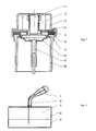
Beschrieben wird ein Einfüllverschluss an insbesondere Brennkraftmaschinen mit einem unteren Fluidbehälter 13 zur Aufnahme eines Fluidvorrats, welches aus einem Gehäuseunterteil und einem stoff- oder formschlüssig mit dem Gehäuseunterteil verbundenen Einfüllrohr 10 gebildet ist und mindestens ein verschließbares Einfüllrohr 10 zur Befüllung des Fluidbehälters 13 mit Fluid aufweist.A filler cap is described in particular with internal combustion engines with a lower fluid container 13 for receiving a fluid reservoir, which is formed from a lower housing part and a material or form-fitting connected to the lower housing filler pipe 10 and at least one closable filler pipe 10 for filling the fluid container 13 with fluid.
Description
Derartige Vorrichtungen sind beispielsweise aus Nutzfahrzeugen, Baumaschinen, Landwirtschaftsmaschinen und anderen motorbetriebenen Geräten wie beispielsweise aus Kraftfahrzeugen bekannt, wo Betriebsmittel wie Kraftstoff und Schmieröl über sogenannte Einfüllstutzen manuell befüllt und nachgefüllt werden können.Such devices are known, for example, from commercial vehicles, construction machines, agricultural machines and other motorized devices such as motor vehicles, where resources such as fuel and lubricating oil can be manually filled and refilled via so-called filler neck.
Ein derartiger Einfüllstutzen ist beispielsweise aus der
Weiter wird in der
In der
Die
Diese marktüblichen Vorrichtungen zum Einfüllen von Betriebsmitteln (Einfüllstutzen) sind aus Wartungsgründen gut zugänglich gestaltet und daher für jede Person frei zugänglich. Daran ist nachteilig, dass die Vorrichtungen nicht abschließbar sind, die Peilstäbe sind nicht für stark gekrümmte Einfüllrohre geeignet.These commercially available devices for filling equipment (filler neck) are designed to be easily accessible for maintenance and therefore freely accessible to any person. This is disadvantageous in that the devices are not lockable, the dipsticks are not suitable for heavily curved filler pipes.
Es ist die Aufgabe der vorliegenden Erfindung, die obigen Nachteile zu vermeiden.It is the object of the present invention to avoid the above disadvantages.
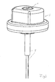
Die Aufgabe wird durch einen abschließbare Einfüllverschluss mit drehbar gelagertem Peilstab zur Füllstandsmessung gelöst, wobei der Betriebsmitteleinfülldeckel abschließbar ist und der am Peilstabkorb angebrachte Peilstab, flach oder rund, drehbar gelagert ist. Der Peilstab kann in verschiedenen Längen ausgeführt sein, um, abhängig von der Länge des Einfüllkanals oder der Ausführung des Fluidraums, dem geforderten Soll-Füllstand zu entsprechen.The task is solved by a lockable filler cap with rotatably mounted dipstick for level measurement, wherein the Betriebsmitteleinfülldeckel lockable and the dipstick basket mounted dipstick, flat or round, is rotatably mounted. The dipstick may be of various lengths to match the required target level, depending on the length of the fill channel or the design of the fluid space.
Eine vorteilhafte Weiterbildung sieht die Abschließbarkeit der Einfüllvorrichtung vor und verhindert das Befüllen von ungeeigneten Materialien und das Entnehmen von Betriebsmitteln durch unbefugte Personen.An advantageous development provides for the lockability of the filling device and prevents the filling of unsuitable materials and the removal of equipment by unauthorized persons.
Weiter ist vorteilhafterweise vorgesehen, dass die drehbare Lagerung des flachen Peilstabs das Blockieren und Verbiegen auch bei stark gekrümmten Einfüllrohren verhindert, da sich beim Einführen in ein stark gekrümmtes Einfüllrohr der Peilstab "aufrichten" und somit das Weiterdrehen des Deckels (3) verhindern würde. Dadurch entstehen Spannungen an der Verbindung zwischen Peilstab und Deckel erst gar nicht.Furthermore, it is advantageously provided that the rotatable mounting of the flat dipstick prevents the blockage and bending even in the case of highly curved filling pipes, since the dipstick will "stand up" during insertion into a strongly curved filler pipe and thus prevent further rotation of the cover (3). As a result, voltages at the connection between the dipstick and the lid do not even arise.
Weitere vorteilhafte Ausgestaltungen sind in den Unteransprüchen enthalten.Further advantageous embodiments are contained in the subclaims.
Weitere Merkmale und Vorteile der vorliegenden Erfindung ergeben sich aus der nachfolgenden Beschreibung von Ausführungsbeispielen unter Bezugnahme auf die beigefügten Figuren. Es zeigen:
- Figur 1
- einen abschließbaren Einfüllverschluss mit drehbarem Peilstab
Figur 2- den Fluidbehälter mit abschließbaren Einfüllverschluss aus
Figur 1 Figur 3- den Deckel mit Schließzylinder und Peilstab aus
Figur 1 Figur 4- den Deckel aus
Figur 1 mit zwei Peilstabkorbbajonettnasen - Figur 5
- den abschließbaren Deckel aus
Figur 1 im unverschlossenen Zustand
- FIG. 1
- a lockable filler cap with rotating dipstick
- FIG. 2
- the fluid container with lockable filler cap off
FIG. 1 - FIG. 3
- The lid with lock cylinder and dipstick
FIG. 1 - FIG. 4
- the lid off
FIG. 1 with two dipstick bayonet noses - FIG. 5
- the lockable lid off
FIG. 1 in unlocked condition
In
Die
Der Fluidbehälter 13 ist zur Aufnahme von Kraftstoff, Öl, Ad-Blue, Wasser, Frostschutz bzw. Kühlmittel geeignet.The
- 11
- Schließzylinderlock cylinder
- 22
- Spannfedertension spring
- 33
- Deckelcover
- 44
- Stützringsupport ring
- 55
- VerschlussblechSealing sheet
- 66
- Ausgleichselementcompensation element
- 77
- Dichtungpoetry
- 88th
- PeilstabkorbPeilstabkorb
- 99
- Peilstabdipstick
- 1010
- Einfüllrohrfiller pipe
- 1111
- Fluidraumfluid space
- 1212
- Iststandactual status
- 1313
- Fluidbehälterfluid container
- 1414
- PeilstabkorbbajonettnasePeilstabkorbbajonettnase
Claims (10)
dadurch gekennzeichnet, dass das verschließbare Einfüllrohr (10) wenigstens einen Deckel (3) aufweist.Filler cap according to claim 1,
characterized in that the closable filler pipe (10) has at least one cover (3).
dadurch gekennzeichnet, dass im Deckel (3) wenigstens ein Schließzylinder angeordnet ist.Filler cap according to claim 1 or 2,
characterized in that in the lid (3) at least one lock cylinder is arranged.
dadurch gekennzeichnet, dass der Deckel (3) wenigstens einen Stützring aufweist.Filler cap according to one or more of the preceding claims,
characterized in that the lid (3) has at least one support ring.
dadurch gekennzeichnet, dass der Deckel (3) wenigstens eine Spannfeder (2) aufweist, die im Wesentlichen konzentrisch um den Schließzylinder (1) herum angeordnet ist.Filler cap according to one or more of the preceding claims,
characterized in that the lid (3) comprises at least one tension spring (2) which is arranged substantially concentrically around the lock cylinder (1).
dadurch gekennzeichnet, dass der Deckel (3) wenigstens ein Verschlussblech (5) aufweist.Filler cap according to one or more of the preceding claims,
characterized in that the lid (3) has at least one closure plate (5).
dadurch gekennzeichnet, dass der Deckel (3) wenigstens einen Peilstabkorb (8) aufweist.Filler cap according to one or more of the preceding claims,
characterized in that the lid (3) has at least one Peilstabkorb (8).
dadurch gekennzeichnet, dass der Deckel (3) wenigstens einen Peilstab (9) aufweist.Filler cap according to one or more of the preceding claims,
characterized in that the lid (3) has at least one dipstick (9).
dadurch gekennzeichnet, dass der Deckel (3) wenigstens eine Dichtung (7) aufweist.Filler cap according to one or more of the preceding claims,
characterized in that the lid (3) has at least one seal (7).
dadurch gekennzeichnet, dass das Einfüllrohr (10) und/oder der Fluidbehälter (13) aus Kunststoff bestehen.Filler cap according to one or more of the preceding claims,
characterized in that the filler pipe (10) and / or the fluid container (13) consist of plastic.
Applications Claiming Priority (1)
| Application Number | Priority Date | Filing Date | Title |
|---|---|---|---|
| DE201310017747 DE102013017747A1 (en) | 2013-10-28 | 2013-10-28 | filler cap |
Publications (3)
| Publication Number | Publication Date |
|---|---|
| EP2865554A2 true EP2865554A2 (en) | 2015-04-29 |
| EP2865554A3 EP2865554A3 (en) | 2015-09-30 |
| EP2865554B1 EP2865554B1 (en) | 2018-12-05 |
Family
ID=51690190
Family Applications (1)
| Application Number | Title | Priority Date | Filing Date |
|---|---|---|---|
| EP14003446.3A Active EP2865554B1 (en) | 2013-10-28 | 2014-10-07 | Fluid tank |
Country Status (2)
| Country | Link |
|---|---|
| EP (1) | EP2865554B1 (en) |
| DE (1) | DE102013017747A1 (en) |
Cited By (1)
| Publication number | Priority date | Publication date | Assignee | Title |
|---|---|---|---|---|
| CN113027632A (en) * | 2021-03-31 | 2021-06-25 | 安徽江淮汽车集团股份有限公司 | Engine cylinder cover shield and vehicle |
Families Citing this family (1)
| Publication number | Priority date | Publication date | Assignee | Title |
|---|---|---|---|---|
| DE102019211995A1 (en) | 2018-09-05 | 2020-03-05 | Zf Friedrichshafen Ag | Gearbox for a motor vehicle, oil filler neck and oil filler and measuring device |
Citations (4)
| Publication number | Priority date | Publication date | Assignee | Title |
|---|---|---|---|---|
| US2953939A (en) | 1956-12-28 | 1960-09-27 | Gen Motors Corp | Transmission |
| US4331185A (en) | 1980-07-14 | 1982-05-25 | Caterpillar Tractor Co. | Transmission filler assembly |
| FR2542037A1 (en) | 1983-03-02 | 1984-09-07 | Juillet Hubert | Service oil kit |
| DE102007026369A1 (en) | 2007-06-06 | 2008-12-11 | GM Global Technology Operations, Inc., Detroit | Device for filling of oil into inner space of machine housing, for example into oil sump of engine housing of combustion engine, has dipstick channel in which oil dipstick is extended from filling opening to oil sump of inner space |
Family Cites Families (8)
| Publication number | Priority date | Publication date | Assignee | Title |
|---|---|---|---|---|
| US3371418A (en) * | 1966-05-18 | 1968-03-05 | Moeller Mfg Co Inc | Oil level testing dip stick with closure |
| DE2930133C2 (en) * | 1979-07-25 | 1982-12-02 | Daimler-Benz Ag, 7000 Stuttgart | Lid for a closure base, in particular a motor vehicle tank |
| FR2704299B1 (en) * | 1993-04-22 | 1995-06-02 | Journee Paul Sa | Arrangement for closing a filling line for a motor vehicle fuel tank. |
| US5485681A (en) * | 1994-06-28 | 1996-01-23 | Moeller Products, Inc. | Swivel type dipstik |
| DE202004017791U1 (en) * | 2004-11-09 | 2006-03-23 | Reutter Metallwarenfabrik Gmbh | Sealing cap and filling nozzle combination for fuel tank of motor vehicle, has filling nozzle with sealing ring, which is inserted into groove of contact surface of nozzle, where outer edge of contact surface is inclined |
| CN101749077B (en) * | 2008-12-04 | 2011-11-02 | 光阳工业股份有限公司 | Engine oil cooling structure of internal combustion engine |
| US8291608B2 (en) * | 2009-01-25 | 2012-10-23 | Kurt Karl Fogle | Engine oil cap protector |
| DE102011117999B4 (en) * | 2011-11-09 | 2013-06-13 | Kautex Textron Gmbh & Co. Kg | Container for a motor vehicle, in particular fuel or auxiliary fluid container for a motor vehicle and method for producing such a container |
-
2013
- 2013-10-28 DE DE201310017747 patent/DE102013017747A1/en not_active Withdrawn
-
2014
- 2014-10-07 EP EP14003446.3A patent/EP2865554B1/en active Active
Patent Citations (4)
| Publication number | Priority date | Publication date | Assignee | Title |
|---|---|---|---|---|
| US2953939A (en) | 1956-12-28 | 1960-09-27 | Gen Motors Corp | Transmission |
| US4331185A (en) | 1980-07-14 | 1982-05-25 | Caterpillar Tractor Co. | Transmission filler assembly |
| FR2542037A1 (en) | 1983-03-02 | 1984-09-07 | Juillet Hubert | Service oil kit |
| DE102007026369A1 (en) | 2007-06-06 | 2008-12-11 | GM Global Technology Operations, Inc., Detroit | Device for filling of oil into inner space of machine housing, for example into oil sump of engine housing of combustion engine, has dipstick channel in which oil dipstick is extended from filling opening to oil sump of inner space |
Cited By (2)
| Publication number | Priority date | Publication date | Assignee | Title |
|---|---|---|---|---|
| CN113027632A (en) * | 2021-03-31 | 2021-06-25 | 安徽江淮汽车集团股份有限公司 | Engine cylinder cover shield and vehicle |
| CN113027632B (en) * | 2021-03-31 | 2022-02-25 | 安徽江淮汽车集团股份有限公司 | Engine cylinder cover shield and vehicle |
Also Published As
| Publication number | Publication date |
|---|---|
| DE102013017747A1 (en) | 2015-04-30 |
| EP2865554B1 (en) | 2018-12-05 |
| EP2865554A3 (en) | 2015-09-30 |
Similar Documents
| Publication | Publication Date | Title |
|---|---|---|
| EP2300256B1 (en) | Insert element for a container suitable for filling with urea at a filling station | |
| EP3234339B1 (en) | Suction device | |
| DE202015007046U1 (en) | Water supply system of a liquid cooling device, pump with water supply system and liquid cooling device with water supply system | |
| EP2331799B1 (en) | Modular tank system for a liquid reducing agent, comprising a bottom element | |
| EP2865554A2 (en) | Filler cap | |
| EP2628937B1 (en) | Cover on the outer circumference of a fuel tank | |
| EP2019079B1 (en) | Automatic fuel nozzle with drip catcher | |
| DE102008039150A1 (en) | Insert element for diesel-fuel container, has tubular retainer provided in container opening, where tubular fitting is held parallel to retainer, and external diameter of tubular retainer is smaller than inner diameter of outlet pipe | |
| DE102005041437A1 (en) | Fueling monitor for tank lorry, has sealing piston closing inlet, when input-side is loaded with pressure below preset pressure limit, and releasing inlet for filling of tank, when input-side is loaded with pressure above limit | |
| DE102014111323A1 (en) | Oil level indicator for a motor | |
| DE102008027462A1 (en) | Insert element for fuel tank of motor vehicle, has inner flank carried on spacer, whose one end is wider in cross-section than standard inner diameter of discharge pipe provided for gas pump nozzle | |
| DE202008010648U1 (en) | Liquid container with air supply | |
| DE102014118702A1 (en) | Crankshaft and crankshaft assembly | |
| DE202019104886U1 (en) | hydrant | |
| DE102011077027B4 (en) | Housing bell with integrated pressure accumulator with flanged lid | |
| DE10109152A1 (en) | Measurement of fluid or loose material level in a container using a capacitive sensor and an alternating voltage supply with the filling material acting as the second capacitor plate so an additional plate is not required | |
| DE102010016220B4 (en) | motor vehicle | |
| DE102004055544B4 (en) | refueling device | |
| DE10341408B3 (en) | Filling cap unit for tank of motor vehicle has closing part held in filling part by locking pins in each guide hole | |
| DE112019005056T5 (en) | Lubrication arrangement and a vehicle with such a lubrication arrangement | |
| DE102013017285B4 (en) | filler cap | |
| EP2884150B1 (en) | Lubrication pump | |
| DE202014100316U1 (en) | Construction of a drinking water tank | |
| DE102015008183A1 (en) | Expansion tank with adapters for a brake fluid reservoir | |
| DE202006013012U1 (en) | Oil tank closure for internal combustion engine of motorcycle, has interlocking unit arranged along fuel dip stick at height such that it is brought into engagement with interlocking shoulder of oil tank formed at ends of filler neck |
Legal Events
| Date | Code | Title | Description |
|---|---|---|---|
| PUAI | Public reference made under article 153(3) epc to a published international application that has entered the european phase |
Free format text: ORIGINAL CODE: 0009012 |
|
| 17P | Request for examination filed |
Effective date: 20141007 |
|
| AK | Designated contracting states |
Kind code of ref document: A2 Designated state(s): AL AT BE BG CH CY CZ DE DK EE ES FI FR GB GR HR HU IE IS IT LI LT LU LV MC MK MT NL NO PL PT RO RS SE SI SK SM TR |
|
| AX | Request for extension of the european patent |
Extension state: BA ME |
|
| PUAL | Search report despatched |
Free format text: ORIGINAL CODE: 0009013 |
|
| AK | Designated contracting states |
Kind code of ref document: A3 Designated state(s): AL AT BE BG CH CY CZ DE DK EE ES FI FR GB GR HR HU IE IS IT LI LT LU LV MC MK MT NL NO PL PT RO RS SE SI SK SM TR |
|
| AX | Request for extension of the european patent |
Extension state: BA ME |
|
| RIC1 | Information provided on ipc code assigned before grant |
Ipc: B60K 15/04 20060101AFI20150825BHEP Ipc: F01M 11/04 20060101ALI20150825BHEP Ipc: B60K 15/03 20060101ALI20150825BHEP Ipc: G01F 23/04 20060101ALI20150825BHEP |
|
| R17P | Request for examination filed (corrected) |
Effective date: 20160303 |
|
| RBV | Designated contracting states (corrected) |
Designated state(s): AL AT BE BG CH CY CZ DE DK EE ES FI FR GB GR HR HU IE IS IT LI LT LU LV MC MK MT NL NO PL PT RO RS SE SI SK SM TR |
|
| STAA | Information on the status of an ep patent application or granted ep patent |
Free format text: STATUS: EXAMINATION IS IN PROGRESS |
|
| 17Q | First examination report despatched |
Effective date: 20161110 |
|
| GRAP | Despatch of communication of intention to grant a patent |
Free format text: ORIGINAL CODE: EPIDOSNIGR1 |
|
| STAA | Information on the status of an ep patent application or granted ep patent |
Free format text: STATUS: GRANT OF PATENT IS INTENDED |
|
| INTG | Intention to grant announced |
Effective date: 20180614 |
|
| GRAS | Grant fee paid |
Free format text: ORIGINAL CODE: EPIDOSNIGR3 |
|
| GRAA | (expected) grant |
Free format text: ORIGINAL CODE: 0009210 |
|
| STAA | Information on the status of an ep patent application or granted ep patent |
Free format text: STATUS: THE PATENT HAS BEEN GRANTED |
|
| AK | Designated contracting states |
Kind code of ref document: B1 Designated state(s): AL AT BE BG CH CY CZ DE DK EE ES FI FR GB GR HR HU IE IS IT LI LT LU LV MC MK MT NL NO PL PT RO RS SE SI SK SM TR |
|
| REG | Reference to a national code |
Ref country code: GB Ref legal event code: FG4D Free format text: NOT ENGLISH |
|
| REG | Reference to a national code |
Ref country code: CH Ref legal event code: EP |
|
| REG | Reference to a national code |
Ref country code: AT Ref legal event code: REF Ref document number: 1072577 Country of ref document: AT Kind code of ref document: T Effective date: 20181215 |
|
| REG | Reference to a national code |
Ref country code: IE Ref legal event code: FG4D Free format text: LANGUAGE OF EP DOCUMENT: GERMAN |
|
| REG | Reference to a national code |
Ref country code: DE Ref legal event code: R096 Ref document number: 502014010242 Country of ref document: DE |
|
| REG | Reference to a national code |
Ref country code: NL Ref legal event code: MP Effective date: 20181205 |
|
| REG | Reference to a national code |
Ref country code: LT Ref legal event code: MG4D |
|
| PG25 | Lapsed in a contracting state [announced via postgrant information from national office to epo] |
Ref country code: FI Free format text: LAPSE BECAUSE OF FAILURE TO SUBMIT A TRANSLATION OF THE DESCRIPTION OR TO PAY THE FEE WITHIN THE PRESCRIBED TIME-LIMIT Effective date: 20181205 Ref country code: LT Free format text: LAPSE BECAUSE OF FAILURE TO SUBMIT A TRANSLATION OF THE DESCRIPTION OR TO PAY THE FEE WITHIN THE PRESCRIBED TIME-LIMIT Effective date: 20181205 Ref country code: HR Free format text: LAPSE BECAUSE OF FAILURE TO SUBMIT A TRANSLATION OF THE DESCRIPTION OR TO PAY THE FEE WITHIN THE PRESCRIBED TIME-LIMIT Effective date: 20181205 Ref country code: BG Free format text: LAPSE BECAUSE OF FAILURE TO SUBMIT A TRANSLATION OF THE DESCRIPTION OR TO PAY THE FEE WITHIN THE PRESCRIBED TIME-LIMIT Effective date: 20190305 Ref country code: ES Free format text: LAPSE BECAUSE OF FAILURE TO SUBMIT A TRANSLATION OF THE DESCRIPTION OR TO PAY THE FEE WITHIN THE PRESCRIBED TIME-LIMIT Effective date: 20181205 Ref country code: LV Free format text: LAPSE BECAUSE OF FAILURE TO SUBMIT A TRANSLATION OF THE DESCRIPTION OR TO PAY THE FEE WITHIN THE PRESCRIBED TIME-LIMIT Effective date: 20181205 Ref country code: NO Free format text: LAPSE BECAUSE OF FAILURE TO SUBMIT A TRANSLATION OF THE DESCRIPTION OR TO PAY THE FEE WITHIN THE PRESCRIBED TIME-LIMIT Effective date: 20190305 |
|
| PG25 | Lapsed in a contracting state [announced via postgrant information from national office to epo] |
Ref country code: AL Free format text: LAPSE BECAUSE OF FAILURE TO SUBMIT A TRANSLATION OF THE DESCRIPTION OR TO PAY THE FEE WITHIN THE PRESCRIBED TIME-LIMIT Effective date: 20181205 Ref country code: RS Free format text: LAPSE BECAUSE OF FAILURE TO SUBMIT A TRANSLATION OF THE DESCRIPTION OR TO PAY THE FEE WITHIN THE PRESCRIBED TIME-LIMIT Effective date: 20181205 Ref country code: GR Free format text: LAPSE BECAUSE OF FAILURE TO SUBMIT A TRANSLATION OF THE DESCRIPTION OR TO PAY THE FEE WITHIN THE PRESCRIBED TIME-LIMIT Effective date: 20190306 Ref country code: SE Free format text: LAPSE BECAUSE OF FAILURE TO SUBMIT A TRANSLATION OF THE DESCRIPTION OR TO PAY THE FEE WITHIN THE PRESCRIBED TIME-LIMIT Effective date: 20181205 |
|
| PG25 | Lapsed in a contracting state [announced via postgrant information from national office to epo] |
Ref country code: NL Free format text: LAPSE BECAUSE OF FAILURE TO SUBMIT A TRANSLATION OF THE DESCRIPTION OR TO PAY THE FEE WITHIN THE PRESCRIBED TIME-LIMIT Effective date: 20181205 |
|
| PG25 | Lapsed in a contracting state [announced via postgrant information from national office to epo] |
Ref country code: IT Free format text: LAPSE BECAUSE OF FAILURE TO SUBMIT A TRANSLATION OF THE DESCRIPTION OR TO PAY THE FEE WITHIN THE PRESCRIBED TIME-LIMIT Effective date: 20181205 Ref country code: CZ Free format text: LAPSE BECAUSE OF FAILURE TO SUBMIT A TRANSLATION OF THE DESCRIPTION OR TO PAY THE FEE WITHIN THE PRESCRIBED TIME-LIMIT Effective date: 20181205 Ref country code: PT Free format text: LAPSE BECAUSE OF FAILURE TO SUBMIT A TRANSLATION OF THE DESCRIPTION OR TO PAY THE FEE WITHIN THE PRESCRIBED TIME-LIMIT Effective date: 20190405 Ref country code: PL Free format text: LAPSE BECAUSE OF FAILURE TO SUBMIT A TRANSLATION OF THE DESCRIPTION OR TO PAY THE FEE WITHIN THE PRESCRIBED TIME-LIMIT Effective date: 20181205 |
|
| PG25 | Lapsed in a contracting state [announced via postgrant information from national office to epo] |
Ref country code: SK Free format text: LAPSE BECAUSE OF FAILURE TO SUBMIT A TRANSLATION OF THE DESCRIPTION OR TO PAY THE FEE WITHIN THE PRESCRIBED TIME-LIMIT Effective date: 20181205 Ref country code: RO Free format text: LAPSE BECAUSE OF FAILURE TO SUBMIT A TRANSLATION OF THE DESCRIPTION OR TO PAY THE FEE WITHIN THE PRESCRIBED TIME-LIMIT Effective date: 20181205 Ref country code: IS Free format text: LAPSE BECAUSE OF FAILURE TO SUBMIT A TRANSLATION OF THE DESCRIPTION OR TO PAY THE FEE WITHIN THE PRESCRIBED TIME-LIMIT Effective date: 20190405 Ref country code: EE Free format text: LAPSE BECAUSE OF FAILURE TO SUBMIT A TRANSLATION OF THE DESCRIPTION OR TO PAY THE FEE WITHIN THE PRESCRIBED TIME-LIMIT Effective date: 20181205 Ref country code: SM Free format text: LAPSE BECAUSE OF FAILURE TO SUBMIT A TRANSLATION OF THE DESCRIPTION OR TO PAY THE FEE WITHIN THE PRESCRIBED TIME-LIMIT Effective date: 20181205 |
|
| REG | Reference to a national code |
Ref country code: DE Ref legal event code: R097 Ref document number: 502014010242 Country of ref document: DE |
|
| PLBE | No opposition filed within time limit |
Free format text: ORIGINAL CODE: 0009261 |
|
| STAA | Information on the status of an ep patent application or granted ep patent |
Free format text: STATUS: NO OPPOSITION FILED WITHIN TIME LIMIT |
|
| PG25 | Lapsed in a contracting state [announced via postgrant information from national office to epo] |
Ref country code: DK Free format text: LAPSE BECAUSE OF FAILURE TO SUBMIT A TRANSLATION OF THE DESCRIPTION OR TO PAY THE FEE WITHIN THE PRESCRIBED TIME-LIMIT Effective date: 20181205 Ref country code: SI Free format text: LAPSE BECAUSE OF FAILURE TO SUBMIT A TRANSLATION OF THE DESCRIPTION OR TO PAY THE FEE WITHIN THE PRESCRIBED TIME-LIMIT Effective date: 20181205 |
|
| 26N | No opposition filed |
Effective date: 20190906 |
|
| PG25 | Lapsed in a contracting state [announced via postgrant information from national office to epo] |
Ref country code: TR Free format text: LAPSE BECAUSE OF FAILURE TO SUBMIT A TRANSLATION OF THE DESCRIPTION OR TO PAY THE FEE WITHIN THE PRESCRIBED TIME-LIMIT Effective date: 20181205 |
|
| PG25 | Lapsed in a contracting state [announced via postgrant information from national office to epo] |
Ref country code: MC Free format text: LAPSE BECAUSE OF FAILURE TO SUBMIT A TRANSLATION OF THE DESCRIPTION OR TO PAY THE FEE WITHIN THE PRESCRIBED TIME-LIMIT Effective date: 20181205 |
|
| REG | Reference to a national code |
Ref country code: CH Ref legal event code: PL |
|
| PG25 | Lapsed in a contracting state [announced via postgrant information from national office to epo] |
Ref country code: LI Free format text: LAPSE BECAUSE OF NON-PAYMENT OF DUE FEES Effective date: 20191031 Ref country code: CH Free format text: LAPSE BECAUSE OF NON-PAYMENT OF DUE FEES Effective date: 20191031 Ref country code: LU Free format text: LAPSE BECAUSE OF NON-PAYMENT OF DUE FEES Effective date: 20191007 |
|
| REG | Reference to a national code |
Ref country code: BE Ref legal event code: MM Effective date: 20191031 |
|
| PG25 | Lapsed in a contracting state [announced via postgrant information from national office to epo] |
Ref country code: BE Free format text: LAPSE BECAUSE OF NON-PAYMENT OF DUE FEES Effective date: 20191031 |
|
| PG25 | Lapsed in a contracting state [announced via postgrant information from national office to epo] |
Ref country code: IE Free format text: LAPSE BECAUSE OF NON-PAYMENT OF DUE FEES Effective date: 20191007 |
|
| REG | Reference to a national code |
Ref country code: AT Ref legal event code: MM01 Ref document number: 1072577 Country of ref document: AT Kind code of ref document: T Effective date: 20191007 |
|
| PG25 | Lapsed in a contracting state [announced via postgrant information from national office to epo] |
Ref country code: AT Free format text: LAPSE BECAUSE OF NON-PAYMENT OF DUE FEES Effective date: 20191007 |
|
| PG25 | Lapsed in a contracting state [announced via postgrant information from national office to epo] |
Ref country code: CY Free format text: LAPSE BECAUSE OF FAILURE TO SUBMIT A TRANSLATION OF THE DESCRIPTION OR TO PAY THE FEE WITHIN THE PRESCRIBED TIME-LIMIT Effective date: 20181205 |
|
| PG25 | Lapsed in a contracting state [announced via postgrant information from national office to epo] |
Ref country code: MT Free format text: LAPSE BECAUSE OF FAILURE TO SUBMIT A TRANSLATION OF THE DESCRIPTION OR TO PAY THE FEE WITHIN THE PRESCRIBED TIME-LIMIT Effective date: 20181205 Ref country code: HU Free format text: LAPSE BECAUSE OF FAILURE TO SUBMIT A TRANSLATION OF THE DESCRIPTION OR TO PAY THE FEE WITHIN THE PRESCRIBED TIME-LIMIT; INVALID AB INITIO Effective date: 20141007 |
|
| PG25 | Lapsed in a contracting state [announced via postgrant information from national office to epo] |
Ref country code: MK Free format text: LAPSE BECAUSE OF FAILURE TO SUBMIT A TRANSLATION OF THE DESCRIPTION OR TO PAY THE FEE WITHIN THE PRESCRIBED TIME-LIMIT Effective date: 20181205 |
|
| PGFP | Annual fee paid to national office [announced via postgrant information from national office to epo] |
Ref country code: GB Payment date: 20231020 Year of fee payment: 10 |
|
| PGFP | Annual fee paid to national office [announced via postgrant information from national office to epo] |
Ref country code: FR Payment date: 20231025 Year of fee payment: 10 Ref country code: DE Payment date: 20231018 Year of fee payment: 10 |