EP2863533A2 - Resonant inverter - Google Patents
Resonant inverter Download PDFInfo
- Publication number
- EP2863533A2 EP2863533A2 EP20140185720 EP14185720A EP2863533A2 EP 2863533 A2 EP2863533 A2 EP 2863533A2 EP 20140185720 EP20140185720 EP 20140185720 EP 14185720 A EP14185720 A EP 14185720A EP 2863533 A2 EP2863533 A2 EP 2863533A2
- Authority
- EP
- European Patent Office
- Prior art keywords
- gap
- core half
- transformer
- electrosurgical generator
- secondary winding
- Prior art date
- Legal status (The legal status is an assumption and is not a legal conclusion. Google has not performed a legal analysis and makes no representation as to the accuracy of the status listed.)
- Withdrawn
Links
Images


Classifications
-
- A—HUMAN NECESSITIES
- A61—MEDICAL OR VETERINARY SCIENCE; HYGIENE
- A61B—DIAGNOSIS; SURGERY; IDENTIFICATION
- A61B18/00—Surgical instruments, devices or methods for transferring non-mechanical forms of energy to or from the body
- A61B18/04—Surgical instruments, devices or methods for transferring non-mechanical forms of energy to or from the body by heating
- A61B18/12—Surgical instruments, devices or methods for transferring non-mechanical forms of energy to or from the body by heating by passing a current through the tissue to be heated, e.g. high-frequency current
- A61B18/1206—Generators therefor
-
- H—ELECTRICITY
- H01—ELECTRIC ELEMENTS
- H01F—MAGNETS; INDUCTANCES; TRANSFORMERS; SELECTION OF MATERIALS FOR THEIR MAGNETIC PROPERTIES
- H01F27/00—Details of transformers or inductances, in general
- H01F27/006—Details of transformers or inductances, in general with special arrangement or spacing of turns of the winding(s), e.g. to produce desired self-resonance
-
- H—ELECTRICITY
- H02—GENERATION; CONVERSION OR DISTRIBUTION OF ELECTRIC POWER
- H02M—APPARATUS FOR CONVERSION BETWEEN AC AND AC, BETWEEN AC AND DC, OR BETWEEN DC AND DC, AND FOR USE WITH MAINS OR SIMILAR POWER SUPPLY SYSTEMS; CONVERSION OF DC OR AC INPUT POWER INTO SURGE OUTPUT POWER; CONTROL OR REGULATION THEREOF
- H02M7/00—Conversion of ac power input into dc power output; Conversion of dc power input into ac power output
- H02M7/42—Conversion of dc power input into ac power output without possibility of reversal
- H02M7/44—Conversion of dc power input into ac power output without possibility of reversal by static converters
- H02M7/48—Conversion of dc power input into ac power output without possibility of reversal by static converters using discharge tubes with control electrode or semiconductor devices with control electrode
- H02M7/53—Conversion of dc power input into ac power output without possibility of reversal by static converters using discharge tubes with control electrode or semiconductor devices with control electrode using devices of a triode or transistor type requiring continuous application of a control signal
- H02M7/537—Conversion of dc power input into ac power output without possibility of reversal by static converters using discharge tubes with control electrode or semiconductor devices with control electrode using devices of a triode or transistor type requiring continuous application of a control signal using semiconductor devices only, e.g. single switched pulse inverters
- H02M7/5387—Conversion of dc power input into ac power output without possibility of reversal by static converters using discharge tubes with control electrode or semiconductor devices with control electrode using devices of a triode or transistor type requiring continuous application of a control signal using semiconductor devices only, e.g. single switched pulse inverters in a bridge configuration
- H02M7/53871—Conversion of dc power input into ac power output without possibility of reversal by static converters using discharge tubes with control electrode or semiconductor devices with control electrode using devices of a triode or transistor type requiring continuous application of a control signal using semiconductor devices only, e.g. single switched pulse inverters in a bridge configuration with automatic control of output voltage or current
-
- A—HUMAN NECESSITIES
- A61—MEDICAL OR VETERINARY SCIENCE; HYGIENE
- A61B—DIAGNOSIS; SURGERY; IDENTIFICATION
- A61B18/00—Surgical instruments, devices or methods for transferring non-mechanical forms of energy to or from the body
- A61B18/04—Surgical instruments, devices or methods for transferring non-mechanical forms of energy to or from the body by heating
- A61B18/12—Surgical instruments, devices or methods for transferring non-mechanical forms of energy to or from the body by heating by passing a current through the tissue to be heated, e.g. high-frequency current
- A61B18/1206—Generators therefor
- A61B2018/1286—Generators therefor having a specific transformer
-
- H—ELECTRICITY
- H02—GENERATION; CONVERSION OR DISTRIBUTION OF ELECTRIC POWER
- H02M—APPARATUS FOR CONVERSION BETWEEN AC AND AC, BETWEEN AC AND DC, OR BETWEEN DC AND DC, AND FOR USE WITH MAINS OR SIMILAR POWER SUPPLY SYSTEMS; CONVERSION OF DC OR AC INPUT POWER INTO SURGE OUTPUT POWER; CONTROL OR REGULATION THEREOF
- H02M7/00—Conversion of ac power input into dc power output; Conversion of dc power input into ac power output
- H02M7/42—Conversion of dc power input into ac power output without possibility of reversal
- H02M7/44—Conversion of dc power input into ac power output without possibility of reversal by static converters
- H02M7/48—Conversion of dc power input into ac power output without possibility of reversal by static converters using discharge tubes with control electrode or semiconductor devices with control electrode
- H02M7/4815—Resonant converters
-
- Y—GENERAL TAGGING OF NEW TECHNOLOGICAL DEVELOPMENTS; GENERAL TAGGING OF CROSS-SECTIONAL TECHNOLOGIES SPANNING OVER SEVERAL SECTIONS OF THE IPC; TECHNICAL SUBJECTS COVERED BY FORMER USPC CROSS-REFERENCE ART COLLECTIONS [XRACs] AND DIGESTS
- Y02—TECHNOLOGIES OR APPLICATIONS FOR MITIGATION OR ADAPTATION AGAINST CLIMATE CHANGE
- Y02B—CLIMATE CHANGE MITIGATION TECHNOLOGIES RELATED TO BUILDINGS, e.g. HOUSING, HOUSE APPLIANCES OR RELATED END-USER APPLICATIONS
- Y02B70/00—Technologies for an efficient end-user side electric power management and consumption
- Y02B70/10—Technologies improving the efficiency by using switched-mode power supplies [SMPS], i.e. efficient power electronics conversion e.g. power factor correction or reduction of losses in power supplies or efficient standby modes
Definitions
- the present disclosure relates to radiofrequency amplifiers that use phase-shifted full bridge resonant inverters. Particularly, the present disclosure is directed to reducing the cost and complexity of the resonant inverters.
- Electrosurgery involves application of high radio frequency electrical current to a surgical site to cut, ablate, coagulate or seal tissue.
- a source or active electrode delivers radio frequency energy from the electrosurgical generator to the tissue and a return electrode carries the current back to the generator.
- the source electrode is typically part of the surgical instrument held by the surgeon and applied to the tissue to be treated and the return electrode is placed remotely from the active electrode to carry the current back to the generator.
- bipolar electrosurgery one of the electrodes of the hand-held instrument functions as the active electrode and the other as the return electrode.
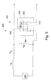
- FIG. 1 is an example of a prior art electrosurgical generator that uses a phase-shifted full bridge resonant inverter to generate the electrosurgical energy needed to perform the electrosurgical procedure.
- the generator 100 includes a resonant inverter 102 and a pulse width modulation (PWM) controller 108.
- the resonant inverter 102 includes an H-bridge 104 an LCLC tank 106.
- the tank 106 includes a series inductor, a series capacitor, a parallel inductor, and a parallel capacitor. Because of the number of components in the tank 106, the cost and complexity of the resonant inverter is increased.
- the term “generator” may refer to a device capable of providing energy. Such device may include a power source and an electrical circuit capable of modifying the energy outputted by the power source to output energy having a desired intensity, frequency, and/or waveform.
- the systems described herein may also utilize one or more controllers to receive various information and transform the received information to generate an output.
- the controller may include any type of computing device, computational circuit, or any type of processor or processing circuit capable of executing a series of instructions that are stored in a memory.
- the controller may include multiple processors and/or multicore central processing units (CPUs) and may include any type of processor, such as a microprocessor, digital signal processor, microcontroller, or the like.
- the controller may also include a memory to store data and/or algorithms to perform a series of instructions.
- any of the herein described data and/or algorithms may be contained on one or more machine-readable media or memory.
- the term "memory" may include a mechanism that provides (e.g., stores and/or transmits) information in a form readable by a machine such a processor, computer, or a digital processing device.
- a memory may include a read only memory (ROM), random access memory (RAM), magnetic disk storage media, optical storage media, flash memory devices, or any other volatile or non-volatile memory storage device.
- Code or instructions contained thereon can be represented by carrier wave signals, infrared signals, digital signals, and by other like signals.
- an electrosurgical generator in an aspect of the present disclosure, includes a tank configured to output energy and an H-bridge configured to drive the tank.
- the generator also includes a transformer.
- the transformer has a first core half, a second core half, a primary winding, and a secondary winding having a number of turns, wherein each turn is separated by a gap.
- the transformer is configured to provide a parallel capacitance based on the gap.
- an electrosurgical generator in another aspect of the present disclosure, includes a tank configured to output energy and an H-bridge configured to drive the tank.
- the generator also includes a transformer.
- the transformer includes a first core half, a second core half separated from the first core half by a first gap, a primary winding, and a secondary winding having a number of turns wherein each turn is separated by a second gap.
- the transformer is configured to provide a magnetizing inductance based on the first gap and a parallel capacitance based on the second gap.
- an electrosurgical generator in yet another aspect of the present disclosure, includes a tank configured to output energy and an H-bridge configured to drive the tank.
- the generator also includes a transformer.
- the transformer includes a first core half, a second core half separated from the first core half by a first gap, a primary winding, and a secondary winding separated from the primary winding by a second gap.
- the secondary winding having a number of turns wherein each turn is separated by a third gap.
- the transformer is configured to provide a magnetizing inductance based on the first gap, a leakage inductance based on the second gap, and a parallel capacitance based on the third gap.
- an electrosurgical generator comprising: a tank configured to output energy; an H-bridge configured to drive the tank; and a transformer including: a first core half; a second core half separated from the first core half by a gap; a primary winding; and a secondary winding, wherein the transformer is configured to provide a magnetizing inductance based on the gap.
- an electrosurgical generator comprising: a tank configured to output energy; an H-bridge configured to drive the tank; and a transformer including: a first core half; a second core half; a primary winding; and a secondary winding separated from the primary winding by a gap, wherein the transformer is configured to provide a leakage inductance based on the gap.
- the electrosurgical generators include a bobbin coupled to the first core half and the second core half. Both the primary winding and the secondary winding are disposed on the bobbin.
- the present disclosure is directed to an electrosurgical generator that employs a phase-shifted full bridge resonant inverter having an LCLC tank topology and an H-bridge.
- the number of components in the LCLC tank may be reduced by incorporating the components into the patient isolation transformer of the LCLC tank.
- Transformer 200 includes a first core half 202 and a second core half 204 that are spaced apart by a gap "L.
- First core half 202 and second core half 204 may be an industry standard core PQ2625 FERROXCUBE ® ferrite core available from FERROXCUBE (formerly a Philips Components company part of the Yageo Corporation).
- First core half 202 and second core half 204 have respective central members 206 and 208 that are configured to receive a bobbin 210.
- Bobbin 210 includes a primary winding 212 and a secondary winding 214. The primary winding 212 and the secondary winding 214 are separated by a gap "D".
- the primary winding 212 and the secondary winding 214 are fabricated from a wire wrapped around the bobbin 210.
- the turns of the wire are separated by a gap "X".
- the gaps "L”, “D”, and “X” are used to incorporate inductors and capacitors into the design of the transformer to reduce the number of components in the resonant inverter.
- gap “L” may be used to incorporate a magnetizing inductance
- gap “D” may be used to incorporate a leakage inductance
- gap "X” may be used to incorporate a parallel capacitance.
- Figures 3-5 depict various resonant inverters according to embodiments of the present disclosure.
- the resonant inverters include a RF source 250 to drive a tank.
- RF source 250 may be similar to H-bridge 104 as shown in Figure 1 .
- the resonant inverter 300 includes a series inductor L S , a series Capacitor C S , and a parallel inductor L M .
- the resonant inverter also includes a transformer 302.
- the transformer 302 includes a first core half 304 and a second core half 306 that abuts the first core half 304. Thus, there is no gap "L" and, as such, the transformer 302 does not incorporate a magnetizing inductance.
- the transformer 302 also includes a primary winding 308 and a secondary winding 310 wrapped around bobbin 312.
- the gap "D" between the primary winding 308 and the secondary winding 310 is negligible. Accordingly, the transformer 302 does not incorporate a leakage inductance because the gap "D" is negligible. In the primary winding 308, the gap between turns is arbitrarily large. As such, the primary winding 308 does not incorporate a parallel capacitance on the primary side of the transformer 302.
- the secondary winding 310 includes a gap "X" between turns of the secondary winding 310 thus incorporating the parallel capacitor C P of Figure 1 on the secondary side of the transformer 302 and reducing the number of discrete components needed in the resonant inverter 300.
- the parallel capacitance is determined based on the gap "X", the dielectric material used in the insulation of the wire that forms the secondary winding 310, and the surface area between turns of the secondary winding 310.
- the resonant inverter 400 includes a series inductor L S and a series Capacitor C S .
- the resonant inverter also includes a transformer 402.
- the transformer 302 includes a first core half 404 and a second core half 406 that are separated by a gap "L". Gap "L" determines a magnetizing inductance thus incorporating the parallel inductor L M of Figure 1 and reducing the number of discrete components needed in the resonant inverter 400.
- the transformer 402 also includes a primary winding 408 and a secondary winding 410 wrapped around bobbin 412.
- the gap "D" between the primary winding 408 and the secondary winding 410 is negligible. Accordingly, the transformer 402 does not incorporate a leakage inductance because the gap "D" is negligible.
- the gap between turns is in the primary winding 408 is arbitrarily large and the secondary winding 410 includes a gap "X" between turns of the secondary winding 410 thus incorporating a parallel capacitance on the secondary side of the transformer 402.
- the resonant inverter 500 includes a series capacitor C S and a transformer 502. Similar to transformer 402, the transformer 502 includes a gap "L between first core half 504 and second core half 506 to include a magnetizing inductance and a gap "X" between turns of a secondary winding 510 to include a parallel capacitance on the secondary side of the transformer 502. The transformer 502 also includes a gap "D" between a primary winding 508 and the secondary winding 510.
- the distance "D” determines a leakage inductance thus incorporating the series inductor L S of Figure 1 and reducing the number of discrete components needed in the resonant inverter 502.
- the relationship between the distance "D” and the leakage inductance L S is determined empirically.
- the resonant inverter 502 when compared to the resonant inverter 102 of Figure 1 which needs five discrete components in the tank 106, the resonant inverter 502 only needs two components in the tank thereby reducing the cost of the resonant inverter as well as the complexity.
- the resonant inverters described in Figures 3-5 can be included in an electrosurgical generator in accordance with embodiments of the present disclosure.
- the generator includes suitable input controls (e.g., buttons, activators, switches, touch screen, etc.) for controlling the generator.
- the generator may include one or more display screens (not shown) for providing the user with variety of output information (e.g., intensity settings, treatment complete indicators, etc.).
- the controls allow the user to adjust power of the RF energy, waveform, as well as the level of maximum arc energy allowed which varies depending on desired tissue effects and other parameters to achieve the desired waveform suitable for a particular task (e.g., coagulating, tissue sealing, intensity setting, etc.).
- An instrument that may be connected to the generator may also include a plurality of input controls that may be redundant with certain input controls of the generator. Placing the input controls at the instrument allows for easier and faster modification of RF energy parameters during the surgical procedure without requiring interaction with the generator.
- the generator may include a plurality of connectors to accommodate various types of electrosurgical instruments. Further, the generator may operate in monopolar or bipolar modes by including a switching mechanism (e.g., relays) to switch the supply of RF energy between the connectors.
- a switching mechanism e.g., relays
- the transformer may be designed to replace any of the discrete components in multiple combinations.
- the transformer may be used to replace, the series inductor, the parallel inductor, the parallel capacitor, the series inductor and the parallel inductor, the series inductor and the parallel capacitor, the parallel inductor and the parallel capacitor, or all three components.
Landscapes
- Engineering & Computer Science (AREA)
- Power Engineering (AREA)
- Health & Medical Sciences (AREA)
- Surgery (AREA)
- Life Sciences & Earth Sciences (AREA)
- Biomedical Technology (AREA)
- Animal Behavior & Ethology (AREA)
- Nuclear Medicine, Radiotherapy & Molecular Imaging (AREA)
- Physics & Mathematics (AREA)
- Heart & Thoracic Surgery (AREA)
- Medical Informatics (AREA)
- Molecular Biology (AREA)
- Otolaryngology (AREA)
- General Health & Medical Sciences (AREA)
- Public Health (AREA)
- Veterinary Medicine (AREA)
- Plasma & Fusion (AREA)
- Inverter Devices (AREA)
- Surgical Instruments (AREA)
Abstract
Description
- The present disclosure relates to radiofrequency amplifiers that use phase-shifted full bridge resonant inverters. Particularly, the present disclosure is directed to reducing the cost and complexity of the resonant inverters.
- Energy-based tissue treatment is well known in the art. Various types of energy (e.g., electrical, ultrasonic, microwave, cryogenic, thermal, laser, etc.) are applied to tissue to achieve a desired result. Electrosurgery involves application of high radio frequency electrical current to a surgical site to cut, ablate, coagulate or seal tissue. A source or active electrode delivers radio frequency energy from the electrosurgical generator to the tissue and a return electrode carries the current back to the generator. In monopolar electrosurgery, the source electrode is typically part of the surgical instrument held by the surgeon and applied to the tissue to be treated and the return electrode is placed remotely from the active electrode to carry the current back to the generator. In bipolar electrosurgery, one of the electrodes of the hand-held instrument functions as the active electrode and the other as the return electrode.
-
Figure 1 is an example of a prior art electrosurgical generator that uses a phase-shifted full bridge resonant inverter to generate the electrosurgical energy needed to perform the electrosurgical procedure. Thegenerator 100 includes aresonant inverter 102 and a pulse width modulation (PWM)controller 108. Theresonant inverter 102 includes an H-bridge 104 anLCLC tank 106. Thetank 106 includes a series inductor, a series capacitor, a parallel inductor, and a parallel capacitor. Because of the number of components in thetank 106, the cost and complexity of the resonant inverter is increased. - This description may use the phrases "in an embodiment," "in embodiments," "in some embodiments," or "in other embodiments," which may each refer to one or more of the same or different embodiments in accordance with the present disclosure. As used herein, the term "generator" may refer to a device capable of providing energy. Such device may include a power source and an electrical circuit capable of modifying the energy outputted by the power source to output energy having a desired intensity, frequency, and/or waveform.
- The systems described herein may also utilize one or more controllers to receive various information and transform the received information to generate an output. The controller may include any type of computing device, computational circuit, or any type of processor or processing circuit capable of executing a series of instructions that are stored in a memory. The controller may include multiple processors and/or multicore central processing units (CPUs) and may include any type of processor, such as a microprocessor, digital signal processor, microcontroller, or the like. The controller may also include a memory to store data and/or algorithms to perform a series of instructions.
- Any of the herein described data and/or algorithms may be contained on one or more machine-readable media or memory. The term "memory" may include a mechanism that provides (e.g., stores and/or transmits) information in a form readable by a machine such a processor, computer, or a digital processing device. For example, a memory may include a read only memory (ROM), random access memory (RAM), magnetic disk storage media, optical storage media, flash memory devices, or any other volatile or non-volatile memory storage device. Code or instructions contained thereon can be represented by carrier wave signals, infrared signals, digital signals, and by other like signals.
- In an aspect of the present disclosure, an electrosurgical generator includes a tank configured to output energy and an H-bridge configured to drive the tank. The generator also includes a transformer. The transformer has a first core half, a second core half, a primary winding, and a secondary winding having a number of turns, wherein each turn is separated by a gap. The transformer is configured to provide a parallel capacitance based on the gap.
- In another aspect of the present disclosure, an electrosurgical generator includes a tank configured to output energy and an H-bridge configured to drive the tank. The generator also includes a transformer. The transformer includes a first core half, a second core half separated from the first core half by a first gap, a primary winding, and a secondary winding having a number of turns wherein each turn is separated by a second gap. The transformer is configured to provide a magnetizing inductance based on the first gap and a parallel capacitance based on the second gap.
- In yet another aspect of the present disclosure, an electrosurgical generator includes a tank configured to output energy and an H-bridge configured to drive the tank. The generator also includes a transformer. The transformer includes a first core half, a second core half separated from the first core half by a first gap, a primary winding, and a secondary winding separated from the primary winding by a second gap. The secondary winding having a number of turns wherein each turn is separated by a third gap. The transformer is configured to provide a magnetizing inductance based on the first gap, a leakage inductance based on the second gap, and a parallel capacitance based on the third gap.
- In another aspect of the present invention, there is provided an electrosurgical generator comprising: a tank configured to output energy; an H-bridge configured to drive the tank; and a transformer including: a first core half; a second core half separated from the first core half by a gap; a primary winding; and a secondary winding, wherein the transformer is configured to provide a magnetizing inductance based on the gap.
- In another aspect of the present invention, there is provided an electrosurgical generator comprising: a tank configured to output energy; an H-bridge configured to drive the tank; and a transformer including: a first core half; a second core half; a primary winding; and a secondary winding separated from the primary winding by a gap, wherein the transformer is configured to provide a leakage inductance based on the gap.
- In the aspects described above, the electrosurgical generators include a bobbin coupled to the first core half and the second core half. Both the primary winding and the secondary winding are disposed on the bobbin.
- The above and other aspects, features, and advantages of the present disclosure will become more apparent in light of the following detailed description when taken in conjunction with the accompanying drawings in which:
-
Figure 1 is a schematic illustration of a prior art electrosurgical generator; -
Figure 2 is an illustration of a transformer for use in the embodiments of the present disclosure; -
Figure 3 is a schematic illustration of a resonant inverter for an electrosurgical generator in accordance with an embodiment of the present disclosure; and -
Figure 4 is a schematic illustration of a resonant inverter for an electrosurgical generator in accordance with another embodiment of the present disclosure; and -
Figure 5 is a schematic illustration of a resonant inverter for an electrosurgical generator in accordance with yet another embodiment of the present disclosure. - Particular embodiments of the present disclosure are described hereinbelow with reference to the accompanying drawings; however, it is to be understood that the disclosed embodiments are merely examples of the disclosure and may be embodied in various forms. Well-known functions or constructions are not described in detail to avoid obscuring the present disclosure in unnecessary detail. Therefore, specific structural and functional details disclosed herein are not to be interpreted as limiting, but merely as a basis for the claims and as a representative basis for teaching one skilled in the art to variously employ the present disclosure in virtually any appropriately detailed structure. Like reference numerals may refer to similar or identical elements throughout the description of the figures.
- The present disclosure is directed to an electrosurgical generator that employs a phase-shifted full bridge resonant inverter having an LCLC tank topology and an H-bridge. In embodiments of the present disclosure, the number of components in the LCLC tank may be reduced by incorporating the components into the patient isolation transformer of the LCLC tank.
- Turning to
Figure 2 , a patient isolation transformer for use in the embodiments described herein is shown generally as 200. Transformer 200 includes afirst core half 202 and asecond core half 204 that are spaced apart by a gap "L.First core half 202 andsecond core half 204 may be an industry standard core PQ2625 FERROXCUBE® ferrite core available from FERROXCUBE (formerly a Philips Components company part of the Yageo Corporation).First core half 202 andsecond core half 204 have respectivecentral members bobbin 210. Bobbin 210 includes aprimary winding 212 and asecondary winding 214. Theprimary winding 212 and thesecondary winding 214 are separated by a gap "D". The primary winding 212 and the secondary winding 214 are fabricated from a wire wrapped around thebobbin 210. In the secondary winding 214, the turns of the wire are separated by a gap "X". As will be described below, the gaps "L", "D", and "X" are used to incorporate inductors and capacitors into the design of the transformer to reduce the number of components in the resonant inverter. For example, gap "L" may be used to incorporate a magnetizing inductance, gap "D" may be used to incorporate a leakage inductance, and gap "X" may be used to incorporate a parallel capacitance. -
Figures 3-5 depict various resonant inverters according to embodiments of the present disclosure. As shown inFigures 3-5 , the resonant inverters include aRF source 250 to drive a tank.RF source 250 may be similar to H-bridge 104 as shown inFigure 1 . - Turning to
Figure 3 , a resonant inverter in accordance with an embodiment of the present disclosure is shown generally as 300. Theresonant inverter 300 includes a series inductor LS, a series Capacitor CS, and a parallel inductor LM. The resonant inverter also includes atransformer 302. Thetransformer 302 includes a firstcore half 304 and a secondcore half 306 that abuts the firstcore half 304. Thus, there is no gap "L" and, as such, thetransformer 302 does not incorporate a magnetizing inductance. Thetransformer 302 also includes a primary winding 308 and a secondary winding 310 wrapped aroundbobbin 312. The gap "D" between the primary winding 308 and the secondary winding 310 is negligible. Accordingly, thetransformer 302 does not incorporate a leakage inductance because the gap "D" is negligible. In the primary winding 308, the gap between turns is arbitrarily large. As such, the primary winding 308 does not incorporate a parallel capacitance on the primary side of thetransformer 302. On the other hand, the secondary winding 310 includes a gap "X" between turns of the secondary winding 310 thus incorporating the parallel capacitor CP ofFigure 1 on the secondary side of thetransformer 302 and reducing the number of discrete components needed in theresonant inverter 300. The parallel capacitance is determined based on the gap "X", the dielectric material used in the insulation of the wire that forms the secondary winding 310, and the surface area between turns of the secondary winding 310. The parallel capacitance CP can be determined by the following equation:
where C is the capacitance; A is the area of overlap of the two conductors; εr is the relative static permittivity (sometimes called the dielectric constant) of the material between the conductors (for a vacuum, εr = 1); ε0 is the electric constant (ε0 ≈ 8.854×10⁻¹² F m-1); and X is the separation between the conductors. - Turning to
Figure 4 , a resonant inverter in accordance with another embodiment of the present disclosure is shown generally as 400. Theresonant inverter 400 includes a series inductor LS and a series Capacitor CS. The resonant inverter also includes atransformer 402. Thetransformer 302 includes a firstcore half 404 and a secondcore half 406 that are separated by a gap "L". Gap "L" determines a magnetizing inductance thus incorporating the parallel inductor LM ofFigure 1 and reducing the number of discrete components needed in theresonant inverter 400. The magnetizing inductance LM can be determined by the following equation:
transformer 402 also includes a primary winding 408 and a secondary winding 410 wrapped aroundbobbin 412. The gap "D" between the primary winding 408 and the secondary winding 410 is negligible. Accordingly, thetransformer 402 does not incorporate a leakage inductance because the gap "D" is negligible. Similar totransformer 302, the gap between turns is in the primary winding 408 is arbitrarily large and the secondary winding 410 includes a gap "X" between turns of the secondary winding 410 thus incorporating a parallel capacitance on the secondary side of thetransformer 402. - Turning to
Figure 5 , a resonant inverter in accordance with yet another embodiment of the present disclosure is shown generally as 500. Theresonant inverter 500 includes a series capacitor CS and atransformer 502. Similar totransformer 402, thetransformer 502 includes a gap "L between firstcore half 504 and secondcore half 506 to include a magnetizing inductance and a gap "X" between turns of a secondary winding 510 to include a parallel capacitance on the secondary side of thetransformer 502. Thetransformer 502 also includes a gap "D" between a primary winding 508 and the secondary winding 510. The distance "D" determines a leakage inductance thus incorporating the series inductor LS ofFigure 1 and reducing the number of discrete components needed in theresonant inverter 502. The relationship between the distance "D" and the leakage inductance LS is determined empirically. Thus, when compared to theresonant inverter 102 ofFigure 1 which needs five discrete components in thetank 106, theresonant inverter 502 only needs two components in the tank thereby reducing the cost of the resonant inverter as well as the complexity. - The resonant inverters described in
Figures 3-5 can be included in an electrosurgical generator in accordance with embodiments of the present disclosure. The generator includes suitable input controls (e.g., buttons, activators, switches, touch screen, etc.) for controlling the generator. In addition, the generator may include one or more display screens (not shown) for providing the user with variety of output information (e.g., intensity settings, treatment complete indicators, etc.). The controls allow the user to adjust power of the RF energy, waveform, as well as the level of maximum arc energy allowed which varies depending on desired tissue effects and other parameters to achieve the desired waveform suitable for a particular task (e.g., coagulating, tissue sealing, intensity setting, etc.). An instrument (not shown) that may be connected to the generator may also include a plurality of input controls that may be redundant with certain input controls of the generator. Placing the input controls at the instrument allows for easier and faster modification of RF energy parameters during the surgical procedure without requiring interaction with the generator. - The generator may include a plurality of connectors to accommodate various types of electrosurgical instruments. Further, the generator may operate in monopolar or bipolar modes by including a switching mechanism (e.g., relays) to switch the supply of RF energy between the connectors.
- The embodiments described above are merely examples of the different resonant inverters that may be used in an electrosurgical generator. Based on the principles outlined above, the transformer may be designed to replace any of the discrete components in multiple combinations. For instance, the transformer may be used to replace, the series inductor, the parallel inductor, the parallel capacitor, the series inductor and the parallel inductor, the series inductor and the parallel capacitor, the parallel inductor and the parallel capacitor, or all three components.
- It should be understood that the foregoing description is only illustrative of the present disclosure. Various alternatives and modifications can be devised by those skilled in the art without departing from the disclosure. Accordingly, the present disclosure is intended to embrace all such alternatives, modifications and variances. The embodiments described with reference to the attached drawing figs. are presented only to demonstrate certain examples of the disclosure. Other elements, steps, methods and techniques that are insubstantially different from those described above and/or in the appended claims are also intended to be within the scope of the disclosure.
Claims (12)
- A electrosurgical generator comprising:a tank configured to output energy;an H-bridge configured to drive the tank; anda transformer including:a first core half;a second core half;a primary winding; anda secondary winding having a number of turns, wherein each turn is separated by a gap,wherein the transformer is configured to provide a parallel capacitance based on the gap.
- The electrosurgical generator of claim 1 a bobbin coupled to the first core half and the second core half.
- The electrosurgical generator of claim 2, wherein the primary winding is disposed on the bobbin.
- The electrosurgical generator of claim 2 or claim 3, wherein the secondary winding is disposed on the bobbin.
- A electrosurgical generator comprising:a tank configured to output energy;an H-bridge configured to drive the tank; anda transformer including:a first core half;a second core half separated from the first core half by a first gap;a primary winding; anda secondary winding having a number of turns, wherein each turn is separated by a second gap,wherein the transformer is configured to provide a magnetizing inductance based on the first gap and a parallel capacitance based on the second gap.
- The electrosurgical generator of claim 5 including a bobbin coupled to the first core half and the second core half.
- The electrosurgical generator of claim 6, wherein the primary winding is disposed on the bobbin.
- The electrosurgical generator of claim 6 or claim 7, wherein the secondary winding is disposed on the bobbin.
- A electrosurgical generator comprising:a tank configured to output energy;an H-bridge configured to drive the tank; anda transformer including:a first core half;a second core half separated from the first core half by a first gap;a primary winding; anda secondary winding separated from the primary winding by a second gap, the secondary winding having a number of turns, wherein each turn is separated by a third gap,wherein the transformer is configured to provide a magnetizing inductance based on the first gap, a leakage inductance based on the second gap, and a parallel capacitance based on the third gap.
- The electrosurgical generator of claim 9 including a bobbin coupled to the first core half and the second core half.
- The electrosurgical generator of claim 10, wherein the primary winding is disposed on the bobbin.
- The electrosurgical generator of claim 10 or claim 11, wherein the secondary winding is disposed on the bobbin.
Applications Claiming Priority (2)
| Application Number | Priority Date | Filing Date | Title |
|---|---|---|---|
| US201361891811P | 2013-10-16 | 2013-10-16 | |
| US14/446,914 US10188446B2 (en) | 2013-10-16 | 2014-07-30 | Resonant inverter |
Publications (2)
| Publication Number | Publication Date |
|---|---|
| EP2863533A2 true EP2863533A2 (en) | 2015-04-22 |
| EP2863533A3 EP2863533A3 (en) | 2015-07-29 |
Family
ID=51570410
Family Applications (1)
| Application Number | Title | Priority Date | Filing Date |
|---|---|---|---|
| EP14185720.1A Withdrawn EP2863533A3 (en) | 2013-10-16 | 2014-09-22 | Resonant inverter |
Country Status (6)
| Country | Link |
|---|---|
| US (1) | US10188446B2 (en) |
| EP (1) | EP2863533A3 (en) |
| JP (1) | JP6525468B2 (en) |
| CN (1) | CN104578855A (en) |
| AU (1) | AU2014218365B2 (en) |
| CA (1) | CA2860792A1 (en) |
Cited By (1)
| Publication number | Priority date | Publication date | Assignee | Title |
|---|---|---|---|---|
| EP3592271A4 (en) * | 2017-03-10 | 2020-12-23 | Minnetronix Inc. | Control and inverter design topologies for electronic medical devices |
Families Citing this family (5)
| Publication number | Priority date | Publication date | Assignee | Title |
|---|---|---|---|---|
| JP6090528B2 (en) * | 2014-03-14 | 2017-03-08 | 株式会社村田製作所 | Wireless power supply device |
| US11446078B2 (en) | 2015-07-20 | 2022-09-20 | Megadyne Medical Products, Inc. | Electrosurgical wave generator |
| WO2017210076A2 (en) * | 2016-05-31 | 2017-12-07 | Stryker Corporation | Power console for a surgical tool that includes a transformer with an integrated current source for producing a matched current to offset the parasitic current |
| CN111601563B (en) | 2017-12-06 | 2024-10-18 | 史赛克公司 | System and method for controlling patient leakage current in a surgical system |
| CN108631641A (en) * | 2018-05-15 | 2018-10-09 | 哈尔滨理工大学 | Circuit and method for generation occur for the sinusoidal impulse based on FPGA |
Family Cites Families (102)
| Publication number | Priority date | Publication date | Assignee | Title |
|---|---|---|---|---|
| DE179607C (en) | 1906-11-12 | |||
| DE390937C (en) | 1922-10-13 | 1924-03-03 | Adolf Erb | Device for internal heating of furnace furnaces for hardening, tempering, annealing, quenching and melting |
| DE1099658B (en) | 1959-04-29 | 1961-02-16 | Siemens Reiniger Werke Ag | Automatic switch-on device for high-frequency surgical devices |
| FR1275415A (en) | 1960-09-26 | 1961-11-10 | Device for detecting disturbances for electrical installations, in particular electrosurgery | |
| DE1139927B (en) | 1961-01-03 | 1962-11-22 | Friedrich Laber | High-frequency surgical device |
| DE1149832C2 (en) | 1961-02-25 | 1977-10-13 | Siemens AG, 1000 Berlin und 8000 München | HIGH FREQUENCY SURGICAL EQUIPMENT |
| FR1347865A (en) | 1962-11-22 | 1964-01-04 | Improvements to diathermo-coagulation devices | |
| DE1439302B2 (en) | 1963-10-26 | 1971-05-19 | Siemens AG, 1000 Berlin u 8000 München | High frequency surgical device |
| DE2243694A1 (en) * | 1972-09-06 | 1974-03-14 | Braun Ag | BATTERY IGNITION DEVICE |
| GB1480736A (en) | 1973-08-23 | 1977-07-20 | Matburn Ltd | Electrodiathermy apparatus |
| FR2251864A1 (en) | 1973-11-21 | 1975-06-13 | Termiflex Corp | Portable input and output unit for connection to a data processor - is basically a calculator with transmitter and receiver |
| DE2407559C3 (en) | 1974-02-16 | 1982-01-21 | Dornier System Gmbh, 7990 Friedrichshafen | Heat probe |
| US4237887A (en) | 1975-01-23 | 1980-12-09 | Valleylab, Inc. | Electrosurgical device |
| DE2504280C3 (en) | 1975-02-01 | 1980-08-28 | Hans Heinrich Prof. Dr. 8035 Gauting Meinke | Device for cutting and / or coagulating human tissue with high frequency current |
| CA1064581A (en) | 1975-06-02 | 1979-10-16 | Stephen W. Andrews | Pulse control circuit and method for electrosurgical units |
| DE2540968C2 (en) | 1975-09-13 | 1982-12-30 | Erbe Elektromedizin GmbH, 7400 Tübingen | Device for switching on the coagulation current of a bipolar coagulation forceps |
| US4094320A (en) | 1976-09-09 | 1978-06-13 | Valleylab, Inc. | Electrosurgical safety circuit and method of using same |
| FR2390968A1 (en) | 1977-05-16 | 1978-12-15 | Skovajsa Joseph | Local acupuncture treatment appts. - has oblong head with end aperture and contains laser diode unit (NL 20.11.78) |
| SU727201A2 (en) | 1977-11-02 | 1980-04-15 | Киевский Научно-Исследовательский Институт Нейрохирургии | Electric surgical apparatus |
| DE2803275C3 (en) | 1978-01-26 | 1980-09-25 | Aesculap-Werke Ag Vormals Jetter & Scheerer, 7200 Tuttlingen | Remote switching device for switching a monopolar HF surgical device |
| DE2823291A1 (en) | 1978-05-27 | 1979-11-29 | Rainer Ing Grad Koch | Coagulation instrument automatic HF switching circuit - has first lead to potentiometer and second to transistor base |
| DE2946728A1 (en) | 1979-11-20 | 1981-05-27 | Erbe Elektromedizin GmbH & Co KG, 7400 Tübingen | HF surgical appts. for use with endoscope - provides cutting or coagulation current at preset intervals and of selected duration |
| JPS5778844A (en) | 1980-11-04 | 1982-05-17 | Kogyo Gijutsuin | Lasre knife |
| DE3045996A1 (en) | 1980-12-05 | 1982-07-08 | Medic Eschmann Handelsgesellschaft für medizinische Instrumente mbH, 2000 Hamburg | Electro-surgical scalpel instrument - has power supply remotely controlled by surgeon |
| FR2502935B1 (en) | 1981-03-31 | 1985-10-04 | Dolley Roger | METHOD AND DEVICE FOR CONTROLLING THE COAGULATION OF TISSUES USING A HIGH FREQUENCY CURRENT |
| DE3120102A1 (en) | 1981-05-20 | 1982-12-09 | F.L. Fischer GmbH & Co, 7800 Freiburg | ARRANGEMENT FOR HIGH-FREQUENCY COAGULATION OF EGG WHITE FOR SURGICAL PURPOSES |
| FR2517953A1 (en) | 1981-12-10 | 1983-06-17 | Alvar Electronic | Diaphanometer for optical examination of breast tissue structure - measures tissue transparency using two plates and optical fibre bundle cooperating with photoelectric cells |
| JPS5928885A (en) | 1982-08-11 | 1984-02-15 | Toshiba Electric Equip Corp | High frequency transitor inverter |
| JPS6064765A (en) | 1983-09-16 | 1985-04-13 | Daihen Corp | Power source for welding |
| FR2573301B3 (en) | 1984-11-16 | 1987-04-30 | Lamidey Gilles | SURGICAL PLIERS AND ITS CONTROL AND CONTROL APPARATUS |
| DE3510586A1 (en) | 1985-03-23 | 1986-10-02 | Erbe Elektromedizin GmbH, 7400 Tübingen | Control device for a high-frequency surgical instrument |
| DE3604823C2 (en) | 1986-02-15 | 1995-06-01 | Lindenmeier Heinz | High frequency generator with automatic power control for high frequency surgery |
| EP0246350A1 (en) | 1986-05-23 | 1987-11-25 | Erbe Elektromedizin GmbH. | Coagulation electrode |
| JPS635876A (en) | 1986-06-27 | 1988-01-11 | Hitachi Seiko Ltd | Arc welding machine |
| DE3638748A1 (en) | 1986-11-13 | 1988-06-01 | Hirschmann Radiotechnik | CAPACITIVE DISCONNECT |
| US5073167A (en) | 1987-06-26 | 1991-12-17 | M/A-Com, Inc. | In-line microwave warming apparatus |
| US4931047A (en) | 1987-09-30 | 1990-06-05 | Cavitron, Inc. | Method and apparatus for providing enhanced tissue fragmentation and/or hemostasis |
| DE68925215D1 (en) | 1988-01-20 | 1996-02-08 | G2 Design Ltd | Diathermy unit |
| EP0336742A3 (en) | 1988-04-08 | 1990-05-16 | Bristol-Myers Company | Method and apparatus for the calibration of electrosurgical apparatus |
| US5073849A (en) | 1988-12-20 | 1991-12-17 | Power-One, Inc. | Resonant DC to DC converter switching at zero current |
| DE3904558C2 (en) | 1989-02-15 | 1997-09-18 | Lindenmeier Heinz | Automatically power-controlled high-frequency generator for high-frequency surgery |
| EP0390937B1 (en) | 1989-04-01 | 1994-11-02 | Erbe Elektromedizin GmbH | Device for the surveillance of the adherence of neutral electrodes in high-frequency surgery |
| DE3942998C2 (en) | 1989-12-27 | 1998-11-26 | Delma Elektro Med App | High frequency electrosurgical unit |
| US5173643A (en) | 1990-06-25 | 1992-12-22 | Lutron Electronics Co., Inc. | Circuit for dimming compact fluorescent lamps |
| DE4205213A1 (en) | 1992-02-20 | 1993-08-26 | Delma Elektro Med App | HIGH FREQUENCY SURGERY DEVICE |
| DE4206433A1 (en) | 1992-02-29 | 1993-09-02 | Bosch Gmbh Robert | Capacity separator for inner and outer leads of HF coaxial cable to be coupled together - has electrically conductive casing in two coaxial parts, each coupled to outer conductor and leaving meandering air gap in-between |
| US5466992A (en) * | 1992-08-19 | 1995-11-14 | Bruce Industries, Inc. | Inverter ballast circuit featuring current regulation over wide lamp load range |
| US5348554A (en) | 1992-12-01 | 1994-09-20 | Cardiac Pathways Corporation | Catheter for RF ablation with cooled electrode |
| JP2733817B2 (en) | 1993-08-30 | 1998-03-30 | 昌和 牛嶋 | Inverter circuit for discharge tube |
| DE4339049C2 (en) | 1993-11-16 | 2001-06-28 | Erbe Elektromedizin | Surgical system configuration facility |
| DE19506363A1 (en) | 1995-02-24 | 1996-08-29 | Frost Lore Geb Haupt | Non-invasive thermometry in organs under hyperthermia and coagulation conditions |
| AU5700796A (en) | 1995-06-06 | 1996-12-24 | Valleylab, Inc. | Power control for an electrosurgical generator |
| US5837001A (en) | 1995-12-08 | 1998-11-17 | C. R. Bard | Radio frequency energy delivery system for multipolar electrode catheters |
| WO1998015317A1 (en) | 1996-10-07 | 1998-04-16 | Sulzer Intermedics Inc. | Controllable drug injection electrode |
| DE19643127A1 (en) | 1996-10-18 | 1998-04-23 | Berchtold Gmbh & Co Geb | High frequency surgical device and method for its operation |
| DE19717411A1 (en) | 1997-04-25 | 1998-11-05 | Aesculap Ag & Co Kg | Monitoring of thermal loading of patient tissue in contact region of neutral electrode of HF treatment unit |
| US5838558A (en) | 1997-05-19 | 1998-11-17 | Trw Inc. | Phase staggered full-bridge converter with soft-PWM switching |
| EP0882955B1 (en) | 1997-06-06 | 2005-04-06 | Endress + Hauser GmbH + Co. KG | Level measuring apparatus using microwaves |
| DE19754846A1 (en) * | 1997-12-10 | 1999-06-17 | Philips Patentverwaltung | Voltage converter |
| US6493588B1 (en) | 1998-03-18 | 2002-12-10 | Mmc/Gatx Partnership No. 1 | Electro-nerve stimulator systems and methods |
| DE19848540A1 (en) | 1998-10-21 | 2000-05-25 | Reinhard Kalfhaus | Circuit layout and method for operating a single- or multiphase current inverter connects an AC voltage output to a primary winding and current and a working resistance to a transformer's secondary winding and current. |
| US6203541B1 (en) | 1999-04-23 | 2001-03-20 | Sherwood Services Ag | Automatic activation of electrosurgical generator bipolar output |
| US6320490B1 (en) * | 1999-08-13 | 2001-11-20 | Space Systems/Loral, Inc. | Integrated planar transformer and inductor assembly |
| EP1307154B1 (en) | 2000-08-08 | 2005-02-23 | Erbe Elektromedizin GmbH | High-frequency generator for performing high-frequency surgery having adjustable power limitation |
| JP4499893B2 (en) | 2000-08-23 | 2010-07-07 | オリンパス株式会社 | Electrosurgical equipment |
| DE10061278B4 (en) | 2000-12-08 | 2004-09-16 | GFD-Gesellschaft für Diamantprodukte mbH | Instrument for surgical purposes |
| US8133218B2 (en) | 2000-12-28 | 2012-03-13 | Senorx, Inc. | Electrosurgical medical system and method |
| US6344979B1 (en) * | 2001-02-09 | 2002-02-05 | Delta Electronics, Inc. | LLC series resonant DC-to-DC converter |
| US7057486B2 (en) | 2001-11-14 | 2006-06-06 | Pulse Engineering, Inc. | Controlled induction device and method of manufacturing |
| DE10218895B4 (en) | 2002-04-26 | 2006-12-21 | Storz Endoskop Produktions Gmbh | High-frequency surgical generator |
| US6939347B2 (en) | 2002-11-19 | 2005-09-06 | Conmed Corporation | Electrosurgical generator and method with voltage and frequency regulated high-voltage current mode power supply |
| EP1782741A3 (en) | 2003-01-09 | 2008-11-05 | Gyrus Medical Limited | An electrosurgical generator |
| JP2005185657A (en) | 2003-12-26 | 2005-07-14 | Olympus Corp | Surgical treatment instrument |
| US7136293B2 (en) * | 2004-06-24 | 2006-11-14 | Petkov Roumen D | Full wave series resonant type DC to DC power converter with integrated magnetics |
| US7456518B2 (en) | 2004-08-31 | 2008-11-25 | American Power Conversion Corporation | Method and apparatus for providing uninterruptible power |
| DE102004054575A1 (en) | 2004-11-11 | 2006-05-24 | Erbe Elektromedizin Gmbh | Control for an electrosurgical unit |
| US8734438B2 (en) | 2005-10-21 | 2014-05-27 | Covidien Ag | Circuit and method for reducing stored energy in an electrosurgical generator |
| CN101534733B (en) | 2006-10-31 | 2011-12-07 | 奥林巴斯医疗株式会社 | High frequency cautery electric power source device |
| TW200826737A (en) * | 2006-12-01 | 2008-06-16 | Delta Electronics Inc | Muti-lamp drive system and current balance circuit thereof |
| USD574323S1 (en) | 2007-02-12 | 2008-08-05 | Tyco Healthcare Group Lp | Generator |
| JP2008205466A (en) * | 2007-02-17 | 2008-09-04 | Zhejiang Univ | Magnetic parts |
| JP5122839B2 (en) | 2007-03-07 | 2013-01-16 | パナソニック株式会社 | Discharge lamp lighting device and lighting fixture |
| JP2008227421A (en) | 2007-03-15 | 2008-09-25 | Taiyo Yuden Co Ltd | Transformer for inverter circuit |
| US8801703B2 (en) | 2007-08-01 | 2014-08-12 | Covidien Lp | System and method for return electrode monitoring |
| JP2009081183A (en) | 2007-09-25 | 2009-04-16 | Murata Mfg Co Ltd | Method of manufacturing wiring board |
| US8398627B2 (en) | 2008-05-23 | 2013-03-19 | Gyrus Medical Limited | Electrosurgical generator and system |
| DE102008058737B4 (en) | 2008-09-08 | 2019-12-12 | Erbe Elektromedizin Gmbh | Electrosurgical generator |
| US8107254B2 (en) | 2008-11-20 | 2012-01-31 | International Business Machines Corporation | Integrating capacitors into vias of printed circuit boards |
| EP2299456B1 (en) * | 2009-09-17 | 2016-08-24 | DET International Holding Limited | Integrated magnetic component |
| KR101143851B1 (en) | 2009-09-23 | 2012-05-22 | 신경민 | RF thermal treatment of high-frequency resonant inverter generator |
| US8685015B2 (en) | 2009-09-24 | 2014-04-01 | Covidien Lp | System and method for multi-pole phase-shifted radio frequency application |
| JP2013523318A (en) | 2010-04-09 | 2013-06-17 | べシックス・バスキュラー・インコーポレイテッド | Power generation and control equipment for tissue treatment |
| US9039694B2 (en) | 2010-10-22 | 2015-05-26 | Just Right Surgical, Llc | RF generator system for surgical vessel sealing |
| US9379643B2 (en) | 2010-12-23 | 2016-06-28 | The Regents Of The University Of Colorado, A Body Corporate | Electrosurgical generator controller for regulation of electrosurgical generator output power |
| EP2670038B1 (en) * | 2011-01-26 | 2020-04-22 | Murata Manufacturing Co., Ltd. | Switching power supply device |
| WO2012101907A1 (en) | 2011-01-26 | 2012-08-02 | 株式会社村田製作所 | Power transmission system |
| US8968297B2 (en) | 2011-07-19 | 2015-03-03 | Covidien Lp | Microwave and RF ablation system and related method for dynamic impedance matching |
| CN104136262A (en) | 2012-02-23 | 2014-11-05 | 丰田自动车株式会社 | Electric automobile |
| US9113887B2 (en) | 2012-04-10 | 2015-08-25 | Covidien Lp | Electrosurgical generator |
| WO2014062357A1 (en) | 2012-10-17 | 2014-04-24 | Covidien Lp | Planar transformers having reduced termination losses |
| US9921243B2 (en) | 2012-12-17 | 2018-03-20 | Covidien Lp | System and method for voltage and current sensing |
| CN103259347B (en) | 2013-06-04 | 2015-03-04 | 山东大学(威海) | Rotary type contactless power transfer device |
-
2014
- 2014-07-30 US US14/446,914 patent/US10188446B2/en active Active
- 2014-08-26 AU AU2014218365A patent/AU2014218365B2/en not_active Ceased
- 2014-08-28 CA CA 2860792 patent/CA2860792A1/en active Pending
- 2014-09-18 JP JP2014189908A patent/JP6525468B2/en not_active Expired - Fee Related
- 2014-09-22 EP EP14185720.1A patent/EP2863533A3/en not_active Withdrawn
- 2014-10-09 CN CN201410525872.XA patent/CN104578855A/en active Pending
Non-Patent Citations (1)
| Title |
|---|
| None |
Cited By (2)
| Publication number | Priority date | Publication date | Assignee | Title |
|---|---|---|---|---|
| EP3592271A4 (en) * | 2017-03-10 | 2020-12-23 | Minnetronix Inc. | Control and inverter design topologies for electronic medical devices |
| US11534225B2 (en) | 2017-03-10 | 2022-12-27 | Minnetronix, Inc. | Control and inverter design topologies for electronic medical devices |
Also Published As
| Publication number | Publication date |
|---|---|
| JP6525468B2 (en) | 2019-06-05 |
| CA2860792A1 (en) | 2015-04-16 |
| EP2863533A3 (en) | 2015-07-29 |
| US10188446B2 (en) | 2019-01-29 |
| CN104578855A (en) | 2015-04-29 |
| AU2014218365A1 (en) | 2015-04-30 |
| JP2015077402A (en) | 2015-04-23 |
| US20150105767A1 (en) | 2015-04-16 |
| AU2014218365B2 (en) | 2018-11-15 |
Similar Documents
| Publication | Publication Date | Title |
|---|---|---|
| US10898257B2 (en) | Resonant inverter with a common mode choke | |
| US10188446B2 (en) | Resonant inverter | |
| CN106994041B (en) | Dual output electrosurgical generator and electrosurgical system | |
| JP6537222B2 (en) | Crest factor control of phase shift inverter | |
| JP5252818B2 (en) | System and method for generating radio frequency energy | |
| RU2573108C2 (en) | Medical device | |
| US10105172B2 (en) | Radiofrequency amplifier impedance optimization | |
| JP5335782B2 (en) | Circuit for radio frequency apparatus applicable to biological tissue and apparatus including the circuit | |
| EP3167836A1 (en) | System and method for return electrode monitoring | |
| CN113768612B (en) | High voltage transmitting circuit for catheter and ablation instrument | |
| EP2979659B1 (en) | Elektrosurgical generator for improving high frequency leakage | |
| EP3257461B1 (en) | Variable active snubber circuit to induce zero-voltage-switching in a current-fed power converter |
Legal Events
| Date | Code | Title | Description |
|---|---|---|---|
| PUAI | Public reference made under article 153(3) epc to a published international application that has entered the european phase |
Free format text: ORIGINAL CODE: 0009012 |
|
| 17P | Request for examination filed |
Effective date: 20140922 |
|
| AK | Designated contracting states |
Kind code of ref document: A2 Designated state(s): AL AT BE BG CH CY CZ DE DK EE ES FI FR GB GR HR HU IE IS IT LI LT LU LV MC MK MT NL NO PL PT RO RS SE SI SK SM TR |
|
| AX | Request for extension of the european patent |
Extension state: BA ME |
|
| PUAL | Search report despatched |
Free format text: ORIGINAL CODE: 0009013 |
|
| AK | Designated contracting states |
Kind code of ref document: A3 Designated state(s): AL AT BE BG CH CY CZ DE DK EE ES FI FR GB GR HR HU IE IS IT LI LT LU LV MC MK MT NL NO PL PT RO RS SE SI SK SM TR |
|
| AX | Request for extension of the european patent |
Extension state: BA ME |
|
| RIC1 | Information provided on ipc code assigned before grant |
Ipc: H02M 7/48 20070101ALI20150623BHEP Ipc: A61B 18/12 20060101ALI20150623BHEP Ipc: H01F 27/00 20060101AFI20150623BHEP |
|
| R17P | Request for examination filed (corrected) |
Effective date: 20151023 |
|
| RBV | Designated contracting states (corrected) |
Designated state(s): AL AT BE BG CH CY CZ DE DK EE ES FI FR GB GR HR HU IE IS IT LI LT LU LV MC MK MT NL NO PL PT RO RS SE SI SK SM TR |
|
| STAA | Information on the status of an ep patent application or granted ep patent |
Free format text: STATUS: EXAMINATION IS IN PROGRESS |
|
| 17Q | First examination report despatched |
Effective date: 20170210 |
|
| STAA | Information on the status of an ep patent application or granted ep patent |
Free format text: STATUS: EXAMINATION IS IN PROGRESS |
|
| STAA | Information on the status of an ep patent application or granted ep patent |
Free format text: STATUS: THE APPLICATION IS DEEMED TO BE WITHDRAWN |
|
| 18D | Application deemed to be withdrawn |
Effective date: 20210310 |