EP2863253B1 - Dispositif de déviation et d'élargissement d'un champ de vision - Google Patents
Dispositif de déviation et d'élargissement d'un champ de vision Download PDFInfo
- Publication number
- EP2863253B1 EP2863253B1 EP13189372.9A EP13189372A EP2863253B1 EP 2863253 B1 EP2863253 B1 EP 2863253B1 EP 13189372 A EP13189372 A EP 13189372A EP 2863253 B1 EP2863253 B1 EP 2863253B1
- Authority
- EP
- European Patent Office
- Prior art keywords
- camera
- mirror
- mirror element
- visible range
- tilted
- Prior art date
- Legal status (The legal status is an assumption and is not a legal conclusion. Google has not performed a legal analysis and makes no representation as to the accuracy of the status listed.)
- Active
Links
- 230000003287 optical effect Effects 0.000 claims description 16
- 238000005286 illumination Methods 0.000 claims description 7
- 238000011156 evaluation Methods 0.000 claims description 6
- 238000000034 method Methods 0.000 claims description 4
- 230000000007 visual effect Effects 0.000 claims 1
- ORQBXQOJMQIAOY-UHFFFAOYSA-N nobelium Chemical compound [No] ORQBXQOJMQIAOY-UHFFFAOYSA-N 0.000 description 5
- 238000012545 processing Methods 0.000 description 5
- 238000001514 detection method Methods 0.000 description 3
- 239000011159 matrix material Substances 0.000 description 3
- 238000003384 imaging method Methods 0.000 description 2
- 208000004350 Strabismus Diseases 0.000 description 1
- 230000000712 assembly Effects 0.000 description 1
- 238000000429 assembly Methods 0.000 description 1
- 230000000295 complement effect Effects 0.000 description 1
- 238000010276 construction Methods 0.000 description 1
- 230000000694 effects Effects 0.000 description 1
- 238000007689 inspection Methods 0.000 description 1
- 238000012423 maintenance Methods 0.000 description 1
- 238000005259 measurement Methods 0.000 description 1
- 238000003672 processing method Methods 0.000 description 1
- 238000003908 quality control method Methods 0.000 description 1
- 238000001454 recorded image Methods 0.000 description 1
- 239000013589 supplement Substances 0.000 description 1
Images

Classifications
-
- G—PHYSICS
- G06—COMPUTING; CALCULATING OR COUNTING
- G06K—GRAPHICAL DATA READING; PRESENTATION OF DATA; RECORD CARRIERS; HANDLING RECORD CARRIERS
- G06K7/00—Methods or arrangements for sensing record carriers, e.g. for reading patterns
- G06K7/10—Methods or arrangements for sensing record carriers, e.g. for reading patterns by electromagnetic radiation, e.g. optical sensing; by corpuscular radiation
- G06K7/10544—Methods or arrangements for sensing record carriers, e.g. for reading patterns by electromagnetic radiation, e.g. optical sensing; by corpuscular radiation by scanning of the records by radiation in the optical part of the electromagnetic spectrum
- G06K7/10821—Methods or arrangements for sensing record carriers, e.g. for reading patterns by electromagnetic radiation, e.g. optical sensing; by corpuscular radiation by scanning of the records by radiation in the optical part of the electromagnetic spectrum further details of bar or optical code scanning devices
- G06K7/10831—Arrangement of optical elements, e.g. lenses, mirrors, prisms
-
- G—PHYSICS
- G02—OPTICS
- G02B—OPTICAL ELEMENTS, SYSTEMS OR APPARATUS
- G02B26/00—Optical devices or arrangements for the control of light using movable or deformable optical elements
- G02B26/08—Optical devices or arrangements for the control of light using movable or deformable optical elements for controlling the direction of light
- G02B26/0816—Optical devices or arrangements for the control of light using movable or deformable optical elements for controlling the direction of light by means of one or more reflecting elements
-
- G—PHYSICS
- G02—OPTICS
- G02B—OPTICAL ELEMENTS, SYSTEMS OR APPARATUS
- G02B27/00—Optical systems or apparatus not provided for by any of the groups G02B1/00 - G02B26/00, G02B30/00
- G02B27/10—Beam splitting or combining systems
- G02B27/14—Beam splitting or combining systems operating by reflection only
- G02B27/143—Beam splitting or combining systems operating by reflection only using macroscopically faceted or segmented reflective surfaces
-
- G—PHYSICS
- G02—OPTICS
- G02B—OPTICAL ELEMENTS, SYSTEMS OR APPARATUS
- G02B5/00—Optical elements other than lenses
- G02B5/08—Mirrors
- G02B5/09—Multifaceted or polygonal mirrors, e.g. polygonal scanning mirrors; Fresnel mirrors
-
- G—PHYSICS
- G02—OPTICS
- G02B—OPTICAL ELEMENTS, SYSTEMS OR APPARATUS
- G02B7/00—Mountings, adjusting means, or light-tight connections, for optical elements
- G02B7/18—Mountings, adjusting means, or light-tight connections, for optical elements for prisms; for mirrors
- G02B7/182—Mountings, adjusting means, or light-tight connections, for optical elements for prisms; for mirrors for mirrors
-
- G—PHYSICS
- G06—COMPUTING; CALCULATING OR COUNTING
- G06K—GRAPHICAL DATA READING; PRESENTATION OF DATA; RECORD CARRIERS; HANDLING RECORD CARRIERS
- G06K7/00—Methods or arrangements for sensing record carriers, e.g. for reading patterns
- G06K7/10—Methods or arrangements for sensing record carriers, e.g. for reading patterns by electromagnetic radiation, e.g. optical sensing; by corpuscular radiation
- G06K7/10544—Methods or arrangements for sensing record carriers, e.g. for reading patterns by electromagnetic radiation, e.g. optical sensing; by corpuscular radiation by scanning of the records by radiation in the optical part of the electromagnetic spectrum
- G06K7/10712—Fixed beam scanning
- G06K7/10722—Photodetector array or CCD scanning
-
- H—ELECTRICITY
- H04—ELECTRIC COMMUNICATION TECHNIQUE
- H04N—PICTORIAL COMMUNICATION, e.g. TELEVISION
- H04N7/00—Television systems
- H04N7/18—Closed-circuit television [CCTV] systems, i.e. systems in which the video signal is not broadcast
Definitions
- the invention relates to a device for deflecting and broadening the field of view and to a corresponding method for taking an image from a broadened field of view according to the preambles of claims 1, 11 and 12.
- cameras are used in a variety of ways to automatically capture object properties, such as for inspection or measurement of objects.
- images of the object are recorded and evaluated according to the task by image processing methods.
- Another application of cameras is reading codes.
- Such camera-based code readers increasingly replace the still widespread bar code scanners. With the help of an image sensor, objects with the codes located on them are recorded, in the images the code areas are identified and then decoded.
- Camera-based code readers can easily cope with code types other than one-dimensional barcodes, which, like a matrix code, are also two-dimensional and provide more information.
- a common detection situation is the mounting of the camera over a conveyor belt, where further processing steps are initiated depending on the object properties obtained.
- processing steps consist, for example, in further processing adapted to the specific object on a machine which acts on conveyed objects, or in a change of the object stream in that certain objects are rejected from the object stream as part of a quality control or the object stream is sorted into a plurality of partial object streams.
- the detection range of a conventional camera is often not sufficient to cover the full desired width, in particular a conveyor belt.
- several cameras are mounted side by side. This solves the problem, but requires a considerable additional effort for the multiple cameras and their assembly and coordination.
- the EP 2 624 042 A2 discloses a system for field of view expansion of a camera.
- a module with four mirrors is placed on the camera.
- Two outer mirrors capture the light from a widened field of view and redirect it to the image sensor via inner mirrors.
- Each pair of outer and inner mirrors pick up a strip of the field of view.
- the mirrors are tilted so that the two strips in the object area are adjacent to each other to cover a larger width, but on the image sensor are displayed one above the other.
- the module is primarily designed to detect a field of view that is in the direction of the camera's optical axis.
- a variant based on four mirrors in a very similar manner is also presented, in which the field of view is detected in a 90 ° offset.
- a disadvantage of this solution is the complex mirror construction.
- the US5708470 discloses an optical surveillance system having a camera and a mirror assembly with a plurality of mirrors arranged one behind the other. These mirrors are tilted differently and therefore lead the camera several staggered successive strips of the field of view, which are then displayed one above the other.
- the US2012 / 0261473A1 shows a camera, which is associated with a movable mirror, with the help of a viewing area is scanned.
- the JP H08 171151A and the JP 2004 070302A each disclose mirror assemblies for stereoscopic cameras which image the right and left images needed for stereoscopy one above the other on the same film or image sensor.
- CA 1073715 From the CA 1073715 is an optical system for the multiple imaging of an elongated object is known in which by means of a juxtaposition of mutually tilted mirrors staggered sections of the object are superimposed on an image sensor.
- a device for deflecting and broadening the field of view and a corresponding method for picking up an image from a broadened field of view according to claims 1, 11 and 12.
- the device is based on a picture deflection, thus comprising a mirror in order to detect a viewing area not offset forwards along the optical axis of the camera, but laterally offset by an angle.
- the mirror is tilted in a longitudinal direction.
- the invention is then based on the idea of using two juxtaposed but differently tilted mirror elements.
- the different tilt angle in the longitudinal direction leads to the desired field of view broadening, because the two of the Spiegelelemen
- the partial areas covered in each case supplement one another in order to capture the required field of view width. This is possible up to a maximum of twice the width of a partial area, ie the actual field of view width of the camera, but does not have to be optimally utilized in order to retain an overlapping area.
- By additional tilting of the mirror elements in the transverse direction can be achieved that the two sub-areas in the object area directly, ie merge into each other without lateral offset.
- two subregions lying one behind the other in the object area are detected one above the other in the camera.
- only one mirror element is provided, which changes with the aid of a tilting device between two positions. In these two positions, it fulfills exactly the same function as one of the two juxtaposed mirror elements according to the first alternative.
- the left part and the right part of the field of view are alternately staggered, for example.
- tilting only in the longitudinal direction is sufficient.
- by tilting in the transverse direction with a suitable choice of this tilt, there is no lateral offset between the left part and the right part.
- the invention has the advantage that the field of view of a camera is significantly widened.
- the device according to the invention ensures that a camera with a conventional matrix sensor in the 4/3 or 16/9 format effectively becomes a camera with an extreme widescreen format, for example to cover wider conveyor belts over their entire width.
- the device with its only two mirrors is very simple and thus inexpensive, low maintenance and easy to adjust.
- the first mirror element and the second mirror element are preferably tilted in the longitudinal direction by 20 ° -70 °, in particular 40 ° -50 ° or substantially 45 ° with respect to the optical axis of the camera. Accordingly, the camera is tilted at twice the angle with respect to the field of view to be detected, and this orientation depends on the application. Often one would like to tilt the camera straight through 90 °, ie it is aligned, for example, with its optical axis parallel to a conveyor belt, and the device provides for a 90 ° deflection. Deviations of a few degrees are possible. Both mirror elements can anyway not exactly 45 ° because of the mutual tilting in the longitudinal direction, but only be tilted at about 45 ° with respect to the camera. The tilt angle can also depend on geometric conditions of the recording situation, such as the object distance and the desired field of view width, as well as the required degree of overlap of the two recorded by the mirror elements portions.
- the first mirror element and the second mirror element are preferably tilted in the transverse direction by the same amount, but in a different direction.
- the tilting in the transverse direction does not necessarily have to fulfill these conditions, but this leads to a kind of strabismus on a transversely offset viewing area.
- the first mirror element and the second mirror element preferably form mirror surfaces of the same geometry.
- the mirrors are thus optically equivalent, even more preferably structurally similar mirrors, which differ only in tilting. As a result, similar subregions are included, which facilitates the further processing of the image data of the field of view.
- the device preferably has a third mirror element, which is tilted in the longitudinal direction and in the transverse direction relative to the first mirror element and the second mirror element.
- the width of the field of view is not divided into two, but three sections, which lie one behind the other in the object area and in the camera on top of each other. This can optionally be used to capture an even wider field of view or to create a larger overlap area. According to the same basic idea, even more mirror elements can be provided.
- the device preferably has a housing with a connecting element in order to be detachably connected as a hood to a camera.
- a camera can be retrofitted for a wider field of view.
- the device can also be firmly connected to the camera from the factory, or the housing of the device is even part of a camera housing.
- a camera is provided, which is equipped with a device according to the invention for field of view broadening.
- Such a camera preferably has an illumination device whose light is deflected via the mirror elements into the field of view in order to illuminate the viewing area.
- the lighting therefore uses the same mirror elements as the received light.
- the field of vision is broadened even for an actively illuminated camera without having to change anything in the lighting.
- the device automatically provides the field of view broadening for its illumination.
- the camera preferably has an evaluation unit in order to connect a partial area of the viewing area recorded via the first mirror element and a partial area of the viewing area recorded via the second mirror element to form a common image of the widened field of view.
- the superimposed on the image sensor of the camera fields are thereby connected to form a common image.
- the camera becomes a camera with a wider image format, and the user does not have to worry about the partial areas after a suitable initial adjustment of the mirror elements.
- the camera is preferably designed as a camera-based code reader with a decoding unit for identifying code areas and for reading out code contents. Due to the field of view broadening this code reader covers a wider reading field, in particular a wider conveyor belt
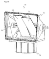
- FIG. 1 shows a three-dimensional view of a Jardinumlenkhaube or device 10 for deflecting and broadening the field of view of a camera.
- the device 10 has, juxtaposed, a first mirror element 12 and a second mirror element 14.
- the two mirror elements 12, 14 are mounted on a shaft 16, which in turn is supported in a housing 18.
- the housing 18 also serves the mechanical stability and as an optical shield.
- a connecting element 20 is provided to connect the device 10 with a camera, so that the lens is aligned with its optical axis to the mirror elements 12, 14.
- the optical axis runs in the perspective of FIG. 1 from bottom to top, wherein the mirror elements 12, 14 provide an image deflection of about 90 °, so that the effective field of view of the camera is above the plane of the paper.
- the mirror elements 12, 14 can be tilted independently of each other in two axes.
- FIG. 1 can be seen a tilt in a longitudinal direction.
- the tilt angle is approximately 45 ° to achieve the desired 90 ° image deflection.
- the tilt angle deviates from exactly 45 °, because both mirror elements 12, 14 are tilted against each other in the longitudinal direction.
- the mirror elements 12, 14 are aligned to partial areas in the object area, which in the perspective of FIG. 1 lie at different heights.
- the two sections complement each other and thus cover a larger width.
- the different tilt angle in the longitudinal direction of the two mirror elements 12, 14 is preferably adjusted as a function of an object distance to the desired width to be detected. A certain overlap of the subregions is possible and even desirable, for example, for joining a common image (stitching).
- the two subregions would still have a lateral mutual offset. Therefore, the mirror elements 12, 14 are also tilted in a transverse direction perpendicular to the longitudinal direction.
- the two mirror elements 12, 14 are inclined to each other and form a wedge.
- the wedge angle is very small and therefore in FIG. 1 barely visible.
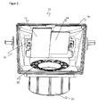
- FIG. 2 shows a three-dimensional view of another embodiment of the device 10.
- the same reference numerals designate the same features.
- this presentation differs from FIG. 1 in that an illumination device 22 is additionally provided, here by way of example in the form of LEDs provided annularly around an opening for the lens of a camera.
- the light of this illumination device 22 is guided by the device 10 in exactly the same way to the viewing area, as is deflected and widened in the reverse light path of the field of view of the camera.
- FIG. 3 shows a schematic sectional view of a camera 24 with a device 10 for field of view broadening.
- the camera 24 has the illumination device 22, a lens or a receiving optical system 26, an image sensor 28 with photosensitive receiving elements arranged in the form of a matrix, and a control and evaluation unit 30.
- the camera 24 is in particular a camera-based code reader whose evaluation unit 30 can identify code areas in recorded image data and read out the code contents.
- the evaluation unit 30 is also preferably able to combine a plurality of recorded subregions or image strips into a common image.
- the camera 24 takes over the mirror elements 12, 14 an object 32 in two sub-areas, wherein the respective light paths are indicated on the two mirror elements 12, 14 by different line widths.
- the offset of the resulting portions on the object 32 may be smaller or larger than shown, this depends on the mutual tilt angle of the mirror elements 12, 14 and the distance the object 32 from.
- the additional tilting of the mirror elements 12, 14 is in FIG. 3 not recognizable due to the sectional view. It causes the two subregions on the object 32 to coincide in the lateral direction, that is to say in FIG FIG. 3 along a perpendicular to the paper plane.
- FIG. 4 The effect of the device 10 on the image of the camera 24 is in FIG. 4 exemplified.
- the object area is shown, where the two subregions 34a-b lie next to one another in the longitudinal direction due to the tilting of the mirror elements 12, 14 and thus cover a greater width.
- the partial regions 34a-b coincide in the transverse direction due to suitable tilting of the mirror elements 34a-b, ie they merge directly into one another.
- the two partial areas 34a-b cover a widened field of vision.
- the subregions 34a-b are imaged one above the other, as on the right in FIG. 4 shown.
- a conventional image sensor 28 or a receiving optical system 26 having a rather square and conventional aspect ratio of, for example, 4/3 or 16/9 can be used and still a very wide image format can be achieved.
- subsequent image processing in the evaluation unit 30 or externally it is readily possible to join the two subregions 34a-b next to one another.
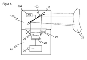
- FIG. 5 shows a sectional view of a camera 24 with a further embodiment of a device 100 for deflecting and broadening the field of view of the camera 24.
- one mirror element 102 is provided, which, however, with the aid of a tilting unit 104 can be tilted. This is indicated by a respective representation of the mirror element 102 with a solid line and a dashed line.
- the mirror element 102 is thus tilted alternately or cyclically between two end positions, wherein the mirror element 102 is substantially in one position as the first mirror element 12 and in the other position as the second mirror element 14 of the embodiments according to Figure 1 to 3 ,
- the two sections 34a-b are then not recorded simultaneously, but alternately and with a time offset.
- the tilt in the transverse direction can be something from that according to FIGS. 1 to 3 deviate to compensate for a feed advance between two shots.
- the field of view is also broadened, but an offset of the subregions 34a-b remains in the lateral direction, ie in the conveying direction.
Landscapes
- Physics & Mathematics (AREA)
- General Physics & Mathematics (AREA)
- Engineering & Computer Science (AREA)
- Electromagnetism (AREA)
- Optics & Photonics (AREA)
- Health & Medical Sciences (AREA)
- General Health & Medical Sciences (AREA)
- Toxicology (AREA)
- Artificial Intelligence (AREA)
- Computer Vision & Pattern Recognition (AREA)
- Theoretical Computer Science (AREA)
- Signal Processing (AREA)
- Multimedia (AREA)
- Studio Devices (AREA)
Claims (9)
- Caméra (24) comprenant un dispositif (10) pour dévier et pour élargir la zone de vision de la caméra (24), ledit dispositif (10) comprenant un premier élément miroir (12) et un second élément miroir (14), qui sont basculés dans une direction longitudinale correspondant à l'axe optique de la caméra (24) et qui sont basculés l'un par rapport à l'autre, afin d'amener à la caméra (24) la lumière provenant d'une zone de vision située latéralement par référence à l'axe optique et pour couvrir avec les deux éléments miroir (12, 14) une largeur de champ de vision requise dans des zones partielles (34a-b) qui se complètent mutuellement,
caractérisée en ce que
le premier élément miroir (12) et le second élément miroir (14) sont agencés l'un à côté de l'autre sur un arbre (16), et en ce que les éléments miroir (12, 14) sont inclinés additionnellement l'un par rapport à l'autre dans une direction transversale perpendiculaire à la direction longitudinale, afin que les zones partielles (34a-b), situées l'une derrière l'autre dans la zone objet, soient couvertes l'une au-dessus de l'autre dans la caméra (24), dans laquelle la caméra (24) comprend un moyen d'éclairage (22), dont la lumière est déviée via les éléments miroir (12, 14) vers la zone de vision, afin d'éclairer la zone de vision. - Caméra (24) selon la revendication 1,
dans laquelle le premier élément miroir (12) et le second élément miroir (14) sont basculés en direction longitudinale de 20° à 70°, en particulier de 40° à 50°, où sensiblement de 45° par rapport à l'axe optique de la caméra (24). - Caméra (24) selon la revendication 1 ou 2,
dans laquelle le premier élément miroir (12) et le second élément miroir (14) sont basculés en direction transversale de la même valeur, mais dans des directions différentes. - Caméra (24) selon l'une des revendications précédentes,
dans laquelle le premier élément miroir (12) et le second élément miroir (14) forment des surfaces de miroir avec la même géométrie. - Caméra (24) selon l'une des revendications précédentes,
dans laquelle le dispositif (10) comprend un troisième élément miroir, qui est basculé en direction longitudinale et en direction transversale par rapport au premier élément miroir (12) et au second élément miroir (14). - Caméra selon l'une des revendications précédentes,
dans laquelle le dispositif (10) comprend un boîtier (18) avec un élément de liaison (20), au moyen duquel le dispositif (10) est relié de façon détachable avec la caméra (24) à titre de capot. - Caméra (24) selon l'une des revendications précédentes,
qui comprend une unité d'évaluation (30), afin de joindre une zone partielle (34a), enregistrée via le premier élément miroir (12), de la zone de vision, et une zone partielle (34b), enregistrée via le second élément miroir (14), de la zone de vision, pour donner une image commune du champ de vision élargi. - Caméra (24) selon l'une des revendications précédentes,
qui est réalisée à titre de lecteur de code basé sur une caméra, avec une unité de décodage (30), pour identifier des zones de code et pour lire des contenus codés. - Procédé pour enregistrer une image provenant d'une zone de vision élargie, avec une caméra (24), dans lequel la lumière provenant d'une zone de vision située latéralement par référence à l'axe optique est amenée à la caméra (24) via deux éléments miroir (12, 14), lesquels sont basculés dans une direction longitudinale correspondant à l'axe optique de la caméra (24) et sont basculés l'un par rapport à l'autre, afin de couvrir avec les deux éléments miroir (12, 14) une largeur de champ de vision requise, dans des zones partielles (34a-b) qui se complètent mutuellement,
caractérisé en ce que
les éléments miroir (12, 14) sont disposés l'un à côté de l'autre sur un arbre (16), et sont inclinés additionnellement l'un par rapport à l'autre dans une direction transversale perpendiculaire à la direction longitudinale, et en ce que dans l'image, les deux zones partielles (34a-b), situées l'une derrière l'autre dans la zone objet, sont enregistrées simultanément via les éléments miroir (12, 14) et disposées l'une au-dessus de l'autre, et en ce que la zone de vision est éclairée par un dispositif d'éclairage (22) de la caméra (24), dont la lumière est déviée via les éléments miroir (12, 14) vers la zone de vision.
Priority Applications (4)
| Application Number | Priority Date | Filing Date | Title |
|---|---|---|---|
| EP13189372.9A EP2863253B1 (fr) | 2013-10-18 | 2013-10-18 | Dispositif de déviation et d'élargissement d'un champ de vision |
| ES13189372.9T ES2550132T3 (es) | 2013-10-18 | 2013-10-18 | Dispositivo para la desviación y para la ampliación del campo de visión |
| DK13189372.9T DK2863253T3 (da) | 2013-10-18 | 2013-10-18 | Device for deviating and for enlarging the field of view |
| US14/505,638 US9141840B2 (en) | 2013-10-18 | 2014-10-03 | Apparatus for deflecting and for widening a visible range |
Applications Claiming Priority (1)
| Application Number | Priority Date | Filing Date | Title |
|---|---|---|---|
| EP13189372.9A EP2863253B1 (fr) | 2013-10-18 | 2013-10-18 | Dispositif de déviation et d'élargissement d'un champ de vision |
Publications (2)
| Publication Number | Publication Date |
|---|---|
| EP2863253A1 EP2863253A1 (fr) | 2015-04-22 |
| EP2863253B1 true EP2863253B1 (fr) | 2015-08-19 |
Family
ID=49385157
Family Applications (1)
| Application Number | Title | Priority Date | Filing Date |
|---|---|---|---|
| EP13189372.9A Active EP2863253B1 (fr) | 2013-10-18 | 2013-10-18 | Dispositif de déviation et d'élargissement d'un champ de vision |
Country Status (4)
| Country | Link |
|---|---|
| US (1) | US9141840B2 (fr) |
| EP (1) | EP2863253B1 (fr) |
| DK (1) | DK2863253T3 (fr) |
| ES (1) | ES2550132T3 (fr) |
Families Citing this family (6)
| Publication number | Priority date | Publication date | Assignee | Title |
|---|---|---|---|---|
| US9027838B2 (en) | 2012-02-06 | 2015-05-12 | Cognex Corporation | System and method for expansion of field of view in a vision system |
| US9892298B2 (en) | 2012-02-06 | 2018-02-13 | Cognex Corporation | System and method for expansion of field of view in a vision system |
| US11966810B2 (en) | 2012-02-06 | 2024-04-23 | Cognex Corporation | System and method for expansion of field of view in a vision system |
| EP3196688A1 (fr) * | 2016-01-22 | 2017-07-26 | Siemens Aktiengesellschaft | Dispositif de detection optique d'objet, capteur optique et embout pour capteur optique |
| JP6724663B2 (ja) | 2016-09-01 | 2020-07-15 | 船井電機株式会社 | スキャナミラー |
| DE202017100478U1 (de) | 2017-01-30 | 2017-03-14 | Sick Ag | Kamera zur Aufnahme von Bilddaten aus einem Erfassungsbereich |
Citations (1)
| Publication number | Priority date | Publication date | Assignee | Title |
|---|---|---|---|---|
| CA1073715A (fr) * | 1977-10-06 | 1980-03-18 | Northern Telecom Limited | Systeme optique pour formation d'images multiples d'un objet lineaire |
Family Cites Families (10)
| Publication number | Priority date | Publication date | Assignee | Title |
|---|---|---|---|---|
| US5870219A (en) * | 1997-01-20 | 1999-02-09 | Geo. Labs, Inc. | Ultra compact scanning system for a wide range of speeds, angles and field depth |
| JPH08171152A (ja) | 1994-12-16 | 1996-07-02 | Olympus Optical Co Ltd | 撮像装置 |
| JP3483963B2 (ja) * | 1994-12-16 | 2004-01-06 | オリンパス株式会社 | ステレオカメラ |
| US5708470A (en) * | 1996-06-10 | 1998-01-13 | Condor Systems, Inc. | Optical monitoring system apparatus |
| JP2004070302A (ja) * | 2002-06-12 | 2004-03-04 | Eriko Shimizu | 立体画面構成方式 |
| CA2659311C (fr) * | 2006-08-18 | 2012-01-10 | Nippon Telegraph And Telephone Corporation | Commutateur optique, procede de commande de commutateur optique et systeme de communication |
| US20090127341A1 (en) * | 2007-11-19 | 2009-05-21 | Xiangyang Feng | Bar-code reading tool |
| US8608076B2 (en) * | 2008-02-12 | 2013-12-17 | Datalogic ADC, Inc. | Monolithic mirror structure for use in a multi-perspective optical code reader |
| US8668150B2 (en) * | 2011-03-17 | 2014-03-11 | United States Postal Service | Systems, methods, and apparatus for overhead scanning of images in a manual distribution environment |
| US9027838B2 (en) | 2012-02-06 | 2015-05-12 | Cognex Corporation | System and method for expansion of field of view in a vision system |
-
2013
- 2013-10-18 EP EP13189372.9A patent/EP2863253B1/fr active Active
- 2013-10-18 DK DK13189372.9T patent/DK2863253T3/da active
- 2013-10-18 ES ES13189372.9T patent/ES2550132T3/es active Active
-
2014
- 2014-10-03 US US14/505,638 patent/US9141840B2/en active Active
Patent Citations (1)
| Publication number | Priority date | Publication date | Assignee | Title |
|---|---|---|---|---|
| CA1073715A (fr) * | 1977-10-06 | 1980-03-18 | Northern Telecom Limited | Systeme optique pour formation d'images multiples d'un objet lineaire |
Also Published As
| Publication number | Publication date |
|---|---|
| DK2863253T3 (da) | 2015-09-14 |
| ES2550132T3 (es) | 2015-11-04 |
| US9141840B2 (en) | 2015-09-22 |
| EP2863253A1 (fr) | 2015-04-22 |
| US20150108218A1 (en) | 2015-04-23 |
Similar Documents
| Publication | Publication Date | Title |
|---|---|---|
| EP2937810B1 (fr) | Système de caméra et procédé de détermination d'un flux mobile d'objets | |
| EP2863253B1 (fr) | Dispositif de déviation et d'élargissement d'un champ de vision | |
| DE202013009198U1 (de) | Vorrichtung zum Umlenken und zur Verbreiterung des Sichtbereichs | |
| EP2693364B1 (fr) | Système de caméra et procédé de détermination d'un flux d'objets | |
| EP3167605B1 (fr) | Dispositif et procédé de détection d'une zone objet | |
| DE102013110615B3 (de) | 3D-Kamera nach dem Stereoskopieprinzip und Verfahren zum Erfassen von Tiefenkarten | |
| EP2693363B1 (fr) | Système de caméra et procédé de détermination d'un flux d'objets | |
| EP2546776A1 (fr) | Lecteur de code basé sur un appareil de prise de vue et son procédé de fabrication ajustée | |
| EP3383026B1 (fr) | Caméra et procédé de détection d'objets se déplaçant vers la caméra dans un dispositif de transport | |
| DE19900498A1 (de) | Verfahren und Einrichtung zur Einsichtnahme des rückwärtigen Beobachtungsraumes bei Kraftfahrzeugen | |
| EP2950519B1 (fr) | Caméra et procédé de capture de données d'image | |
| DE102018123574A1 (de) | Bildgebungvorrichtungen mit zielsystemen | |
| DE112015006637T5 (de) | Bauteilmontagevorrichtung und Verfahren zur Bauteilmontagebestimmung für eine Bauteilmontagevorrichtung | |
| DE102017119282B4 (de) | Optische Abbildungsvorrichtungen und -verfahren | |
| DE102014114506A1 (de) | Kamera zur Montage an einer Fördereinrichtung und Verfahren zur Inspektion oder Identifikation | |
| EP4075394B1 (fr) | Détection d'un flux mobile d'objets | |
| EP3687155B1 (fr) | Dispositif modulaire de caméra et procédé de détection optique | |
| EP2202075A2 (fr) | Procédé et dispositif d'observation d'impression à l'aide d'une caméra à lignes | |
| EP3822198B1 (fr) | Agencement de détection de marchandises de détail | |
| EP3693927B1 (fr) | Alignement d'une caméra à balayage linéaire avec des triangles comme cibles d'alignement. | |
| EP4030234B1 (fr) | Dispositif caméra et procédé de détection d'un objet | |
| DE202014101927U1 (de) | Kamera zur Erfassung eines bewegten Stroms von Objekten | |
| DE202009017346U1 (de) | Optikvorrichtung für einen optoelektronischen Sensor | |
| EP1862309B1 (fr) | Dispositif de détection | |
| DE102014108791B4 (de) | Optoelektronische Vorrichtung und Verfahren zur Überwachung |
Legal Events
| Date | Code | Title | Description |
|---|---|---|---|
| PUAI | Public reference made under article 153(3) epc to a published international application that has entered the european phase |
Free format text: ORIGINAL CODE: 0009012 |
|
| 17P | Request for examination filed |
Effective date: 20140310 |
|
| AK | Designated contracting states |
Kind code of ref document: A1 Designated state(s): AL AT BE BG CH CY CZ DE DK EE ES FI FR GB GR HR HU IE IS IT LI LT LU LV MC MK MT NL NO PL PT RO RS SE SI SK SM TR |
|
| AX | Request for extension of the european patent |
Extension state: BA ME |
|
| GRAP | Despatch of communication of intention to grant a patent |
Free format text: ORIGINAL CODE: EPIDOSNIGR1 |
|
| INTG | Intention to grant announced |
Effective date: 20150520 |
|
| GRAS | Grant fee paid |
Free format text: ORIGINAL CODE: EPIDOSNIGR3 |
|
| GRAA | (expected) grant |
Free format text: ORIGINAL CODE: 0009210 |
|
| AK | Designated contracting states |
Kind code of ref document: B1 Designated state(s): AL AT BE BG CH CY CZ DE DK EE ES FI FR GB GR HR HU IE IS IT LI LT LU LV MC MK MT NL NO PL PT RO RS SE SI SK SM TR |
|
| REG | Reference to a national code |
Ref country code: GB Ref legal event code: FG4D Free format text: NOT ENGLISH |
|
| REG | Reference to a national code |
Ref country code: CH Ref legal event code: EP |
|
| REG | Reference to a national code |
Ref country code: IE Ref legal event code: FG4D Free format text: LANGUAGE OF EP DOCUMENT: GERMAN |
|
| REG | Reference to a national code |
Ref country code: DK Ref legal event code: T3 Effective date: 20150910 |
|
| REG | Reference to a national code |
Ref country code: AT Ref legal event code: REF Ref document number: 744216 Country of ref document: AT Kind code of ref document: T Effective date: 20150915 |
|
| REG | Reference to a national code |
Ref country code: DE Ref legal event code: R096 Ref document number: 502013001041 Country of ref document: DE |
|
| REG | Reference to a national code |
Ref country code: SE Ref legal event code: TRGR |
|
| REG | Reference to a national code |
Ref country code: FR Ref legal event code: PLFP Year of fee payment: 3 |
|
| REG | Reference to a national code |
Ref country code: ES Ref legal event code: FG2A Ref document number: 2550132 Country of ref document: ES Kind code of ref document: T3 Effective date: 20151104 |
|
| REG | Reference to a national code |
Ref country code: NL Ref legal event code: FP |
|
| REG | Reference to a national code |
Ref country code: LT Ref legal event code: MG4D |
|
| PG25 | Lapsed in a contracting state [announced via postgrant information from national office to epo] |
Ref country code: LV Free format text: LAPSE BECAUSE OF FAILURE TO SUBMIT A TRANSLATION OF THE DESCRIPTION OR TO PAY THE FEE WITHIN THE PRESCRIBED TIME-LIMIT Effective date: 20150819 Ref country code: FI Free format text: LAPSE BECAUSE OF FAILURE TO SUBMIT A TRANSLATION OF THE DESCRIPTION OR TO PAY THE FEE WITHIN THE PRESCRIBED TIME-LIMIT Effective date: 20150819 Ref country code: GR Free format text: LAPSE BECAUSE OF FAILURE TO SUBMIT A TRANSLATION OF THE DESCRIPTION OR TO PAY THE FEE WITHIN THE PRESCRIBED TIME-LIMIT Effective date: 20151120 Ref country code: NO Free format text: LAPSE BECAUSE OF FAILURE TO SUBMIT A TRANSLATION OF THE DESCRIPTION OR TO PAY THE FEE WITHIN THE PRESCRIBED TIME-LIMIT Effective date: 20151119 Ref country code: LT Free format text: LAPSE BECAUSE OF FAILURE TO SUBMIT A TRANSLATION OF THE DESCRIPTION OR TO PAY THE FEE WITHIN THE PRESCRIBED TIME-LIMIT Effective date: 20150819 |
|
| PG25 | Lapsed in a contracting state [announced via postgrant information from national office to epo] |
Ref country code: IS Free format text: LAPSE BECAUSE OF FAILURE TO SUBMIT A TRANSLATION OF THE DESCRIPTION OR TO PAY THE FEE WITHIN THE PRESCRIBED TIME-LIMIT Effective date: 20151219 Ref country code: PL Free format text: LAPSE BECAUSE OF FAILURE TO SUBMIT A TRANSLATION OF THE DESCRIPTION OR TO PAY THE FEE WITHIN THE PRESCRIBED TIME-LIMIT Effective date: 20150819 Ref country code: PT Free format text: LAPSE BECAUSE OF FAILURE TO SUBMIT A TRANSLATION OF THE DESCRIPTION OR TO PAY THE FEE WITHIN THE PRESCRIBED TIME-LIMIT Effective date: 20151221 Ref country code: RS Free format text: LAPSE BECAUSE OF FAILURE TO SUBMIT A TRANSLATION OF THE DESCRIPTION OR TO PAY THE FEE WITHIN THE PRESCRIBED TIME-LIMIT Effective date: 20150819 |
|
| PG25 | Lapsed in a contracting state [announced via postgrant information from national office to epo] |
Ref country code: EE Free format text: LAPSE BECAUSE OF FAILURE TO SUBMIT A TRANSLATION OF THE DESCRIPTION OR TO PAY THE FEE WITHIN THE PRESCRIBED TIME-LIMIT Effective date: 20150819 Ref country code: SK Free format text: LAPSE BECAUSE OF FAILURE TO SUBMIT A TRANSLATION OF THE DESCRIPTION OR TO PAY THE FEE WITHIN THE PRESCRIBED TIME-LIMIT Effective date: 20150819 |
|
| REG | Reference to a national code |
Ref country code: DE Ref legal event code: R097 Ref document number: 502013001041 Country of ref document: DE |
|
| PG25 | Lapsed in a contracting state [announced via postgrant information from national office to epo] |
Ref country code: LU Free format text: LAPSE BECAUSE OF FAILURE TO SUBMIT A TRANSLATION OF THE DESCRIPTION OR TO PAY THE FEE WITHIN THE PRESCRIBED TIME-LIMIT Effective date: 20151018 Ref country code: RO Free format text: LAPSE BECAUSE OF FAILURE TO SUBMIT A TRANSLATION OF THE DESCRIPTION OR TO PAY THE FEE WITHIN THE PRESCRIBED TIME-LIMIT Effective date: 20150819 |
|
| PLBE | No opposition filed within time limit |
Free format text: ORIGINAL CODE: 0009261 |
|
| STAA | Information on the status of an ep patent application or granted ep patent |
Free format text: STATUS: NO OPPOSITION FILED WITHIN TIME LIMIT |
|
| PG25 | Lapsed in a contracting state [announced via postgrant information from national office to epo] |
Ref country code: MC Free format text: LAPSE BECAUSE OF FAILURE TO SUBMIT A TRANSLATION OF THE DESCRIPTION OR TO PAY THE FEE WITHIN THE PRESCRIBED TIME-LIMIT Effective date: 20150819 |
|
| 26N | No opposition filed |
Effective date: 20160520 |
|
| REG | Reference to a national code |
Ref country code: IE Ref legal event code: MM4A |
|
| PG25 | Lapsed in a contracting state [announced via postgrant information from national office to epo] |
Ref country code: SI Free format text: LAPSE BECAUSE OF FAILURE TO SUBMIT A TRANSLATION OF THE DESCRIPTION OR TO PAY THE FEE WITHIN THE PRESCRIBED TIME-LIMIT Effective date: 20150819 |
|
| REG | Reference to a national code |
Ref country code: FR Ref legal event code: PLFP Year of fee payment: 4 |
|
| PG25 | Lapsed in a contracting state [announced via postgrant information from national office to epo] |
Ref country code: IE Free format text: LAPSE BECAUSE OF NON-PAYMENT OF DUE FEES Effective date: 20151018 |
|
| PG25 | Lapsed in a contracting state [announced via postgrant information from national office to epo] |
Ref country code: BG Free format text: LAPSE BECAUSE OF FAILURE TO SUBMIT A TRANSLATION OF THE DESCRIPTION OR TO PAY THE FEE WITHIN THE PRESCRIBED TIME-LIMIT Effective date: 20150819 |
|
| PG25 | Lapsed in a contracting state [announced via postgrant information from national office to epo] |
Ref country code: CY Free format text: LAPSE BECAUSE OF FAILURE TO SUBMIT A TRANSLATION OF THE DESCRIPTION OR TO PAY THE FEE WITHIN THE PRESCRIBED TIME-LIMIT Effective date: 20150819 Ref country code: HU Free format text: LAPSE BECAUSE OF FAILURE TO SUBMIT A TRANSLATION OF THE DESCRIPTION OR TO PAY THE FEE WITHIN THE PRESCRIBED TIME-LIMIT; INVALID AB INITIO Effective date: 20131018 |
|
| PG25 | Lapsed in a contracting state [announced via postgrant information from national office to epo] |
Ref country code: BE Free format text: LAPSE BECAUSE OF NON-PAYMENT OF DUE FEES Effective date: 20151031 Ref country code: HR Free format text: LAPSE BECAUSE OF FAILURE TO SUBMIT A TRANSLATION OF THE DESCRIPTION OR TO PAY THE FEE WITHIN THE PRESCRIBED TIME-LIMIT Effective date: 20150819 |
|
| PG25 | Lapsed in a contracting state [announced via postgrant information from national office to epo] |
Ref country code: MT Free format text: LAPSE BECAUSE OF FAILURE TO SUBMIT A TRANSLATION OF THE DESCRIPTION OR TO PAY THE FEE WITHIN THE PRESCRIBED TIME-LIMIT Effective date: 20150819 |
|
| REG | Reference to a national code |
Ref country code: FR Ref legal event code: PLFP Year of fee payment: 5 |
|
| PG25 | Lapsed in a contracting state [announced via postgrant information from national office to epo] |
Ref country code: SM Free format text: LAPSE BECAUSE OF FAILURE TO SUBMIT A TRANSLATION OF THE DESCRIPTION OR TO PAY THE FEE WITHIN THE PRESCRIBED TIME-LIMIT Effective date: 20150819 |
|
| PG25 | Lapsed in a contracting state [announced via postgrant information from national office to epo] |
Ref country code: MK Free format text: LAPSE BECAUSE OF FAILURE TO SUBMIT A TRANSLATION OF THE DESCRIPTION OR TO PAY THE FEE WITHIN THE PRESCRIBED TIME-LIMIT Effective date: 20150819 |
|
| REG | Reference to a national code |
Ref country code: FR Ref legal event code: PLFP Year of fee payment: 6 |
|
| PG25 | Lapsed in a contracting state [announced via postgrant information from national office to epo] |
Ref country code: AL Free format text: LAPSE BECAUSE OF FAILURE TO SUBMIT A TRANSLATION OF THE DESCRIPTION OR TO PAY THE FEE WITHIN THE PRESCRIBED TIME-LIMIT Effective date: 20150819 |
|
| PGFP | Annual fee paid to national office [announced via postgrant information from national office to epo] |
Ref country code: AT Payment date: 20181019 Year of fee payment: 5 |
|
| PGFP | Annual fee paid to national office [announced via postgrant information from national office to epo] |
Ref country code: CH Payment date: 20181217 Year of fee payment: 5 Ref country code: TR Payment date: 20181004 Year of fee payment: 6 |
|
| REG | Reference to a national code |
Ref country code: CH Ref legal event code: PL |
|
| PG25 | Lapsed in a contracting state [announced via postgrant information from national office to epo] |
Ref country code: CZ Free format text: LAPSE BECAUSE OF NON-PAYMENT OF DUE FEES Effective date: 20191018 Ref country code: LI Free format text: LAPSE BECAUSE OF NON-PAYMENT OF DUE FEES Effective date: 20191031 Ref country code: CH Free format text: LAPSE BECAUSE OF NON-PAYMENT OF DUE FEES Effective date: 20191031 |
|
| REG | Reference to a national code |
Ref country code: AT Ref legal event code: MM01 Ref document number: 744216 Country of ref document: AT Kind code of ref document: T Effective date: 20191018 |
|
| PG25 | Lapsed in a contracting state [announced via postgrant information from national office to epo] |
Ref country code: AT Free format text: LAPSE BECAUSE OF NON-PAYMENT OF DUE FEES Effective date: 20191018 |
|
| PG25 | Lapsed in a contracting state [announced via postgrant information from national office to epo] |
Ref country code: ES Free format text: LAPSE BECAUSE OF NON-PAYMENT OF DUE FEES Effective date: 20191019 |
|
| PG25 | Lapsed in a contracting state [announced via postgrant information from national office to epo] |
Ref country code: TR Free format text: LAPSE BECAUSE OF NON-PAYMENT OF DUE FEES Effective date: 20191018 |
|
| PGFP | Annual fee paid to national office [announced via postgrant information from national office to epo] |
Ref country code: NL Payment date: 20231023 Year of fee payment: 11 |
|
| PGFP | Annual fee paid to national office [announced via postgrant information from national office to epo] |
Ref country code: GB Payment date: 20231025 Year of fee payment: 11 |
|
| PGFP | Annual fee paid to national office [announced via postgrant information from national office to epo] |
Ref country code: SE Payment date: 20231025 Year of fee payment: 11 Ref country code: IT Payment date: 20231031 Year of fee payment: 11 Ref country code: FR Payment date: 20231023 Year of fee payment: 11 Ref country code: DK Payment date: 20231025 Year of fee payment: 11 Ref country code: DE Payment date: 20231018 Year of fee payment: 11 |