US11966810B2 - System and method for expansion of field of view in a vision system - Google Patents
System and method for expansion of field of view in a vision system Download PDFInfo
- Publication number
- US11966810B2 US11966810B2 US16/669,603 US201916669603A US11966810B2 US 11966810 B2 US11966810 B2 US 11966810B2 US 201916669603 A US201916669603 A US 201916669603A US 11966810 B2 US11966810 B2 US 11966810B2
- Authority
- US
- United States
- Prior art keywords
- mirror
- assembly
- mirrors
- camera
- image
- Prior art date
- Legal status (The legal status is an assumption and is not a legal conclusion. Google has not performed a legal analysis and makes no representation as to the accuracy of the status listed.)
- Active, expires
Links
- 230000004438 eyesight Effects 0.000 title claims abstract description 96
- 238000000034 method Methods 0.000 title claims description 95
- 230000003287 optical effect Effects 0.000 claims abstract description 173
- 230000008569 process Effects 0.000 claims description 53
- 230000006870 function Effects 0.000 claims description 14
- 238000005286 illumination Methods 0.000 claims description 11
- 238000004891 communication Methods 0.000 claims description 8
- 230000005540 biological transmission Effects 0.000 claims description 3
- 238000001914 filtration Methods 0.000 claims description 3
- 230000010287 polarization Effects 0.000 claims description 3
- 238000010586 diagram Methods 0.000 description 21
- 230000000712 assembly Effects 0.000 description 20
- 238000000429 assembly Methods 0.000 description 20
- 230000008878 coupling Effects 0.000 description 16
- 238000010168 coupling process Methods 0.000 description 16
- 238000005859 coupling reaction Methods 0.000 description 16
- 238000012545 processing Methods 0.000 description 15
- 238000003384 imaging method Methods 0.000 description 14
- 230000033001 locomotion Effects 0.000 description 14
- 238000007689 inspection Methods 0.000 description 12
- 238000010276 construction Methods 0.000 description 11
- 239000000463 material Substances 0.000 description 10
- 229910052751 metal Inorganic materials 0.000 description 10
- 239000002184 metal Substances 0.000 description 10
- 230000000694 effects Effects 0.000 description 9
- 239000007788 liquid Substances 0.000 description 9
- 238000005259 measurement Methods 0.000 description 9
- 229920000642 polymer Polymers 0.000 description 7
- 230000026676 system process Effects 0.000 description 7
- 238000006243 chemical reaction Methods 0.000 description 6
- 230000037361 pathway Effects 0.000 description 6
- 239000004417 polycarbonate Substances 0.000 description 6
- 229910000838 Al alloy Inorganic materials 0.000 description 5
- 239000002131 composite material Substances 0.000 description 5
- 238000001125 extrusion Methods 0.000 description 5
- 239000011521 glass Substances 0.000 description 5
- 230000001154 acute effect Effects 0.000 description 4
- 238000013459 approach Methods 0.000 description 4
- 238000004519 manufacturing process Methods 0.000 description 4
- 230000007935 neutral effect Effects 0.000 description 4
- 230000001960 triggered effect Effects 0.000 description 4
- XYDVHKCVOMGRSY-UHFFFAOYSA-N 4-(4-benzylphenyl)-1,3-thiazol-2-amine Chemical compound S1C(N)=NC(C=2C=CC(CC=3C=CC=CC=3)=CC=2)=C1 XYDVHKCVOMGRSY-UHFFFAOYSA-N 0.000 description 3
- 101000928034 Homo sapiens Proteasomal ubiquitin receptor ADRM1 Proteins 0.000 description 3
- 102100036915 Proteasomal ubiquitin receptor ADRM1 Human genes 0.000 description 3
- 229910052782 aluminium Inorganic materials 0.000 description 3
- XAGFODPZIPBFFR-UHFFFAOYSA-N aluminium Chemical compound [Al] XAGFODPZIPBFFR-UHFFFAOYSA-N 0.000 description 3
- 230000007423 decrease Effects 0.000 description 3
- 238000013461 design Methods 0.000 description 3
- 230000007613 environmental effect Effects 0.000 description 3
- 230000007246 mechanism Effects 0.000 description 3
- 238000012986 modification Methods 0.000 description 3
- 230000004048 modification Effects 0.000 description 3
- 238000000465 moulding Methods 0.000 description 3
- 229920000515 polycarbonate Polymers 0.000 description 3
- 238000012546 transfer Methods 0.000 description 3
- 101100434014 Saccharomyces cerevisiae (strain ATCC 204508 / S288c) ACM1 gene Proteins 0.000 description 2
- 229910000831 Steel Inorganic materials 0.000 description 2
- 239000000853 adhesive Substances 0.000 description 2
- 230000001070 adhesive effect Effects 0.000 description 2
- 239000011324 bead Substances 0.000 description 2
- 238000005452 bending Methods 0.000 description 2
- 230000009286 beneficial effect Effects 0.000 description 2
- 230000008901 benefit Effects 0.000 description 2
- 230000003247 decreasing effect Effects 0.000 description 2
- 239000000428 dust Substances 0.000 description 2
- -1 etc.) Polymers 0.000 description 2
- 239000012530 fluid Substances 0.000 description 2
- 230000004313 glare Effects 0.000 description 2
- 238000013507 mapping Methods 0.000 description 2
- 230000005855 radiation Effects 0.000 description 2
- 230000004044 response Effects 0.000 description 2
- 125000006850 spacer group Chemical group 0.000 description 2
- 239000010959 steel Substances 0.000 description 2
- YLJREFDVOIBQDA-UHFFFAOYSA-N tacrine Chemical compound C1=CC=C2C(N)=C(CCCC3)C3=NC2=C1 YLJREFDVOIBQDA-UHFFFAOYSA-N 0.000 description 2
- 229960001685 tacrine Drugs 0.000 description 2
- 101100161469 Arabidopsis thaliana ABCB23 gene Proteins 0.000 description 1
- 101100161471 Arabidopsis thaliana ABCB24 gene Proteins 0.000 description 1
- 101100132433 Arabidopsis thaliana VIII-1 gene Proteins 0.000 description 1
- 101100459319 Arabidopsis thaliana VIII-2 gene Proteins 0.000 description 1
- 229920004943 Delrin® Polymers 0.000 description 1
- 239000004593 Epoxy Substances 0.000 description 1
- 244000043261 Hevea brasiliensis Species 0.000 description 1
- FYYHWMGAXLPEAU-UHFFFAOYSA-N Magnesium Chemical compound [Mg] FYYHWMGAXLPEAU-UHFFFAOYSA-N 0.000 description 1
- 101100324822 Neurospora crassa (strain ATCC 24698 / 74-OR23-1A / CBS 708.71 / DSM 1257 / FGSC 987) fes-4 gene Proteins 0.000 description 1
- 239000004677 Nylon Substances 0.000 description 1
- 101100383103 Saccharomyces cerevisiae (strain ATCC 204508 / S288c) CDC7 gene Proteins 0.000 description 1
- 101100188423 Saccharomyces cerevisiae (strain ATCC 204508 / S288c) OAF1 gene Proteins 0.000 description 1
- 101100350434 Saccharomyces cerevisiae (strain ATCC 204508 / S288c) ORC3 gene Proteins 0.000 description 1
- 101100297701 Saccharomyces cerevisiae (strain ATCC 204508 / S288c) PIP2 gene Proteins 0.000 description 1
- 239000004809 Teflon Substances 0.000 description 1
- 229920006362 Teflon® Polymers 0.000 description 1
- NIXOWILDQLNWCW-UHFFFAOYSA-N acrylic acid group Chemical group C(C=C)(=O)O NIXOWILDQLNWCW-UHFFFAOYSA-N 0.000 description 1
- 230000009471 action Effects 0.000 description 1
- 239000008186 active pharmaceutical agent Substances 0.000 description 1
- 238000007792 addition Methods 0.000 description 1
- 101150115605 atm1 gene Proteins 0.000 description 1
- 238000007630 basic procedure Methods 0.000 description 1
- 238000005266 casting Methods 0.000 description 1
- 230000009956 central mechanism Effects 0.000 description 1
- 239000003795 chemical substances by application Substances 0.000 description 1
- 238000000576 coating method Methods 0.000 description 1
- 239000003086 colorant Substances 0.000 description 1
- 150000001875 compounds Chemical class 0.000 description 1
- 239000000356 contaminant Substances 0.000 description 1
- 238000011109 contamination Methods 0.000 description 1
- 230000001419 dependent effect Effects 0.000 description 1
- 238000004512 die casting Methods 0.000 description 1
- 238000006073 displacement reaction Methods 0.000 description 1
- 239000002783 friction material Substances 0.000 description 1
- 230000005484 gravity Effects 0.000 description 1
- 230000017525 heat dissipation Effects 0.000 description 1
- 238000001746 injection moulding Methods 0.000 description 1
- 230000010354 integration Effects 0.000 description 1
- 230000001788 irregular Effects 0.000 description 1
- 238000003698 laser cutting Methods 0.000 description 1
- 238000003754 machining Methods 0.000 description 1
- 239000011777 magnesium Substances 0.000 description 1
- 229910052749 magnesium Inorganic materials 0.000 description 1
- 239000012528 membrane Substances 0.000 description 1
- 150000002739 metals Chemical class 0.000 description 1
- 238000012544 monitoring process Methods 0.000 description 1
- 229920003052 natural elastomer Polymers 0.000 description 1
- 229920001194 natural rubber Polymers 0.000 description 1
- 229920001778 nylon Polymers 0.000 description 1
- 230000001151 other effect Effects 0.000 description 1
- 230000000149 penetrating effect Effects 0.000 description 1
- 239000002985 plastic film Substances 0.000 description 1
- 229920005597 polymer membrane Polymers 0.000 description 1
- 238000004080 punching Methods 0.000 description 1
- 230000009467 reduction Effects 0.000 description 1
- 238000005070 sampling Methods 0.000 description 1
- 238000000926 separation method Methods 0.000 description 1
- 238000004513 sizing Methods 0.000 description 1
- 239000007787 solid Substances 0.000 description 1
- 239000000243 solution Substances 0.000 description 1
- 238000006467 substitution reaction Methods 0.000 description 1
- 230000001360 synchronised effect Effects 0.000 description 1
- 229920001169 thermoplastic Polymers 0.000 description 1
- 239000004416 thermosoftening plastic Substances 0.000 description 1
Images


Classifications
-
- G—PHYSICS
- G06—COMPUTING; CALCULATING OR COUNTING
- G06K—GRAPHICAL DATA READING; PRESENTATION OF DATA; RECORD CARRIERS; HANDLING RECORD CARRIERS
- G06K7/00—Methods or arrangements for sensing record carriers, e.g. for reading patterns
- G06K7/10—Methods or arrangements for sensing record carriers, e.g. for reading patterns by electromagnetic radiation, e.g. optical sensing; by corpuscular radiation
- G06K7/10544—Methods or arrangements for sensing record carriers, e.g. for reading patterns by electromagnetic radiation, e.g. optical sensing; by corpuscular radiation by scanning of the records by radiation in the optical part of the electromagnetic spectrum
- G06K7/10712—Fixed beam scanning
- G06K7/10722—Photodetector array or CCD scanning
- G06K7/10732—Light sources
-
- G—PHYSICS
- G02—OPTICS
- G02B—OPTICAL ELEMENTS, SYSTEMS OR APPARATUS
- G02B17/00—Systems with reflecting surfaces, with or without refracting elements
- G02B17/02—Catoptric systems, e.g. image erecting and reversing system
- G02B17/023—Catoptric systems, e.g. image erecting and reversing system for extending or folding an optical path, e.g. delay lines
-
- G—PHYSICS
- G02—OPTICS
- G02B—OPTICAL ELEMENTS, SYSTEMS OR APPARATUS
- G02B17/00—Systems with reflecting surfaces, with or without refracting elements
- G02B17/02—Catoptric systems, e.g. image erecting and reversing system
- G02B17/06—Catoptric systems, e.g. image erecting and reversing system using mirrors only, i.e. having only one curved mirror
-
- G—PHYSICS
- G02—OPTICS
- G02B—OPTICAL ELEMENTS, SYSTEMS OR APPARATUS
- G02B26/00—Optical devices or arrangements for the control of light using movable or deformable optical elements
- G02B26/08—Optical devices or arrangements for the control of light using movable or deformable optical elements for controlling the direction of light
- G02B26/10—Scanning systems
- G02B26/105—Scanning systems with one or more pivoting mirrors or galvano-mirrors
-
- G—PHYSICS
- G02—OPTICS
- G02B—OPTICAL ELEMENTS, SYSTEMS OR APPARATUS
- G02B26/00—Optical devices or arrangements for the control of light using movable or deformable optical elements
- G02B26/08—Optical devices or arrangements for the control of light using movable or deformable optical elements for controlling the direction of light
- G02B26/10—Scanning systems
- G02B26/12—Scanning systems using multifaceted mirrors
-
- G—PHYSICS
- G02—OPTICS
- G02B—OPTICAL ELEMENTS, SYSTEMS OR APPARATUS
- G02B27/00—Optical systems or apparatus not provided for by any of the groups G02B1/00 - G02B26/00, G02B30/00
- G02B27/10—Beam splitting or combining systems
- G02B27/1066—Beam splitting or combining systems for enhancing image performance, like resolution, pixel numbers, dual magnifications or dynamic range, by tiling, slicing or overlapping fields of view
-
- G—PHYSICS
- G02—OPTICS
- G02B—OPTICAL ELEMENTS, SYSTEMS OR APPARATUS
- G02B27/00—Optical systems or apparatus not provided for by any of the groups G02B1/00 - G02B26/00, G02B30/00
- G02B27/10—Beam splitting or combining systems
- G02B27/14—Beam splitting or combining systems operating by reflection only
- G02B27/143—Beam splitting or combining systems operating by reflection only using macroscopically faceted or segmented reflective surfaces
-
- G—PHYSICS
- G03—PHOTOGRAPHY; CINEMATOGRAPHY; ANALOGOUS TECHNIQUES USING WAVES OTHER THAN OPTICAL WAVES; ELECTROGRAPHY; HOLOGRAPHY
- G03B—APPARATUS OR ARRANGEMENTS FOR TAKING PHOTOGRAPHS OR FOR PROJECTING OR VIEWING THEM; APPARATUS OR ARRANGEMENTS EMPLOYING ANALOGOUS TECHNIQUES USING WAVES OTHER THAN OPTICAL WAVES; ACCESSORIES THEREFOR
- G03B17/00—Details of cameras or camera bodies; Accessories therefor
- G03B17/02—Bodies
- G03B17/17—Bodies with reflectors arranged in beam forming the photographic image, e.g. for reducing dimensions of camera
-
- G—PHYSICS
- G03—PHOTOGRAPHY; CINEMATOGRAPHY; ANALOGOUS TECHNIQUES USING WAVES OTHER THAN OPTICAL WAVES; ELECTROGRAPHY; HOLOGRAPHY
- G03B—APPARATUS OR ARRANGEMENTS FOR TAKING PHOTOGRAPHS OR FOR PROJECTING OR VIEWING THEM; APPARATUS OR ARRANGEMENTS EMPLOYING ANALOGOUS TECHNIQUES USING WAVES OTHER THAN OPTICAL WAVES; ACCESSORIES THEREFOR
- G03B37/00—Panoramic or wide-screen photography; Photographing extended surfaces, e.g. for surveying; Photographing internal surfaces, e.g. of pipe
-
- G—PHYSICS
- G06—COMPUTING; CALCULATING OR COUNTING
- G06K—GRAPHICAL DATA READING; PRESENTATION OF DATA; RECORD CARRIERS; HANDLING RECORD CARRIERS
- G06K7/00—Methods or arrangements for sensing record carriers, e.g. for reading patterns
- G06K7/10—Methods or arrangements for sensing record carriers, e.g. for reading patterns by electromagnetic radiation, e.g. optical sensing; by corpuscular radiation
- G06K7/10544—Methods or arrangements for sensing record carriers, e.g. for reading patterns by electromagnetic radiation, e.g. optical sensing; by corpuscular radiation by scanning of the records by radiation in the optical part of the electromagnetic spectrum
- G06K7/10554—Moving beam scanning
- G06K7/10594—Beam path
- G06K7/10603—Basic scanning using moving elements
-
- G—PHYSICS
- G06—COMPUTING; CALCULATING OR COUNTING
- G06K—GRAPHICAL DATA READING; PRESENTATION OF DATA; RECORD CARRIERS; HANDLING RECORD CARRIERS
- G06K7/00—Methods or arrangements for sensing record carriers, e.g. for reading patterns
- G06K7/10—Methods or arrangements for sensing record carriers, e.g. for reading patterns by electromagnetic radiation, e.g. optical sensing; by corpuscular radiation
- G06K7/10544—Methods or arrangements for sensing record carriers, e.g. for reading patterns by electromagnetic radiation, e.g. optical sensing; by corpuscular radiation by scanning of the records by radiation in the optical part of the electromagnetic spectrum
- G06K7/10712—Fixed beam scanning
- G06K7/10722—Photodetector array or CCD scanning
-
- G—PHYSICS
- G06—COMPUTING; CALCULATING OR COUNTING
- G06K—GRAPHICAL DATA READING; PRESENTATION OF DATA; RECORD CARRIERS; HANDLING RECORD CARRIERS
- G06K7/00—Methods or arrangements for sensing record carriers, e.g. for reading patterns
- G06K7/10—Methods or arrangements for sensing record carriers, e.g. for reading patterns by electromagnetic radiation, e.g. optical sensing; by corpuscular radiation
- G06K7/10544—Methods or arrangements for sensing record carriers, e.g. for reading patterns by electromagnetic radiation, e.g. optical sensing; by corpuscular radiation by scanning of the records by radiation in the optical part of the electromagnetic spectrum
- G06K7/10821—Methods or arrangements for sensing record carriers, e.g. for reading patterns by electromagnetic radiation, e.g. optical sensing; by corpuscular radiation by scanning of the records by radiation in the optical part of the electromagnetic spectrum further details of bar or optical code scanning devices
- G06K7/10831—Arrangement of optical elements, e.g. lenses, mirrors, prisms
-
- G—PHYSICS
- G06—COMPUTING; CALCULATING OR COUNTING
- G06V—IMAGE OR VIDEO RECOGNITION OR UNDERSTANDING
- G06V10/00—Arrangements for image or video recognition or understanding
- G06V10/10—Image acquisition
- G06V10/12—Details of acquisition arrangements; Constructional details thereof
- G06V10/14—Optical characteristics of the device performing the acquisition or on the illumination arrangements
- G06V10/141—Control of illumination
-
- G—PHYSICS
- G06—COMPUTING; CALCULATING OR COUNTING
- G06V—IMAGE OR VIDEO RECOGNITION OR UNDERSTANDING
- G06V10/00—Arrangements for image or video recognition or understanding
- G06V10/10—Image acquisition
- G06V10/12—Details of acquisition arrangements; Constructional details thereof
- G06V10/14—Optical characteristics of the device performing the acquisition or on the illumination arrangements
- G06V10/147—Details of sensors, e.g. sensor lenses
-
- G—PHYSICS
- G06—COMPUTING; CALCULATING OR COUNTING
- G06V—IMAGE OR VIDEO RECOGNITION OR UNDERSTANDING
- G06V30/00—Character recognition; Recognising digital ink; Document-oriented image-based pattern recognition
- G06V30/10—Character recognition
- G06V30/22—Character recognition characterised by the type of writing
- G06V30/224—Character recognition characterised by the type of writing of printed characters having additional code marks or containing code marks
- G06V30/2247—Characters composed of bars, e.g. CMC-7
-
- H—ELECTRICITY
- H04—ELECTRIC COMMUNICATION TECHNIQUE
- H04N—PICTORIAL COMMUNICATION, e.g. TELEVISION
- H04N23/00—Cameras or camera modules comprising electronic image sensors; Control thereof
-
- H—ELECTRICITY
- H04—ELECTRIC COMMUNICATION TECHNIQUE
- H04N—PICTORIAL COMMUNICATION, e.g. TELEVISION
- H04N23/00—Cameras or camera modules comprising electronic image sensors; Control thereof
- H04N23/50—Constructional details
- H04N23/55—Optical parts specially adapted for electronic image sensors; Mounting thereof
-
- H—ELECTRICITY
- H04—ELECTRIC COMMUNICATION TECHNIQUE
- H04N—PICTORIAL COMMUNICATION, e.g. TELEVISION
- H04N23/00—Cameras or camera modules comprising electronic image sensors; Control thereof
- H04N23/60—Control of cameras or camera modules
- H04N23/698—Control of cameras or camera modules for achieving an enlarged field of view, e.g. panoramic image capture
-
- G—PHYSICS
- G03—PHOTOGRAPHY; CINEMATOGRAPHY; ANALOGOUS TECHNIQUES USING WAVES OTHER THAN OPTICAL WAVES; ELECTROGRAPHY; HOLOGRAPHY
- G03B—APPARATUS OR ARRANGEMENTS FOR TAKING PHOTOGRAPHS OR FOR PROJECTING OR VIEWING THEM; APPARATUS OR ARRANGEMENTS EMPLOYING ANALOGOUS TECHNIQUES USING WAVES OTHER THAN OPTICAL WAVES; ACCESSORIES THEREFOR
- G03B17/00—Details of cameras or camera bodies; Accessories therefor
- G03B17/56—Accessories
- G03B17/565—Optical accessories, e.g. converters for close-up photography, tele-convertors, wide-angle convertors
-
- H—ELECTRICITY
- H04—ELECTRIC COMMUNICATION TECHNIQUE
- H04N—PICTORIAL COMMUNICATION, e.g. TELEVISION
- H04N23/00—Cameras or camera modules comprising electronic image sensors; Control thereof
- H04N23/45—Cameras or camera modules comprising electronic image sensors; Control thereof for generating image signals from two or more image sensors being of different type or operating in different modes, e.g. with a CMOS sensor for moving images in combination with a charge-coupled device [CCD] for still images
Definitions
- This invention relates to vision systems, and more particularly to systems and methods for expanding the field of view of a vision system camera lens.
- Vision systems that perform measurement, inspection, alignment of objects and/or decoding of symbology (e.g. bar codes—also termed “IDs”) are used in a wide range of applications and industries. These systems are based around the use of an image sensor, which acquires images (typically grayscale or color, and in one, two or three dimensions) of the subject or object, and processes these acquired images using an on-board or interconnected vision system processor.
- the processor generally includes both processing hardware and non-transitory computer-readable program instructions that perform one or more vision system processes to generate a desired output based upon the image's processed information. This image information is typically provided within an array of image pixels each having various colors and/or intensities.
- an ID reader also termed herein, a “camera”
- the user or automated process acquires an image of an object that is believed to contain one or more barcodes.
- the image is processed to identify barcode features, which are then decoded by a decoding process and/or processor obtain the inherent alphanumeric data represented by the code.
- a common use for ID readers is to track and sort objects moving along a line (e.g. a conveyor) in manufacturing and logistics operations.
- the ID reader can be positioned over the line at an appropriate viewing angle to acquire any expected IDs on respective objects as they each move through the field of view.
- the focal distance of the reader with respect to the object can vary, depending on the placement of the reader with respect to the line and the size of the object. That is, a larger object may cause IDs thereon to be located closer to the reader, while a smaller/flatter object may contain IDs that are further from the reader. In each case, the ID should appear with sufficient resolution to be properly imaged and decoded.
- the field of view of a single reader particularly in with widthwise direction (perpendicular to line motion) is often limited.
- the lens and sensor of a single ID reader may not have sufficient field of view in the widthwise direction to cover the entire width of the line while maintaining needed resolution for accurate imaging and decoding of IDs. Failure to image the full width can cause the reader to miss IDs that are outside of the field of view.
- CMOS sensors e.g. CMOS sensors, but other types, such as CCD, are also contemplated
- CMOS sensors are commercially available in a standard format, such as 4 ⁇ 3 or 16 ⁇ 9, and thus, providing a larger widthwise resolution also entails a similarly enlarged height (i.e. the direction of line motion) resolution.
- the increased height direction may cause the sensor to capture the same ID in a plurality of captured image frames as the object passes through the enlarged field of view. This, in turn leads to extraneous processing and/or decoding of the same ID and the risk that a single object is mistaken for a plurality of objects passing under the reader.
- FOV field of view
- Such FOV expanders have been found to better utilize the (often) standard 4:3 aspect ratio with respect to the imaged scene, and also to advantageously lengthen the optical path for better depth of field. Hence, designs that further leverage these and other advantages of FOV expanders are highly desirable.
- This invention overcomes disadvantages of the prior art by providing a system and method for expanding the field of view of a scene imaged by a vision system camera assembly having an image sensor defining an image plane.
- the system and method desirably expands the field of view (FOV) of an ID reader or other vision system arrangement in the widthwise direction with respect to a moving line in a manner that does not decrease needed resolution.
- the system and method also allows use of a conventional sensor and camera optics and is generally straightforward to install and use.
- the system and method desirably increases resolution in the height/line-motion direction.
- the system and method can be adapted for use in space-constrained applications, such as those arrangements where a downwardly mounted camera or a long focal distance in the vertical direction is not available.
- the system including the FOVE, can be employed as an ID reader in (for example) logistics operations, such that the field of view is generally free of loss of normal resolution of a camera assembly sensor, and ensures that features of interest, such as IDs, are fully imaged across the entire expanded field.
- a field of view expander comprises a removable accessory, provided to a camera assembly, with mirrors directed to receive light from different widthwise portions of a scene, which can be a moving line of objects.
- the system and method herein employs housings, optics and mirrors that allow a plurality of image sensors and associated camera optics to extend/lengthen the optical path.
- These arrangements effectively reduce the distance between such multiple image sensors via redirection of the optical paths of associated, partial FOVs using e.g. mirrors. This makes it possible to position the two (or more) image sensors closer to each other in an FOV separator assembly. Closer placement of image sensors advantageously allows for an improved electronic arrangement, with easier transfer of high speed image and data signals, less interference from EM radiation, etc.
- the arrangement enables the FOV separator to define and overall more-compact arrangement.
- the exemplary embodiments herein reduce the overall dimensions of the system by folding the optical path.
- the exemplary embodiments also advantageously allow for flexible pixel mapping. In general, varying the distance and angle of the mirrors is an easy way to optimize the system for applications with different requirements on resolution and size of the FOV and associated overlap area between the adjacent FOVs relative to each image sensor/optics.
- system for separating a field of view (FOV) of a scene imaged by a vision system camera assembly in which the system is constructed and arranged to search and analyze features of interest in the scene is provided.
- a separating mirror assembly is constructed and arranged to redirect a first optical path of at least a first optics with respect to at least a first image sensor in the camera assembly.
- At least a first reflecting assembly redirects the first optical path from the separating mirror toward a first FOV, the first optical path is extended free of splitting the image projected from the scene on the image sensor.
- the separating mirror assembly is constructed and arranged to redirect a second optical path of at least a second optics with respect to a second image sensor in the camera assembly.
- At least a second reflecting assembly redirects the second optical path from the separating mirror toward a second FOV.
- the second optical path is extended free of splitting the image projected from the scene on the second image sensor.
- the first reflecting assembly comprises at least one mirror located at a first predetermined spacing from the separating mirror along the first optical path and the second reflecting assembly comprises at least one mirror located at a second predetermined spacing along the second optical path.
- the first reflecting assembly comprises at least two mirrors. At least one of the first reflecting assembly and the second reflecting assembly, respectively, can redirect the first optical path and the second optical path through 90 degrees.
- the two mirrors of at least one of the first reflecting assembly and the second reflecting assembly can be located both above and below an image plane of at least one of the first image sensor and the second image sensor, respectively.
- the at least two mirrors of at least one of the first reflecting assembly and the second reflecting assembly can be arranged to convert roll in the camera assembly into tilt in the first FOV and the second FOV, respectively.
- the separating mirror is located in a core module attached to the camera assembly and the first reflecting assembly is located at least partially in a first mirror module and a second mirror module in optical communication through one or more passages in the core module with the separating mirror, the core module. The first mirror module and the second mirror module are thereby attached to a base mounting.
- the separating mirror is located in a core module attached to the camera assembly, and the first reflecting assembly and second reflecting assembly are located at least partially in first mirror module and the second mirror module, respectively, both attached to the core module and in optical communication through passages in the core module.
- the core module can comprise a plurality of receptacles for supporting and electrically connecting electronic modules, which perform at least one of a plurality of illumination and sensing functions.
- the receptacles can comprise electrical connections that interconnect with control circuitry on the camera assembly.
- the first mirror module and the second mirror module can define differing optical characteristics, including at least one of differing viewing directions, differing FOV sizes, differing optical path lengths, differing transmission and/or reflection characteristics, differing optical filtering characteristics, differing wavelength characteristics and differing polarization characteristics.
- the core comprises at least four optical passages for attaching at least four components in each of four rectilinear directions.
- the searched feature of interest can be an ID code, the system further comprising an ID code decoding system that receives information related to located ID codes from the vision system camera assembly and outputs code data to a further interconnected process.
- the ID code can be located on an object moving on a conveyor through the scene.
- a system for expanding a field of view of a scene imaged by a vision system camera assembly along four discrete optical paths with four partial fields of view (FOVs) of a scene is provided. At least two mirrors redirect and fold the optical path relative to the camera assembly so as to define the at least four partial FOVs along four respective optical paths. Each of the partial FOVs is captured by the camera assembly. The four partial FOVs are arranged to image at least a portion of a top and surrounding sides of a box-like object at the scene.
- the camera assembly comprises at least two image sensors, in which each of the two image sensors captures the partial FOVs along two discrete optical paths, respectively.
- the (at least) two mirrors can be located on an internal platform of a sealed shell in optical communication with the camera assembly.
- At least four reflecting assemblies can be provided, respectively, along each of the four optical paths, in which the reflecting assemblies can be located external to the sealed shell.
- the separating mirror assembly is constructed and arranged to rotate a selected amount around an intersection line between mirror planes with respect to mirrors of the separating mirror assembly, to adjust the alignment between the first FOV and the second FOV relative to an optical axis of the camera assembly.
- a system for expanding a field of view (FOV) of a scene imaged by a vision system camera is provided.
- the system is constructed and arranged to capture at least two partial fields of views (FOVs) of a scene along two respective optical paths.
- the partial FOVs are partially overlapping in their widthwise direction.
- At least two respective optical paths can each comprise a discrete lens and image sensor.
- the respective optical axes of the partial FOVs can be approximately parallel.
- a distance between the respective optical axes of the partial FOVs, which are adjacent to each image sensor can be smaller than a distance between the optical axes that are adjacent to the scene.
- the (at least) two mirrors can be located closest to each image sensor along each of the (at least) two respective optical paths and can be mounted together in a first assembly.
- Each of the (at least) two mirrors define planes that intersect along an intersection line and further comprising a rotation assembly that concurrently rotates the (at least) two mirrors by a selected amount around the intersection line to adjust the alignment between the partial FOVs relative to an optical axis of the camera assembly.
- a virtual rotation axis is defined at an intersection of the respective planes of each of the at least two mirrors by at least two flexures located at a distance from the virtual rotation axis.
- FIG. 1 is a perspective view of a vision system including a field of view expander (FOVE) according to an illustrative embodiment acquiring an image of an exemplary object on a moving line;
- FOVE field of view expander
- FIG. 1 A is a side cross section of the vision system and FOVE of FIG. 1 ;
- FIG. 2 is a more detailed perspective view of a mirror arrangement in the illustrative vision system and FOVE of FIG. 1 with housing and support components omitted to depict the relative placement of mirrors therein;
- FIG. 3 is a top view of a mirror arrangement in the illustrative vision system and FOVE of FIG. 1 with housing and support components omitted;
- FIG. 4 is a top view of a mirror arrangement in the illustrative vision system and FOVE of FIG. 1 with housing and support components omitted showing the relative angles of received light transmitted from an object, through the FOVE, to the camera;
- FIG. 4 A is a front view of the mirror arrangement of the FOVE of FIG. 1
- FIG. 5 is a depiction of an acquired image of an exemplary object including a pair of exemplary IDs each respectively located within each discrete field of view portion of the illustrative vision system and FOVE of FIG. 1 ;
- FIG. 6 is a diagram of an acquired image of an exemplary object including a discrete exemplary ID located within an overlap region within each discrete field of view portion of the illustrative vision system and FOVE of FIG. 1 ;
- FIG. 7 is a diagram of an exemplary sensor divided between an upper strip that images the right field of view and a lower strip that images the left field of view based upon the division of the field of view provided by the illustrative FOVE of FIG. 1 ;
- FIG. 8 is a flow diagram of a process for acquiring and decoding IDs using a vision system/ID reader including the illustrative FOVE of FIG. 1 ;
- FIG. 9 is a top view of an interconnected arrangement of a plurality of ID readers to image a wide field of view each employing an illustrative FOVE according to an illustrative embodiment
- FIG. 10 is a perspective view of a vision system/ID reader including a FOVE according to an alternate embodiment in which four discrete strips relative to the image sensor;
- FIG. 11 is a schematic diagram of a rotating, polygonal mirror used to acquire a plurality of image frames across an expanded field of view;
- FIG. 12 is a front perspective view of a vision system including an FOVE according to a further illustrative embodiment, having optics arranged generally according to the embodiment of FIG. 1 , and including an optional removably mounted illumination assembly;
- FIG. 13 is a rear perspective view of the vision system and FOVE of FIG. 12 ;
- FIG. 14 is a rear perspective view of a vision system with an FOVE having a metal casing with built in bracket channels according to a further illustrative embodiment and further defining overlap regions between FOVE fields of views;
- FIG. 14 A is a diagram of the positions of overlapping and non-overlapping regions on partial images projected onto the imager by the FOVE of FIG. 14 ;
- FIG. 15 is a perspective view of the arrangement of mirrors and associated optical path for the FOVE of FIG. 14 ;
- FIG. 16 is a bottom perspective view of the vision system and FOVE of FIG. 14 ;
- FIG. 17 is a side cross section of the vision system and FOVE taken along line 17 - 17 of FIG. 16 ;
- FIG. 17 A is a schematic diagram of a liquid lens assembly for use with the vision system and FOVE according to various embodiments herein;
- FIG. 18 is a more detailed top cross section of the bracket and movable lens shroud in the coupling region between the camera assembly and FOVE body in the vision system and FOVE of FIG. 14 ;
- FIG. 19 is an exploded perspective view of the vision system and FOVE of FIG. 14 ;
- FIG. 20 is an exploded fragmentary perspective view of the mirror arrangement and base assembly therefor, for the FOVE of FIG. 14 ;
- FIG. 21 is a block diagram of a process for stitching together images with partial code information across the field of view and/or over time;
- FIG. 22 is a front view of a pair of side-by-side, operatively interconnected vision systems with FOVE attachments in accordance with FIG. 14 ;
- FIG. 23 is a flow diagram of a procedure for determining object distance and focus adjustment based upon degree of overlap of images provided by the FOVE to the imager;
- FIG. 24 is a diagram showing the geometry of the two fields of view defined by the FOVE and the relative positioning of a feature that is common to both fields over view in the overlap region thereof by which focal distance can be determined;
- FIG. 24 A is a diagram showing the relative positions of the feature on partial images projected onto the imager by the FOVE of FIG. 24 ;
- FIG. 25 is a perspective view of an FOVE according to a further embodiment for use in space-constrained environments, showing an attached camera assembly and focused light rays projected from an imaged scene containing an exemplary calibration target to the FOVE;
- FIG. 26 is a rear-oriented perspective view of the FOVE and light rays of FIG. 25 ;
- FIG. 27 is a rear-oriented perspective view of the FOVE of FIG. 25 ;
- FIG. 28 is a side cross section of the FOVE taken along line 28 - 28 of FIG. 27 ;
- FIG. 29 is a cross-sectional perspective view of the FOVE taken along line 28 - 28 of FIG. 27 ;
- FIG. 30 is a broken, rear-oriented, exposed perspective view of the FOVE of FIG. 25 showing the path of projected light rays from the imaged scene and detailing the mirrors used to direct the rays;
- FIG. 31 is an exposed top view showing the path of projected light rays from the imaged scene and detailing the mirrors used to direct the rays;
- FIG. 32 is a perspective view of an illustrative exemplary scan tunnel arrangement employing multiple FOVE assemblies in accordance with the embodiment of FIG. 25 , imaging various sides of an exemplary box;
- FIG. 33 is a diagram with an exposed perspective view of a FOV separator for use with a multiple-optical axis camera assembly according to an exemplary embodiment
- FIG. 34 is a perspective view of an FOV separator with an compact housing and multiple-optical axis camera assembly according to an exemplary embodiment
- FIG. 35 is a perspective view of an FOV separator with an more expansive configuration and multiple-optical axis camera assembly according to an exemplary embodiment
- FIG. 36 is an exposed side view of an FOV separator and multiple-optical axis camera with upper and lower angled mirrors to lengthen the overall optical path according to an exemplary embodiment
- FIG. 37 is an exposed side view of a modular FOV separator shown imaging an object located aside the arrangement, according to an exemplary embodiment
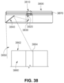
- FIG. 38 is an exposed side view of a modular FOV separator in accordance with the embodiment of FIG. 37 , including an angled mirror directing the optical path onto an underlying object under inspection;
- FIGS. 39 and 40 are top and bottom oriented perspective views of a modular FOV separator according to an exemplary embodiment
- FIG. 41 is a top oriented perspective view of an electronics-carrying core for the modular FOV separator of FIGS. 39 and 40 ;
- FIG. 41 A is a top oriented perspective view of the core of FIG. 41 showing modules (e.g. structured light projectors) attached to receptacles along a side face thereof;
- modules e.g. structured light projectors
- FIG. 42 is a bottom oriented perspective view of the core of FIG. 41 showing modules (e.g. distance sensors) attached to receptacles along a bottom face thereof;
- modules e.g. distance sensors
- FIG. 43 is a bottom oriented perspective view of a modular FOV separator and expander showing a four way modular core and a pair of opposing mirror arms;
- FIG. 44 is a bottom oriented perspective view of an FOV separator having the four-way core of FIG. 43 , and including four modular mirror arms in a crossed relationship at right angles to each other;
- FIG. 45 is a top oriented perspective view of the four-way core of FIG. 43 showing opposing component arms attached thereto, for performing ancillary functions;
- FIG. 46 is an exposed side view showing a FOV separator using a single, high resolution image sensor and optics to generate crossing FOVs for imaging both sides of an object under inspection, according to an exemplary embodiment
- FIG. 47 is another exemplary embodiment of a FOV separator generating crossing FOVs
- FIGS. 48 - 50 show a four-way FOV separator and expander using a plurality of mirrors to generate multiple FOVs for generally surrounding the exposed sides of an object under inspection;
- FIG. 50 is a diagram showing application of the 90-degree rule for configuring mirror modules in an FOV separator and expander according to various embodiments
- FIG. 51 shows a basic operative principle applied to the FOV separator(s) and expander(s);
- FIGS. 52 and 53 are respective top and side diagrams of an exemplary arrangement for roll balancing and crossing FOVs
- FIGS. 54 and 55 are respective top and side diagrams showing conversion of roll to tilt along an optical path in an exemplary arrangement
- FIGS. 56 and 57 are respective top and side diagrams showing the arrangement of FIGS. 54 and 55 for two optical paths associated with two optical axes of a camera assembly;
- FIGS. 58 and 59 are respective top and side diagrams showing conversion of roll to tile where the 90-degree rule of FIG. 51 is not applied in an exemplary arrangement;
- FIGS. 60 and 61 are respective top and side diagrams showing conversion of roll to tilt along an optical path, along with crossing FOVs in an exemplary arrangement
- FIG. 62 is an external perspective view of a FOV separator or expander with a single exemplary sensor and optics arrangement that can be employed with a rotating separating mirror assembly to adjust the partial FOVs defined thereby;
- FIG. 63 is an exposed perspective view of the camera assembly and mirror arrangement, including an adjustable, rotating separating mirror assembly for use in the arrangement of FIG. 62 ;
- FIGS. 64 and 65 are side views of the separating mirror assembly and associated deformable action and mounting arrangement, shown in a neutral and rotated orientation, respectively.
- FIG. 1 shows a vision system arrangement 100 in which a vision system or ID reader assembly 110 oriented at an acute angle with respect to a moving line represented by a conveyor 112 .
- the vision system 110 includes a camera assembly 114 adjustably mounted in a frame 116 .
- the camera assembly includes the camera base 118 and a lens 120 .
- the base 118 includes an internal sensor (described below), having a pixel array for acquiring grayscale of color image data.
- the size of the array is highly variable.
- the array can be a conventional rectangular (roughly square) array having a size of 1024 ⁇ 768 pixels.
- the camera base 118 can include an internal vision processor and ID (barcode) decoding circuit.
- the camera can transmit raw image data to a remote, interconnected (wired or wireless) processing device, such as a networked PC.
- a vision system process 130 locates and resolves IDs, and feeds the data to a decoding process that outputs ID information (block 132 ).
- the data can be transmitted using a wired or wireless connection to a processing device and/or a process, such as a label printer, alarm or gating system that directs motion of a conveyed object based upon the information contained in the ID.
- the imaged scene can be illuminated by an acceptable illumination unit or units.
- an exemplary illuminator 144 is mounted above the scene using a bracket (not shown) or other mounting arrangement.
- the illuminator(s) can be mounted separately from the reader assembly 110 as shown, and/or as an integral part of the assembly (for example as a ring illuminator arranged around the FOVE).
- the illuminator(s) are operatively connected to an illumination controller that can be triggered by the ID reader assembly 110 (e.g. the camera base processor) or by another processor (e.g. a PC interface).
- the lens 120 can be any acceptable lens type, such as a fixed-magnification or variable-magnification (zoom) lens.
- the lens mount can be a conventional C-mount, F-mount, etc., or a custom mount, or a fixed lens. Alternate lens types, such as liquid lenses can also be employed.
- the lens 120 is positioned to receive light from a field of view expander (FOVE) 140 fixedly mounted with respect to the camera assembly 114 using an illustrative L-shaped bracket 142 that is the front part of the frame 116 .
- FOVE field of view expander
- a variety of frame assemblies can be used to physically interconnect the camera assembly 114 to the FOVE 140 .
- the FOVE can be integrally attached to the camera base and/or lens so that is defines an integral unit.
- the camera and FOVE are mounted using a bracket arrangement (not shown), such as an overhead bracket, so that the scene is imaged appropriately for the scanning operation. While the camera assembly and FOVE are typically fixed as shown, and objects move through the associated field of view, it is expressly contemplated that the objects or subjects can be fixed, and the camera assembly and FOVE can move on an appropriate track or other structure. Thus, as defined broadly herein, the camera assembly with FOVE and the object(s) are in “relative motion” with respect to each other.
- That object 150 is represented, by way of example, by a box having a plurality of IDs (e.g. one-dimensional barcodes) 152 , 154 , 156 and 158 positioned at discrete locations across the width of the object 150 .
- the object 150 moves (double arrow 156 ) on the conveyor 156 with respect to a field of view 158 generated by the FOVE 140 .
- the field of view 158 is arranged to cover the width FOVW of the conveyor 112 and/or object 150 .
- the height FOVH of the field of view is arranged to image the area of the object expected to contain IDs.
- object can be taken broadly to comprise a plurality of objects arranged side by side across a width of a line.
- an object can be a longer structure (e.g. a web) having a multiplicity of IDs or other features of interest therealong.
- an ID-reading application can sometimes be more effectively implemented if the sensor defines 2048 ⁇ 384 pixels or 2048 ⁇ 768 (at a lower frame rate) instead of the standard 1024 ⁇ 768. That is, it can be desirable to provide a sensor that is N times as wide, and illustratively one-Nth as tall, as a standard unit.
- Such an arrangement can be particularly useful in reading the one-dimensional bar codes 152 , 154 , 156 and 158 in known widthwise orientation across the conveyor 112 , as depicted in FIG. 1 .
- a sensor with roughly square aspect ratio can be modified into a “virtual sensor” which is much wider and possibly narrower (but with the same overall number of pixels) so that a wide, but narrow strip across the field of view is imaged.
- this strip is imaged in a manner that is free of loss of the resolution per-unit-area of the object when compared to an unmodified sensor without (free of) the FOVE.
- the effect of the FOVE 140 of the illustrative embodiment is to provide the two depicted fields of view 160 and 162 that cover the width of the object 150 and/or conveyor 112 with a sufficient height to fully image an ID (barcode) within a given acquired image frame.
- the overlap region OR is variable and ensures that the largest expected feature is within one or both of the defined fields of view 160 , 162 .
- the size of the overlap region OR is larger than the largest ID (e.g. center ID 158 ) so that this feature is fully imaged.
- the camera base 118 includes a sensor 166 in optical communication with the lens 120 and FOVE 140 .
- the sensor is interconnected with on-board and/or remote processing components (not shown) as described generally above.
- the rear panel 167 of the camera base 118 includes various interface controls and connectors in an illustrative embodiment.
- the FOVE 140 in this embodiment consists of an outer shell 168 illustratively constructed from an appropriate metal, polymer or composite. It can include various ribs (e.g. crossing ribs 169 ) that stiffen and lighten the shell 168 .
- a transparent window 170 covers and seals the rear aperture 171 of the shell to allow light to pass into the lens 120 .
- the front end of the shell is covered by a front transparent window 172 that is secured by a front bezel 174 .
- the shell encases a support plate assembly 176 that extends along a bottom side of the shell and includes a reinforced upright plate that surrounds the aperture 171 (allowing light to pass therethrough), and is secured to the rear face of the shell.
- the support plate assembly 176 supports the mirrors employed to expand the field of view in accordance with the illustrative embodiment.
- the support plate assembly 176 secures a pair of opposing outer-extended mirrors 210 and 212 that each respectively extend from a position 226 and 218 near each side the rear aperture to a respective side edge of the shell ( 168 in FIGS. 1 and 1 A ).
- two, vertically stacked, crossing inner mirrors 220 and 222 reside on a mount ( 180 in FIG. 1 A ) centered about the optical axis OA.
- the inner mirrors' crossing line 310 ( FIG. 3 ) is arranged along the axis OA.
- the mirrors have a vertical tilt so the crossing ‘line” is an approximate region that is generally/approximately vertical and generally/approximately resides around the axis OA.
- various directional and orientation terms such as “vertical”, “horizontal”, “up”, “down”, “bottom”, “top”, “side”, “front”, “rear”, “left”, “right”, and the like are used only as relative conventions and not as absolute orientations with respect to a fixed coordinate, such as gravity.
- the outer mirrors 210 and 212 are directed to receive light from a scene through the front window ( 172 in FIG. 1 A ). In this embodiment they are each oriented at a respective acute angle AOM 1 and AOM 2 relative to a line (dashed lines 330 and 232 parallel to the axis OA) in FIG. 3 that generates the desired expanded, overlapping field of view at a given focal distance FD from the sensor image plane 320 (see also FIG. 4 ). As shown in FIG.
- the crossing inner mirrors 220 and 222 define, in essence a “beam splitter”, which reflects the light transmitted from the outer mirrors 210 and 212 into an overlapping wedge (frustum) 410 that is aligned with the axis OA of the lens and camera and substantially perpendicular to the sensor image plane.
- This is desirable in that ensure that light received from each field of view is relatively free of distortion when it reaches the sensor. That is, light that reaches the sensor at an angle can provide a distorted image that is moiré difficult to analyze and decode.
- the crossing inner mirrors 220 and 222 are each oppositely angled with respect to the axis OA at respective angles ACM 1 and ACM 2 .
- angles AOM 1 and AOM 2 are in a range of approximately 45 to 75 degrees, and typically 68 degrees, while angles ACM 1 and ACM 2 are typically in a range of 45 to 75 degrees and typically 68 degrees.
- the crossing inner mirrors of the beam splitter define substantially equal opposite angles with respect to the optical axis. Also, in an illustrative embodiment (referring to FIG.
- outer mirrors 210 , 212 each have a horizontal length OML of between 40 and 120 millimeters, and typically 84 millimeters, and a vertical height OMH of between 20 and 50 millimeters, and typically 33 millimeters.
- the crossing inner mirrors 220 , 222 illustratively have a horizontal length CIVIL of between 30 and 60 millimeters, and typically 53 millimeters, and a vertical height CMH of between 10 and 25 millimeters, and typically 21 millimeters.
- the overall horizontal span OMS of the outer mirrors 210 , 212 (referring to FIG.
- any mirror can be increased or decreased and their angles with respect to the axis OA can be varied as appropriate.
- the mirrors can be constructed from any acceptable specular material that produces the desired optical effect. For example, a silvered glass mirror or an equivalent polymer can be employed. Other specular materials, such as highly polished or coated metals can be used in certain embodiments.
- the outer mirrors 210 and 212 are positioned at a vertical offset with respect to each other, and relative to the overall height of the shell (See FIG. 1 A ). In this manner, each outer mirror 210 , 212 is aligned more vertically with its associated inner mirror, 220 , 222 .
- the offset distance ODM between the bottom edge 430 of the higher outer mirror 210 and the upper edge 432 of the lower outer mirror 212 is approximately 16 millimeters. This dimension can be varied in alternate embodiments depending, in part on the overall height of the outer mirrors and FOVE shell.
- the upper inner mirror 220 defines a tilt off the vertical (i.e. a vertical that is perpendicular to the axis OA shown by dashed line 180 ) that orients this mirror 220 tilt slightly downwardly and inwardly relative to the axis OA.
- the tilt is represented by an acute (slightly non-perpendicular) angle ATM 1 which is approximately 88 degrees (and more particularly 87.9 degree) in an illustrative embodiment.
- the lower inner mirror 222 tilts slightly inwardly and downwardly by an opposing angle ATM 2 of approximately is approximately 88 degrees (and more particularly 87.9 degrees) with respect to the axis OA in an illustrative embodiment.
- the overall geometry of the mirrors resolves the two side-by-side overlapping fields of view into a pair of slightly overlapping, strips that are received by the lens and sensor as a stacked pair of views.
- the stacked images are substantially axially aligned with the optical axis OA along the horizontal plane, and slightly angled with respect to the vertical plane (due to the tilt of the crossing mirrors) resulting in a relatively distortion-free image.
- the mirror arrangement of the FOVE in accordance with the exemplary geometry and dimensions described above, is generally rotationally symmetric with respect to the optical axis OA.
- FIGS. 5 - 7 show the resulting image received by the sensor based upon the optical arrangement of the FOVE according to the illustrative embodiment.
- the resulting image 500 in which the overall width of the field of view is represented by a ruler 510 includes a top portion 520 that constitutes the right side (with ruler inch-gradations 1-9) and a bottom portion that constitutes the left side (with ruler inch gradations 6-14).
- a narrow blended horizontal dividing line is depicted between the image strips 520 and 530 .
- the upper image strip 520 includes an ID 550 within its full field of view.
- the lower image strip 530 also includes a separate ID 552 within its full field of view. Both IDs provided across a wide field of view have been effectively imaged and the overall height dimension has been reduced to minimize excess information in the height direction while still providing sufficient space to fully image the ID. As described above, this narrowed height serves to reduce the number of image frames that can capture the same ID, thereby reducing the risk of double readings of the same object.
- the horizontal overlap is represented by the occurrence of inch gradations 6-9 in both the upper and lower image strips 520 and 530 , respectively. This distance (about 3-4 inches) is sufficient to ensure that a centered ID of a certain size (e.g. 2-3 inches) is fully captured in at least one of the image strips 520 , 530 .
- An example of a centered ID 610 residing in the overlap region of each strip is shown in the diagram 600 of FIG. 6 . This ID 610 is positioned similarly to the ID 158 in FIG. 1 . In the diagram of FIG. 6 , the ID 610 occurs in the left hand overlap region 622 of the upper strip 620 . Likewise, in the lower strip 632 , the centered ID 610 occurs in the right hand overlap region 632 . As described, this region ensures that an ID will fall fully into at least one of the two strips so as to ensure positive identification by the vision system.
- FIG. 7 shows a conventional camera sensor 166 as described above.
- the transmitted light from the FOVE reaches the sensor, through the lens so as to define the depicted upper strip 710 and lower strip 720 , in which the right side is radiated on the upper strip to be captured by its respective pixels, while the left field is radiated onto the lower strip to be captured on its respective pixels.
- a relatively narrow vertical overlap band can be defined at the strip boundary 730 , where both the left and right fields are deposited. This information can be discarded by the vision system process.
- the optics of the mirrors can be arranged to define a dark band over a few rows of pixels to avoid confusion.
- the FOVE allows a sensor with an M (width) ⁇ N (height) pixel array to operate as a narrower 2M ⁇ N/2 sensor with no loss of resolution within the imaged area.
- FIG. 8 describes a basic procedure 800 for locating and decoding IDs (or other features of interest) across an expanded width using a vision system with an FOVE according to an illustrative embodiment.
- the system acquires an image frame, which includes an upper strip and a lower strip (step 810 ). While not shown, image acquisition can be triggered based upon a presence sensor (e.g. a photodetector, line encoder or vision-system based detector) that senses and/or computes when an object comes into the field of view of the vision system. At such time the system begins acquiring image frames of the object. Each acquired image is then passed to an ID feature search and analysis process 820 .
- a presence sensor e.g. a photodetector, line encoder or vision-system based detector
- the ID feature search/analysis and decoding application(s) i.e. software consisting of a non-transitory computer-readable medium of program instructions and/or hardware
- the search for ID candidates can also be handled by a separate process or processor from decoding (which can be handled by a decoding DSP).
- decoding which can be handled by a decoding DSP.
- the image can be processed free of any need to “stitch together” portions of it so as to provide a complete ID. Rather, a complete ID is expected to reside in some portion of the overall image and can be located by directly searching the image.
- processors can be implemented using electronic hardware, software consisting of a non-transitory computer-readable medium of program instructions, or a combination of hardware and software.
- the overall procedure 800 returns via decision step 830 to await the next acquired image frame in step 810 . Conversely if any IDs are located in the image frame, then the decision step 830 branches to perform further process.
- An optional decision step 840 can determine whether the same ID exists (completely) in both the upper and lower overlap region. If so, it can filter the data to pass only one instance of the ID to speed processing (step 850 ).
- the procedure 800 can branch back to step 810 to await the next set of image data for search and analysis (branch).
- branching back to step 810 can occur later in the process.
- the procedure 800 After providing ID data, the procedure 800 then decodes the located IDs using conventional or customized processes in step 860 . The decoded data is then output to be stored and/or used by further processes in step 870 .
- an arrangement 900 allows a wide line 910 to be imaged free of loss of resolution within the imaged area.
- two vision system camera assemblies 920 and 922 are provided in a side-by-side arrangement at an appropriate widthwise spacing CWS between respective optical axes OA 1 and OA 2 .
- Each camera assembly 920 , 922 includes a respective FOVE 930 , 932 , which can be constructed and arranged in accordance with the embodiment of FIGS. 1 - 4 A described above.
- Each camera assembly 920 , 922 and respective FOVE 930 , 932 is mounted on an appropriate bracket assembly (not shown).
- the FOVE 930 defines a widened overall field of view with a left field 940 and a right field 942 , which appears on the camera sensor as a pair of stacked strips as described above.
- the two fields 940 , 942 include an overlap region OR 1 sized to ensure inclusion of the largest feature of interest therein.
- the adjacent FOVE 932 defines a widened overall field of view with a left field 950 and a right field 952 , which appears on the camera sensor as a pair of stacked strips as described above.
- the two fields 950 , 952 also include an overlap region OR 2 that is sized to ensure inclusion of the largest feature of interest therein.
- the spacing CWS between cameras 920 , 922 is chosen to generate a third overlap region OR 3 that is sized and arranged to ensure that the largest feature of interest resides fully within at least one adjacent field of view 942 , 950 of a respective camera 920 , 922 .
- a procedure 800 can be carried out within the processor associated with (or operatively connected with) one of the cameras using a master-slave interconnection 970 between cameras (commercially available on a variety of camera units, such as certain units manufactured by (Cognex Corporation).
- a master-slave interconnection 970 between cameras commercially available on a variety of camera units, such as certain units manufactured by (Cognex Corporation).
- acquisition of concurrent image frames in both the master (M) and slave (S) cameras is triggered by the master (camera 920 herein designated M) and handling of image data is controlled by the master.
- both the processors of the master and the slave can operate to locate and analyze IDs or other features of interest.
- One or both of the cameras are used to output resulting data (block 980 ) as described above.
- a wider field of view than that obtained with the FOVE of FIGS. 1 - 4 A can be achieved using a single camera assembly 1010 in the arrangement 1000 of FIG. 10 .
- the FOVE 1020 (with shell removed for clarity) includes four discrete outer mirrors, with two positioned on each side of the optical axis OA 1 A 1030 , 1032 and 1034 , 1036 .
- Each mirror is oriented at a discrete angle with respect to the optical axis, with the outermost mirror pair 1030 and 1034 having a smaller angle than the innermost mirror pair 1032 and 1036 .
- each of the outers mirrors 1030 , 1032 , 1034 and 1036 are each highly variable and in general are constructed and arranged to define the four fields of view 1050 , 1052 , 1054 and 1056 , respectively that span the width of an expanded field of view FOVW 1 .
- Adjacent fields of view have appropriately sized overlap regions for reasons described above. That is, adjacent fields 1050 and 1052 define overlap region OR 1 A, fields 1052 and 1056 define overlap region Or 2 A and fields 1056 and 1054 define overlap region OR 3 A.
- the outer mirrors can be located at higher or lower positions vertically with respect to the optical axis OA 1 A.
- a “beam splitter” That can consist of four stacked, angled and vertically tilted mirrors arranged similarly to that of the FOVE described in FIGS. 1 - 4 A .
- the resulting split image provides four stacked strips upon the sensor of the camera 1010 .
- the strips divide the image of an M ⁇ N sensor into a 4M ⁇ N/4 wide image.
- the arrangement of the outer mirrors and beam splitter mirrors allows each image strip to be substantially aligned (along the horizontal plane) with the optical axis for minimum distortion thereof.
- This approach is effective so long as the line speed is slow enough and/or the frame rate of the camera is high enough to ensure a relatively complete ID or other feature of interest can be acquired in the relatively narrow-height strip of the expanded field of view.
- an FOVE can be implemented using a moving mirror arrangement in optical communication with the camera assembly.
- a polygonal, rotating (curved arrow 1112 ) mirror 1110 can be employed to provide a sequence of full resolution images across the width of the object having a wider profile that the original field of view than the camera assembly 1120 .
- the rotation is along an axis 1116 generally perpendicular to the horizontal plane of the field of view though the optical axis OA 1 B.
- Each reflecting surface on the polygonal mirror is typically (but not necessarily) substantially perpendicular to the horizontal plane and parallel to the axis of mirror rotation 1116 .
- a sequence of images 1130 , 1132 , 1134 is acquired in (for example) a sequence of images to be taken which look at neighboring regions of the overall width of the scene.
- frame rate information 1140 can be transmitted from the camera assembly to synchronize operation of the mirror drive motor 1150 under control of a motor control circuit 1160 of appropriate configuration.
- a stepper motor can be used to accurate step through a sequence of positions that place each of the mirror surfaces 1180 at an appropriate angular orientation to reflect back an optically aligned (i.e. aligned with the camera optical axis OA 1 B) image of a portion of the width.
- the mirror has a regular polygon shape and the angular orientation of each surface (angle ARM) varies upon acquisition of each image frame so as to achieve a sequence of images across the width of the scene.
- Frame 1 is taken at a 38-degree relative angle ARM
- frame 2 is taken at a 45 degree relative angle ARM
- frame 3 is taken at a 52 degree angle.
- the polygon is irregular ad the motor steps stop at regular degree intervals, in synchronization with the frame rate so that each step exposes a slightly differently angled face of the polygon to the optical axis. This synchronization essentially generates an approximately constant pattern of varied angular orientations in a sequence.
- Each image can define an appropriate overlap region along an adjacent edge with another image, the size of which in the widthwise direction is sufficient to ensure that an ID or other feature of interest fully resides within the overlap region of one of the images.
- the overall width of the field of view is highly variable.
- Each image can be independently search and analyzed for IDs or other features without regard to other images in the sequence (i.e. free of the need to stitch together the overall image).
- the motion of the object in the drive direction should not affect the ability of the system to resolve any IDs so long as the full width of the object can be imaged while an ID remains within the height of at least one of the images.
- the mirror can be slightly asynchronous with frame rate and a large sequence of images at a number of differing orientations can be acquired in a possibly random sequence.
- a boundary can limit the maximum field of view to the desired width so that only light from the object within the defined field reaches the camera.
- an oscillating mirror (not shown) can be used as a “moving” mirror.
- the oscillating mirror can be a micro mirror that moves (rotates along an axis perpendicular to the horizontal plane) between different angular orientations with respect to the camera optical axis so that different portions of the overall field of view are imaged.
- the motion of the mirror can be synchronous or asynchronous with respect to the object.
- This vision system 1200 includes a vision system camera assembly having an acceptable size, shape, lens arrangement and performance characteristics.
- a camera assembly is shown and described in commonly-assigned U.S. patent application Ser. No. 13/645,173, entitled SYMBOLOGY READER WITH MULTI-CORE PROCESSOR, by Laurens Nunnink, et al, filed on even date herewith, and commonly assigned U.S. patent application Ser. No.
- This camera assembly 1210 optionally employs an auto-focusing lens based upon a commercially available liquid lens component. The lens assembly is described further below.
- the camera is attached to the FOVE assembly 1212 by an intermediate coupling assembly 1214 that aligns the FOVE with the optical axis of the camera assembly.
- the coupling assembly 1214 includes an L-shaped bracket 1220 that can be constructed from a sturdy material, such as aluminum alloy.
- the bracket 1220 includes a vertical face 1222 engaging the camera using, for example threaded fasteners (described further below) that seat into threaded holes in the front face 1224 of the camera assembly 1210 . Standoffs/spacers can be used to space the vertical face 1222 from the camera front face at a desired spacing distance.
- the vertical face 1222 of the bracket 1220 is secured by fasteners ( 1310 in FIG. 13 ) to four metal (e.g.
- the coupling 1214 thereby provides a rigid alignment between the camera assembly 1210 and FOVE 1212 along the camera optical axis CA.
- the posts 1226 allow several centimeters (e.g. approximately 4-5 centimeters) in length (along the optical axis) of clearance to access the lens shroud assembly 1240 .
- This length is longer than a standard C-mount lens.
- the shroud assembly is constructed from an aluminum or polymer tube and serves to cover the underlying lens assembly against dust and other environmental contaminants. This provides a fully sealed optical system between the front transparent window 1242 of the FOVE 1212 and the front face 1224 of the camera assembly 1210 .
- the shroud is movable (double arrow 1244 ) between a position in which it sealingly engages the bracket vertical face 1222 and a rear flange 1250 on the rear of FOVE housing 1230 .
- the barrel shroud 1240 includes seals (e.g. lubricated natural rubber O-rings) on each end that each seal against the inner perimeter of the port formed in the vertical face 1222 and flange 1250 , respectively.
- the shroud assembly 1240 is attached to a slider 1260 that is secured to the shroud's perimeter.
- the slider 1260 includes two opposing bushings (constructed from a low-friction material such as Teflon or Delrin), which allow for ease and accuracy of movement of the shroud assembly along the posts.
- the shroud assembly 1240 can be moved out of the depicted sealed and covered arrangement to a position in which it telescopes into the rear end of the FOVE housing, thereby revealing an underlying camera lens assembly (having a smaller diameter than the inner diameter of the shroud).
- the lens can be adjusted for focus, aperture, etc. by moving conventional adjustment rings thereon.
- the shroud is constructed to cover a C-mount lens or smaller, but other types of lens can be accommodated with appropriate sizing of the shroud 1240 .
- the bracket 1220 also includes a bottom plate 1270 that is adapted to secure a forwardly extended bracket 1272 as an option.
- This bracket allows the removable mounting of (for example) a bar illuminator 1274 using a variety of attachment techniques including clips, fasteners, and the like.
- the illuminator (or multiple illuminators) 1274 can be electrically connected with a triggered power source carried on the camera assembly or an external device.
- a differing (smaller) camera assembly 1320 is shown mounted to the vertical face 1222 .
- This camera assembly employs appropriate mounting fasteners and accompanying holes (not shown) to be joined to the coupling 1214 .
- a series of crossing ribs 1330 also described above on the rear side of the housing 1230 .
- These ribs 1330 are disposed within recesses on each side of the housing 1230 .
- the ribs can be between approximately 1 and 4 centimeters in height and approximately 2 to 5 millimeters thick.
- These ribs 1330 support each angled mirror carrying surface 1340 and 1350 .
- each surface 1340 , 1350 maintain a relatively stable compound tilt angle with respect to the camera axis (the illustrative tilt geometry being described above with reference, for example, to FIG. 3 ).
- the housing is constructed from a unitary member using a molding technique, such as injection molding with a durable, stable material, such as commercially available glass-filled polycarbonate. In particular this material advantageously minimizes dimensional tolerance due to shrinkage during the molding process.
- the front rim 1360 of the housing is attached by fasteners that pas into a series of bases 1362 .
- a series of unitary stiffening rips can extend rearwardly from each base 1362 (or another location) along the top (and bottom—not shown) of the housing 1230 . To provide further rigidity to the unit.
- Other molded shapes and structures can be provided to the exterior and/or interior of the housing to achieve desired structural and/or aesthetic effects.
- FIGS. 14 - 20 variously detail a further embodiment of an FOVE for use in a vision system as contemplated herein.
- FOVEs of FIGS. 1 and 12 are adapted for a field of view (e.g. conveyor width) in the range of approximately 15 inches, it is often desirable to image wider scenes (e.g. approximately 25 inches).
- space can be more limited and thus the use of a long and wide FOVE attachment can be undesirable—for example when imaging the side of a box on a conveyor line.
- the ability to rotate the optical path so that the field of view is at a right angle to the elongated length of the camera assembly and associated FOVE can be advantageous.
- this can allow the camera assembly and FOVE to extend lengthwise along the running direction of the conveyor line taking up less lateral space.
- a vision system 1400 employing a camera assembly 1210 (described above) and an FOVE 1410 according to an illustrative embodiment.
- the FOVE 1410 consists of a mirror enclosure 1420 , an extension tube 1430 and a coupling 1440 , similar to the coupling 1214 described above.
- the camera assembly is shown rotated (curved arrow R) 90 degrees with respect to the above-described embodiments.
- the mirror arrangement (described below) of the FOVE 1410 is oriented so that the field of view is rotated 90 degrees (curved arrow OR) with respect to an axis AP taken perpendicularly through the camera axis OA 3 and parallel to the horizontal plane.
- the camera axis OA 3 is approximately parallel to the plane (as depicted) imaged scene 1450 and the view angle of the FOVE is directed vertically onto the scene. It is contemplated that the camera axis can be non-parallel to the scene and the view angle is off the vertical in alternate implementations. As shown, a pair of overlapping fields of view 1452 and 1454 is provided. The degree of overlap (OL) is variable, as described further below.
- the mirror arrangement 1510 consists of a pair of outboard angled mirrors 1520 and 1522 that are oriented at an acute angle AM 1 with respect to the horizontal plane HP (parallel to the camera axis OA 3 ). This angle can be approximately 45 degrees in an embodiment.
- light is reflected by each mirror 1520 , 1522 from a portion of the underlying scene toward each of a pair of vertically arranged inboard mirrors 1530 , 1532 , respectively.
- These mirrors define a “beam splitter” with a vertically oriented V-shape centered through the axis OA 3 as shown.
- the outboard mirrors 1520 , 1522 have a height HM 1 of approximately 45 millimeters and a length LM 1 of approximately 192 millimeters, but these measurements are highly variable in alternate embodiments.
- the inboard mirrors 1530 , 1532 each have a height HM 2 of approximately 36 millimeters and a length LM 2 of approximately 100 millimeters. Again, these measurements are highly variable in alternate embodiments.
- the overall length of the mirror enclosure is approximately 25 inches.
- the mirrors 1520 , 1522 , 1530 and 1532 reflect light from the scene (fields of view 1542 and 1454 ) into two, respective, 90-degree rotated strips 1542 and 1544 that are horizontally stacked. These stacked strips 1542 , 1544 are projected onto the camera imager 1540 as depicted.
- the geometry of the mirrors generates a horizontal stacking, rather than a vertical stacking of strips as described in the above embodiments (i.e. FIG. 1 and FIG. 12 ).
- the camera assembly is rotated about the axis OA 3 by 90 degrees (curved arrow R in FIG. 14 ).
- the direction of rotation can be clockwise or counterclockwise.
- the camera assembly is free of rotation and the strips are projected in horizontal stack.
- the vision system and decoding processes are adapted to operate on such horizontal stacks in such alternate embodiments.
- the FOVE mirror enclosure 1420 includes a bottom window 1610 that covers the outboard mirrors 1520 , 1522 .
- the mirror enclosure 1420 is illustratively constructed from a metal extrusion (e.g. aluminum alloy), or another acceptable material (e.g. polymer, composite, etc.).
- the cross section of the enclosure 1420 defines an approximately rectangular “tube” with a slightly bowed front 1620 , mainly for aesthetics.
- the extruded enclosure 1420 also provides for full-length keyway slots 1630 , 1640 respectively along (at least) the front 1620 and top 1622 .
- These keyway 1630 , 1640 slots allow for the attachment of accessories, such as one or more illuminators (e.g. bar illuminators as described above).
- the slots also enable the enclosure to be secured to a mounting bracket or other supporting component.
- One or more headed bolts or threaded studs of appropriate size and shape can be passed into a slot to facilitate a connection.
- a T-shaped rail can be passed into the slot.
- the mirrors 1520 , 1522 , 1530 , 1532 are mounted on a mirror mounting plate 1720 ( FIG. 17 ) that is secured by threaded fasteners to the rear face of the enclosure 1420 .
- Alternate attachment techniques e.g. adhesive, clips, etc.
- the enclosure includes a pair of ports 1660 and 1662 that allow light to pass into the mirrors 1520 and 1522
- the ports can be formed in the originally solid bottom wall of the extrusion in a variety of manners (e.g.
- the ports 1660 and 1662 are separated from the ends by edge sections 1672 , and are separated from each other by a central bridge section 1670 .
- the central bridge section underlies the vertical V-shaped inboard mirror assembly ( 1530 , 1532 ), and thus, is fee of interference with the view of the scene.
- the opposing ends of the mirror enclosure 1420 are each capped with gasketed end cover plates 1680 , 1682 constructed from metal (e.g. steel, aluminum alloy, etc., a polymer or a composite.
- the cover plates 1680 , 1682 are removably secured in place by fasteners 1684 that are threaded into holes formed in corner beads 1686 of the extrusion.
- corner beads 1686 also serve to reinforce the unitary joints between sides of the enclosure. Note that the profile of each keyway slot 1630 , 1640 is carried through the perimeter of the cover plate 1680 , 1882 so that an item can be slid on or off the enclosure while the cover plates are installed.
- the extension tube 1430 is provided to (in combination with coupling 1440 ) afford sufficient focal distance to the assembly (see rays 1730 ).
- This tube 1430 also comprises an extrusion, typically formed from aluminum alloy. Similarly to the mirror enclosure 1420 , other materials are expressly contemplated for this component.
- the extension tube 1430 is secured to adapter plates 1740 , 1742 at each end using threaded fasteners. An O-ring seal can be provided between each plate and the confronting end of the tube 1430 .
- the adapter plate 1740 is, in turn secured by fasteners that pass from the inside of the extension tube 1430 into threaded holes in the enclosure 1420 .
- Each of the adapter plate 1740 , enclosure 1420 and mirror mounting plate define an aligned central orifice 1750 sufficient in size to allow light reflected from the mirrors to pass there through free of obstruction.
- the opposing extension tube adapter plate 1742 located adjacent to the coupling 1440 , is also secured to the extension tube end by fasteners and includes a sandwiched O-ring seal. This plate is secured to pour posts 1690 within the coupling 1440 that provide support between the extension tube 1430 and the camera assembly 1210 . With reference also to the more detailed view of FIG. 18 , the posts 1690 are secured to the adapter plate 1742 by threaded fasteners 1810 that reside within the interior of the extension tube.
- the posts 1690 movably (double arrow 1820 ) support a slider 1691 that engages a sliding lens shroud 1692 .
- O-rings 1830 , 1832 are embedded within the inner circumference of the adapter plate 1742 and the opposing vertical face 1695 of the L-shaped bracket 1696 .
- This bracket 1695 assists in supporting the overall assembly to a mounting structure, generally via fasteners attached to the horizontal face 1698 .
- the bracket 1696 also provides a common connection between the camera assembly 1210 and the FOVE 1410 via its vertical face 1695 .
- the lens shroud 1692 can be slid forwardly out of the depicted sealed position to reveal the lens 1697 (shown in phantom as an exemplary lens type).
- the vertical face 1695 is formed with a stop shoulder 1840 that defines the central orifice 1842 . This shoulder prevents further forward movement of the shroud toward the camera assembly after it is sealingly engaged.
- a rear stop 1844 is also provided on the front end of the shroud to engage an inner face of the adapter plate 1742 . The forward slidable movement of the shroud passes it into the interior of the extension tube 1430 until the slider engages the exterior wall of the adapter plate 1742 . This should provide ample room to access the lens 1697 for adjustment and/or service.
- the bracket vertical face 1695 is attached to the camera assembly in a manner described generally above using fasteners that engage threaded holes in the camera's front face and standoffs/spacers 1699 that provide an appropriate gap.
- the coupling 1440 is similar or identical in size, shape and construction to the coupling 1214 described above ( FIGS. 12 and 13 ). Overall, the extension 1430 and coupling 1440 define a length LEC of approximately 254 millimeters. This affords a useful field of view of approximately 25 inches in width depending on desired resolution.
- the construction of the FOVE 1410 is shown and described.
- the mirror enclosure 1420 with window 1662 is joined via a gasket 1910 to the adapter plate 1740 by fasteners 1912 .
- the adapter plate 1740 is joined to the confronting end of the extruded extension tube 1430 by fasteners 1914 , which compress an O-ring 1916 therebetween.
- a set of name plates or other informational decals 1920 can be provided to the sidewalls of the extension tube 1430 as an option.
- the opposing end of the extension tube 1430 is secured to a confronting face of the adapter plate 1742 by fasteners 1921 , also sandwiching an O-ring 1922 .
- the posts 1690 are secured to the adapter plate 1742 by above-described fasteners 1810 .
- the remainder of the coupling components are described above, with fasteners 1930 interconnecting the posts 1690 to the vertical face 1695 of the bracket 1696 .
- Fasteners 1940 in combination with a gasket 1950 and standoffs 1699 , secure the bracket vertical face 1695 to the camera assembly 1210 .
- the mirror enclosure is shown with the mirror mounting plate 1720 removed. It can be slid into and out of the enclosure interior when at least one cover plate (e.g. plate 1682 ) is removed.
- a gasket 2010 is also provided to seal the joint between the enclosure and the cover plate.
- the mounting plate 1720 is illustratively secured within the housing by fasteners 1970 ( FIG. 19 ) that pass through the rear side of the enclosure 1420 , and into threaded holed in the mounting plate 1720 .
- the mounting plate supports L-shaped brackets 2020 and 2022 that carry the respective outboard mirrors 1520 and 1522 .
- An inner triangular bracket assembly 2030 is attached to the mounting plate 1720 , suspended over the orifice 1750 .
- the orifice 1750 has an elongated aspect ratio that accommodates the length of the vertical mirror arrangement.
- the FOVE of this, or other embodiments herein can be adapted to assist in lens auto-focus operations where the lens 1697 is based upon a liquid lens or other varioptic principle.
- Such auto-focus lenses can be interconnected to an interface on (for example) the front face of the camera assembly via a cable/link 1980 (see FIG. 19 below) that powers the lens based upon a focus control process 1982 .
- a focus control process can operate based upon known techniques (e.g. determining the sharpness of image edges and readjusting until the optimal sharpness is achieved).
- a small fiducial can be applied to a known position on the FOVE in a location near an edge of the image where it is less likely to interfere with runtime image acquisition.
- various optional fiducial locations are shown including the FOVE window 1610 (fiducial F 1 ), the outboard mirror (fiducial F 2 ) and/or the inboard mirror (fiducial F 3 ).
- Other locations along the optical path can also be provided with appropriate marks or fiducials.
- Fiducials can be placed in a non-critical region of an image or can be provided to image in a wavelength that is only visible under certain illumination (e.g. near-IR) that is discrete from runtime image wavelengths. The focus process can discern the fiducial from the runtime image using a variety of techniques.
- FIG. 1 One form of fast-operating liquid lens assembly that can be employed in conjunction with the system and FOVE according to the various embodiments herein (i.e. FIG. 1 , FIG. 12 and FIG. 14 ) is the EL-6-18-VIS-LD membrane-based liquid lens available from Optotune AG of Switzerland. In addition to high speed operation, this lens defines, illustratively, a 6 millimeter aperture making it highly suitable for wider-area, high-speed operations.
- the illustrative variable lens package is sized 18 ⁇ 18.4 ⁇ 8.9 (thickness) millimeters. Control current is between approximately 0 and 200 mA. Response time is typically less than 2 milliseconds and settling time is typically less than 10 milliseconds.
- the overall lens assembly provides a field of view of approximately 20 degrees and a focal tuning range between 60 millimeters and infinity.
- the EL-6-18-VIS-LD is a shape-changing lens. It consists of an injection-molded container, which is filled with an optical fluid and sealed off with an elastic polymer membrane. The deflection of the lens is proportional to the pressure in the fluid.
- the EL-6-18 employs an electromagnetic actuator that is used to exert pressure on the container. Hence, the focal distance of the lens is controlled by the current flowing through the coil of the actuator. This distance decreases with decreasing applied current.
- FIG. 17 A schematically depicts the liquid lens assembly 1692 , which includes the liquid lens unit 1780 having associated cable 1782 . This cable 1782 is connected to a connector on the camera assembly. A rear lens 1784 is provided.
- a camera mounting base (for example, a C-mount base) 1786 removably interconnects the assembly to the camera assembly.
- the vision process can include a stitching process that searches for a partial features (partial symbols or codes) in each of the two images 2110 , 2112 generated by the FOVE and captured in the overall image frame 2120 within the imager.
- the images 2110 and 2112 are handled by a stitching process 2130 within the overall vision process, which searches for code features in each of the two images—typically at the boundary separating each of the images in the field of view.
- the stitching process 2130 attempts to assemble (stitch) a single code image from the partial code images, and then decode this assembled code image.
- the stitching process attempts to decode each of the two partial codes separately and assemble the (e.g. alphanumeric) results into a single sequence.
- the goal of stitching is to generate a single set of results 2140 from two (or more) images provided by the FOVE to the imager.
- the images 2110 and 2112 can be provided at differing acquisition times—for example in a sequence of image frames as the object passes through the scene on a conveyor. This is desirable where a code is somewhat long and moves through the field of view over a number of capture cycles.
- FIG. 22 A further optional arrangement is shown in FIG. 22 , in which a pair of vision systems 1400 in accordance with FIG. 14 above are mounted in a side-by-side arrangement to allow reading of a wider field of view.
- the two FOVEs 1410 are mounted on overhead posts 2210 (shown in phantom), which engage the top keyway slot 1640 of each FOVE housing.
- Each system 1400 also includes a rear post (or other mounting structure) 2214 that is attached to the bracket 1696 (described above) adjacent to the camera assembly. This arrangement provides a stable three-point mounting structure.
- a variety of alternate mounting arrangements can be employed including arrangements that engage other keyway slots (e.g. front slots 1630 ).
- a connector 2216 (shown in phantom can be used to interconnect the two FOVE units.
- This coupling can be a variety of widths depending upon the desired overlap in fields of view between separate FOVEs.
- the coupling can engage the keyway slots 1630 , 1640 . While shown at a spacing between each other in FIG. 22 , in various embodiments, the FOVEs can be closely butted together.
- the two systems 1400 are tied together by a cable or other link 2220 that allows for coordinated operation of image capture, illumination, image processing and other functions.
- the processes can be carried out in parallel in each vision processor (i.e. in each camera assembly) with appropriate signals passed between units to coordinate operation.
- the arrangement can function in a master-slave mode with one of the systems directing triggers, image processing and/or other functions.
- the lower front keyway slot 1630 of each system 1400 includes a mounted bar illuminator (also shown in phantom). These can be interconnected with a trigger/power source on the associated system camera assembly or with an external device.
- the resulting field of view is composed of four overlapping fields of view 2250 , 2252 , 2254 and 2256 , with overlap regions 2260 , 2262 and 2264 .
- Features within central overlap region 2262 can be read using one or both of the vision processors and appropriate links ( 2220 ) between camera assemblies.
- Another optional process 2300 detailed in FIG. 23 entails measurement of distance to an object or scene by determining the size of the overlap between discrete fields of view.
- the distance to the object or scene DS can vary, causing a variation in the width OL of the overlap region between fields 1452 and 1454 and the width of the corresponding non-overlap region NOL in each field 1452 , 1454 .
- the vision process can compute distance to the object based upon the measured overlap in the imager versus the overall size of the image (steps 2310 and 2320 ), and use this to adjust focus if required to obtain a decodable image (step 2330 ).
- Determination of overlap entails a determination by the vision process of the point along the width in each image strip where features (contrasts) are duplicated. This can be accomplished using a variety of conventional pattern matching tools. This technique can occur with relative speed and can employ subsampled images (i.e. images with a lowered or sparse pixel resolution (e.g. using down-sampling of the full-resolution image).
- FIG. 14 A the layout of the image 1460 generated by the arrangement of FIG. 14 is depicted.
- the two image (partial) fields of view IFOV 1 and IFOV 2 include overlap regions 1466 .
- FIG. 24 is a diagram showing two (partial) fields of view FOV 1 and FOV 2 of the scene at a distance d from focal points 2410 , 2412 . Likewise, two corresponding (partial) image field of vies IFOV 1 and IFOV 2 are depicted in FIG.
- a feature FE e.g. a recognizable code
- FOV 1 and FOV 2 A feature FE
- IFOV 1 and IFOV 2 A feature FE is present in each field of view FOV 1 and FOV 2 and appears at a relative position in each of the partial images IFOV 1 and IFOV 2 , which range between an arbitrary width position of ⁇ 1 and +1, with 0 at the center of each partial image.
- the following process steps enable determination of distance d:
- each partial field of view e.g. FOV 1 and FOV 2
- the illustrative stationary-mirror-based FOVEs illustratively direct the optical path of each partial field of view through at least two mirrors—with four or more total mirrors employed to generate two partial fields of view.
- the stationary-mirror-based FOVEs of the illustrative embodiments are characterized in that the (focused) optical path length for each partial field of view is similar or identical.
- the respective focal planes are similarly parallel.
- the illustrative FOVEs are generally optimal in their arrangement and function for applications in which relatively flat, wide objects should desirably remain in focus for imaging—such as large cartons and boxes.
- this arrangement desirably enables side-by-side placement of multiple camera assemblies with attached FOVEs as shown in FIGS. 9 and 22 .
- the overlap between adjacent, side-by-side vision system's fields of view can be defined similarly to the internal overlap with each discrete system, making the processing of data between adjacent systems more straightforward.
- FIGS. 25 and 26 show an overview of a vision system 2500 for use, for example, with ID-reading applications, such as shipping logistics, according to an illustrative embodiment.
- the arrangement 2500 includes a vision system camera 2510 according to any appropriate configuration as described/contemplated herein, and generally contemplated by those of skill.
- the vision system camera includes an on-board or remote vision system processor and associated process 2512 .
- a variety of associated vision system modules and tools can be provided including those employed in ID reading 2514 .
- the camera 2510 is mounted on the FOVE housing 2520 .
- the FOVE housing 2520 can be constructed in a manner similar to other housings described herein from a composite (e.g. epoxy glass, glass-filled nylon, etc.), polymer (e.g. thermoplastic, polycarbonate, acrylic, etc.) and/or metal (e.g. aluminum alloy, magnesium).
- the housing can be constructed using casting, molding, extruding, machining-from-stock, or a combination of techniques.
- the FOVE housing 2520 includes a camera mounting base 2522 and a rectangular-cross section, frustum-shaped, extension tube 2524 that (as described below) includes mounting fixtures for attachment to an overhead assembly within a runtime environment.
- the extension tube 2524 interconnects to the mirror enclosure portion (or “mirror enclosure”) 2526 of the overall housing 2520 .
- the mirror enclosure bends received light (rays 2530 ) through approximately 180 degrees.
- a further remote mirror (represented by dashed line 2550 ) bends the light rays 2532 through another right angle from the imaged scene 2540 —a total of approximately 270 degrees from the imaged scene 2540 to the camera assembly 2510 .
- this remote mirror 2550 has a height of approximately 100 millimeters and a width of approximately 360 millimeters for the depicted arrangement. Size of the remote mirror 2550 can vary based upon the lengths DR 1 and DR 2 as well as the desired width of the field of view WFOV.
- the remote mirror 2550 can be constructed from any acceptable reflecting surface and associated mounting fixtures. In the depicted embodiment it is mounted at an angle (ARM 1 in FIG. 25 ) of approximately 40-50 degrees with respect to the horizontal (e.g. the plane of a conveyor, motion stage or other platform 2542 (shown in phantom) on which an object is placed/transported relative to the imaged scene) and/or with respect to the adjacent FOVE optical axis.
- angle ARM 1 of the remote mirror with respect to the horizontal/FOVE optical axis is typically less than or greater than 45 degrees and the incident angle of the optical axis between the object and remote mirror is often non-perpendicular.
- This non-perpendicular orientation both: (a) reduces unwanted glare and reflections (e.g. when a scanned object exhibits specularity); and (b) allows an improved viewing angle in certain scanning arrangements—for example, where the camera is adapted to scan two sides (e.g. front and side, or top and side) at once.
- the angle ARM 1 of the remote mirror 2550 with respect to the horizontal/FOVE optical axis can be between approximately 20 and 50 degrees, and the resulting angle of the adjacent optical axis between the remote mirror and object can be between approximately 40 and 100 degrees.
- a calibration object 2560 is shown located on the platform, and is imaged by the camera through the FOVE arrangement.
- the angled mirrors within the mirror enclosure 2526 define an extended overall (in the width direction) field of view WFOV with two overlapping fields, each projected on a portion of the camera imager in a manner described generally above.
- the overlap region OLR 2 can vary and the vision system processor is adapted to identify and read image data appearing within the overlap region appropriately (as described generally above).
- the size of the overlap region and overall field of view are each highly variable and dependent, in part, upon the resolution desired for features (e.g. IDs) on a runtime object being imaged.
- the arrangement 2500 allows for a relatively small/low height placement of the vision system with the mirror exclusively located in an overlying position within the inspection area.
- the geometry of the FOVE enables a relatively wide viewing area WFOV (for example between 400 and 600 millimeters in size) and as depicted is approximately 630 millimeters with a downward (vertically oriented) distance DR 1 of approximately 1040 millimeters and a horizontally oriented distance DR 2 of approximately 750 millimeters.
- the overall distance DR 2 is reduced due to the 180-degree folding of the FOVE assembly in this embodiment.
- Overall a compact arrangement adapted to demanding inspection environments can be provided with the illustrative vision system 2500 . Note that these stated dimensions are exemplary only, and a wide range of measurements can be provided that are adapted to the size and shape of the inspection area as well as the desired size of the expanded field of view.
- FIGS. 27 - 30 show the structure and function of the FOVE housing 2520 in further detail.
- the camera assembly 2510 is attached, for example, using fasteners 2910 ( FIG. 29 ) that extend between the front face of the camera and the rear end of the camera mounting base 2522 .
- the mounting base 2522 can include a U-shaped, removable cover 2710 that encases the bottom and sides of the camera base 2522 .
- the cover 2710 is held in place on the FOVE by a snap fit between unitarily formed retaining hooks 2712 , 2713 formed on the cover and associated ribs 2714 on the mounting base 2522 .
- the cover 2710 can be removed by disengaging the retaining hooks 2712 , 2713 from the ribs so that the user can gain access to the camera lens/optics 2820 ( FIG. 28 ).
- a port in the side of the camera base can be provided so that removing the cover 2710 allows the user to access/contact the lens/optics for adjustments, etc.
- the extension tube 2520 tapers outwardly as shown.
- the angle/degree of taper can vary and is adapted to allow for the geometry of the light rays being focused from the field of view onto the lens—so that the tube does not interfere with such rays.
- a flange arrangement 2740 and associated gasket 2760 joins the extension tube 2524 to the mirror enclosure 2526 using (e.g.) threaded fasteners (screws) 2742 and engaging nuts 2744 .
- the extension tube 2520 can include mounting bases 2750 , 2752 along its top side and/or other side to facilitate mounting to a supporting surface (e.g. overhead brackets, posts, etc.). Appropriate fasteners, clips, clamps, etc. can be used to engage the mounting bases 2750 , 2752 . Additional, or alternate, bases can be provided at appropriate locations on the camera assembly 2510 and/or mirror enclosure 2526 .
- FIGS. 30 and 31 detail the mirror arrangement in accordance with an illustrative embodiment.
- the camera assembly/optics 2510 / 2820 receives light (rays 3010 ) from an angled, upper mirror 3020 (shown in phantom in FIG. 31 ) that is oriented at an angle AM of approximately 45 degrees with respect to the camera optical axis OAC.
- Light (rays 3030 ) strikes the upper mirror 3020 from each of a pair of adjacent 45 degree intermediate mirrors 3034 that are aligned in an elongated direction parallel to the optical axis OAC. Note that the distance from the from the optics focal point 2940 ( FIG.
- the intermediate mirrors 3034 form a V-shaped cross section and are angled downwardly and outwardly from their convergence line 3032 (running parallel to the optical axis OAC), as shown, at opposing angles AM 1 and AM 2 to a vertical V 1 ( FIG. 30 ).
- the angles AM 1 and AM 2 are each approximately 45 degrees.
- light (rays 3040 ) strikes the intermediate mirrors from two lower/outer mirrors 3044 .
- lower/outer mirrors 3044 are oriented at respective opposing angles ALM that are approximately 45-55 degrees to lines 3046 parallel to the optical axis OAC (see FIG. 31 ).
- the lower/outer mirrors provide the desired expansion width to the field of view WFOV and associated overlap OLR 2 .
- the enclosed mirrors 3020 , 3034 and 3044 are each supported using (e.g. adhesive, clips, etc., against appropriate backing surfaces that are formed within the interior of the mirror enclosure 2526 as shown.
- the surfaces can be integrally attached or unitarily formed (e.g. molded) with the housing.
- the upper mirror 3020 has a height of approximately 66 millimeters and a width of approximately 46 millimeters.
- Each intermediate mirror 3034 has a height of approximately 38 millimeters and a length of approximately 75 millimeters.
- the height of each lower/outer mirror 3044 is approximately 35 millimeters and the length is approximately 115 millimeters. Note, again, that these dimensions are exemplary of a wide range of possible measurements based upon the desired expansion characteristics and operational distances employed.
- the upper mirror 3020 resides in an overlapping relationship above the intermediate mirrors so that bent light from the intermediate mirrors 3034 lands fully on the upper mirror 3020 .
- the top and bottom edges of the intermediate mirrors 3034 are, likewise, approximately within the same respective horizontal planes the top and bottom edges of the lower/outer mirrors 3044 so that light projected from the lower/outer mirrors is fully received by the overlapping intermediate mirrors.
- the upper mirror is sized and spaced from the intermediate mirrors so as to deliver the appropriately sized FOV to the camera optics.
- a transparent window 2920 and securing frame member 2930 , with associated gasket 2940 is provided at the rectangular opening in front of the mirrors lower/outer 3044 and intermediate mirrors 3034 .
- the window 2920 can be formed from any acceptable material, such as glass, or other acceptable materials—e.g. polycarbonate or acrylic—and can have an exemplary height of approximately 44 millimeters and width of approximately 238 millimeters.
- the window 2920 can include various glare-reducing coatings, filters, etc., as appropriate.
- the rear side 2760 of the enclosure 2626 can include a crossed web structure 2726 (see FIG. 26 ) to reduce weight/material, provide structural rigidity, and increase heat dissipation, among other goals.
- the remote mirror is positioned at an appropriate location. It can comprise any appropriate size, shape and structure that transmits light from the scene to the rectangular opening of the mirror enclosure 2526 .
- bracket structure 3070 shown in phantom in FIG. 30 ) supports the remote mirror at the appropriate angle, suspended over the scene (either directly/vertically thereabove or at an offset that is accommodated by the mirror's angle) to transmit light to the vision system.
- the pathway of light through the FOVE can be oriented at a total bend-angle of less than or greater that 180 degrees.
- various mirrors within the enclosure can be oriented so that light is bent at an angle of less than or greater than 90 degrees with each bend.
- the remote mirror can be oriented to accommodate the specific light pathway geometry of the FOVE.
- the remote mirror can be oriented at a range of angles with respect to the optical axis of the adjacent FOVE.
- the extension tube can vary in length and associated (e.g. rectangular) cross-sectional size.
- the extension tube can define an open framework or other structure or the camera can be mounted on a bracket at an appropriate spacing from the mirror enclosure free-of an extension tube.
- the illustrative FOVE is adapted to be incorporated into a “scan tunnel” systems, in which an ID to be read and decoded by the vision system is placed on one or more sides of a relatively large object (e.g. a box, container or other package—for example, a cuboid having dimensions up to 800 ⁇ 800 ⁇ 800 millimeters).
- a relatively large object e.g. a box, container or other package—for example, a cuboid having dimensions up to 800 ⁇ 800 ⁇ 800 millimeters.
- the object is, thus, directed through the scan tunnel, which allows a plurality of sides/surfaces (e.g. top, sides, front rear) to be scanned contemporaneously.
- a plurality of FOVEs of (e.g.) similar construction are mounted adjacent to each other, and so as to image to one or more (adjoining) surfaces of the object.
- 2 or 3 FOVE's can be mounted in an adjacent arrangement—each with a similar viewing distance from
- FIG. 32 shows a scan tunnel arrangement according to an illustrative embodiment that is adapted to contemporaneously scan multiple sides of (e.g.) an exemplary cuboidal object (box) 3210 .
- the scan tunnel 3200 consists of a plurality of groupings 3220 , 3222 , 3224 , 3226 of FOVEs 3230 .
- the FOVES 3230 are shown partially exposed to illustrate the respective (overlapping) fields of view.
- each FOVE in this embodiment includes an exemplary mounting plate 3232 that extends from the camera assembly to the mirror housing.
- the mounting plate, or another structure on the FOVE is attached to a shared overhead mounting rail 3234 of appropriate size, shape and design.
- a keyway structure is employed to allow variable lateral (side-to side across the width/height of the tunnel) positioning of mounting bolts for each FOVE 3230 .
- the mounting plate 3232 is optional, and can define any desirable size/shape in embodiments that employ such a structure.
- the mounting plate separates the upper and lower portions of the overall 180-degree-bent optical path.
- the lower portion of the path for each grouping 3220 , 3222 , 3224 and 3226 is directed to a respective remote mirror 3240 , 3242 , 3244 and 3246 (with actual mirror 3246 omitted for clarity, and showing the reflection therefrom).
- the overall length of the shared remote mirror can vary to accommodate the maximum size object dimension imaged by that grouping.
- each mirror 3240 , 3244 can define a length LSM up to approximately 1.2 meters.
- the optical and mechanical design of each FOVE 3230 is arranged to allow a plurality of expanders to be mounted next to each other in such way that the overlap between the partial fields of view of two adjacent FOVEs is the same as the overlap between the FOVEs within the same grouping of FOVEs.
- the camera assembly of each FOVE includes or is operatively connected to a vision system processor as described generally above.
- the results of each processor's ID-finding/decoding process is directed to an overall processor or group of processors 3250 as shown. In general, any acceptable arrangement of internal and/or remote processors can be employed.
- the decoded results are finally transmitted to a logistics data handling system where they are used to control the handling and/or tracking of objects transiting through (e.g.) the object conveyor system.
- Overlap region(s) between fields of view in each grouping of FOVEs can be processed in accordance with the techniques described herein. More generally, it is contemplated that the optical axes of each of the FOVEs in a grouping is parallel.
- the exemplary scan tunnel arrangement 3200 includes an optional arrangement of FOVE groupings 3224 and 3226 in two vertical columns with respect to one object surface (e.g. the outer side surface) 3260 .
- This two-column arrangement allows the scan rate to be approximately doubled with respect to the imaged object surface.
- one or more of the remote mirrors can be angled so that it defines a non-perpendicular (i.e. incidence angle ⁇ 90 degrees) with respect to one or more of the surfaces—both to reduce glare from a specular surface finish, and to enable contemporaneous scanning of more than one surface of the object.
- the depicted top mirror 3240 defines an incidence angle IAM of approximately 62 degrees between the optical axis OARM and the (horizontal) plane of the top surface 3262 of the object 3210 .
- This angle allows the top FOVE grouping 3220 to image both the top surface 3262 and the front surface 3264 contemporaneously. That is, as the object (or the scan tunnel moves (e.g. arrow MO), the FOVEs first acquire images (from bottom-up) of all or part of the front surface 3264 and then acquire images of the top surface 3262 .
- the side FOVE groupings 3222 , 3224 and 3226 likewise acquire images of all or part of the front surface 3264 , followed by respective side surfaces 3266 and 3264 during motion between the object and scan tunnel.
- the scan tunnel is arranged to scan the front, sides and top of the object 3210 .
- at least one FOVE grouping can be arranged to scan the rear surface 3268 of the object 3210 —either individually, or in combination with one or more adjoining surface(s).
- a typical scan tunnel arrangement consisting of one or more groupings of FOVEs, it is contemplated that between 2 and 5 adjoining, orthogonal surface planes (or other surface shapes) can be imaged.
- a sixth, bottom surface plane can also be scanned.
- one technique for scanning the bottom surface is to provide a slit between conveyor belts (or other motive devices), with an associated line scan vision system arrangement and appropriate ID finding and decoding tools instantiated within the vision system processor.
- the remote mirrors 3240 , 3242 , 3244 and/or 3246 can be mounted on rotatable mountings (represented by respective double-curved arrows RMT and RMS), so that the angle of incidence with respect to the scene and object surface can be adjusted/optimized.
- the mirrors can be mounted on the FOVE mounting plate, when the plate is extended to an appropriate length, as represented by exemplary dashed lines 3280 with respect to the mounting plates 3232 in the side FOVE grouping 3226 .
- This arrangement can be provided to any FOVE grouping herein.
- Rotation can be achieved using any appropriate pivot or gimbal arrangements with associated locking mechanisms to maintain the desired angular orientation.
- the optics provided to the FOVEs on different sides and/or in different groupings can vary.
- camera lenses for side groupings 3222 , 3224 and 3226 can have a lens with a focal length f of 35 millimeter whilst the focal length f of the camera lenses in the top FOVE grouping 3220 is 40 millimeters.
- the materials, construction techniques, scale, dimensions and operating/physical principles employed in accordance with the embodiments of FIGS. 25 - 32 are similar to or the same as those described in connection with the preceding embodiments described in connection with the embodiments of FIGS. 1 - 24 .
- the structure and function of the vision system and camera assembly can be similar to that described in the embodiments above.
- the vision system is employed to read (e.g.) ID codes
- one or more appropriate decoding process(ors) and associated processor(s) can be employed. Such can be implemented in a customized fashion or based upon commercially available applications.
- FIG. 33 shows an arrangement 3300 employing a camera assembly 3310 that comprises a pair of side-by-side image sensors 3320 and 3322 and associated optics 3330 and 3332 in conjunction with and FOV separator assembly 3340 according to an exemplary embodiment.
- the camera assembly includes 3310 a vision system process(or) 3350 that can be entirely or partially contained within the housing 3312 of the camera assembly 3312 , or can be instantiated (in whole or in part) within a separate computing device, such as a server, PC, laptop, tablet or smartphone.
- Appropriate displays/interfaces (e.g. a touchscreen) 3353 can be interconnected with the process(or) 3350 to allow for setup and control/monitoring of runtime vision system operations.
- the process(or) 3350 can include a variety of functional modules and/or processes/ors that allow for acquisition and handling of image data received from the scene 3360 .
- the vision system process(or) 2250 can include a set of vision system tools 3352 , such as edge-detectors, blob analyzers, calipers, contrast tools, etc., which analyze features in the acquired images, and generate results for use by downstream modules/processes/ors.
- An optional process(or) 3354 coordinates images from the plurality of image sensors 3320 and 3322 so as to deal with overlap and other effects that can be present in side-by-side images.
- This module can allow the images to be stitched together and/or aligned at their overlap region. This functionality can be incorporated into other processes/ors in alternate arrangements.
- the exemplary vision system process(or) 3350 also includes an ID code finding and decoding process(or) 3356 .
- This module can employ conventional and custom techniques to locate ID code candidates in the features provided by the tools 3352 and other processes, and generate decoded results 3358 to downstream utilization devices and processes (e.g. logistics management systems) 3359 as appropriate.
- the vision system processor 3350 used in conjunction with the exemplary camera assembly 3310 and FOV separator 3340 can be arranged to analyze other forms of image data—for example, inspection of objects and/or surfaces—and appropriate modules can be employed to carry out such analysis tasks.
- the FOV separator 3340 is arranged to image two side-by-side fields of view 3362 and 3364 using a housing/framework 3370 that supports a triangular mirror 3372 .
- the mirror includes two sides, each oriented at opposing angles with respect to each of the camera optical axes 3374 and 3376 (adjacent the optics 3330 and 3332 ).
- the angles employed can be highly variable—for example 15-75 degrees. These opposing mirror sides redirect the light from a horizontal path that passes through a larger angled mirror 3380 and 3382 on each side of the FOV separator 3340 .
- the FOV separator 3340 does not split (expand) a single optical path into two halves (as described in the above-embodiments), which are then expanded, but redirects each of (at least) two discrete optical paths into side-by-side fields of view.
- the FOV separator 3340 advantageously extends the optical path along the outwardly-directed (either horizontal or angled) path legs 3390 and 3392 so as to provide enhanced depth of field.
- the use of two separate optics avoids the ghosting effect sometimes exhibited when splitting a single optical arrangement.
- inaccuracies that are sometimes present in such a split of the optical path are avoided.
- the mirror assembly 3372 is placed at a distance from the camera assembly 3310 such that the point of no return 3381 occurs within the body of the mirror—that point being the location where the fields 3377 and 3378 directly exiting the optics 3320 (before redirection by the mirror 3372 ) and 3322 begin to cross each other/overlap.
- This rule is applied generally to parallel optical axes exiting the optics 3330 , 3332 as shown in the depicted arrangement 3300 . More generally, in the depicted multiple-parallel-optical axis arrangement 3300 , the fields are split at a location before the first overlap occurs.
- the depicted arrangement 3300 employs image sensors 3320 and 3322 with similarly oriented aspect rations—for example 4:3—it is contemplated in alternate arrangements that the sensors in a multiple-image sensor arrangement, can have opposite aspect ratio orientations—for example one sensor has a 4:3 orientation while the other has a 3:4 orientation. Additionally, it is contemplated that the optics and/or lens combinations for each sensor can be the same or differing. Likewise, sensor types, resolutions, sizes, etc., can be the same or different for each side.
- a single camera housing 3312 is employed in this arrangement 3300 , it is contemplated that separate camera housings can be integrated with a single FOV separator assembly in a (e.g.) side-by-side arrangements to generate parallel optical axes.
- the beam separator architecture e.g. mirror 3372 used in the structures described hereinbelow, can be used in substitution for beam splitters. Such structures can advantageously eliminate undesirable effects, such as ghosting and associated inaccuracies, as well as contrast losses in acquired images. Additionally, FOV separators can be designed as a monolithic unit or as separate constructions relative to each of a plurality of optical axes.
- the FOV separator arrangement 3400 defines a housing 3404 with a relatively compact shape with a central separating mirror (not shown) and a pair of opposing outer mirrors 3410 and 3412 that separate two separate (parallel) optical paths from the dual-parallel-axis camera assembly 3414 .
- the FOV separator 3400 images the top 3420 of an exemplary object (box) 3430 with two overlapping FOVs 3450 and 3452 .
- the overlap zone 3460 is variable based upon the relative height of the top 3420 . In general, the top 3420 should reside below the crossing point 3462 of the FOVs 3450 , 3452 .
- the housing 3404 defines an integrated structure that can be based on a cast metal or molded polymer construction—or by another assembly techniques, such as the individual frame-mounted elements (see the arrangement 3300 of FIG. 33 ).
- the construction can comprise deep drawn metal sheet and/or a vacuum formed plastic sheet for housing.
- FIG. 35 shows another arrangement 3500 of an FOV separator using a two-parallel axis camera assembly 3510 that confronts a separating mirror assembly 3530 .
- a pair of opposing angled mirrors 3530 and 3532 are located at a spacing from the central separating mirror assembly 3520 .
- the use of a wider spacing allows a large object surface area (top 3550 ) by the pair of FOVs 3560 and 3562 .
- This arrangement also allows for the top (or other surface under inspection) to reside closer to the mirrors 3530 .
- An overlap 3570 between the FOVs 3560 , 3562 is shown.
- the crossing point 3572 is slightly above the top 3550 in this example.
- FIG. 36 shows an arrangement 3600 , which provides a plurality of mirrors in association with a dual-optical axis camera assembly 3610 .
- each optics 3612 and 3614 includes a mirror or prism that redirects the optical path in an opposing horizontal direction into each of opposing upwardly angled mirrors 2622 and 2624 .
- These mirrors redirect the optical paths into respective upper angled mirrors 3632 and 3634 .
- These mirrors 3632 and 3364 generate the depicted, converging optical paths and FOVs 3652 and 3654 with associated overlap 3656 .
- This arrangement 3600 provides an extended optical path that enhances depth of field as described above.
- FIG. 37 shows another arrangement 3700 in which the camera assembly 3710 includes one or more sensor/optics assemblies 3720 that confront a 45-degree mirror that redirects the optical path horizontally so as to image the side 3742 of an object 3740 .
- the arrangement can be implemented as a modular assembly to achieve a desired imaging objective.
- FIG. 38 shows an arrangement 3800 similar to that of FIG. 37 .
- the camera assembly 3810 includes one or more sensor/optics assemblies 3820 .
- the optics 3820 confronts an angled mirror 3830 that redirects the optical path with respect to another outlying angled mirror 3840 .
- the angled relationship in this exemplary embodiment is chosen to allow for reduction of housing size.
- the FOV 3850 images a portion of the top surface 3862 of an exemplary object 3860 .
- a similar, opposing arrangement can be employed to image the opposing half of the surface 3862 with appropriate overlap 3864 .
- the components, (camera, mirrors, etc.) can be assembled from separate modules with (e.g.) an appropriate backbone of framework to maintain orientation and spacing therebetween.
- FIGS. 39 - 42 show an exemplary embodiment of a modular FOV separator arrangement 3900 and subcomponents according to an embodiment.
- the modular construction shown herein allows for the use of one or more independent preconfigured segments and standardized interfaces. This approach also allows for either symmetric or asymmetric configurations where the field of view is split/separated into two or more optical paths (with or free-of overlapping FOVs). Note that the arrangement can also define multiple fields of view defined by differing, discrete optics assemblies.
- the arrangement 3900 is supported on one or more frame pieces, including a backing plate 3904 that is, itself, carried on an acceptable supporting arrangement—for example, a beam, such as the depicted, exemplary keyway-type beam 3910 .
- the operational/functional heart of the arrangement 3900 is a camera assembly 3920 that can include a core 3930 that consists of a (e.g.) molded or die-cast housing having a hollow center 4110 that receives the optics of the camera and contains redirecting mirrors as described above.
- the module further includes mounting bars 4010 for engaging the backing plate 3904 .
- Each opposing side of the core 3930 includes an open (e.g. rectangular cross-section) channel 3942 and 3944 .
- the channel is sized to allow generally unobstructed passage of light along the optical path, which extends horizontally from the separating mirrors 4040 ( FIG. 40 ) in each of opposite directions.
- the channels 3942 and 3944 confront discrete mirror modules 3950 and 3952 that define FOVs on each optical path in a desired manner—for example one FOV images the object top while the other FOV images to object side.
- the mirror modules 3942 and 3944 (see angled mirror 4030 in FIG. 40 ) are attached to the core 3930 by a direct attachment mechanism and/or by attachment to the backing plate 3904 . These components can be attached in a manner that seals against environmental contamination using (e.g.) gaskets, etc.
- the core 3930 includes electrical connections 4120 , 4122 and respective ribbon cables 4130 , 4132 that allow various electronic modules 3960 , 3962 that are physically received by (and removably locked into) appropriate receptacles in the core 3930 .
- the modules 3960 and 3962 can perform any desired function to assist in camera control, illumination and/or image acquisition.
- modules 3960 and 3962 can comprise structured light projectors that operate when desired to provide a pattern to the FOV of each optical path.
- modules can comprise distance sensors for focus, trigger detectors and/or any other passive or active functionality.
- the modules can include appropriate wired and/or wireless communication links, power connections, etc., that facilitate operation. They can be programmed remotely and/or can include a set program for a particular mode of operation.
- the connectors 4130 and 4122 interface with the camera to transfer commands/data between the camera assembly and the modules over the ribbon cables 4130 and 4132 .
- the core 3930 can include more than one set of receptacles (see empty side receptacles 4220 and 4222 ), along various faces of the core 3930 to facilitate different mounting arrangements and orientations.
- the modules 3960 and 3962 are shown mounted in side receptacles 4220 and 4222 of the core 3930
- the modules 4250 and 4252 are shown mounted in the bottom receptacles in this depicted example.
- These modules can comprise any appropriate sensor, projector or other functional device that facilitates the acquisition image data.
- the modular arrangement 3900 can also include other functional components, such as the light bar 4050 shown in FIG. 40 , which is mounted to the backing plate 3904 and/or beam 3910 .
- FIGS. 43 - 45 depict various arrangements for an FOV separator based around a four-way core 4310 .
- the core 4310 supports a camera assembly module 4320 having one or more optical paths fixed to the top end 4312 of the core 4310 .
- the core includes a hollow center with appropriate, angled separating mirrors that redirect the optical pathway(s) into (up to) four discrete channels (see channels 4330 and 4332 ).
- the channels are directed at right angles to each other (four rectilinear direction—i.e. N, E, S and W) as shown.
- the core 4310 allow for mounting of hollow arms to channel the optical pathway away from the core.
- two opposing arms 4350 and 4352 are provided.
- the arms each include a bottom opening 4360 and 4362 , respectively, for an angled mirror that provides a discrete FOV.
- all four sides of the core 4310 mount arms 4350 , 4352 , 4450 and 4452 , with respective angled-mirror openings 4360 , 4362 , 4460 and 4462 .
- the core 4310 can be used to mount non-FOV components 4510 , 4512 at a spaced apart distance, such as illuminators, etc.
- Appropriate support tubes and/or arms 4520 , 4522 can be secured to the core with appropriate fasteners, slide locks, etc.
- a hanger or other base mounting can be used to support the core and/or attached components so that they can be oriented and suspended over a scene at an appropriate angle and distance.
- differing modules within the overall assembly can define differing (discrete for each module) optical characteristics.
- Such optical characteristics can include, but are not limited to, differing viewing directions, differing FOV sizes, differing optical path lengths, differing transmission and/or reflection characteristics, differing optical filtering characteristics, differing wavelength characteristics and differing polarization characteristics.
- the various mirror modules can be mounted or contained directly with or with respect to the core (module) in any of the above-described modular embodiments herein. Construction of appropriate housings and/or mounting assemblies to accommodate such combinations of optical components should be clear to those of skill.
- the core 4310 of the above arrangements can be constructed from a variety of manufacturing techniques, such as die-casting. It can be used with controllable mirrors in addition to fixed mirror arrangements. Power and/or control cables can be routed from the camera assembly through the core to such mirrors or other components (e.g. component 4510 , 4512 ) as appropriate.
- FIG. 46 shows an arrangement 4600 in which a (e.g.) camera 4610 with a single optics and sensor assembly confronts a separating mirror 4612 that redirects the optical path to opposing side mirrors 4620 and 4622 , and then to overlying, angled mirrors 4630 and 4632 .
- These mirrors generate FOVs that each image the top surface 4652 of the object 4650 at crossing, non-parallel angles so that both the top and a portion of at least one side 4654 of the (e.g. boxlike) object are imaged concurrently.
- This arrangement also advantageously generates a long optical path length between the physical front face of the device and the object to be viewed. This helps to ensure that ID codes and other features on the overall object are acquired.
- the camera sensor can be sufficient high-resolution to enable sufficient detail with a split FOV.
- a large resolution sensor can define a value of at least 16 Megapixel, or more. Based upon the requirements of current vision systems—however, higher resolutions can be specified in this or other embodiments as such become readily available and/or economically viable and/or as underlying vision system applications call for higher resolutions.
- FIG. 47 shows a further arrangement 4700 with overlapping FOVs 4760 , 4762 that each image the object 4750 at a non-parallel angle.
- the camera assembly 4710 generates one or more optical paths that are reflected 90 degrees by a mirror or prism assembly 4712 , and then again reflected in opposing horizontal directions below a mounting plate or platform 4720 into opposing angled mirror assemblies 4730 and 4732 that produce resulting FOVs 4760 and 4762 .
- Associated, optional illumination bars 4740 and 4742 are depicted and enhance imaging within each of the FOVs 4760 and 4762 .
- FIGS. 48 - 50 show a four-way separator and expander arrangement 4800 that can employ a version of the mounting plate/platform 4810 similar to that ( 4720 ) of FIG. 47 .
- the arrangement 4700 includes a sealed section 4820 with mirror assemblies delimited by a hard shell 4812 and optical windows 4814 provided on the platform 4810 adjacent to the four corners of the platform.
- the camera assembly 4830 with one or more sensor(s) and optics assembly/ies resides on top of the shell 4812 . Where multiple sensors/optics are present, such can define parallel optical axes. The axes are redirected along a substantially common plane by a central separating/splitting mirror 4818 toward each of four downwardly angled mirror assemblies 4840 that redirect the optical path through respective platform windows 4814 . The path is then directed through each of four angled mirrors 4910 mounted external of the shell 4812 on appropriate mounting frameworks depending from the bottom of the platform 4810 .
- These mirrors 4910 are part of an external optical section that also includes lower angled mirrors 4860 . These mirrors define the FOVs 4920 and 4922 in which portions of the object are imaged.
- each FOV 4920 and 4922 is formed by expanding a single, separated optical axis from the camera.
- the individual FOVs are shown imaging both the top and surrounding sides of the exemplary object 4870 .
- features e.g. barcodes 4930 and 4932
- This effect is enabled since the arrangement of mirrors effectively creates four quadrants of FOV with a crossed overlap zone 4880 shown along the top of the object 4870 .
- the platform 4810 serves as a mechanical reference in both the sealed/internal and unsealed/external subsystems.
- the platform can be constructed in a variety of ways and can include various attachments.
- the platform can be an extrusion of a stamped sheet metal piece. It can include one or more stamped or drilled holes to accommodate penetrating of the mounting surface for attachments, windows, etc.
- the platform 4810 also allows for mounting of one or more illumination assemblies (bar 4950 ), which can be directed to provide appropriate lighting of the FOV(s).
- the illuminators can be powered using integrated or separate cables running within or external of the shell 4820 , protected from environmental factors.
- the arrangement 4800 can be scalable with designated subassemblies moving along a specific optical axis to achieve multiple working distances, overlaps, etc.
- the arrangement 4800 allows for separation of the various functional aspects of the overall system by providing dedicated modules for component positioning, simple reflection, coupled reflections, beam splitting and illumination.
- FIG. 51 shows a basic operative principle applied to the FOV separator(s) and expander(s) described hereinabove.
- couple reflector modules functionally depicted as element 5110
- the image remains undistorted, and path length remains the same, along the optical path 5120 regardless of the tilt angle ⁇ .
- a module having this configuration has high tolerance to stackup over multiple components and can completely decouple the arrangement from mounting tolerances.
- This configuration also provides tolerance neutral reflection, transmitting only internal tolerance variations.
- the configuration is, thus, highly suitable for use with cutouts/windows in a mounting plate/platform, such as in the arrangement 4800 of FIG. 48 - 50 .
- the modularity of the depicted arrangements and assemblies herein allows for the attachment/use of tolerance-neutral subassemblies as part of the overall platform.
- FIGS. 52 - 53 the effect of roll balancing and crossing FOVs is depicted. As shown, out of plane reflection roll effects are countered by balanced mirror pairs 5210 and 5220 so that the resulting image at the camera 5230 is roll neutral. Note that each mirror pair's surface normals share two parallel symmetry planes.
- an effect that can be employed is roll conversion, in which the camera's ( 5410 ) roll angle 5420 is converted by mirrors 5420 , 5430 and 5440 to a tilt angle 5510 .
- the mirrors (2/4) are placed normal to the front face plane in an exemplary embodiment. This can be used to image multiple sides of the object (box 5530 ) as shown. Such an arrangement entails a relatively large mirror 5440 . This general configuration permits circular symmetry.
- FIGS. 56 and 57 the approach of FIGS. 54 and 55 can be applied using both parallel camera axes 5610 and 5620 in the arrangement 5600 to image multiple sides of the object (e.g. box 5710 ).
- FIGS. 58 and 59 show a further roll conversion configuration in an arrangement 5800 , in which the 90-degree rule defined in FIG. 51 above is departed from, and image roll is allowed to occur. More particularly, roll 5810 is converted to pitch 5910 with reflection out of plane.
- FIGS. 60 and 61 the arrangement results in roll conversion in combination with crossing FOVs.
- One of two optical paths 6010 is shown in combination with a dual-optical axis camera assembly 6120 .
- roll 6030 is again converted to tilt 6110 , with each pathway crossing the other (one of two pathways being depicted) adjacent the camera optics.
- the two FOV's again converge at the object 6040 as shown.
- FIGS. 62 - 65 show a modification of the FOV expander and/or separator embodiment(s) shown and described generally in FIGS. 25 - 31 above.
- the separator and/or expander 6200 employs a mirror housing 6210 to define a pair of partial FOVs 6220 and 6222 relative to an optical axis of a camera assembly 6230 .
- a single sensor arrangement and associated optics is employed (see optics 6310 in FIG. 63 ).
- the mirrors are exposed, showing the division of the FOV into the two depicted, partial FOVs 6220 , 6222 .
- the camera assembly 6230 confronts an upper mirror 6330 that redirects the entire FOV onto the separating mirror assembly 6340 .
- the separating mirror assembly 6340 defines a pair of intersecting mirrors 6342 and 6344 that having mirror planes that cross at a top line 6346 .
- These angled, intersecting mirrors 6342 , 6344 separate the FOV into partial FOVs that are, again, redirected onto side-by-side paths by outboard, angled mirrors 6260 and 6262 .
- the paths can converge and/or remain parallel, with an overlapping region 6360 beginning at a predetermined distance from the separator/expander 6200 .
- the mirror assembly 6340 (similar to assembly 3034 in FIG. 27 ) is adapted to rotate in each of opposing rotational directions about the intersection line 6346 within a predetermined angular range (e.g. approximately 2 degrees, or less, in each of opposing directions—but larger angular ranges are expressly contemplated in alternate arrangements).
- a predetermined angular range e.g. approximately 2 degrees, or less, in each of opposing directions—but larger angular ranges are expressly contemplated in alternate arrangements.
- This coupled rotation of both mirrors allows realignment of the partial FOVs 6220 , 6222 defined by the separating mirror assembly 6340 . Control can be relatively precise and thereby enables tolerances within the expander construction (i.e. placement and/or angles of mirrors with respect to each other and the housing) to be deemphasized.
- the rotation of the separating mirror assembly can be used to fine adjust the partial FOVs and compensate of any inaccuracies in the structure.
- Control of the rotation is effected by an integrated or interconnected controller (not shown), which can be part of the overall camera assembly processing arrangement described above. Control can be manual and/or automatic based upon desired inputs and parameters.
- the rotating mirror assembly 6340 is shown in side view.
- the assembly is rotated by a central mechanism 6350 that uses appropriate flexures 6410 (i.e. a flexible element—or combination of elements—engineered to be compliant in specific degrees of freedom) that connect the mirror assembly 6340 with the fixed base housing.
- the flexures 6410 bend exclusively so that the mirror assembly is rotated around the (virtual) axis 6450 .
- such bending causes deformation so as to rotate the mirror planes (shown virtually as dashed lines 6430 and 6432 ) about the axis 6450 at the intersection of the planes 6430 and 6432 .
- the physical mirrors are mounted on outer frame surfaces 6460 and 6462 , and define a geometry/thickness that generates the depicted virtual planes 6430 and 6432 , respectively.
- the mirror assembly is shown rotated (curved arrow 6530 in FIG. 65 ) to a rotated adjustment orientation from a neutral orientation ( FIG. 64 ) by deformation of the flexure 6410 .
- Any acceptable mechanical and/or electromechanical movement or actuation mechanism can be used to effect desired angular motion in the mirror(s).
- the depicted arrangement allows for precise rotation along the axis 6450 for the small angular displacements contemplated herein.
- the FOVE provides a desirable system and method for expanding a field of view in a vision system that searches for, and analyzes, features of interest, such as barcodes/IDs, without loss of desired resolution.
- the implementation requires little or no modification to existing camera optics, hardware or software and is relatively straightforward to implement in a production environment.
- various implementations of the FOVE maximize the use of a conventional format sensor by narrowing the effective height and widening the effective width to a dimension more suited to scanning a wide, moving line.
- the FOVEs of this embodiment allow for the removable attachment to the FOVE assembly to a variety of camera assemblies as an added feature, thereby increasing their flexibility and allowing for upgrade and re-tasking of vision system components.
- the FOV facilitates a desirably folded light path that allows for space constraints present in some manufacturing, logistic and/or inspection environments.
- the folded path of the FOVE of the illustrative embodiment also addresses the desire for a high camera system resolution, so as to provide more accurate and reliable reading of IDs (and/or other features on the object).
- a camera system with a small viewing angle has less decrease of resolution (pixels/millimeter) over its depth of field; however, a camera system with a small viewing angle is desirably mounted at a relatively large distance from the object to define a sufficient field of view.
- the illustrative, folded-path, FOVE satisfies these goals in that it allows for a reasonably wide viewing angle and a relatively long viewing distance without (free of) requiring a long, straight optical path between the object and the camera—which is thereby less influenced by system vibrations. That is, a shorted beam length (within the FOVE's overall structure) tends to deflect less in response to external forces, such as vibration.
- the shortened path id achieved in part by bending the light by approximately 180 degrees within the structure so that both sides of a mounting plate can be employed to guide the optical path—this results in a shorter overall beam length and less overall deflection due to vibrations and other external mechanical forces/influences.
- the above-described arrangements desirably reduce the distance between such multiple image sensors via redirection of the optical paths of associated, partial FOVs using e.g. mirrors.
- closer placement of image sensors advantageously allows for an improved electronic arrangement, with easier transfer of high speed image and data signals, less interference from EM radiation, etc.
- the arrangement enables the FOV separator to define and overall more-compact arrangement.
- the exemplary embodiments herein reduce the overall dimensions of the system by folding the optical path, which is desirable in that depth of field of a camera system increases with the focus distance.
- the drop of resolution at increasing object distance is smaller for imaging systems with a smaller opening angle.
- the exemplary embodiments also advantageously allow for flexible pixel mapping.
- varying the distance and angle of the mirrors is an easy way to optimize the system for applications with different requirements on resolution and size of the FOV and associated overlap area between the adjacent FOVs relative to each image sensor/optics.
- the principles of the embodiments herein can be used to analyze and process a variety of features of interest, including, but not limited to, various forms of printed or applied fiducials, alphanumeric, graphical, numeric or other written characters, proof marks, and the like.
- the principles herein can be employed to analyze and process other forms of features that may occur periodically across portions of an expanded width of a field of view.
- the multiple optical axes can be directed to a single image sensor, rather than a plurality of respective, discrete sensors, in which regions of the image sensor serve each optical axis.
- process or “processor” as used herein should be taken broadly to include both hardware and software operations (and various combinations thereof) that can be performed with one or more of the depicted functional blocks or divided in whole, or in part amongst the various depicted functional blocks.
- substantially or “approximately” is employed with respect to a given measurement, value or characteristic, it refers to a quantity that is within a normal operating range to achieve desired results, but that includes some variability due to inherent inaccuracy and error within the allowed tolerances (e.g. 1-2%) of the system. Accordingly, this description is meant to be taken only by way of example, and not to otherwise limit the scope of this invention.
Abstract
Description
OL=K·d, and
the non-overlap region of the field of view NOL also defines a constant width for distance d>0. With reference also to
R=m·OL/m·NOL=K·d/NOL.
It follows that:
d=R·NOL/k
Since the distance from the image plane to the line 1462 is known, the value d allows the focal distance to be determined for auto-focus processes.
-
- 1) The system locates the feature FE in each partial image IFOV1 and IFOV2;
- 2) The relative position e1 of the feature FE for partial image IFOV1 (−1<e1<1) is determined, wherein the width coordinate w1 of the feature FE can be defined as:
- w1=e1·tan(a/2)·d, in which the angle a is the opening angle of the camera lens in the width direction;
- 3) The relative position e2 of the feature FE for partial image IFOV2 (−1<e2<1) is determined, wherein the width coordinate w2 of the feature FE can be defined as:
- w2=e2·tan(a/2)·d+H, in which H is the distance between the optical axis of each partial field of view OAF1 and OAF2; and
- 4) The distance d can be computed from the image as follows:
d=H/(e1−e2)·tan(a/2)).
This allows adjustment of the auto-focus lens by providing the distance value d and corresponding this value to an appropriate focus setting for that distance.
Claims (23)
Priority Applications (1)
| Application Number | Priority Date | Filing Date | Title |
|---|---|---|---|
| US16/669,603 US11966810B2 (en) | 2012-02-06 | 2019-10-31 | System and method for expansion of field of view in a vision system |
Applications Claiming Priority (7)
| Application Number | Priority Date | Filing Date | Title |
|---|---|---|---|
| US13/367,141 US8646690B2 (en) | 2012-02-06 | 2012-02-06 | System and method for expansion of field of view in a vision system |
| US13/645,241 US9027838B2 (en) | 2012-02-06 | 2012-10-04 | System and method for expansion of field of view in a vision system |
| US14/680,143 US9857575B2 (en) | 2012-02-06 | 2015-04-07 | System and method for expansion of field of view in a vision system |
| US14/887,290 US9892298B2 (en) | 2012-02-06 | 2015-10-19 | System and method for expansion of field of view in a vision system |
| US15/865,150 US10445544B2 (en) | 2012-02-06 | 2018-01-08 | System and method for expansion of field of view in a vision system |
| US201916601564A | 2019-10-14 | 2019-10-14 | |
| US16/669,603 US11966810B2 (en) | 2012-02-06 | 2019-10-31 | System and method for expansion of field of view in a vision system |
Related Parent Applications (1)
| Application Number | Title | Priority Date | Filing Date |
|---|---|---|---|
| US201916601564A Continuation-In-Part | 2012-02-06 | 2019-10-14 |
Publications (2)
| Publication Number | Publication Date |
|---|---|
| US20200160012A1 US20200160012A1 (en) | 2020-05-21 |
| US11966810B2 true US11966810B2 (en) | 2024-04-23 |
Family
ID=70727963
Family Applications (1)
| Application Number | Title | Priority Date | Filing Date |
|---|---|---|---|
| US16/669,603 Active 2032-03-14 US11966810B2 (en) | 2012-02-06 | 2019-10-31 | System and method for expansion of field of view in a vision system |
Country Status (1)
| Country | Link |
|---|---|
| US (1) | US11966810B2 (en) |
Families Citing this family (7)
| Publication number | Priority date | Publication date | Assignee | Title |
|---|---|---|---|---|
| WO2020153355A1 (en) * | 2019-01-23 | 2020-07-30 | 株式会社ニコン | Optical system, optical instrument, imaging device, and methods for manufacturing optical system and imaging device |
| KR102648091B1 (en) * | 2019-06-06 | 2024-03-18 | 프라운호퍼 게젤샤프트 쭈르 푀르데룽 데어 안겐반텐 포르슝 에. 베. | Devices having multi-channel imaging devices and multi-aperture imaging devices |
| US11172107B1 (en) * | 2020-10-22 | 2021-11-09 | Charles Hoeppner | Optical path alignment guide |
| CN113375649B (en) * | 2021-06-08 | 2021-12-10 | 筑橙科技(深圳)有限公司 | Self-locking type surveying and mapping view field expansion structure |
| US11722776B2 (en) * | 2021-06-28 | 2023-08-08 | nearmap australia pty ltd. | Hyper camera with shared mirror |
| US20240040274A1 (en) * | 2022-07-28 | 2024-02-01 | Summer Robotics, Inc. | Folded single sensor 3-d capture system |
| CN117010427B (en) * | 2023-10-07 | 2024-03-19 | 季华实验室 | Cylindrical revolution body surface identification code acquisition device |
Citations (72)
| Publication number | Priority date | Publication date | Assignee | Title |
|---|---|---|---|---|
| US4288819A (en) | 1979-05-10 | 1981-09-08 | Williams Robert T | Multi-field imaging device |
| WO1986003916A1 (en) | 1984-12-26 | 1986-07-03 | Hughes Aircraft Company | Multiple field of view sensor |
| EP0225721A1 (en) | 1985-11-08 | 1987-06-16 | BRITISH TELECOMMUNICATIONS public limited company | Camera optics |
| US5049740A (en) | 1984-12-26 | 1991-09-17 | Hughes Aircraft Company | Multiple field of view sensor |
| US5161051A (en) | 1990-12-13 | 1992-11-03 | Hughes Aircraft Company | Simultaneous dual field of view sensor |
| US5532737A (en) | 1993-05-03 | 1996-07-02 | Bell Communications Research, Inc. | Camera arrangement with wide field of view |
| US5555090A (en) | 1994-10-24 | 1996-09-10 | Adaptive Optics Associates | System for dimensioning objects |
| US5627360A (en) | 1994-03-21 | 1997-05-06 | Intermec Corporation | Symbology reader with converging cursor beams |
| US5687413A (en) | 1994-07-19 | 1997-11-11 | Olympus Optical Co., Ltd. | Camera having short entire length |
| US5760884A (en) | 1993-10-27 | 1998-06-02 | Minolta Co., Ltd. | Distance measuring apparatus capable of measuring a distance depending on moving status of a moving object |
| US5790181A (en) | 1993-08-25 | 1998-08-04 | Australian National University | Panoramic surveillance system |
| US5831762A (en) | 1996-06-21 | 1998-11-03 | Raytheon Company | Imaging sensor having multiple fields of view and utilizing all-reflective optics |
| US5856888A (en) | 1996-05-13 | 1999-01-05 | Ait Corporation | Split beam optical character reader |
| US5975710A (en) | 1997-06-06 | 1999-11-02 | Luster; Spencer D. | Optical image field splitting system |
| US5992744A (en) | 1997-02-18 | 1999-11-30 | Welch Allyn, Inc. | Optical reader having multiple scanning assemblies with simultaneously decoded outputs |
| US6088133A (en) | 1997-05-14 | 2000-07-11 | Imaging Automation Inc. | Optics for document scanner |
| US6135352A (en) | 1996-12-11 | 2000-10-24 | Datalogic S.P.A. | Scanning reader of an optical code placed on an article in movement and a method of scanning said optical code by means of said reader |
| US6433859B1 (en) | 1999-11-17 | 2002-08-13 | Olympus Optical Co., Ltd. | Distance measuring apparatus and distance measuring method |
| US6501537B1 (en) | 1997-08-19 | 2002-12-31 | The Australian National University | Range finding |
| US6572017B1 (en) | 1999-08-12 | 2003-06-03 | Telxon Corporation | Optical device employing a mirror array for increasing the apparent resolution of a photosensor |
| US6588669B1 (en) | 2000-04-11 | 2003-07-08 | Leuze Electronic Gmbh & Co. | Optoelectronic device |
| US6609660B1 (en) | 1999-08-12 | 2003-08-26 | Telxon Corporation | Optical device for increasing the apparent resolution of photosensor |
| EP1492357A2 (en) | 2003-06-25 | 2004-12-29 | Delphi Technologies, Inc. | Apparatus for generating a combined image |
| US20040262394A1 (en) | 1994-03-04 | 2004-12-30 | Andrew Longacre | Optical reader having solid-state image sensor |
| US6953152B2 (en) | 1999-06-07 | 2005-10-11 | Metrologic Instruments, Inc. | Hand-supportable planar laser illumination and imaging (pliim) based camera system capable of producing digital linear images of a object, containing pixels having a substantially uniform white level independent of the velocity of the object while manually moving said film based camera system past said object during illumination imaging operations |
| WO2005104533A1 (en) | 2004-04-20 | 2005-11-03 | Douglas Roy Horrocks | Improvements in or relating to surveillance equipment |
| EP0803916B1 (en) | 1996-04-26 | 2006-01-11 | Sanyo Electric Co. Ltd | Manufacturing method of a light emitting device |
| US6997385B2 (en) | 2000-02-23 | 2006-02-14 | Datalogic S.P.A. | Apparatus and method for acquiring and reading optical codes with result indication |
| US20060038017A1 (en) | 2004-07-30 | 2006-02-23 | Symbol Technologies, Inc. | Automatic focusing system for imaging-based bar code reader |
| US7306151B2 (en) | 2003-09-30 | 2007-12-11 | Denso Wave Incorporated | Method and apparatus for optically reading information from object based on control of optical path length |
| US20080225230A1 (en) | 2007-03-14 | 2008-09-18 | Noriko Saito | Wavefront aberration compensating apparatus and ophthalmologic unit having the same |
| US20080225131A1 (en) | 2007-03-15 | 2008-09-18 | Nec Corporation | Image Analysis System and Image Analysis Method |
| US20080260297A1 (en) | 2007-04-23 | 2008-10-23 | Chung William H | Heterogeneous image processing system |
| US7543749B2 (en) | 2000-11-24 | 2009-06-09 | Metrologic Instruments, Inc. | Digital image capturing and processing system having a plurality of coplanar illumination and imaging subsystems, each employing a dual-type coplanar linear illumination and imaging engine that supports image-processing based object motion and velocity detection, and automatic image formation and detection along the coplanar illumination and imaging plane produced thereby |
| US20090188980A1 (en) * | 1992-07-14 | 2009-07-30 | Datalogic Scanning, Inc | Multiple plane scanning system for data reading applications |
| US7576925B2 (en) | 2007-09-23 | 2009-08-18 | Rafael Advanced Defense Systems Ltd. | System for increasing horizontal field of view of a camera |
| US7626150B2 (en) | 2007-03-05 | 2009-12-01 | Raytheon Company | System and method for capturing image data over a wide field of view with high resolution |
| US20100060651A1 (en) | 2008-09-09 | 2010-03-11 | Sony Corporation | Pipelined image processing engine |
| US20100102129A1 (en) | 2008-10-29 | 2010-04-29 | Symbol Technologies, Inc. | Bar code reader with split field of view |
| US20100163627A1 (en) | 2008-12-26 | 2010-07-01 | Datalogic Scanning, Inc. | Image-based code reader for acquisition of multiple views of an object and methods for employing same |
| US7792386B1 (en) | 2004-02-27 | 2010-09-07 | Adobe Systems Incorporated | Using difference kernels for image filtering |
| US7860273B2 (en) | 2006-09-29 | 2010-12-28 | Topcon Corporation | Device and method for position measurement |
| US7886978B2 (en) | 2007-09-20 | 2011-02-15 | Microsoft Corporation | Techniques for decoding images of barcodes |
| US20110080414A1 (en) | 2009-10-01 | 2011-04-07 | Wang Ynjiun P | Low power multi-core decoder system and method |
| US20110164108A1 (en) | 2009-12-30 | 2011-07-07 | Fivefocal Llc | System With Selective Narrow FOV and 360 Degree FOV, And Associated Methods |
| US20110174881A1 (en) | 2010-01-15 | 2011-07-21 | Metrologic Instruments, Inc. | Parallel decoding scheme for an indicia reader |
| US7999841B1 (en) | 2006-08-18 | 2011-08-16 | Lockheed Martin Corporation | Image expansion system to create larger size or larger resolution images |
| US8086072B2 (en) | 2000-03-06 | 2011-12-27 | Sony Corporation | System and method for capturing adjacent images by utilizing a panorama mode |
| US20120000981A1 (en) | 2003-01-09 | 2012-01-05 | Hand Held Products, Inc. | Decoding utilizing image data |
| US8108622B2 (en) | 2007-02-21 | 2012-01-31 | Kabushiki Kaisha Toshiba | Memory management system and image processing apparatus |
| US20120067960A1 (en) | 2010-09-20 | 2012-03-22 | Lumidigm, Inc. | Machine-readable symbols |
| US8261990B2 (en) | 2008-12-26 | 2012-09-11 | Datalogic ADC, Inc. | Data reader having compact arrangement for acquisition of multiple views of an object |
| US20130087617A1 (en) | 2011-10-06 | 2013-04-11 | Symbol Technologies, Inc. | Apparatus for and method of reading targets arbitrarily oriented in imaging workstations |
| US8424767B2 (en) | 2009-04-02 | 2013-04-23 | Symbol Technologies, Inc. | Auto-exposure for multi-imager barcode reader |
| EP2624042A2 (en) | 2012-02-06 | 2013-08-07 | Cognex Corporation | System and method for expansion of field of view in a vision system |
| US8645216B2 (en) | 2007-11-26 | 2014-02-04 | Proiam, Llc | Enrollment apparatus, system, and method |
| US8646690B2 (en) | 2012-02-06 | 2014-02-11 | Cognex Corporation | System and method for expansion of field of view in a vision system |
| US8678287B2 (en) | 2008-02-12 | 2014-03-25 | Datalogic ADC, Inc. | Two-plane optical code reader for acquisition of multiple views of an object |
| US20140097251A1 (en) | 2012-10-04 | 2014-04-10 | Cognex Corporation | Systems and methods for operating symbology reader with multi-core processor |
| US20140098220A1 (en) | 2012-10-04 | 2014-04-10 | Cognex Corporation | Symbology reader with multi-core processor |
| US8740086B2 (en) | 2012-05-08 | 2014-06-03 | Symbol Technologies, Inc. | Apparatus for and method of reading indicia by using non-readily visible illumination light |
| US8757494B2 (en) | 2011-09-27 | 2014-06-24 | Symbol Technologies, Inc. | Illumination system in imaging scanner |
| US8833659B2 (en) | 2009-12-07 | 2014-09-16 | Datalogic ADC, Inc. | Systems and methods for weigh scale perimeter monitoring for scanner-scales |
| US8844822B2 (en) | 2003-11-13 | 2014-09-30 | Metrologic Instruments, Inc. | Image capture and processing system supporting a multi-tier modular software architecture |
| US8919651B2 (en) | 2010-07-23 | 2014-12-30 | Datalogic ADC, Inc. | Data reader having compact arrangement |
| US8939371B2 (en) | 2011-06-30 | 2015-01-27 | Symbol Technologies, Inc. | Individual exposure control over individually illuminated subfields of view split from an imager in a point-of-transaction workstation |
| US20150049240A1 (en) | 2013-08-14 | 2015-02-19 | Sick Ag | Illumination Apparatus and Method for Generating an Illumination Field |
| US20150048165A1 (en) | 2013-08-15 | 2015-02-19 | Symbol Technologies, Inc. | Apparatus for and method of minimizing specular reflections in imaging field of view of workstation that reads targets by image capture |
| US9004359B2 (en) | 2012-05-16 | 2015-04-14 | Datalogic ADC, Inc. | Optical scanner with top down reader |
| US20150108218A1 (en) | 2013-10-18 | 2015-04-23 | Sick Ag | Apparatus for deflecting and for widening a visible range |
| US9038903B2 (en) | 2012-11-30 | 2015-05-26 | Symbol Technologies, Inc. | Method and apparatus for controlling illumination |
| US9892298B2 (en) | 2012-02-06 | 2018-02-13 | Cognex Corporation | System and method for expansion of field of view in a vision system |
-
2019
- 2019-10-31 US US16/669,603 patent/US11966810B2/en active Active
Patent Citations (81)
| Publication number | Priority date | Publication date | Assignee | Title |
|---|---|---|---|---|
| US4288819A (en) | 1979-05-10 | 1981-09-08 | Williams Robert T | Multi-field imaging device |
| WO1986003916A1 (en) | 1984-12-26 | 1986-07-03 | Hughes Aircraft Company | Multiple field of view sensor |
| US5049740A (en) | 1984-12-26 | 1991-09-17 | Hughes Aircraft Company | Multiple field of view sensor |
| EP0225721A1 (en) | 1985-11-08 | 1987-06-16 | BRITISH TELECOMMUNICATIONS public limited company | Camera optics |
| US5161051A (en) | 1990-12-13 | 1992-11-03 | Hughes Aircraft Company | Simultaneous dual field of view sensor |
| US20090188980A1 (en) * | 1992-07-14 | 2009-07-30 | Datalogic Scanning, Inc | Multiple plane scanning system for data reading applications |
| US7780087B2 (en) * | 1992-07-14 | 2010-08-24 | Datalogic Scanning, Inc. | Multiple plane scanning system for data reading applications |
| US5532737A (en) | 1993-05-03 | 1996-07-02 | Bell Communications Research, Inc. | Camera arrangement with wide field of view |
| US5790181A (en) | 1993-08-25 | 1998-08-04 | Australian National University | Panoramic surveillance system |
| US5760884A (en) | 1993-10-27 | 1998-06-02 | Minolta Co., Ltd. | Distance measuring apparatus capable of measuring a distance depending on moving status of a moving object |
| US20040262394A1 (en) | 1994-03-04 | 2004-12-30 | Andrew Longacre | Optical reader having solid-state image sensor |
| US5627360A (en) | 1994-03-21 | 1997-05-06 | Intermec Corporation | Symbology reader with converging cursor beams |
| US5687413A (en) | 1994-07-19 | 1997-11-11 | Olympus Optical Co., Ltd. | Camera having short entire length |
| US5555090A (en) | 1994-10-24 | 1996-09-10 | Adaptive Optics Associates | System for dimensioning objects |
| EP0803916B1 (en) | 1996-04-26 | 2006-01-11 | Sanyo Electric Co. Ltd | Manufacturing method of a light emitting device |
| US5856888A (en) | 1996-05-13 | 1999-01-05 | Ait Corporation | Split beam optical character reader |
| US5831762A (en) | 1996-06-21 | 1998-11-03 | Raytheon Company | Imaging sensor having multiple fields of view and utilizing all-reflective optics |
| US6135352A (en) | 1996-12-11 | 2000-10-24 | Datalogic S.P.A. | Scanning reader of an optical code placed on an article in movement and a method of scanning said optical code by means of said reader |
| US5992744A (en) | 1997-02-18 | 1999-11-30 | Welch Allyn, Inc. | Optical reader having multiple scanning assemblies with simultaneously decoded outputs |
| US6088133A (en) | 1997-05-14 | 2000-07-11 | Imaging Automation Inc. | Optics for document scanner |
| US5975710A (en) | 1997-06-06 | 1999-11-02 | Luster; Spencer D. | Optical image field splitting system |
| US6501537B1 (en) | 1997-08-19 | 2002-12-31 | The Australian National University | Range finding |
| US6953152B2 (en) | 1999-06-07 | 2005-10-11 | Metrologic Instruments, Inc. | Hand-supportable planar laser illumination and imaging (pliim) based camera system capable of producing digital linear images of a object, containing pixels having a substantially uniform white level independent of the velocity of the object while manually moving said film based camera system past said object during illumination imaging operations |
| US6609660B1 (en) | 1999-08-12 | 2003-08-26 | Telxon Corporation | Optical device for increasing the apparent resolution of photosensor |
| US6572017B1 (en) | 1999-08-12 | 2003-06-03 | Telxon Corporation | Optical device employing a mirror array for increasing the apparent resolution of a photosensor |
| US6433859B1 (en) | 1999-11-17 | 2002-08-13 | Olympus Optical Co., Ltd. | Distance measuring apparatus and distance measuring method |
| US6997385B2 (en) | 2000-02-23 | 2006-02-14 | Datalogic S.P.A. | Apparatus and method for acquiring and reading optical codes with result indication |
| US8086072B2 (en) | 2000-03-06 | 2011-12-27 | Sony Corporation | System and method for capturing adjacent images by utilizing a panorama mode |
| US6588669B1 (en) | 2000-04-11 | 2003-07-08 | Leuze Electronic Gmbh & Co. | Optoelectronic device |
| US7543749B2 (en) | 2000-11-24 | 2009-06-09 | Metrologic Instruments, Inc. | Digital image capturing and processing system having a plurality of coplanar illumination and imaging subsystems, each employing a dual-type coplanar linear illumination and imaging engine that supports image-processing based object motion and velocity detection, and automatic image formation and detection along the coplanar illumination and imaging plane produced thereby |
| US20120000981A1 (en) | 2003-01-09 | 2012-01-05 | Hand Held Products, Inc. | Decoding utilizing image data |
| EP1492357A2 (en) | 2003-06-25 | 2004-12-29 | Delphi Technologies, Inc. | Apparatus for generating a combined image |
| US7162153B2 (en) | 2003-06-25 | 2007-01-09 | Delphi Technologies, Inc. | Apparatus for generating a combined image |
| US7306151B2 (en) | 2003-09-30 | 2007-12-11 | Denso Wave Incorporated | Method and apparatus for optically reading information from object based on control of optical path length |
| US8844822B2 (en) | 2003-11-13 | 2014-09-30 | Metrologic Instruments, Inc. | Image capture and processing system supporting a multi-tier modular software architecture |
| US7792386B1 (en) | 2004-02-27 | 2010-09-07 | Adobe Systems Incorporated | Using difference kernels for image filtering |
| WO2005104533A1 (en) | 2004-04-20 | 2005-11-03 | Douglas Roy Horrocks | Improvements in or relating to surveillance equipment |
| US7303131B2 (en) | 2004-07-30 | 2007-12-04 | Symbol Technologies, Inc. | Automatic focusing system for imaging-based bar code reader |
| US20060038017A1 (en) | 2004-07-30 | 2006-02-23 | Symbol Technologies, Inc. | Automatic focusing system for imaging-based bar code reader |
| US7999841B1 (en) | 2006-08-18 | 2011-08-16 | Lockheed Martin Corporation | Image expansion system to create larger size or larger resolution images |
| US7860273B2 (en) | 2006-09-29 | 2010-12-28 | Topcon Corporation | Device and method for position measurement |
| US8108622B2 (en) | 2007-02-21 | 2012-01-31 | Kabushiki Kaisha Toshiba | Memory management system and image processing apparatus |
| US7626150B2 (en) | 2007-03-05 | 2009-12-01 | Raytheon Company | System and method for capturing image data over a wide field of view with high resolution |
| US20080225230A1 (en) | 2007-03-14 | 2008-09-18 | Noriko Saito | Wavefront aberration compensating apparatus and ophthalmologic unit having the same |
| US20080225131A1 (en) | 2007-03-15 | 2008-09-18 | Nec Corporation | Image Analysis System and Image Analysis Method |
| US20080260297A1 (en) | 2007-04-23 | 2008-10-23 | Chung William H | Heterogeneous image processing system |
| US7886978B2 (en) | 2007-09-20 | 2011-02-15 | Microsoft Corporation | Techniques for decoding images of barcodes |
| US7576925B2 (en) | 2007-09-23 | 2009-08-18 | Rafael Advanced Defense Systems Ltd. | System for increasing horizontal field of view of a camera |
| US8645216B2 (en) | 2007-11-26 | 2014-02-04 | Proiam, Llc | Enrollment apparatus, system, and method |
| US8678287B2 (en) | 2008-02-12 | 2014-03-25 | Datalogic ADC, Inc. | Two-plane optical code reader for acquisition of multiple views of an object |
| US20100060651A1 (en) | 2008-09-09 | 2010-03-11 | Sony Corporation | Pipelined image processing engine |
| WO2010053682A1 (en) | 2008-10-29 | 2010-05-14 | Symbol Technologies, Inc. | Bar code reader with split field of view |
| US20100102129A1 (en) | 2008-10-29 | 2010-04-29 | Symbol Technologies, Inc. | Bar code reader with split field of view |
| US20100163627A1 (en) | 2008-12-26 | 2010-07-01 | Datalogic Scanning, Inc. | Image-based code reader for acquisition of multiple views of an object and methods for employing same |
| US8261990B2 (en) | 2008-12-26 | 2012-09-11 | Datalogic ADC, Inc. | Data reader having compact arrangement for acquisition of multiple views of an object |
| US8424767B2 (en) | 2009-04-02 | 2013-04-23 | Symbol Technologies, Inc. | Auto-exposure for multi-imager barcode reader |
| US20110080414A1 (en) | 2009-10-01 | 2011-04-07 | Wang Ynjiun P | Low power multi-core decoder system and method |
| US8833659B2 (en) | 2009-12-07 | 2014-09-16 | Datalogic ADC, Inc. | Systems and methods for weigh scale perimeter monitoring for scanner-scales |
| US20110164108A1 (en) | 2009-12-30 | 2011-07-07 | Fivefocal Llc | System With Selective Narrow FOV and 360 Degree FOV, And Associated Methods |
| US20110174881A1 (en) | 2010-01-15 | 2011-07-21 | Metrologic Instruments, Inc. | Parallel decoding scheme for an indicia reader |
| US8919651B2 (en) | 2010-07-23 | 2014-12-30 | Datalogic ADC, Inc. | Data reader having compact arrangement |
| US20120067960A1 (en) | 2010-09-20 | 2012-03-22 | Lumidigm, Inc. | Machine-readable symbols |
| US8939371B2 (en) | 2011-06-30 | 2015-01-27 | Symbol Technologies, Inc. | Individual exposure control over individually illuminated subfields of view split from an imager in a point-of-transaction workstation |
| US8757494B2 (en) | 2011-09-27 | 2014-06-24 | Symbol Technologies, Inc. | Illumination system in imaging scanner |
| US20130087617A1 (en) | 2011-10-06 | 2013-04-11 | Symbol Technologies, Inc. | Apparatus for and method of reading targets arbitrarily oriented in imaging workstations |
| US9892298B2 (en) | 2012-02-06 | 2018-02-13 | Cognex Corporation | System and method for expansion of field of view in a vision system |
| US9027838B2 (en) | 2012-02-06 | 2015-05-12 | Cognex Corporation | System and method for expansion of field of view in a vision system |
| US9857575B2 (en) | 2012-02-06 | 2018-01-02 | Cognex Corporation | System and method for expansion of field of view in a vision system |
| CN103338322B (en) | 2012-02-06 | 2019-04-05 | 康耐视公司 | Visual field expansion system and method in vision system |
| US8646690B2 (en) | 2012-02-06 | 2014-02-11 | Cognex Corporation | System and method for expansion of field of view in a vision system |
| EP2624042A2 (en) | 2012-02-06 | 2013-08-07 | Cognex Corporation | System and method for expansion of field of view in a vision system |
| US9244283B2 (en) | 2012-02-06 | 2016-01-26 | Cognex Corporation | System and method for expansion of field of view in a vision system |
| US8740086B2 (en) | 2012-05-08 | 2014-06-03 | Symbol Technologies, Inc. | Apparatus for and method of reading indicia by using non-readily visible illumination light |
| US9004359B2 (en) | 2012-05-16 | 2015-04-14 | Datalogic ADC, Inc. | Optical scanner with top down reader |
| US8794521B2 (en) | 2012-10-04 | 2014-08-05 | Cognex Corporation | Systems and methods for operating symbology reader with multi-core processor |
| US20140098220A1 (en) | 2012-10-04 | 2014-04-10 | Cognex Corporation | Symbology reader with multi-core processor |
| US20140097251A1 (en) | 2012-10-04 | 2014-04-10 | Cognex Corporation | Systems and methods for operating symbology reader with multi-core processor |
| US9038903B2 (en) | 2012-11-30 | 2015-05-26 | Symbol Technologies, Inc. | Method and apparatus for controlling illumination |
| US20150049240A1 (en) | 2013-08-14 | 2015-02-19 | Sick Ag | Illumination Apparatus and Method for Generating an Illumination Field |
| US20150048165A1 (en) | 2013-08-15 | 2015-02-19 | Symbol Technologies, Inc. | Apparatus for and method of minimizing specular reflections in imaging field of view of workstation that reads targets by image capture |
| US20150108218A1 (en) | 2013-10-18 | 2015-04-23 | Sick Ag | Apparatus for deflecting and for widening a visible range |
Also Published As
| Publication number | Publication date |
|---|---|
| US20200160012A1 (en) | 2020-05-21 |
Similar Documents
| Publication | Publication Date | Title |
|---|---|---|
| US10445544B2 (en) | System and method for expansion of field of view in a vision system | |
| US9857575B2 (en) | System and method for expansion of field of view in a vision system | |
| US11966810B2 (en) | System and method for expansion of field of view in a vision system | |
| US8646690B2 (en) | System and method for expansion of field of view in a vision system | |
| US10944891B2 (en) | Symbology reader with multi-core processor | |
| EP1223535B1 (en) | Bioptics bar code reader | |
| CN108460307B (en) | Symbol reader with multi-core processor and operation system and method thereof | |
| US11323629B1 (en) | Single camera vision system for logistics applications | |
| EP3159731B1 (en) | System and method for expansion of field of view in a vision system | |
| US11960964B2 (en) | Bioptic scanner optical arrangement with single sensor split four ways | |
| US20220014682A1 (en) | System and method for extending depth of field for 2d vision system cameras in the presence of moving objects | |
| JP2008265132A (en) | Electronic white board |
Legal Events
| Date | Code | Title | Description |
|---|---|---|---|
| STPP | Information on status: patent application and granting procedure in general |
Free format text: NON FINAL ACTION MAILED |
|
| STCB | Information on status: application discontinuation |
Free format text: ABANDONED -- FAILURE TO RESPOND TO AN OFFICE ACTION |
|
| STCC | Information on status: application revival |
Free format text: WITHDRAWN ABANDONMENT, AWAITING EXAMINER ACTION |
|
| STPP | Information on status: patent application and granting procedure in general |
Free format text: RESPONSE TO NON-FINAL OFFICE ACTION ENTERED AND FORWARDED TO EXAMINER |
|
| STPP | Information on status: patent application and granting procedure in general |
Free format text: NON FINAL ACTION MAILED |
|
| STPP | Information on status: patent application and granting procedure in general |
Free format text: RESPONSE TO NON-FINAL OFFICE ACTION ENTERED AND FORWARDED TO EXAMINER |
|
| STPP | Information on status: patent application and granting procedure in general |
Free format text: FINAL REJECTION MAILED |
|
| STPP | Information on status: patent application and granting procedure in general |
Free format text: NON FINAL ACTION MAILED |
|
| STPP | Information on status: patent application and granting procedure in general |
Free format text: RESPONSE TO NON-FINAL OFFICE ACTION ENTERED AND FORWARDED TO EXAMINER |
|
| STPP | Information on status: patent application and granting procedure in general |
Free format text: NOTICE OF ALLOWANCE MAILED -- APPLICATION RECEIVED IN OFFICE OF PUBLICATIONS |
|
| ZAAB | Notice of allowance mailed |
Free format text: ORIGINAL CODE: MN/=. |
|
| AS | Assignment |
Owner name: COGNEX CORPORATION, MASSACHUSETTS Free format text: ASSIGNMENT OF ASSIGNORS INTEREST;ASSIGNORS:NUNNINK, LAURENS;HEIDEKORN, BENNET;RUETTEN, JENS;AND OTHERS;SIGNING DATES FROM 20191016 TO 20240213;REEL/FRAME:066452/0785 |
|
| STPP | Information on status: patent application and granting procedure in general |
Free format text: PUBLICATIONS -- ISSUE FEE PAYMENT VERIFIED |
|
| STCF | Information on status: patent grant |
Free format text: PATENTED CASE |