EP2863109B1 - Kraftfahrzeugbeleuchtungseinrichtung - Google Patents
Kraftfahrzeugbeleuchtungseinrichtung Download PDFInfo
- Publication number
- EP2863109B1 EP2863109B1 EP14185248.3A EP14185248A EP2863109B1 EP 2863109 B1 EP2863109 B1 EP 2863109B1 EP 14185248 A EP14185248 A EP 14185248A EP 2863109 B1 EP2863109 B1 EP 2863109B1
- Authority
- EP
- European Patent Office
- Prior art keywords
- components
- clamping element
- lighting device
- motor vehicle
- vehicle lighting
- Prior art date
- Legal status (The legal status is an assumption and is not a legal conclusion. Google has not performed a legal analysis and makes no representation as to the accuracy of the status listed.)
- Active
Links
Images

Classifications
-
- F—MECHANICAL ENGINEERING; LIGHTING; HEATING; WEAPONS; BLASTING
- F21—LIGHTING
- F21S—NON-PORTABLE LIGHTING DEVICES; SYSTEMS THEREOF; VEHICLE LIGHTING DEVICES SPECIALLY ADAPTED FOR VEHICLE EXTERIORS
- F21S45/00—Arrangements within vehicle lighting devices specially adapted for vehicle exteriors, for purposes other than emission or distribution of light
- F21S45/40—Cooling of lighting devices
- F21S45/49—Attachment of the cooling means
-
- F—MECHANICAL ENGINEERING; LIGHTING; HEATING; WEAPONS; BLASTING
- F21—LIGHTING
- F21S—NON-PORTABLE LIGHTING DEVICES; SYSTEMS THEREOF; VEHICLE LIGHTING DEVICES SPECIALLY ADAPTED FOR VEHICLE EXTERIORS
- F21S41/00—Illuminating devices specially adapted for vehicle exteriors, e.g. headlamps
- F21S41/30—Illuminating devices specially adapted for vehicle exteriors, e.g. headlamps characterised by reflectors
- F21S41/39—Attachment thereof
-
- F—MECHANICAL ENGINEERING; LIGHTING; HEATING; WEAPONS; BLASTING
- F16—ENGINEERING ELEMENTS AND UNITS; GENERAL MEASURES FOR PRODUCING AND MAINTAINING EFFECTIVE FUNCTIONING OF MACHINES OR INSTALLATIONS; THERMAL INSULATION IN GENERAL
- F16B—DEVICES FOR FASTENING OR SECURING CONSTRUCTIONAL ELEMENTS OR MACHINE PARTS TOGETHER, e.g. NAILS, BOLTS, CIRCLIPS, CLAMPS, CLIPS OR WEDGES; JOINTS OR JOINTING
- F16B5/00—Joining sheets or plates, e.g. panels, to one another or to strips or bars parallel to them
- F16B5/06—Joining sheets or plates, e.g. panels, to one another or to strips or bars parallel to them by means of clamps or clips
- F16B5/0607—Joining sheets or plates, e.g. panels, to one another or to strips or bars parallel to them by means of clamps or clips joining sheets or plates to each other
- F16B5/0621—Joining sheets or plates, e.g. panels, to one another or to strips or bars parallel to them by means of clamps or clips joining sheets or plates to each other in parallel relationship
- F16B5/0635—Joining sheets or plates, e.g. panels, to one another or to strips or bars parallel to them by means of clamps or clips joining sheets or plates to each other in parallel relationship fastened over the edges of the sheets or plates
-
- F—MECHANICAL ENGINEERING; LIGHTING; HEATING; WEAPONS; BLASTING
- F21—LIGHTING
- F21S—NON-PORTABLE LIGHTING DEVICES; SYSTEMS THEREOF; VEHICLE LIGHTING DEVICES SPECIALLY ADAPTED FOR VEHICLE EXTERIORS
- F21S45/00—Arrangements within vehicle lighting devices specially adapted for vehicle exteriors, for purposes other than emission or distribution of light
- F21S45/40—Cooling of lighting devices
- F21S45/47—Passive cooling, e.g. using fins, thermal conductive elements or openings
Definitions
- the invention relates to a motor vehicle lighting device with the features of the preamble of claim 1.
- Such a motor vehicle lighting device is from the WO2013 / 037799 A1 known. It has at least two components that are non-positively and positively connected to one another, the two components having contact surfaces that are pressed against one another by a connecting element.
- the two components are often connected by screw connections.
- the disadvantage here is the large amount of space required for moving the tool when assembling the screw connections.
- JP H03 55904 does not relate to a motor vehicle lighting device but describes how two sheet-like components can be connected to one another in a force-locking and positive manner with the aid of a clamp, recesses and engagement elements.
- an object of the present invention is to provide a motor vehicle lighting device, the components of which can be installed in a space-saving manner and without risk of damage.
- the invention differs from the prior art by the characterizing features of claim 1.
- the gripping of the at least two components by a two-leg, in particular U-shaped clamping element has the great advantage that the clamping element can be installed with a purely transverse assembly movement, the components being connected in a non-positive and positive manner in the assembled state.
- the parts to be connected are preferably connected both to one another and to the clamping element, the clamping element preferably being locked with only one of the two components.
- a first of the at least two components has an engagement element which penetrates a second of the at least two components. This creates a space-saving and secure positive connection between the first and the second component.
- the clamping element is preferably U-shaped.
- the non-positive connection of the components is established in that the components have first surfaces and second surfaces.
- the legs of the U-shaped clamping element rest on the first surfaces. With the second surfaces, the components lie against each other.
- the legs of the clamping element are elastically deformed during assembly by bending the clamping element, so that in an end position of the clamping element a restoring force acts perpendicular to the surfaces that press the components together.
- the form-fitting connection of the components is achieved in that at least one of the two components has an engagement element which, in one end position of the clamping element, engages in a second recess in the legs of the clamping element.
- the second engagement element in a second recess in the legs of the clamping element engages.
- a surface of the first engagement element and / or the second engagement element, which snaps into the second recess is designed as an inclined plane.
- the clamping element On its way to the end position, the clamping element is first pushed with the two legs over one or over the optionally two inclined planes. If there are two inclined planes, they are arranged so that their distance in the direction of the assembly movement increases. As a result, the clamping element is elastically deformed when pushed on. When the clamping element reaches the end position, the surfaces lie under the second recesses in the legs. The tension in the elastically deformed legs pulls the legs back in the direction of their starting position, so that the surface engages in the second recesses.
- the surface which is designed as an inclined plane, simplifies the assembly of the clamping element and prevents the clamping connection from loosening independently and unintentionally.
- a further embodiment provides that a base side of the clamping element has a first recess and that at least one of the at least two components has a guide element which is set up and arranged to center the first recess by means of a self-adjustment which takes place automatically during the slide-on movement and thus to position the clamping element.
- the guide element is shaped, for example, as a semicircular rib, and the second recess is designed as a rectangle, the width of which is the rib thickness and whose length corresponds to the diameter of the semicircle.
- the position of the second recess which is arranged in one of the legs or which can optionally also be arranged in both legs, is structurally determined in such a way that it lies in the end position of the clamping element above an engagement element such that it can snap into the recess.
- the clamping element is forcibly and self-adjusting in the correct end position, which simplifies assembly.
- the clamping element is made of metal.
- a clamping element is easy to manufacture by punching and bending from metal.
- the force that acts perpendicular to the surfaces can be influenced by the choice of the type of metal or the thickness of the sheet used. Spring steel is preferred as the material of the clamping element.
- the legs of the clamping element taper towards one another at their free ends.
- the legs are less open in the end position, the smaller the distance between their ends was before sliding on. The less wide the opening is, the smaller the resulting restoring force component, which is opposite to the push-open direction and which could therefore potentially lead to an undesired self-disconnection of the connection.
- Other geometries of the legs are also conceivable, for example concave or convexly curved legs, which together form a constriction that is pushed over the components lying against one another, the distance between the legs at the constriction being slightly smaller than that Thickness of the superimposed components.
- a further embodiment provides that at least one leg of the clamping element has an insertion geometry at its free end.
- the insertion geometry is designed, for example, such that the free end of the leg is curved away from the component. This prevents the clamping element from tilting with the components during assembly, and the clamping element can be installed easily and quickly. In addition, the risk of damage to the components when sliding the clamping element is reduced.
- a third component be non-positively and positively connected to the two components.
- the non-positive and positive connection according to the invention is suitable for three components, the three components having connecting elements which lie on top of one another in a sandwich-like manner and are pressed together by the clamping element as described above.
- the positive connection between the three components is ensured in that the component lying in the middle has a depression on a first side and an engagement element on a second side opposite the first side.
- the engaging element that component which lies on the first side of the central component, engages in the recess on the first side.
- the engaging element of the central component engages in a recess which has the component that lies on the second side of the central component.
- those components which are located on the outside in the sandwich-like arrangement of the connecting elements have the first engagement elements on which the second recesses of the clamping element snap.
- one of the three components has the first engagement element and a second engagement element or two second engagement elements, the two other components each having a penetration element.
- the two components, each of which has a penetration element can be the two external components or a middle and an external component in the sandwich-like arrangement of the three components. If the component that has the engagement elements is an external component, it has on the one hand a first engagement element that snaps into the second recess of the clamping element, and on the other hand a second engagement element that first penetrates the other two components and then into the second Recess of the clamping element snaps.
- the middle component has two second engagement elements which first penetrate the penetration elements of the two external components and then snap into the second recesses of the clamping element.
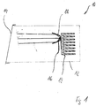
- Figure 1 shows a motor vehicle lighting device 10 with a housing 12, the light exit opening of which is closed by a transparent cover plate 14.
- a light source 16 and a reflector 18 are arranged in the housing 12.
- the light source 16 is designed, for example, as a light-emitting diode (LED).
- the reflector 18 is set up and arranged to bundle the light emanating from the light source 16 and to direct the bundled light directly onto the cover plate 14 or initially onto optical elements, such as a lens or a diaphragm, located in the light path in front of the cover plate 14. so that a legally compliant light distribution is generated in front of the motor vehicle.
- the lighting device 10 is a headlight. In another embodiment, the lighting device 10 is a signal lamp. In a further embodiment, the lighting device 10 has a plurality of light modules, at least one of which fulfills a headlight light function and a further light module a signal light function.
- the light-emitting diodes are arranged on a carrier element.
- the carrier element is, for example, a printed circuit board, a component of a printed circuit board, or a separate part which is mounted on a printed circuit board.
- the circuit board is used in particular for electrical contacting of the light emitting diodes.
- the support element stands directly or over the Printed circuit board in thermal connection with a heat sink 19.
- the heat sink 19 is set up to absorb the heat generated during operation of the LED via the carrier element and, if appropriate, via the printed circuit board and to release it to the environment. It is customary to connect the heat sink 19 to the reflector 18 so that the light source, heat sink and reflector form a unit, which is preassembled, for example, and then integrated into the housing 12 as an assembly.
- the first component 20 is the reflector 18 and the second component 22 is the heat sink 19.
- the invention is not limited to these specific examples of a first component and a second component. Further exemplary embodiments are distinguished by the fact that more other components and / or also more than two components of the lighting device 10 are connected to one another in a non-positive and positive manner by connection structures according to the invention.
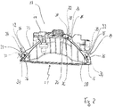
- the Figure 2 shows the reflector 18 in a view which corresponds to a top view from above when used as intended in a motor vehicle.
- the heat sink 19 forming the second component 22 here is shown in FIG Figure 2 largely covered by the reflector 18 and is largely below the plane of the drawing.
- the Combination of the two components 20 and 22 connecting elements 24 For the non-positive and positive connection, the Combination of the two components 20 and 22 connecting elements 24.
- three such connecting elements 24 are distributed over the contour 23 of the combination opposite the light exit side 21.
- Each of the connecting elements 24 consists of a connecting area of the first component 20, a connecting area of the second component 22 and a clamping element 26, which preferably has a U-shaped cross section.
- the connecting element is therefore a structure having the connecting areas of different components and the clamping element.
- the U-shaped clamping element 26 has two flat legs which are connected to one another by a base side 30. Of the two legs is in the Figure 2 to see one leg each as the surface of the clamping element 30.
- the base page 30 appears in the Figure 2 as a corner line.
- the sheet-like legs When pushed on, the sheet-like legs are elastically spread perpendicular to the plane of the drawing, whereby a pair of restoring forces oriented perpendicular to the plane of the drawing is built up for each clamping element.
- the restoring forces of a pair are oriented opposite to each other.
- This pair of restoring forces presses the two components 20 and 22 together.
- the clamping element 26 is therefore set up to apply a force generate, which holds the first component 20 and the second component together by pressing the connection areas of these components against each other in pairs. Strictly speaking, not only is such a force generated, but a pair of forces are generated that hold the first component 20 and the second component together by the forces of this pair pressing the connection areas of these components against each other in pairs.
- the base side 30 of the clamping element has an elongated first recess 32.
- This recess serves to receive a semicircular guide element 28, which is a component of a connection area of the first component 20 and / or the second component 22.
- the semicircular guide element protrudes like a wall or cooling fin from one or both connection areas, its radii being parallel to the plane of the translational assembly movement of the clamping element.
- the wall thickness of the rib preferably corresponds to the width of the elongated recess in the base side 30 of the clamping element.
- the diameter associated with the semicircular shape is greater than the length of the elongated recess in the base side of the clamping element.
- the guide element does not necessarily have to have a semicircular shape. It is sufficient if the guide element has a shape with which, when the clamping element is mounted, it projects through the recess 32 of the clamping element in such a way that edge regions of the part of the guide element protruding therefrom abut on the narrow sides of the recess lying opposite one another and that the part lying between these edge regions and part of the guide element protruding through the recess tapers with increasing distance from the edge regions.
- a guide element which instead of the one in the Figure 2 visible circular shape has an otherwise convexly curved shape, for example a convex free shape or an elliptical shape or also a triangular shape or a trapezoidal shape.
- the clamping element 26 with the first recess 32 is pushed over the guide element 28 so that the guide element 28 projects into the recess 32.
- the shape of the guide element 28 that widens when pushed on means that the position of the clamping element adjusts itself correctly when pushed on, so that the clamping element 26 is correctly positioned in its end position.
- one leg 34 of the clamping element 26 has a second recess 36.
- an engagement element 38 of the first component or of the second component engages in the second recess 36, so that the clamping element 26 is positioned in its end position secured against loss.
- Figure 3 shows an embodiment, in which each leg 34 of the clamping element has a recess 36 and the engaging element 38 bears the reference symbol 38.1 for one leg and bears the reference symbol 38.2 for the other leg.
- Figure 3 shows a connecting element 24 in a first sectional view.
- the associated cutting plane lies in the Figure 2 perpendicular to the plane of the drawing and is in the Figure 2 visible as line BB.
- the U-shaped clamping element 26 has two legs 34.
- the two legs each have a fixed end and a loose end.
- Each leg is connected to the base side 30 with the fixed end, so that the fixed ends are connected to one another via the base side 30.
- the free ends of the legs 34 have insertion geometries 40.
- the insertion geometries 40 are realized, for example, in that the free ends of the legs 34 are curved away from the component on which the leg 34 abuts.
- the legs bend away from one another, in particular at their free ends. This results in a self-adjustment when pushed on, which facilitates the threading of the parts to be connected into the opening of the U-shaped clamping element.
- the curvature is created, for example, by bending the respective free end outwards.
- the first component 20 and the second component 22 are arranged between the legs 34 of the clamping element 26 such that they lie flat against one another at least in regions.
- the first component 20 has a first contact surface 44.1 in its region serving as part of the connecting element 24.
- the second component 22 has in its serving as part of the connecting element 24 Area a first contact surface 44.2. In the assembled state, the two contact surfaces 44.1 and 44.2 abut one another.
- the first component 20 has a second contact surface 42.1 in its area serving as part of the connecting element 24.
- the second contact surface is arranged on the side of the first component opposite the first contact surface and is set up to serve as a contact surface for one of the two legs of the clamping element.
- the second component 20 has a second contact surface 42.2 in its area serving as part of the connecting element 24.
- the second contact surface is arranged on the side of the second component opposite the first contact surface and is set up to serve as a contact surface for the other of the two legs of the clamping element.
- the free ends of the legs 34 taper towards one another in the unmounted state of the clamping element 26. This enables a large amplitude of the spreading and thus a generation of comparatively large restoring forces.
- Figure 4 shows a connecting element 24 in a second sectional view.
- the associated cutting plane lies in the Figure 2 perpendicular to the plane of the drawing and is in the Figure 2 visible as line AA.
- the first component 20 has two engagement elements 38.1 and 38.2. Due to its shape and arrangement, the first engagement element 38.1 is set up to snap into a second recess 36 of the leg 34 which is in direct contact with the first component 20. This is the leg that bears on the second contact surface 42 of the first component 20.
- the second engagement element 38.2 penetrates the second component 22 in order to snap into the second recess 36 of the leg 34 which is in contact with the second component 22. This is the leg that bears on the second contact surface of the second component 22. So that the second engagement element 38.2 can penetrate the second component 22, the second component 22 has a penetration element 46.
- the penetration element 46 is implemented, for example, as a recess in the region of the second component 22 which belongs to a connecting element 24.
- a surface 48 of the engagement element 38 which latches with that of the second recess 36, is preferably designed as an inclined plane.
- the inclined plane is inclined so that the legs 34 are spread when the clamping element 26 is pushed onto the inclined plane. If the surfaces 48 come in the end position of the clamping element 26 in the second recesses 36, they tend live leg 34 to return to its original position. As a result, the engagement elements 38 snap into the second recesses 36.
- the first component 20 and the second component 22 are then also connected to one another in a form-fitting manner, the positive fit acting in one plane being secured by a force fit acting perpendicularly thereto.
- the in the Figures 2 to 4 relate to a reflector as the first component and a heat sink as the second component.
- the first component and / or the second component also represent other elements belonging to the lighting device, such as, for example, screens, covers or design elements.
- the clamping element then counting as the fourth component. It is important to ensure that the components in the connecting elements 24 lie on top of one another in a sandwich-like manner.
- one of the components has the engaging elements 38 and the other two components have the penetration elements 46.
- the component lying in the middle has a depression on a first side and a second one opposite the first side Side has an engagement element.
- the engaging element 38 of the component which lies on the first side of the central component, engages in the depression of the first side.
- the engaging element 38 of the central component engages in a depression which has the component which lies on the second side of the central component.
- the component which is arranged in the middle between the two other components has only second surfaces 44. In particular, this component has no first surfaces 42 on which the legs 34 of the clamping element 26 abut.
- the figures thus show, in particular, a motor vehicle lighting device 10 with at least two components 20, 22 which are connected to one another in a force-locking and positive manner, the two components 20, 22 having contact surfaces 42, 44 which are pressed against one another by a connecting element.
- the lighting device is characterized in that the connecting element is a clamping element 26 having two legs 34, which is designed to grip around the at least two components and thereby generate a force acting perpendicular to the surfaces 42, 44, which force the surfaces 42, 44 presses against one another, and wherein at least one of the two components 20, 22 has an engagement element 38 which, in one end position of the clamping element 26, engages in a second recess 36 which is arranged in a leg 34 of the clamping element 26.
- the clamping element is preferably locked with one of the at least two components.
- the two components are positively connected to one another and also non-positively connected to one another by the clamping element.
Landscapes
- Engineering & Computer Science (AREA)
- General Engineering & Computer Science (AREA)
- Non-Portable Lighting Devices Or Systems Thereof (AREA)
- Clamps And Clips (AREA)
Description
- Die Erfindung betrifft eine Kraftfahrzeugbeleuchtungseinrichtung mit den Merkmalen des Oberbegriffs des Anspruchs 1.
- Eine solche Kraftfahrzeugbeleuchtungseinrichtung ist aus der
WO2013/037799 A1 bekannt. Sie weist mindestens zwei Bauteile auf, die kraftschlüssig und formschlüssig miteinander verbunden sind, wobei die zwei Bauteile Anlageflächen aufweisen, die durch ein Verbindungselement aufeinander gepresst werden. - Die Verbindung der beiden Bauteile erfolgt bei häufig durch Schraubverbindungen. Nachteilig ist dabei der große Platzbedarf, der bei der Montage der Schraubverbindungen für das Bewegen des Werkzeugs erforderlich ist. Außerdem entstehen beim Festziehen der Schraubverbindung Momente und/oder Spannungsspitzen, die zu einem Verziehen oder einer Beschädigung des Verbundes oder der einzelnen Bauteile des Verbundes führen können.
- Die Druckschrift
JP H03 55904 - Vor diesem Hintergrund besteht eine Aufgabe der vorliegenden Erfindung in der Angabe einer Kraftfahrzeugbeleuchtungseinrichtung, deren Bauteile platzsparend und ohne Beschädigungsgefahr montierbar sind.
- Diese Aufgabe wird durch eine Kraftfahrzeugbeleuchtungseinrichtung nach Anspruch 1 gelöst.
- Die Erfindung unterscheidet sich vom Stand der Technik durch die kennzeichnenden Merkmale des Anspruchs 1.
- Das Umgreifen der mindestens zwei Bauteile durch ein zwei Schenkel aufweisendes, insbesondere u-förmiges Klemmelement hat den großen Vorteil, dass das Klemmelement mit einer rein transversalen Montagebewegung montierbar ist, wobei die Bauteile im montierten Zustand kraftschlüssig und formschlüssig verbunden sind. Dabei sind die zu verbindenden Teile bevorzugt sowohl miteinander als auch mit dem Klemmelement verbunden, wobei das Klemmelement bevorzugt mit nur einem der beiden Bauteil verrastet ist.
- Dadurch wird im Gegensatz zur Schraubverbindung, die zusätzlich durch eine rotatorische Bewegung montiert wird, weniger Bauraum benötigt. Außerdem können dadurch die Montagehilfsmittel einfacher und kostengünstiger gestaltet sein. Ein weiterer Vorteil ist es, dass durch die kraftschlüssige Verbindung mittels eines transversal zu montierenden Klemmelements die Gefahr gemindert wird, Momente oder Spannungsspitzen zu erzeugen, die zu einem Verziehen oder einer Beschädigung des Bauteils führen.
- Erfindungsgemäß weist ein erstes der mindestens zwei Bauteile ein Eingriffselement auf, das ein zweites der mindestens zwei Bauteile durchdringt. Somit wird eine platzsparende und sichere formschlüssige Verbindung zwischen dem ersten und dem zweiten Bauteil hergestellt.
- Das Klemmelement ist bevorzugt u-förmig. Die kraftschlüssige Verbindung der Bauteile wird dadurch hergestellt, dass die Bauteile erste Flächen und zweite Flächen aufweisen. Im montierten Zustand liegen die Schenkel des u-förmigen Klemmelements an den ersten Flächen an. Mit den zweiten Flächen liegen die Bauteile aneinander an. Die Schenkel des Klemmelements werden bei der durch Aufbiegen des Klemmelements erfolgender Montage elastisch verformt, so dass in einer Endlage des Klemmelements eine Rückstellkraft senkrecht zu den Flächen wirkt, die die Bauteile zusammen presst.
- Die formschlüssige Verbindung der Bauteile kommt dadurch zustande, dass wenigstens eines der zwei Bauteile ein Eingriffselement aufweist, das in einer Endlage des Klemmelements in eine zweite Ausnehmung in den Schenkeln des Klemmelements einrastet.
- Ergänzend wird vorgeschlagen, dass das zweite Eingriffselement in eine zweite Ausnehmung in den Schenkeln des Klemmelements einrastet. Dies stellt eine einfache Lösung dar, einerseits wenigstens zwei Bauteile formschlüssig zu verbinden und andererseits das Klemmelement beidseitig gegen Verlieren gesichert in seiner Endlage zu halten.
- Es ist bevorzugt, dass eine Oberfläche des ersten Eingriffselements und/oder das zweiten Eingriffselements, die in die zweite Ausnehmung rastet, als schiefe Ebene ausgebildet ist. Das Klemmelement wird auf seinem Weg in die Endlage zunächst mit den beiden Schenkeln über die eine oder über die gegebenenfalls zwei schiefen Ebenen geschoben. Wenn zwei schiefe Ebenen vorhanden sind, so sind diese so angeordnet, dass ihr Abstand in Richtung der Montagebewegung größer wird. Dadurch werden das Klemmelement beim Aufschieben elastisch verformt. Erreicht das Klemmelement die Endlage, liegen die Oberflächen unter den zweiten Ausnehmungen in den Schenkeln. Die Spannung in den elastisch verformten Schenkeln, zieht die Schenkel zurück in Richtung ihrer Ausgangslage, so dass die Oberfläche in den zweiten Ausnehmungen einrastet. Die als schiefe Ebene ausgebildete Oberfläche erleichtert die Montage des Klemmelements und verhindert ein selbständig und unbeabsichtigt erfolgendes Lösen der Klemmverbindung.
- Eine weitere Ausgestaltung sieht vor, dass eine Grundseite des Klemmelements eine erste Ausnehmung aufweist und dass wenigstens eines der mindestens zwei Bauteile ein Führungselement aufweist, das dazu eingerichtet und angeordnet ist, die erste Ausnehmung durch eine bei der Aufschiebebewegung automatisch erfolgende Selbst justierung zu zentrieren und damit das Klemmelement zu positionieren. Das Führungselement ist beispielsweise als halbrundförmige Rippe ausgeformt, und die zweite Ausnehmung ist als Rechteck ausgeführt, dessen Breite der Rippendicke und dessen Länge dem Durchmesser des Halbkreises entsprechen.
- Die Position der zweiten Ausnehmung, die in einem der Schenkel angeordnet ist oder die gegebenenfalls auch in beiden Schenkeln angeordnet sein kann, ist konstruktiv so festgelegt, dass sie in der Endlage des Klemmelements so über einem Eingriffselement liegt, dass dieses in die Ausnehmung einrasten kann. Durch das Führungselement und die erste Ausnehmung gelangt das Klemmelement zwangsweise und selbst justierend in die richtige Endlage, wodurch die Montage vereinfacht wird.
- Es ist bevorzugt, dass das Klemmelement aus Metall gefertigt ist. Ein Klemmelement ist auf einfache Art und Weise durch Stanzen und Biegen aus Metall zu fertigen. Durch die Wahl der Metallart oder der Dicke des verwendeten Blechs, ist die Kraft, die senkrecht zu den Flächen wirkt, beeinflussbar. Bevorzugt ist Federstahl als Material des Klemmelements.
- Weiterhin ist es bevorzugt, dass die Schenkel des Klemmelements an ihren freien Enden spitz aufeinander zulaufen. Bei gegebener Verformung, die beim Aufschieben auftritt, sind die Schenkel in der Endlage umso weniger weit geöffnet, je kleiner der Abstand ihrer Enden voneinander vor dem Aufschieben war. Je weniger weit die Öffnung ist, desto kleiner ist eine resultierende Rückstellkraftkomponente, die der Aufschieberichtung entgegengesetzt ist und die daher potentiell zu einer unerwünschten Selbstlösung der Verbindung führen könnte. Denkbar sind auch andere Geometrien der Schenkel, beispielsweise konkav oder konvex gekrümmte Schenkel, die miteinander eine Engstelle bilden, die über die aneinander liegenden Bauteile geschoben wird, wobei der Abstand der Schenkel an der Engstelle geringfügig kleiner ist, als die Dicke der aufeinanderliegende Bauteile.
- Eine weitere Ausgestaltung sieht vor, dass wenigstens ein Schenkel des Klemmelements an seinem freien Ende eine Einführgeometrie aufweist. Die Einführgeometrie ist beispielsweise so ausgeführt, dass das freie Ende des Schenkels von dem Bauteil weg gekrümmt ist. Dadurch wird ein Verkanten des Klemmelements mit den Bauteilen bei der Montage vermieden und das Klemmelement kann leicht und schnell montiert werden. Außerdem wird die Gefahr einer Beschädigung der Bauteile beim Aufschieben des Klemmelements vermindert.
- Ergänzend wird vorgeschlagen, dass ein drittes Bauteil kraft- und formschlüssig mit den zwei Bauteilen verbunden ist. Die erfindungsgemäße kraft- und formschlüssige Verbindung eignet sich für drei Bauteile, wobei die drei Bauteile Verbindungselemente aufweisen, die sandwichartig aufeinander liegen und von dem Klemmelement wie voranstehend beschrieben zusammengepresst werden. In einer nicht erfindungsgemäßen Ausführung, ist die formschlüssige Verbindung zwischen den drei Bauteilen dadurch gewährleistet, dass das in der Mitte liegende Bauteil auf einer ersten Seite eine Vertiefung und auf einer der ersten Seite gegenüberliegenden zweiten Seite ein Eingriffselement aufweist. In die Vertiefung der ersten Seite greift das Eingriffselement, desjenigen Bauteils, das an der ersten Seite des mittleren Bauteils liegt. Das Eingriffselement des mittleren Bauteils greift in eine Vertiefung, die dasjenige Bauteil aufweist, das an der zweiten Seite des mittleren Bauteils liegt. Auf diese Weise werden drei Bauteile platzsparend und sicher miteinander verbunden. Es versteht sich, dass diejenigen Bauteile die in der sandwichartigen Anordnung der Verbindungselemente außen liegen, die ersten Eingriffselemente aufweisen, an denen die zweiten Ausnehmungen des Klemmelements rasten.
- In einer erfindungsgemäßen Ausführung wird vorgeschlagen, dass eines der drei Bauteile das erste Eingriffselement und ein zweites Eingriffselement oder zwei zweite Eingriffselemente aufweist, wobei die beiden anderen Bauteile jeweils ein Durchdringungselement aufweisen. Die beiden Bauteile, die jeweils ein Durchdringungselement aufweisen, können hier die beiden außen liegenden Bauteile oder ein mittleres und ein außen liegendes Bauteil in der sandwichartigen Anordnung der drei Bauteile sein. Ist das Bauteil, das die Eingriffselemente aufweist, ein außen liegendes Bauteil, verfügt es einerseits über ein erstes Eingriffselement, das in die zweite Ausnehmung des Klemmelements rastet, und andererseits über ein zweites Eingriffselement, das zunächst die beiden anderen Bauteile durchdringt und dann in die zweite Ausnehmung des Klemmelements rastet. Es versteht sich, dass das mittlere Bauteil zwei zweite Eingriffselemente aufweist, die zunächst die Durchdringungselemente der beiden außenliegenden Bauteile durchdringen und dann in die zweiten Ausnehmungen des Klemmelements rasten.
- Es versteht sich, dass die vorstehend genannten und die nachstehend noch zu erläuternden Merkmale nicht nur in der jeweils angegebenen Kombination, sondern auch in anderen Kombinationen oder in Alleinstellung verwendbar sind, ohne den Rahmen der vorliegenden Erfindung zu verlassen.
- Ausführungsbeispiele der Erfindung sind in den Zeichnungen dargestellt und werden in der nachfolgenden Beschreibung näher erläutert. Es zeigen jeweils in schematischer Form:
- Figur 1
- ein Beispiel einer Kraftfahrzeugbeleuchtungseinrichtung als Umfeld der Erfindung;
- Figur 2
- einen Reflektor, der als erstes Bauteilmit einem zweiten Bauteil in Form eines Kühlkörpers verbunden ist;
- Figur 3
- ein Verbindungselement aus der
Figur 2 in einer ersten Schnittdarstellung; und - Figur 4
- das Verbindungselement aus der
Figur 2 in einer zweiten Schnittdarstellung; -
Figur 1 zeigt eine Kraftfahrzeugbeleuchtungseinrichtung 10 mit einem Gehäuse 12, dessen Lichtaustrittsöffnung durch eine transparente Abdeckscheibe 14 verschlossen ist. In dem Gehäuse 12 sind eine Lichtquelle 16 und ein Reflektor 18 angeordnet. Die Lichtquelle 16 ist beispielsweise als Licht emittierende Diode (LED) ausgeführt. Der Reflektor 18 ist dazu eingerichtet und angeordnet, das von der Lichtquelle 16 ausgehende Licht zu bündeln und das gebündelte Licht direkt auf die Abdeckscheibe 14 oder zunächst auf im Lichtweg vor der Abdeckscheibe 14 liegende optische Elemente, wie eine Linse oder eine Blende, zu richten, so dass in einem Vorfeld des Kraftfahrzeugs eine gesetzeskonforme Lichtverteilung erzeugt wird. - Die Beleuchtungseinrichtung 10 ist in einer Ausgestaltung ein Scheinwerfer. In einer anderen Ausgestaltung ist die Beleuchtungseinrichtung 10 eine Signalleuchte. In einer weiteren Ausgestaltung weist die Beleuchtungseinrichtung 10 mehrere Lichtmodule auf, von denen wenigsten eines eine Scheinwerferlichtfunktion und ein weiteres Lichtmodul eine Signallichtfunktion erfüllt.
- In der Regel sind die Licht emittierenden Dioden auf einem Trägerelement angeordnet. Das Trägerelement ist zum Beispiel eine Leiterplatte, ein Bestandteil einer Leiterplatte, oder ein separates Teil, das auf eine Leiterplatte montiert ist. Die Leiterplatte dient insbesondere zur elektrischen Kontaktierung der Leuchtdioden. Das Trägerelement steht direkt oder über die Leiterplatte in thermischer Verbindung mit einem Kühlkörper 19. Der Kühlkörper 19 ist dazu eingerichtet, die im Betrieb der LED entstehende Wärme über das Trägerelement und gegebenenfalls über die Leiterplatte aufzunehmen und an die Umgebung abzugeben. Es ist üblich, den Kühlkörper 19 mit dem Reflektor 18 zu verbinden, so dass Lichtquelle, Kühlkörper und Reflektor eine Einheit bilden, die beispielsweise vormontiert wird und anschließend als Baugruppe in das Gehäuse 12 eingebaut integriert wird.
- Anhand der in der
Figur 2 dargestellten Ausgestaltung wird eine kraft- und formschlüssige Verbindung von zwei Bauteilen der Beleuchtungseinrichtung 10 erläutert. In dem dargestellten Ausführungsbeispiel ist das erste Bauteil 20 der Reflektor 18, und das zweite Bauteil 22 ist der Kühlkörper 19. Die Erfindung ist aber nicht auf diese speziellen Beispiele eines ersten Bauteils und eines zweiten Bauteils beschränkt. Weitere Ausführungsbeispiele zeichnen sich dadurch aus, dass mehr andere Bauteile und/oder auch mehr als zwei Bauteile der Beleuchtungseinrichtung 10 durch erfindungsgemäße Verbindungsstrukturen kraft- und formschlüssig miteinander verbunden sind. - Die
Figur 2 zeigt den Reflektor 18 in einer Ansicht, die bei einer bestimmungsgemäßen Verwendung in einem Kraftfahrzeug einer Draufsicht von oben entspricht. Eine Lichtaustrittsseite 21 des Reflektors 18, der sich im Kraftfahrzeug in der Regel in Fahrtrichtung öffnet, weist in derFigur 2 zum unteren Blattrand. Der hier das zweite Bauteil 22 bildende Kühlkörper 19 ist in derFigur 2 weitgehend durch den Reflektor 18 verdeckt und liegt größtenteils unterhalb der Zeichnungsebene. - Für die kraft- und formschlüssige Verbindung weist die Kombination der beiden Bauteile 20 und 22 Verbindungselemente 24 auf. Im gezeigten Ausführungsbeispiel sind drei solche Verbindungselemente 24 über die der Lichtaustrittseite 21 gegenüberliegende Kontur 23 der Kombination verteilt angeordnet. Jedes der Verbindungselemente 24 besteht aus einem Verbindungsbereich des ersten Bauteils 20, einem Verbindungsbereich des zweiten Bauteils 22 und einem Klemmelement 26, das bevorzugt einen u-förmigen Querschnitt aufweist. Das Verbindungselement ist daher eine die Verbindungsbereiche verschiedener Bauteile und das Klemmelement aufweisende Struktur.
- Das u-förmige Klemmelement 26 weist zwei flächige Schenkel auf, die durch eine Grundseite 30 miteinander verbunden sind. Von den zwei Schenkeln ist in der
Figur 2 jeweils ein Schenkel als Fläche des Klemmelements 30 zu sehen. Die Grundseite 30 erscheint in derFigur 2 als eine Ecken aufweisende Linie. Bei der Montage des Klemmelements wird das Klemmelement translatorisch auf die zunächst nur lose zusammengefügten Bauteile 20 und 22 aufgeschoben. Die beiden Bauteile liegen dabei zum Beispiel mit Anlageflächen aneinander an, die parallel zur Zeichnungsebene derFigur 2 liegen. Die translatorische Bewegung erfolgt in dem dargestellten Ausführungsbeispiel längs einer Richtung, die etwa parallel zu der in derFigur 2 von links oben nach rechts unten verlaufenden Blattdiagonalen ist. Beim Aufschieben werden die flächenförmigen Schenkel senkrecht zur Zeichnungsebene elastisch gespreizt, wodurch pro Klemmelement ein Paar von senkrecht zur Zeichnungsebene ausgerichteten Rückstellkräften aufgebaut wird. Die Rückstellkräfte eines Paars sind dabei entgegengesetzt zueinander ausgerichtet. Dieses Paar von Rückstellkräften presst die beiden Bauelemente 20 und 22 zusammen. Das Klemmelement 26 ist daher dazu eingerichtet, eine Kraft zu erzeugen, die das erste Bauteil 20 und das zweite Bauteil zusammenhält, indem es die Verbindungsbereiche dieser Bauteile jeweils paarweise gegeneinander presst. Genau genommen wird dabei nicht nur eine solche Kraft erzeugt, sondern es wird ein Paar von Kräften erzeugt, die das erste Bauteil 20 und das zweite Bauteil zusammenhalten, indem die Kräfte dieses Paars die Verbindungsbereiche dieser Bauteile jeweils paarweise gegeneinander pressen. - Die genaue Funktionsweise der Verbindungselemente 24 wird weiter unten anhand der nachfolgenden
Figuren 3 und 4 noch näher erläutert. - Die Grundseite 30 des Klemmelements weist eine längliche erste Ausnehmung 32 auf. Diese Ausnehmung dient zur Aufnahme eines halbkreisförmigen Führungselements 28, welches ein Bestandteil eines Verbindungbereiches des ersten Bauteils 20 und/oder des zweiten Bauteils 22 ist. Das hier halbrunde Führungselement steht wie eine Wand oder Kühlrippe von einem oder beiden Verbindungsbereichen ab, wobei seine Radien parallel zu der Ebene der translatorischen Montagebewegung des Klemmelements liegen.
- Die Wandstärke der Rippe entspricht bevorzugt der Breite der länglichen Ausnehmung in der Grundseite 30 des Klemmelements. Der zur Halbrundform zugehörige Durchmesser ist größer als die Länge der länglichen Ausnehmung in der Grundseite des Klemmelements. Dadurch lässt sich das Klemmelement gerade soweit aufschieben, bis die beiden Schmalseiten der länglichen Ausnehmung an die Halbrundform anstoßen. Dadurch wird die Position des Klemmelements im montierten Zustand festgelegt. Die Ausnehmung in der Grundseite 30 des Klemmelements bewirkt daher im Zusammenwirken mit dem halbkreisförmigen Führungselement eine bei der translatorischen Aufschiebebewegung automatisch erfolgende Zentrierung und damit Selbst justierung der Lage des Klemmelements im montierten Zustand.
- Das Führungselement muss nicht notwendig eine Halbkreisform besitzen. Es genügt, wenn das Führungselement eine Form besitzt, mit der es bei montiertem Klemmelement durch die Ausnehmung 32 des Klemmelements so hindurch ragt, dass Randbereiche des hindurch ragenden Teils des Führungselements an den einander gegenüberliegenden Schmalseiten der Ausnehmung anliegen und dass der zwischen diesen Randbereichen liegende und durch die Ausnehmung hindurch ragende Teil des Führungselements sich mit zunehmendem Abstand von den Randbereichen verjüngt. Dies würde zum Beispiel auch durch ein Führungselement erfüllt, das an Stelle der in der
Figur 2 sichtbaren Kreisform eine anderweitig konvex gekrümmte Form, zum Beispiel eine konvexe Freiform oder eine elliptische Form oder auch eine Dreiecksform oder eine Trapezform aufweist. - Bei der Montage wird das Klemmelement 26 mit der ersten Ausnehmung 32 über das Führungselement 28 geschoben so dass das Führungselement 28 in die Ausnehmung 32 hineinragt. Die sich beim Aufschieben erweiternde Form des Führungselements 28 führt dazu, dass sich die Lage des Klemmelements beim Aufschieben selbst justierend richtig einstellt, so dass das Klemmelement 26 richtig in seiner Endlage positioniert ist.
- Weiter ist aus der
Figur 2 ersichtlich, dass ein Schenkel 34 des Klemmelements 26 eine zweite Ausnehmung 36 aufweist. Beim Aufschieben des Klemmelements 26 in seine Endlage rastet ein Eingriffselement 38 des ersten Bauteils oder des zweiten Bauteils in die zweite Ausnehmung 36 ein, so dass das Klemmelement 26 gegen Verlieren gesichert in seiner Endlage positioniert ist.Figur 3 zeigt eine Ausgestaltung, bei der jeder Schenkel 34 des Klemmelements eine Ausnehmung 36 aufweist und das Eingriffselement 38 für den einen Schenkel das Bezugszeichen 38.1 trägt und für den anderen Schenkel das Bezugszeichen 38.2 trägt. -
Figur 3 zeigt ein Verbindungselement 24 in einer ersten Schnittdarstellung. Die zugehörige Schnittebene liegt in derFigur 2 senkrecht zur Zeichnungsebene und ist in derFigur 2 als Linie B-B sichtbar. - Das u-förmige Klemmelement 26 weist zwei Schenkel 34 auf. Die beiden Schenkel weisen jeweils ein festes Ende und ein loses Ende auf. Mit dem festen Ende ist jeder Schenkel mit der Grundseite 30 verbunden, so dass die festen Enden über die Grundseite 30 miteinander verbunden sind. Die freien Enden der Schenkel 34 weisen Einführgeometrien 40 auf. Die Einführgeometrien 40 sind beispielsweise dadurch realisiert, dass die freien Enden der Schenkel 34 von demjenigen Bauteil weg gekrümmt sind, an dem der Schenkel 34 anliegt. Die Schenkel krümmen sich damit insbesondere an ihren freien Enden voneinander weg. Dadurch wird beim Aufschieben eine Selbst justierung erzielt, welche das Einfädeln der zu verbindenden Teile in die Öffnung des u-förmigen Klemmelements erleichtert. Die Krümmung wird zum Beispiel durch Umbiegen des jeweiligen freien Endes nach außen erzeugt.
- Zwischen den Schenkeln 34 des Klemmelements 26 sind das erste Bauteil 20 und das zweite Bauteil 22 so angeordnet, dass sie zumindest bereichsweise flächig aneinander liegen.
- Das erste Bauteil 20 weist in seinem als Teil des Verbindungselementes 24 dienenden Bereich eine erste Anlagefläche 44.1 auf. Das zweite Bauteil 22 weist in seinem als Teil des Verbindungselementes 24 dienenden Bereich eine erste Anlagefläche 44.2 auf. Im zusammengefügten Zustand liegen die beiden Anlageflächen 44.1 und 44.2 aneinander an.
Das erste Bauteil 20 weist in seinem als Teil des Verbindungselementes 24 dienenden Bereich eine zweite Anlagefläche 42.1 auf. Die zweite Anlagefläche ist auf der der ersten Anlagefläche gegenüberliegenden Seite des ersten Bauteils angeordnet und dazu eingerichtet, als Anlagefläche für den einen der beiden Schenkel des Klemmelements zu dienen. - Das zweite Bauteil 20 weist in seinem als Teil des Verbindungselements 24 dienenden Bereich eine zweite Anlagefläche 42.2 auf. Die zweite Anlagefläche ist auf der der ersten Anlagefläche gegenüber liegenden Seite des zweiten Bauteils angeordnet und dazu eingerichtet, als Anlagefläche für den anderen der beiden Schenkel des Klemmelements zu dienen. Im zusammengefügten Zustand der beiden Bauteile 20 und 22 ist der Abstand der beiden zweiten Anlageflächen voneinander so groß, dass die beiden Schenkel des u-förmigen Klemmelements beim Aufschieben gespreizt werden, was letztlich das auf die beiden ersten Anlageflächen wirkende und diese zusammenpressende Kräftepaar erzeugt. Die beiden Bauteile 20 und 21 sind somit kraftschlüssig miteinander verbunden.
- Es ist bevorzugt, dass die freien Enden der Schenkel 34 im nichtmontierten Zustand des Klemmelements 26 spitz aufeinander zulaufen. Dies ermöglicht eine große Amplitude der Aufspreizung und damit eine Erzeugung vergleichsweise großer Rückstellkräfte.
-
Figur 4 zeigt ein Verbindungselement 24 in einer zweiten Schnittdarstellung. Die zugehörige Schnittebene liegt in derFigur 2 senkrecht zur Zeichnungsebene und ist in derFigur 2 als Linie A-A sichtbar. - In der dargestellten Ausgestaltung ist das im Zusammenhang mit der
Figur 2 erläuterte Führungselement 28 ein Bestandteil des zweiten Bauteils. Das Führungselement ragt durch die erste Ausnehmung 32, die in der Grundseite 30 des Klemmelements 26 angeordnet ist, hindurch. - In der
Figur 4 weist das erste Bauteil 20 zwei Eingriffselemente 38.1 und 38.2 auf. Das erste Eingriffselement 38.1 ist durch seine Form und Anordnung dazu eingerichtet, in eine zweite Ausnehmung 36 desjenigen Schenkels 34 einzurasten, der direkt mit dem ersten Bauteil 20 in Kontakt steht. Dies ist der Schenkel, der an der zweiten Anlagefläche 42 des ersten Bauteils 20 anliegt. Das zweite Eingriffselement 38.2 durchdringt in der dargestellten Ausgestaltung das zweite Bauteil 22, um in die zweite Ausnehmung 36 desjenigen Schenkels 34 einzurasten, der mit dem zweiten Bauteil 22 in Kontakt steht. Dies ist der Schenkel, der an der zweiten Anlagefläche des zweiten Bauteils 22 anliegt. Damit das zweite Eingriffselement 38.2 das zweite Bauteil 22 durchdringen kann, weist das zweite Bauteil 22 ein Durchdringungselement 46 auf. Das Durchdringungselement 46 ist beispielsweise als Ausnehmung in dem Bereich des zweiten Bauteils 22 realisiert, der zu einem Verbindungselement 24 gehört. - Eine Oberfläche 48 des Eingriffselements 38, das mit der der zweiten Ausnehmung 36 verrastet, ist bevorzugt als schiefe Ebene ausgebildet. Die schiefe Ebene ist so geneigt, dass die Schenkel 34 beim Aufschieben des Klemmelements 26 auf die schiefe Ebene gespreizt werden. Kommen die Oberflächen 48 in der Endlage des Klemmelements 26 in den zweiten Ausnehmungen 36 liegen, tendieren die unter Spannung stehenden Schenkel 34 dazu, in ihre Ausgangslage zurück zukehren. Folglich rasten die Eingriffselemente 38 in die zweiten Ausnehmungen 36 ein. Das erste Bauteil 20 und das zweite Bauteil 22 sind dann auch formschlüssig miteinander verbunden, wobei der in einer Ebene wirkende Formschluss durch einen senkrecht dazu wirkenden Kraftschluss gesichert ist.
- Die in den
Figuren 2 bis 4 beschriebenen Ausführungsbeispiele beziehen sich auf einen Reflektor als erstes Bauteil und einen Kühlkörper als zweites Bauteil. Alternativ oder ergänzend ist vorgesehen, dass das erste Bauteil und/oder das zweite Bauteil auch andere zu der Beleuchtungseinrichtung gehörende Elemente darstellen, wie beispielsweise Blenden, Abdeckungen oder Designelemente. - Weitere Anwendungsbeispiele sehen vor, dass drei Bauteile miteinander verbunden sind, wobei das Klemmelement dann als viertes Bauteil zählen würde. Dabei ist darauf zu achten, dass die Bauteile in den Verbindungselementen 24 sandwichartig aufeinander liegen. Zu Herstellung einer formschlüssigen Verbindung weist eines der Bauteile die Eingriffselemente 38 auf und die beiden anderen Bauteile verfügen über die Durchdringungselemente 46. Eine Ausgestaltung sieht vor, dass das in der Mitte liegende Bauteil auf einer ersten Seite eine Vertiefung und auf einer der ersten Seite gegenüberliegenden zweiten Seite ein Eingriffselement aufweist. In die Vertiefung der ersten Seite greift das Eingriffselement 38 des Bauteils, das an der ersten Seite des mittleren Bauteils liegt. Das Eingriffselement 38 des mittleren Bauteils greift in eine Vertiefung, die das Bauteil aufweist, das an der zweiten Seite des mittleren Bauteils liegt. Es versteht sich, dass das Bauteil, das in der Mitte zwischen den beiden anderen Bauteilen angeordnet ist, nur zweite Flächen 44 aufweist. Dieses Bauteil weist insbesondere keine ersten Flächen 42 auf, an denen die Schenkel 34 des Klemmelements 26 anliegen.
- Insgesamt zeigen die Figuren damit insbesondere ein Kraftfahrzeugbeleuchtungseinrichtung 10 mit mindestens zwei Bauteilen 20, 22, die kraftschlüssig und formschlüssig miteinander verbunden sind, wobei die zwei Bauteile 20, 22 Anlageflächen 42, 44 aufweisen, die durch ein Verbindungselement aufeinander gepresst werden. Die Beleuchtungseinrichtung zeichnet sich dadurch aus, dass das Verbindungselement ein zwei Schenkel 34 aufweisendes Klemmelement 26 ist, das dazu eingerichtet ist, die mindestens zwei Bauteile zu umgreifen und dabei eine senkrecht zu den Flächen 42,44 wirkende Kraft zu erzeugen, welche die Flächen 42, 44 aufeinander presst, und wobei wenigstens eines der zwei Bauteile 20, 22 ein Eingriffselement 38 aufweist, das in einer Endlage des Klemmelements 26 in eine zweite Ausnehmung 36 einrastet, die in einem Schenkel 34 des Klemmelements 26 angeordnet ist.
- Das Klemmelement ist dabei bevorzugt mit einem der wenigstens zwei Bauteile verrastet. Die beiden Bauteile sind untereinander formschlüssig und durch das Klemmelement auch kraftschlüssig miteinander verbunden.
Claims (11)
- Kraftfahrzeugbeleuchtungseinrichtung (10) mit mindestens zwei Bauteilen (20, 22), die kraftschlüssig und formschlüssig miteinander verbunden sind, wobei die zwei Bauteile (20, 22) Anlageflächen (44.1, 44.2) aufweisen, die durch ein Verbindungselement aufeinander gepresst werden, wobei das Verbindungselement ein zwei Schenkel (34) aufweisendes Klemmelement (26) ist, das dazu eingerichtet ist, die mindestens zwei Bauteile zu umgreifen und dabei eine senkrecht zu den Anlageflächen wirkende Kraft zu erzeugen, welche die Anlageflächen aufeinander presst, und wobei wenigstens eines der zwei Bauteile (20, 22) ein Eingriffselement (38.2) aufweist, das in einer Endlage des Klemmelements (26) in eine Ausnehmung (36) einrastet, die in einem Schenkel (34)' des Klemmelements (26) angeordnet ist, dadurch gekennzeichnet, dass das Eingriffselement (38.2) eines der mindestens zwei Bauteile (20, 22) das andere der mindestens zwei Bauteile (20, 22) durchdringt.
- Kraftfahrzeugbeleuchtungseinrichtung (10) nach vorangehendem Anspruch 1, dadurch gekennzeichnet, dass das Klemmelement (26) eine Grundseite (30) aufweist, von der die beiden Schenkel (34) u-förmig weg streben.
- Kraftfahrzeugbeleuchtungseinrichtung (10) nach Anspruch 2, dadurch gekennzeichnet, dass die Grundseite (30) des Klemmelements (26) eine erste Ausnehmung (32) aufweist und dass wenigstens eines der mindestens zwei Bauteile (20, 22) ein Führungselement (28) aufweist, das dazu eingerichtet und angeordnet ist, die erste Ausnehmung (32) zu zentrieren und damit das Klemmelement (26) zu positionieren.
- Kraftfahrzeugbeleuchtungseinrichtung (10) nach einem der vorangehenden Ansprüche, dadurch gekennzeichnet, dass das Eingriffselement (38.2) mit der Ausnehmung (36) verrastet ist, die in den Schenkeln (34) des Klemmelements (26) angeordnet ist.
- Kraftfahrzeugbeleuchtungseinrichtung (10) nach einem der vorangehenden Ansprüche, dadurch gekennzeichnet, dass eine Oberfläche (48) des Eingriffselements (38.2), die in die zweite Ausnehmung (36) einrastet, als schiefe Ebene ausgebildet ist.
- Kraftfahrzeugbeleuchtungseinrichtung (10) nach einem der vorangehenden Ansprüche, dadurch gekennzeichnet, dass das Klemmelement (26) aus Metall gefertigt ist.
- Kraftfahrzeugbeleuchtungseinrichtung (10) nach Anspruch 6, dadurch gekennzeichnet, dass das Klemmelement (26) aus Federstahl gefertigt ist.
- Kraftfahrzeugbeleuchtungseinrichtung (10) nach einem der vorangehenden Ansprüche, dadurch gekennzeichnet, dass die Schenkel (34) des Klemmelements (26) an ihren freien Enden spitz aufeinander zu laufen.
- Kraftfahrzeugbeleuchtungseinrichtung (10) nach einem der vorangehenden Ansprüche, dadurch gekennzeichnet, dass mindestens ein Schenkel (34) des Klemmelements (26) an seinem freien Ende eine Einführgeometrie (40) aufweist.
- Kraftfahrzeugbeleuchtungseinrichtung (10) nach einem der vorangehenden Ansprüche, dadurch gekennzeichnet, dass ein drittes Bauteil kraft- und formschlüssig mit den zwei Bauteilen (20, 22) verbunden ist.
- Kraftfahrzeugbeleuchtungseinrichtung (10) nach Anspruch 10, dadurch gekennzeichnet, dass eines der drei Bauteile ein Eingriffselement (38.2) oder zwei Eingriffselemente (38.2) aufweist, wobei die beiden anderen Bauteile jeweils ein Durchdringungselement (46) aufweisen und wobei das Durchdringungselement dazu eingerichtet ist, von dem Eingriffselement durchdrungen zu werden.
Applications Claiming Priority (1)
| Application Number | Priority Date | Filing Date | Title |
|---|---|---|---|
| DE201320009156 DE202013009156U1 (de) | 2013-10-16 | 2013-10-16 | Kraftfahrzeugbeleuchtungseinrichtung |
Publications (2)
| Publication Number | Publication Date |
|---|---|
| EP2863109A1 EP2863109A1 (de) | 2015-04-22 |
| EP2863109B1 true EP2863109B1 (de) | 2020-05-20 |
Family
ID=51570322
Family Applications (1)
| Application Number | Title | Priority Date | Filing Date |
|---|---|---|---|
| EP14185248.3A Active EP2863109B1 (de) | 2013-10-16 | 2014-09-18 | Kraftfahrzeugbeleuchtungseinrichtung |
Country Status (3)
| Country | Link |
|---|---|
| EP (1) | EP2863109B1 (de) |
| CN (1) | CN104553958B (de) |
| DE (1) | DE202013009156U1 (de) |
Families Citing this family (2)
| Publication number | Priority date | Publication date | Assignee | Title |
|---|---|---|---|---|
| CN108613071A (zh) * | 2018-07-05 | 2018-10-02 | 张建明 | 一种新型卡扣投光灯 |
| US11047411B2 (en) * | 2019-02-06 | 2021-06-29 | Pro Moto Billet, Inc. | Clamping mirror light |
Family Cites Families (13)
| Publication number | Priority date | Publication date | Assignee | Title |
|---|---|---|---|---|
| DE1201617B (de) * | 1961-06-23 | 1965-09-23 | Raymond Druckknopf Und Metallw | Klammer fuer die Befestigung von Abdeckleisten |
| FR2454049A1 (fr) * | 1978-06-26 | 1980-11-07 | Cibie Projecteurs | Projecteur muni d'agrafes d'assemblage et son procede de fabrication |
| JPH0355904U (de) * | 1989-10-03 | 1991-05-29 | ||
| JP2757934B2 (ja) * | 1993-12-28 | 1998-05-25 | 株式会社小糸製作所 | 自動車用ヘッドランプのエイミング機構 |
| JP3272538B2 (ja) * | 1994-04-15 | 2002-04-08 | 本田技研工業株式会社 | 車両のテールランプ装置 |
| JPH11310076A (ja) * | 1998-04-30 | 1999-11-09 | Koito Mfg Co Ltd | 車輌用灯具 |
| DE19830668C1 (de) * | 1998-07-09 | 2000-04-06 | Daimler Chrysler Ag | Anordnung zum Zusammenfügen von flächigen Bauteilen, insbesondere Außenhautteilen eines Kraftfahrzeuges |
| JP3920052B2 (ja) * | 2001-07-06 | 2007-05-30 | 株式会社小糸製作所 | 自動車用赤外光照射ランプ |
| JP5140403B2 (ja) * | 2007-12-10 | 2013-02-06 | 株式会社小糸製作所 | 車両用前照灯 |
| EP2131101A1 (de) * | 2008-06-02 | 2009-12-09 | odelo GmbH | Leuchte |
| FR2951117B1 (fr) * | 2009-10-12 | 2012-02-03 | Valeo Vision | Dispositif de reglage d'un dispositif d'eclairage et / ou de signalisation d'un vehicule automobile et procede de montage d'un tel dispositif |
| WO2012095758A2 (en) * | 2011-01-11 | 2012-07-19 | Koninklijke Philips Electronics N.V. | Lighting device |
| FR2982006B1 (fr) * | 2011-09-13 | 2018-04-27 | Valeo Vision | Module optique a reference commune, pour eclairage et/ou signalisation d'un vehicule automobile |
-
2013
- 2013-10-16 DE DE201320009156 patent/DE202013009156U1/de not_active Expired - Lifetime
-
2014
- 2014-09-18 EP EP14185248.3A patent/EP2863109B1/de active Active
- 2014-10-16 CN CN201410546702.XA patent/CN104553958B/zh active Active
Non-Patent Citations (1)
| Title |
|---|
| None * |
Also Published As
| Publication number | Publication date |
|---|---|
| CN104553958B (zh) | 2018-10-19 |
| CN104553958A (zh) | 2015-04-29 |
| EP2863109A1 (de) | 2015-04-22 |
| DE202013009156U1 (de) | 2015-01-19 |
Similar Documents
| Publication | Publication Date | Title |
|---|---|---|
| DE102008010026A1 (de) | Elektrische Anschluss- und Verbindungsdose für ein Solarzellenmodul | |
| DE112016002760T5 (de) | Klemme und Klemmenanordnung | |
| DE102012206731A1 (de) | Anschlussvorrichtung für ein Solarmodul | |
| DE202014100486U1 (de) | Deformierbares befestigungselement und wechselrichter | |
| AT12910U1 (de) | Vorrichtung zum befestigen und kontaktieren eines leuchtmittels und/oder eines leuchtmoduls, sowie leuchte | |
| EP2705297A1 (de) | Leuchteinheit für fahrzeuge | |
| DE102013214755A1 (de) | Elektrisches Speicherelement und Verfahren zu seiner Herstellung | |
| DE102016004336A1 (de) | Clip zum Befestigen eines Elements an einem anderen Element und Verwendung eines solchen zweiteiligen Clips | |
| DE102007038788B4 (de) | Leuchtmodul für eine Halbleiterlichtquellen-Leuchte und Halbleiterlichtquellen-Leuchte | |
| DE69308797T2 (de) | Geräteträger anzubringen auf einen Kabelkanal mit einander gegenüberliegenden Vorsprüngen | |
| DE102007050985A1 (de) | Befestigungsklammer | |
| EP3608588B1 (de) | Haltefeder für leuchte | |
| AT517417B1 (de) | Beleuchtungsvorrichtung für einen Kraftfahrzeugscheinwerfer | |
| DE102008060282B4 (de) | Werkzeuglos betätigbare Federklemme für elektrische Leiter | |
| DE202016101365U1 (de) | Klemme | |
| EP2863109A1 (de) | Kraftfahrzeugbeleuchtungseinrichtung | |
| DE102010008354A1 (de) | Elektrische Anschlussklemme | |
| DE102014105686B3 (de) | Elektrisches Kontaktteil und Verfahren zum Verbinden des Kontaktteils | |
| EP2568215B1 (de) | Lichtbandleuchte | |
| AT16079U1 (de) | Befestigungselement zur Verbindung zwischen einer LED-Platine und einem Leuchten-Bauteil | |
| DE102011085650B4 (de) | Befestigung eines Steuergerätes für ein Getriebesteuermodul an einer Trägerplatte | |
| DE202012103987U1 (de) | Anschlussvorrichtung zum Anschließen eines abisolierten elektrischen Leiters und elektrische Anschlussklemme | |
| DE102014203768A1 (de) | Elektrischer Anschlußkasten | |
| EP3499563A1 (de) | Leistungshalbleitermodul und verfahren zur kraftschlüssigen anordnung eines leistungshalbleitermoduls | |
| DE102008049852A1 (de) | Vorrichtung zur elektrischen Verbindung von Zellableitern |
Legal Events
| Date | Code | Title | Description |
|---|---|---|---|
| PUAI | Public reference made under article 153(3) epc to a published international application that has entered the european phase |
Free format text: ORIGINAL CODE: 0009012 |
|
| 17P | Request for examination filed |
Effective date: 20140918 |
|
| AK | Designated contracting states |
Kind code of ref document: A1 Designated state(s): AL AT BE BG CH CY CZ DE DK EE ES FI FR GB GR HR HU IE IS IT LI LT LU LV MC MK MT NL NO PL PT RO RS SE SI SK SM TR |
|
| AX | Request for extension of the european patent |
Extension state: BA ME |
|
| R17P | Request for examination filed (corrected) |
Effective date: 20151021 |
|
| RBV | Designated contracting states (corrected) |
Designated state(s): AL AT BE BG CH CY CZ DE DK EE ES FI FR GB GR HR HU IE IS IT LI LT LU LV MC MK MT NL NO PL PT RO RS SE SI SK SM TR |
|
| REG | Reference to a national code |
Ref country code: DE Ref legal event code: R079 Ref document number: 502014014201 Country of ref document: DE Free format text: PREVIOUS MAIN CLASS: F21S0008100000 Ipc: F21S0041390000 |
|
| GRAP | Despatch of communication of intention to grant a patent |
Free format text: ORIGINAL CODE: EPIDOSNIGR1 |
|
| STAA | Information on the status of an ep patent application or granted ep patent |
Free format text: STATUS: GRANT OF PATENT IS INTENDED |
|
| RIC1 | Information provided on ipc code assigned before grant |
Ipc: F16B 5/06 20060101ALI20191107BHEP Ipc: F21S 45/49 20180101ALI20191107BHEP Ipc: F21V 17/16 20060101ALI20191107BHEP Ipc: F21S 41/39 20180101AFI20191107BHEP |
|
| INTG | Intention to grant announced |
Effective date: 20191205 |
|
| GRAS | Grant fee paid |
Free format text: ORIGINAL CODE: EPIDOSNIGR3 |
|
| GRAA | (expected) grant |
Free format text: ORIGINAL CODE: 0009210 |
|
| STAA | Information on the status of an ep patent application or granted ep patent |
Free format text: STATUS: THE PATENT HAS BEEN GRANTED |
|
| AK | Designated contracting states |
Kind code of ref document: B1 Designated state(s): AL AT BE BG CH CY CZ DE DK EE ES FI FR GB GR HR HU IE IS IT LI LT LU LV MC MK MT NL NO PL PT RO RS SE SI SK SM TR |
|
| REG | Reference to a national code |
Ref country code: GB Ref legal event code: FG4D Free format text: NOT ENGLISH |
|
| REG | Reference to a national code |
Ref country code: CH Ref legal event code: EP |
|
| REG | Reference to a national code |
Ref country code: DE Ref legal event code: R096 Ref document number: 502014014201 Country of ref document: DE |
|
| REG | Reference to a national code |
Ref country code: AT Ref legal event code: REF Ref document number: 1272832 Country of ref document: AT Kind code of ref document: T Effective date: 20200615 |
|
| REG | Reference to a national code |
Ref country code: LT Ref legal event code: MG4D |
|
| REG | Reference to a national code |
Ref country code: NL Ref legal event code: MP Effective date: 20200520 |
|
| PG25 | Lapsed in a contracting state [announced via postgrant information from national office to epo] |
Ref country code: PT Free format text: LAPSE BECAUSE OF FAILURE TO SUBMIT A TRANSLATION OF THE DESCRIPTION OR TO PAY THE FEE WITHIN THE PRESCRIBED TIME-LIMIT Effective date: 20200921 Ref country code: IS Free format text: LAPSE BECAUSE OF FAILURE TO SUBMIT A TRANSLATION OF THE DESCRIPTION OR TO PAY THE FEE WITHIN THE PRESCRIBED TIME-LIMIT Effective date: 20200920 Ref country code: SE Free format text: LAPSE BECAUSE OF FAILURE TO SUBMIT A TRANSLATION OF THE DESCRIPTION OR TO PAY THE FEE WITHIN THE PRESCRIBED TIME-LIMIT Effective date: 20200520 Ref country code: GR Free format text: LAPSE BECAUSE OF FAILURE TO SUBMIT A TRANSLATION OF THE DESCRIPTION OR TO PAY THE FEE WITHIN THE PRESCRIBED TIME-LIMIT Effective date: 20200821 Ref country code: FI Free format text: LAPSE BECAUSE OF FAILURE TO SUBMIT A TRANSLATION OF THE DESCRIPTION OR TO PAY THE FEE WITHIN THE PRESCRIBED TIME-LIMIT Effective date: 20200520 Ref country code: NO Free format text: LAPSE BECAUSE OF FAILURE TO SUBMIT A TRANSLATION OF THE DESCRIPTION OR TO PAY THE FEE WITHIN THE PRESCRIBED TIME-LIMIT Effective date: 20200820 Ref country code: LT Free format text: LAPSE BECAUSE OF FAILURE TO SUBMIT A TRANSLATION OF THE DESCRIPTION OR TO PAY THE FEE WITHIN THE PRESCRIBED TIME-LIMIT Effective date: 20200520 |
|
| PG25 | Lapsed in a contracting state [announced via postgrant information from national office to epo] |
Ref country code: BG Free format text: LAPSE BECAUSE OF FAILURE TO SUBMIT A TRANSLATION OF THE DESCRIPTION OR TO PAY THE FEE WITHIN THE PRESCRIBED TIME-LIMIT Effective date: 20200820 Ref country code: HR Free format text: LAPSE BECAUSE OF FAILURE TO SUBMIT A TRANSLATION OF THE DESCRIPTION OR TO PAY THE FEE WITHIN THE PRESCRIBED TIME-LIMIT Effective date: 20200520 Ref country code: RS Free format text: LAPSE BECAUSE OF FAILURE TO SUBMIT A TRANSLATION OF THE DESCRIPTION OR TO PAY THE FEE WITHIN THE PRESCRIBED TIME-LIMIT Effective date: 20200520 Ref country code: LV Free format text: LAPSE BECAUSE OF FAILURE TO SUBMIT A TRANSLATION OF THE DESCRIPTION OR TO PAY THE FEE WITHIN THE PRESCRIBED TIME-LIMIT Effective date: 20200520 |
|
| PG25 | Lapsed in a contracting state [announced via postgrant information from national office to epo] |
Ref country code: AL Free format text: LAPSE BECAUSE OF FAILURE TO SUBMIT A TRANSLATION OF THE DESCRIPTION OR TO PAY THE FEE WITHIN THE PRESCRIBED TIME-LIMIT Effective date: 20200520 Ref country code: NL Free format text: LAPSE BECAUSE OF FAILURE TO SUBMIT A TRANSLATION OF THE DESCRIPTION OR TO PAY THE FEE WITHIN THE PRESCRIBED TIME-LIMIT Effective date: 20200520 |
|
| PG25 | Lapsed in a contracting state [announced via postgrant information from national office to epo] |
Ref country code: CZ Free format text: LAPSE BECAUSE OF FAILURE TO SUBMIT A TRANSLATION OF THE DESCRIPTION OR TO PAY THE FEE WITHIN THE PRESCRIBED TIME-LIMIT Effective date: 20200520 Ref country code: RO Free format text: LAPSE BECAUSE OF FAILURE TO SUBMIT A TRANSLATION OF THE DESCRIPTION OR TO PAY THE FEE WITHIN THE PRESCRIBED TIME-LIMIT Effective date: 20200520 Ref country code: ES Free format text: LAPSE BECAUSE OF FAILURE TO SUBMIT A TRANSLATION OF THE DESCRIPTION OR TO PAY THE FEE WITHIN THE PRESCRIBED TIME-LIMIT Effective date: 20200520 Ref country code: EE Free format text: LAPSE BECAUSE OF FAILURE TO SUBMIT A TRANSLATION OF THE DESCRIPTION OR TO PAY THE FEE WITHIN THE PRESCRIBED TIME-LIMIT Effective date: 20200520 Ref country code: SM Free format text: LAPSE BECAUSE OF FAILURE TO SUBMIT A TRANSLATION OF THE DESCRIPTION OR TO PAY THE FEE WITHIN THE PRESCRIBED TIME-LIMIT Effective date: 20200520 Ref country code: DK Free format text: LAPSE BECAUSE OF FAILURE TO SUBMIT A TRANSLATION OF THE DESCRIPTION OR TO PAY THE FEE WITHIN THE PRESCRIBED TIME-LIMIT Effective date: 20200520 Ref country code: IT Free format text: LAPSE BECAUSE OF FAILURE TO SUBMIT A TRANSLATION OF THE DESCRIPTION OR TO PAY THE FEE WITHIN THE PRESCRIBED TIME-LIMIT Effective date: 20200520 |
|
| REG | Reference to a national code |
Ref country code: DE Ref legal event code: R097 Ref document number: 502014014201 Country of ref document: DE |
|
| PG25 | Lapsed in a contracting state [announced via postgrant information from national office to epo] |
Ref country code: PL Free format text: LAPSE BECAUSE OF FAILURE TO SUBMIT A TRANSLATION OF THE DESCRIPTION OR TO PAY THE FEE WITHIN THE PRESCRIBED TIME-LIMIT Effective date: 20200520 Ref country code: SK Free format text: LAPSE BECAUSE OF FAILURE TO SUBMIT A TRANSLATION OF THE DESCRIPTION OR TO PAY THE FEE WITHIN THE PRESCRIBED TIME-LIMIT Effective date: 20200520 |
|
| PLBE | No opposition filed within time limit |
Free format text: ORIGINAL CODE: 0009261 |
|
| STAA | Information on the status of an ep patent application or granted ep patent |
Free format text: STATUS: NO OPPOSITION FILED WITHIN TIME LIMIT |
|
| REG | Reference to a national code |
Ref country code: DE Ref legal event code: R119 Ref document number: 502014014201 Country of ref document: DE |
|
| 26N | No opposition filed |
Effective date: 20210223 |
|
| PG25 | Lapsed in a contracting state [announced via postgrant information from national office to epo] |
Ref country code: MC Free format text: LAPSE BECAUSE OF FAILURE TO SUBMIT A TRANSLATION OF THE DESCRIPTION OR TO PAY THE FEE WITHIN THE PRESCRIBED TIME-LIMIT Effective date: 20200520 |
|
| REG | Reference to a national code |
Ref country code: CH Ref legal event code: PL |
|
| GBPC | Gb: european patent ceased through non-payment of renewal fee |
Effective date: 20200918 |
|
| PG25 | Lapsed in a contracting state [announced via postgrant information from national office to epo] |
Ref country code: SI Free format text: LAPSE BECAUSE OF FAILURE TO SUBMIT A TRANSLATION OF THE DESCRIPTION OR TO PAY THE FEE WITHIN THE PRESCRIBED TIME-LIMIT Effective date: 20200520 |
|
| REG | Reference to a national code |
Ref country code: BE Ref legal event code: MM Effective date: 20200930 |
|
| PG25 | Lapsed in a contracting state [announced via postgrant information from national office to epo] |
Ref country code: LU Free format text: LAPSE BECAUSE OF NON-PAYMENT OF DUE FEES Effective date: 20200918 |
|
| PG25 | Lapsed in a contracting state [announced via postgrant information from national office to epo] |
Ref country code: DE Free format text: LAPSE BECAUSE OF NON-PAYMENT OF DUE FEES Effective date: 20210401 Ref country code: FR Free format text: LAPSE BECAUSE OF NON-PAYMENT OF DUE FEES Effective date: 20200930 |
|
| PG25 | Lapsed in a contracting state [announced via postgrant information from national office to epo] |
Ref country code: GB Free format text: LAPSE BECAUSE OF NON-PAYMENT OF DUE FEES Effective date: 20200918 Ref country code: LI Free format text: LAPSE BECAUSE OF NON-PAYMENT OF DUE FEES Effective date: 20200930 Ref country code: IE Free format text: LAPSE BECAUSE OF NON-PAYMENT OF DUE FEES Effective date: 20200918 Ref country code: CH Free format text: LAPSE BECAUSE OF NON-PAYMENT OF DUE FEES Effective date: 20200930 Ref country code: BE Free format text: LAPSE BECAUSE OF NON-PAYMENT OF DUE FEES Effective date: 20200930 |
|
| REG | Reference to a national code |
Ref country code: AT Ref legal event code: MM01 Ref document number: 1272832 Country of ref document: AT Kind code of ref document: T Effective date: 20200918 |
|
| PG25 | Lapsed in a contracting state [announced via postgrant information from national office to epo] |
Ref country code: AT Free format text: LAPSE BECAUSE OF NON-PAYMENT OF DUE FEES Effective date: 20200918 |
|
| PG25 | Lapsed in a contracting state [announced via postgrant information from national office to epo] |
Ref country code: TR Free format text: LAPSE BECAUSE OF FAILURE TO SUBMIT A TRANSLATION OF THE DESCRIPTION OR TO PAY THE FEE WITHIN THE PRESCRIBED TIME-LIMIT Effective date: 20200520 Ref country code: MT Free format text: LAPSE BECAUSE OF FAILURE TO SUBMIT A TRANSLATION OF THE DESCRIPTION OR TO PAY THE FEE WITHIN THE PRESCRIBED TIME-LIMIT Effective date: 20200520 Ref country code: CY Free format text: LAPSE BECAUSE OF FAILURE TO SUBMIT A TRANSLATION OF THE DESCRIPTION OR TO PAY THE FEE WITHIN THE PRESCRIBED TIME-LIMIT Effective date: 20200520 |
|
| PG25 | Lapsed in a contracting state [announced via postgrant information from national office to epo] |
Ref country code: MK Free format text: LAPSE BECAUSE OF FAILURE TO SUBMIT A TRANSLATION OF THE DESCRIPTION OR TO PAY THE FEE WITHIN THE PRESCRIBED TIME-LIMIT Effective date: 20200520 |
|
| REG | Reference to a national code |
Ref country code: DE Ref legal event code: R081 Ref document number: 502014014201 Country of ref document: DE Owner name: MARELLI GERMANY GMBH, DE Free format text: FORMER OWNER: AUTOMOTIVE LIGHTING REUTLINGEN GMBH, 72762 REUTLINGEN, DE |