EP2862775A1 - Anordnung mit Sitzen für eine Vielzahl von Fahrzeuginsassen und Verfahren zur Herstellung der Anordnung - Google Patents
Anordnung mit Sitzen für eine Vielzahl von Fahrzeuginsassen und Verfahren zur Herstellung der Anordnung Download PDFInfo
- Publication number
- EP2862775A1 EP2862775A1 EP20130189380 EP13189380A EP2862775A1 EP 2862775 A1 EP2862775 A1 EP 2862775A1 EP 20130189380 EP20130189380 EP 20130189380 EP 13189380 A EP13189380 A EP 13189380A EP 2862775 A1 EP2862775 A1 EP 2862775A1
- Authority
- EP
- European Patent Office
- Prior art keywords
- seat
- elements
- arrangement
- seat elements
- seat element
- Prior art date
- Legal status (The legal status is an assumption and is not a legal conclusion. Google has not performed a legal analysis and makes no representation as to the accuracy of the status listed.)
- Granted
Links
Images


Classifications
-
- B—PERFORMING OPERATIONS; TRANSPORTING
- B60—VEHICLES IN GENERAL
- B60N—SEATS SPECIALLY ADAPTED FOR VEHICLES; VEHICLE PASSENGER ACCOMMODATION NOT OTHERWISE PROVIDED FOR
- B60N2/00—Seats specially adapted for vehicles; Arrangement or mounting of seats in vehicles
- B60N2/24—Seats specially adapted for vehicles; Arrangement or mounting of seats in vehicles for particular purposes or particular vehicles
- B60N2/30—Non-dismountable or dismountable seats storable in a non-use position, e.g. foldable spare seats
- B60N2/3038—Cushion movements
- B60N2/304—Cushion movements by rotation only
- B60N2/3052—Cushion movements by rotation only about vertical axis
-
- B—PERFORMING OPERATIONS; TRANSPORTING
- B60—VEHICLES IN GENERAL
- B60N—SEATS SPECIALLY ADAPTED FOR VEHICLES; VEHICLE PASSENGER ACCOMMODATION NOT OTHERWISE PROVIDED FOR
- B60N2/00—Seats specially adapted for vehicles; Arrangement or mounting of seats in vehicles
- B60N2/24—Seats specially adapted for vehicles; Arrangement or mounting of seats in vehicles for particular purposes or particular vehicles
- B60N2/242—Bus seats
-
- B—PERFORMING OPERATIONS; TRANSPORTING
- B60—VEHICLES IN GENERAL
- B60N—SEATS SPECIALLY ADAPTED FOR VEHICLES; VEHICLE PASSENGER ACCOMMODATION NOT OTHERWISE PROVIDED FOR
- B60N2/00—Seats specially adapted for vehicles; Arrangement or mounting of seats in vehicles
- B60N2/24—Seats specially adapted for vehicles; Arrangement or mounting of seats in vehicles for particular purposes or particular vehicles
- B60N2002/247—Seats specially adapted for vehicles; Arrangement or mounting of seats in vehicles for particular purposes or particular vehicles to support passengers in a half-standing position
Definitions
- the invention relates to an arrangement having seats for a plurality of vehicle passengers, in particular for public transport vehicles, such as trams.
- the invention also relates to a method for producing such an arrangement.
- tip up seat Usually, they require a wall or similar structure which supports the weight of the seat and the passenger which is resting on the seat. Consequently, tip up seats are typically positioned next to the side walls of the vehicle's car body or at the front or back end of a passenger compartment, which may be partially open to the remainder of the vehicle's interior or may be closed by a door. Therefore, the flexibility of selecting positions for tip up seats is restricted and the effort for manufacturing and mounting the supporting structure is comparatively high.
- tip up seats can be fixed directly onto the floor, as disclosed for example in WO 2007/141054A1 .
- a plurality of seats forms obstacles for passengers entering and leaving the vehicle, especially if the seats are not located at a wall.
- a plurality of seat elements is movably connected to each other so that the seat elements can be distributed over a region within the vehicle's interior, wherein at least one passenger can rest on each of the seat elements. Furthermore, the seat elements can be moved relatively to each other so that the room or space for standing passenger is increased. In this state of the arrangement, less passengers or even no passenger are/is able to rest on the seats of the arrangement. This means that the dimensions of the arrangement can be expanded into an expanded state and diminished into a diminished state.
- the arrangement can be brought into the expanded state, when the passenger occupancy is small. In the expanded state, the arrangement does not form a relevant obstacle to passengers. Furthermore, the arrangement can be brought into the diminished state, when the passenger occupancy is large. Again, since the (outer) dimensions of the arrangement are small in this state, the arrangement does not form a relevant obstacle to passengers. In both cases, passengers entering or leaving the vehicle can walk around or next to the arrangement so that the arrangement is present, but not an obstacle which significantly delays or even prevents passengers from entering or leaving the vehicle quickly. This is in contrast to plural tip up seats, which are individually and separately supported by pillars or by similar vertical structures on the floor.
- an arrangement which arrangement has seats for a plurality of vehicle passengers, in particular for public transport vehicles, wherein
- At least one of the seat elements may be supported by a support extending from the seat element downwards to a base to be connected with a floor.
- the base may be part of the support. This kind of supporting the seat element is particularly stable and easy to be mounted.
- the movable connection of at least two neighboring seat elements may be formed by a hinge.
- the axis of rotation which is defined by the hinge, extends in vertical direction if the arrangement is mounted to the vehicle. Therefore, the dimensions of the arrangement in a direction parallel to the vehicle's floor can be extended and diminished easily.
- a protrusion may extend upwards from the hinge and/or as part of the hinge, thereby delimiting the regions where a person can rest on the two neighboring seat elements.
- the hinge can be protected against influences from above (such as dirt and mechanical obstruction) and the protrusion can prevent a passenger resting on the seat from slipping off the seat in the lateral direction.
- the individual seats of the arrangement may be arranged in a zig-zag manner or sawtooth-like manner in the expanded state.
- Each chain link or seat is movably connected to two neighboring chain links or seats at opposite ends of the chain link or seat, except for the chain links or seats at the end of the arrangement, which are connected to only one neighboring chain link or seat.
- two neighboring seats can be rotated relatively to each other around a common rotating axis, which may be formed by a hinge.
- the rotating axis extends from top to bottom, i.e. is perpendicular to the floor if the arrangement is mounted within a vehicle.
- the zig-zag configuration has been mentioned as the expanded state of the arrangement.
- the fully expanded state comprises seats which are aligned along a straight line, i.e. the angle between two neighboring seats is 180°.
- the arrangement does not have two states only, namely one diminished state and one expanded state. Rather, the arrangement may have one or plural intermediate states in which the outer dimensions of the arrangement are in between the dimensions of the diminished and the expanded state.
- each angle between two neighboring seats can be adjusted individually and independently of the angles between the other neighboring seats.
- an angle between two neighboring seats can be adjusted to any value within a range of angles, such as a range from 0°to a maximum value, for example the maximum value may be at least 70°, preferably at least 80° and most preferred at least 90°.
- the minimum value of the range of angles may be larger than 0°, for example may be smaller than 20°, and preferably smaller than 10°. In particular, the minimum value of the range of angles depends on the dimensions of the individual seats.
- the seat elements and, thereby, also any passenger resting on a seat of the arrangement can be supported by any suitable structure, in particular at least one columnar structure, which is fixed and/or connected to the floor, to a wall (interior wall separating different parts of the vehicle's interior or outer wall of the vehicle) and/or to the ceiling of the vehicle's interior.
- any suitable structure in particular at least one columnar structure, which is fixed and/or connected to the floor, to a wall (interior wall separating different parts of the vehicle's interior or outer wall of the vehicle) and/or to the ceiling of the vehicle's interior.
- the arrangement can be fixed to a wall of the vehicle, such as the outer wall of a car body. Therefore, the arrangement cannot be placed in the middle of the passenger standing area, but next to the wall.
- Each individual support element can be either fixed to the floor or wall or, alternatively, can be in contact with the floor or wall only.
- one support structure can be fixed to the floor and at least one additional support structure can support the arrangement in the extended state onto the floor, but is not fixed to the floor. This facilitates changing the extended state to another extended state, to an intermediate state or to the diminished state.
- a guidance can be connected to the floor, wall or ceiling of the vehicle's interior, either directly or indirectly. At least one of the seats of the arrangement is combined with the guidance so that the guidance guides a movement of the seat, while the state of the arrangement is changed.
- a guidance may be integrated in a wall and may be adapted to guide a horizontal movement of at least one of the seats. If a guidance is integrated in the floor, it may guide the movement of a vertically extending support structure which supports at least one of the seats of the arrangement.
- the guidance may be a rail, for example.
- At least one of the seats can be temporarily fixed to a structure of the vehicle which is not part of the extendable seat arrangement.
- the temporary fixation can optionally be interlocked. This increases safety with respect to unintentional or undesired release of the fixation.
- the structure to which the at least one seat can be temporarily fixed may be a wall, floor, ceiling and/or support structure of the vehicle. In particular, it is possible to fix one end chain link or the two opposite end chain links of the extendable seat arrangement in this manner.
- the invention also relates to a vehicle comprising the extendable seat arrangement and to a method for producing such a vehicle.
- the vehicle may be a rail vehicle, such as an extra-wide rail vehicle having a width of more than 2.9 m, in particular more than 3.1 m.
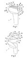
- the extendable seat arrangement 1 shown in Fig. 1, Fig. 2 and Fig. 3 comprises six seat elements 5a to 5f in a chain-like configuration. Each of the seat elements 5 is connected to one or two neighboring seat elements via a hinge 4a to 4e.
- the arrangement 1 is supported by a pillar 3 which is to be mounted on the floor of a vehicle's passenger room.
- a pillar 3 which is to be mounted on the floor of a vehicle's passenger room.
- at least one additional pillar can be used to support seat elements 5 in the extended state shown in Fig. 2 only, but not in the diminished state shown in Fig. 1 . If the arrangement is brought from the extended state to the diminished state the additional pillar(s) is/are removed.
- Another option is to fix at least one end seat element 5a, 5f in the extended state shown in Fig. 2 to another object (not shown).
- the extended state shown in Fig. 2 has a zig-zag configuration in which the longitudinal directions of the individual seat elements 5 follow a zig-zag path, if viewed from above.
- the extended state in Fig. 2 may be the only extended state intended, may be the fully extended state or may be an intermediate state (which means that the angles between the longitudinal directions of the seat elements 5 can be increased further).
- the diminished state shown in Fig. 1 may correspond to angles between the longitudinal directions of neighboring seat elements 5 of 0°.
- the angles in the diminished state i.e. the minimum possible angles, may be larger than 0°.
- the extendable seat arrangement may be fully occupied by one person 7 in the diminished state.
- the extended or intermediate state shown in Fig. 2 provides seating areas for several passengers (not shown in Fig. 2 ).
- the extendable seat arrangement 1 of Fig. 1 to Fig. 3 comprises in each case one protrusion 6a to 6e above the hinges 4a to 4e.
- the protrusion 6 may contain a part of the hinge 4.
- the protrusion 6 delimits the seating area defined by the neighboring seat elements 5.
- the protrusion 6 above the hinge 4 tapers towards the top end.
- the top end is preferably rounded for safety reasons.
- FIG. 4 shows a specific embodiment of the arrangement 1 of Fig. 1 to Fig. 3 .
- One seat element 5a at the end of the chain-like configuration is wider (in horizontal direction) than the other seat elements 5b to 5f.
- parts of the seating or leaning surfaces defined by the seat elements 5a to 5f are inclined so that the seating or leaning surfaces of the seat elements 5a to 5f can overlap each other (if viewed from the top). Therefore, very little space is required by the arrangement in the diminished state shown in Fig. 4 and one of the seat elements, namely seat element 5a, can be adapted to provide increased comfort due to padding or cushioning 2.
- Fig. 4 also shows that it is possible to use a hollow pillar 3 as support structure for supporting the arrangement onto the floor 8.
- Fig. 5 to Fig. 8 illustrate alternative seat arrangement.
- the seat arrangement 9 shown in Fig. 5 and Fig. 6 comprises only two seat elements 5a, 5b which are neighboring seat elements connected to each other via a hinge 4.
- the angle between the neighboring seat elements 5a, 5b is about 90°.
- the minimum angle between the seat elements 5a, 5b may be larger than 0°, as shown in Fig. 6 .
- the configuration illustrated by Fig. 7 and Fig. 8 is an example of the arrangement shown in Fig. 1 to Fig. 3 .
- the minimum angle in the diminished state ( Fig. 8 ) may be larger than 0°.
- the hinges 4 may be operated independently of each other so that the angle between the neighboring seat elements 5 can be adjusted individually. Therefore, many different states (not shown) between the fully extended state and the diminished state can be adjusted.
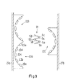
- Fig. 9 shows a seat arrangement 11 in the middle of a passenger room.
- "Middle" means in particular that the arrangement 11 is located half way in between two opposite outer sidewalls 21 a, 21 b of a vehicle's car body.
- the car body may be an extra wide car body having a width of 2.9 m or wider.
- Fig. 9 there are other seating areas 22a, 22b, 22c along the outer sidewalls 21, 21 b having in each case a plurality of seats 23a to 23e as shown in case of the seating area 22a.
- seating areas along the opposite outer sidewalls may be positioned directly visa-a-vis.
- the seating area 22c on the right hand side of Fig. 9 faces parts of two opposite seating areas 22a, 22b.
- the seat arrangement 11 in the middle of the passenger area comprises four seat elements 5a to 5d which are connected to their respective neighboring seat element 5 via a hinge 6a, 6b, 6c.
- Fig. 9 does not show the fully extended state, but an intermediate state of the seat arrangement 11.
- the seats and as well the seat elements of any embodiment of the extendable seat arrangement can be designed to enable perch seating in the sense of a passenger's position between standing and sitting.
- the passenger may lean on the seat arrangement while he or she transfers a part of his/her weight forces to the seat element or seat elements of the arrangement. Another part of the weight forces is directly transferred to the floor via the feet.
- the dimensions of at least one seat element and preferably of all seat elements of the seat arrangement in two horizontal directions perpendicular to each other are chosen in the following manner: the length (dimension in the first of the two directions) in the longitudinal direction mentioned above is at least three times larger than the width (dimension in the second of the two directions), preferably at least five times larger and most preferred at least seven times larger.
Landscapes
- Engineering & Computer Science (AREA)
- Aviation & Aerospace Engineering (AREA)
- Transportation (AREA)
- Mechanical Engineering (AREA)
- Seats For Vehicles (AREA)
Priority Applications (1)
| Application Number | Priority Date | Filing Date | Title |
|---|---|---|---|
| EP13189380.2A EP2862775B1 (de) | 2013-10-18 | 2013-10-18 | Anordnung mit Sitzen für eine Vielzahl von Fahrzeuginsassen und Verfahren zur Herstellung der Anordnung |
Applications Claiming Priority (1)
| Application Number | Priority Date | Filing Date | Title |
|---|---|---|---|
| EP13189380.2A EP2862775B1 (de) | 2013-10-18 | 2013-10-18 | Anordnung mit Sitzen für eine Vielzahl von Fahrzeuginsassen und Verfahren zur Herstellung der Anordnung |
Publications (2)
| Publication Number | Publication Date |
|---|---|
| EP2862775A1 true EP2862775A1 (de) | 2015-04-22 |
| EP2862775B1 EP2862775B1 (de) | 2016-07-13 |
Family
ID=49385158
Family Applications (1)
| Application Number | Title | Priority Date | Filing Date |
|---|---|---|---|
| EP13189380.2A Not-in-force EP2862775B1 (de) | 2013-10-18 | 2013-10-18 | Anordnung mit Sitzen für eine Vielzahl von Fahrzeuginsassen und Verfahren zur Herstellung der Anordnung |
Country Status (1)
| Country | Link |
|---|---|
| EP (1) | EP2862775B1 (de) |
Citations (4)
| Publication number | Priority date | Publication date | Assignee | Title |
|---|---|---|---|---|
| GB1551764A (en) * | 1975-05-15 | 1979-08-30 | Renault | Seat assemblies |
| EP0065494A1 (de) * | 1981-04-30 | 1982-11-24 | Renato Monzini | Personenkraftfahrzeug mit verschwenkter Sitzanordnung |
| EP1127788A1 (de) * | 2000-02-23 | 2001-08-29 | EADS Airbus GmbH | Passagiervorrichtung in einer Flugzeugpassagierkabine |
| WO2007141054A1 (de) | 2006-06-09 | 2007-12-13 | Siemens Transportation Systems Gmbh & Co. Kg | Steuerbare klappsitze |
-
2013
- 2013-10-18 EP EP13189380.2A patent/EP2862775B1/de not_active Not-in-force
Patent Citations (4)
| Publication number | Priority date | Publication date | Assignee | Title |
|---|---|---|---|---|
| GB1551764A (en) * | 1975-05-15 | 1979-08-30 | Renault | Seat assemblies |
| EP0065494A1 (de) * | 1981-04-30 | 1982-11-24 | Renato Monzini | Personenkraftfahrzeug mit verschwenkter Sitzanordnung |
| EP1127788A1 (de) * | 2000-02-23 | 2001-08-29 | EADS Airbus GmbH | Passagiervorrichtung in einer Flugzeugpassagierkabine |
| WO2007141054A1 (de) | 2006-06-09 | 2007-12-13 | Siemens Transportation Systems Gmbh & Co. Kg | Steuerbare klappsitze |
Also Published As
| Publication number | Publication date |
|---|---|
| EP2862775B1 (de) | 2016-07-13 |
Similar Documents
| Publication | Publication Date | Title |
|---|---|---|
| US11312497B2 (en) | Seat arrangement, in particular for an airplane | |
| US9475407B2 (en) | Folding vehicle seat | |
| EP2697116B1 (de) | Passgiersitzanordnungen | |
| US8449028B2 (en) | Vehicle seat | |
| US20050194828A1 (en) | Vehicle seating with shared armrests | |
| BR102012013150A2 (pt) | Assento que pode ser convertido em cama | |
| US9120574B2 (en) | Passenger seat | |
| CN104802993A (zh) | 扶手以及包括该扶手的座椅布置 | |
| US8783771B2 (en) | Extendable seat pan assembly with comfort spring | |
| US11230208B2 (en) | Rail and vehicle seat | |
| KR20050097982A (ko) | 비행기와 같은 운송수단의 승객용 객실에 설치될 모듈 | |
| CN112498392A (zh) | 用于运输工具的座椅装置 | |
| WO2011077366A1 (en) | Improvements relating to passenger vehicle seating | |
| EP2899125A1 (de) | Sitzanordnung, Flugzeugkabine sowie Armlehne und Sitz oder Sitzgruppe zur Verwendung darin | |
| JP6884120B2 (ja) | 長距離夜行バスのシート構造 | |
| US11905019B2 (en) | Passenger cabin area and aircraft having a passenger cabin area | |
| EP2862775B1 (de) | Anordnung mit Sitzen für eine Vielzahl von Fahrzeuginsassen und Verfahren zur Herstellung der Anordnung | |
| EP2578447B1 (de) | Rückhaltevorrichtung für Passagiertransportfahrzeuge und Passagiertransportfahrzeug mit einer solchen Vorrichtung | |
| US20160159372A1 (en) | Two-floor passenger railway car and train comprising such a car | |
| JP4589377B2 (ja) | 航空機の客室の内部レイアウト | |
| WO2018020767A1 (ja) | 車両用シート | |
| US20150360702A1 (en) | Rail Vehicle | |
| EP3552965A1 (de) | Sitzanordnung für fahrzeuge | |
| JP2007168609A (ja) | 車両用シート構造 | |
| KR100502144B1 (ko) | 버스용 시트 |
Legal Events
| Date | Code | Title | Description |
|---|---|---|---|
| PUAI | Public reference made under article 153(3) epc to a published international application that has entered the european phase |
Free format text: ORIGINAL CODE: 0009012 |
|
| 17P | Request for examination filed |
Effective date: 20131018 |
|
| AK | Designated contracting states |
Kind code of ref document: A1 Designated state(s): AL AT BE BG CH CY CZ DE DK EE ES FI FR GB GR HR HU IE IS IT LI LT LU LV MC MK MT NL NO PL PT RO RS SE SI SK SM TR |
|
| AX | Request for extension of the european patent |
Extension state: BA ME |
|
| R17P | Request for examination filed (corrected) |
Effective date: 20150918 |
|
| RBV | Designated contracting states (corrected) |
Designated state(s): AL AT BE BG CH CY CZ DE DK EE ES FI FR GB GR HR HU IE IS IT LI LT LU LV MC MK MT NL NO PL PT RO RS SE SI SK SM TR |
|
| GRAP | Despatch of communication of intention to grant a patent |
Free format text: ORIGINAL CODE: EPIDOSNIGR1 |
|
| INTG | Intention to grant announced |
Effective date: 20160205 |
|
| GRAS | Grant fee paid |
Free format text: ORIGINAL CODE: EPIDOSNIGR3 |
|
| GRAA | (expected) grant |
Free format text: ORIGINAL CODE: 0009210 |
|
| AK | Designated contracting states |
Kind code of ref document: B1 Designated state(s): AL AT BE BG CH CY CZ DE DK EE ES FI FR GB GR HR HU IE IS IT LI LT LU LV MC MK MT NL NO PL PT RO RS SE SI SK SM TR |
|
| REG | Reference to a national code |
Ref country code: GB Ref legal event code: FG4D |
|
| REG | Reference to a national code |
Ref country code: AT Ref legal event code: REF Ref document number: 812025 Country of ref document: AT Kind code of ref document: T Effective date: 20160715 Ref country code: CH Ref legal event code: EP |
|
| REG | Reference to a national code |
Ref country code: IE Ref legal event code: FG4D |
|
| REG | Reference to a national code |
Ref country code: CH Ref legal event code: NV Representative=s name: PATENTANWALT DIPL.-ING. (UNI.) WOLFGANG HEISEL, CH |
|
| REG | Reference to a national code |
Ref country code: DE Ref legal event code: R096 Ref document number: 602013009301 Country of ref document: DE |
|
| REG | Reference to a national code |
Ref country code: SE Ref legal event code: TRGR |
|
| REG | Reference to a national code |
Ref country code: FR Ref legal event code: PLFP Year of fee payment: 4 |
|
| REG | Reference to a national code |
Ref country code: LT Ref legal event code: MG4D |
|
| REG | Reference to a national code |
Ref country code: NL Ref legal event code: MP Effective date: 20160713 |
|
| PG25 | Lapsed in a contracting state [announced via postgrant information from national office to epo] |
Ref country code: NO Free format text: LAPSE BECAUSE OF FAILURE TO SUBMIT A TRANSLATION OF THE DESCRIPTION OR TO PAY THE FEE WITHIN THE PRESCRIBED TIME-LIMIT Effective date: 20161013 Ref country code: LT Free format text: LAPSE BECAUSE OF FAILURE TO SUBMIT A TRANSLATION OF THE DESCRIPTION OR TO PAY THE FEE WITHIN THE PRESCRIBED TIME-LIMIT Effective date: 20160713 Ref country code: FI Free format text: LAPSE BECAUSE OF FAILURE TO SUBMIT A TRANSLATION OF THE DESCRIPTION OR TO PAY THE FEE WITHIN THE PRESCRIBED TIME-LIMIT Effective date: 20160713 Ref country code: HR Free format text: LAPSE BECAUSE OF FAILURE TO SUBMIT A TRANSLATION OF THE DESCRIPTION OR TO PAY THE FEE WITHIN THE PRESCRIBED TIME-LIMIT Effective date: 20160713 Ref country code: IS Free format text: LAPSE BECAUSE OF FAILURE TO SUBMIT A TRANSLATION OF THE DESCRIPTION OR TO PAY THE FEE WITHIN THE PRESCRIBED TIME-LIMIT Effective date: 20161113 Ref country code: NL Free format text: LAPSE BECAUSE OF FAILURE TO SUBMIT A TRANSLATION OF THE DESCRIPTION OR TO PAY THE FEE WITHIN THE PRESCRIBED TIME-LIMIT Effective date: 20160713 Ref country code: RS Free format text: LAPSE BECAUSE OF FAILURE TO SUBMIT A TRANSLATION OF THE DESCRIPTION OR TO PAY THE FEE WITHIN THE PRESCRIBED TIME-LIMIT Effective date: 20160713 |
|
| PG25 | Lapsed in a contracting state [announced via postgrant information from national office to epo] |
Ref country code: ES Free format text: LAPSE BECAUSE OF FAILURE TO SUBMIT A TRANSLATION OF THE DESCRIPTION OR TO PAY THE FEE WITHIN THE PRESCRIBED TIME-LIMIT Effective date: 20160713 Ref country code: PL Free format text: LAPSE BECAUSE OF FAILURE TO SUBMIT A TRANSLATION OF THE DESCRIPTION OR TO PAY THE FEE WITHIN THE PRESCRIBED TIME-LIMIT Effective date: 20160713 Ref country code: PT Free format text: LAPSE BECAUSE OF FAILURE TO SUBMIT A TRANSLATION OF THE DESCRIPTION OR TO PAY THE FEE WITHIN THE PRESCRIBED TIME-LIMIT Effective date: 20161114 Ref country code: GR Free format text: LAPSE BECAUSE OF FAILURE TO SUBMIT A TRANSLATION OF THE DESCRIPTION OR TO PAY THE FEE WITHIN THE PRESCRIBED TIME-LIMIT Effective date: 20161014 Ref country code: LV Free format text: LAPSE BECAUSE OF FAILURE TO SUBMIT A TRANSLATION OF THE DESCRIPTION OR TO PAY THE FEE WITHIN THE PRESCRIBED TIME-LIMIT Effective date: 20160713 |
|
| REG | Reference to a national code |
Ref country code: DE Ref legal event code: R097 Ref document number: 602013009301 Country of ref document: DE |
|
| PG25 | Lapsed in a contracting state [announced via postgrant information from national office to epo] |
Ref country code: RO Free format text: LAPSE BECAUSE OF FAILURE TO SUBMIT A TRANSLATION OF THE DESCRIPTION OR TO PAY THE FEE WITHIN THE PRESCRIBED TIME-LIMIT Effective date: 20160713 Ref country code: EE Free format text: LAPSE BECAUSE OF FAILURE TO SUBMIT A TRANSLATION OF THE DESCRIPTION OR TO PAY THE FEE WITHIN THE PRESCRIBED TIME-LIMIT Effective date: 20160713 |
|
| PLBE | No opposition filed within time limit |
Free format text: ORIGINAL CODE: 0009261 |
|
| STAA | Information on the status of an ep patent application or granted ep patent |
Free format text: STATUS: NO OPPOSITION FILED WITHIN TIME LIMIT |
|
| PG25 | Lapsed in a contracting state [announced via postgrant information from national office to epo] |
Ref country code: CZ Free format text: LAPSE BECAUSE OF FAILURE TO SUBMIT A TRANSLATION OF THE DESCRIPTION OR TO PAY THE FEE WITHIN THE PRESCRIBED TIME-LIMIT Effective date: 20160713 Ref country code: DK Free format text: LAPSE BECAUSE OF FAILURE TO SUBMIT A TRANSLATION OF THE DESCRIPTION OR TO PAY THE FEE WITHIN THE PRESCRIBED TIME-LIMIT Effective date: 20160713 Ref country code: SK Free format text: LAPSE BECAUSE OF FAILURE TO SUBMIT A TRANSLATION OF THE DESCRIPTION OR TO PAY THE FEE WITHIN THE PRESCRIBED TIME-LIMIT Effective date: 20160713 Ref country code: BG Free format text: LAPSE BECAUSE OF FAILURE TO SUBMIT A TRANSLATION OF THE DESCRIPTION OR TO PAY THE FEE WITHIN THE PRESCRIBED TIME-LIMIT Effective date: 20161013 Ref country code: SM Free format text: LAPSE BECAUSE OF FAILURE TO SUBMIT A TRANSLATION OF THE DESCRIPTION OR TO PAY THE FEE WITHIN THE PRESCRIBED TIME-LIMIT Effective date: 20160713 |
|
| 26N | No opposition filed |
Effective date: 20170418 |
|
| REG | Reference to a national code |
Ref country code: IE Ref legal event code: MM4A |
|
| PG25 | Lapsed in a contracting state [announced via postgrant information from national office to epo] |
Ref country code: SI Free format text: LAPSE BECAUSE OF FAILURE TO SUBMIT A TRANSLATION OF THE DESCRIPTION OR TO PAY THE FEE WITHIN THE PRESCRIBED TIME-LIMIT Effective date: 20160713 Ref country code: LU Free format text: LAPSE BECAUSE OF NON-PAYMENT OF DUE FEES Effective date: 20161018 |
|
| REG | Reference to a national code |
Ref country code: FR Ref legal event code: PLFP Year of fee payment: 5 |
|
| PG25 | Lapsed in a contracting state [announced via postgrant information from national office to epo] |
Ref country code: IE Free format text: LAPSE BECAUSE OF NON-PAYMENT OF DUE FEES Effective date: 20161018 |
|
| PG25 | Lapsed in a contracting state [announced via postgrant information from national office to epo] |
Ref country code: HU Free format text: LAPSE BECAUSE OF FAILURE TO SUBMIT A TRANSLATION OF THE DESCRIPTION OR TO PAY THE FEE WITHIN THE PRESCRIBED TIME-LIMIT; INVALID AB INITIO Effective date: 20131018 |
|
| PG25 | Lapsed in a contracting state [announced via postgrant information from national office to epo] |
Ref country code: MT Free format text: LAPSE BECAUSE OF NON-PAYMENT OF DUE FEES Effective date: 20161031 Ref country code: CY Free format text: LAPSE BECAUSE OF FAILURE TO SUBMIT A TRANSLATION OF THE DESCRIPTION OR TO PAY THE FEE WITHIN THE PRESCRIBED TIME-LIMIT Effective date: 20160713 Ref country code: MK Free format text: LAPSE BECAUSE OF FAILURE TO SUBMIT A TRANSLATION OF THE DESCRIPTION OR TO PAY THE FEE WITHIN THE PRESCRIBED TIME-LIMIT Effective date: 20160713 Ref country code: MC Free format text: LAPSE BECAUSE OF FAILURE TO SUBMIT A TRANSLATION OF THE DESCRIPTION OR TO PAY THE FEE WITHIN THE PRESCRIBED TIME-LIMIT Effective date: 20160713 |
|
| REG | Reference to a national code |
Ref country code: FR Ref legal event code: PLFP Year of fee payment: 6 |
|
| PG25 | Lapsed in a contracting state [announced via postgrant information from national office to epo] |
Ref country code: AL Free format text: LAPSE BECAUSE OF FAILURE TO SUBMIT A TRANSLATION OF THE DESCRIPTION OR TO PAY THE FEE WITHIN THE PRESCRIBED TIME-LIMIT Effective date: 20160713 Ref country code: TR Free format text: LAPSE BECAUSE OF FAILURE TO SUBMIT A TRANSLATION OF THE DESCRIPTION OR TO PAY THE FEE WITHIN THE PRESCRIBED TIME-LIMIT Effective date: 20160713 |
|
| REG | Reference to a national code |
Ref country code: AT Ref legal event code: UEP Ref document number: 812025 Country of ref document: AT Kind code of ref document: T Effective date: 20160713 |
|
| PGFP | Annual fee paid to national office [announced via postgrant information from national office to epo] |
Ref country code: AT Payment date: 20211021 Year of fee payment: 9 Ref country code: GB Payment date: 20211022 Year of fee payment: 9 Ref country code: SE Payment date: 20211020 Year of fee payment: 9 Ref country code: DE Payment date: 20211020 Year of fee payment: 9 |
|
| PGFP | Annual fee paid to national office [announced via postgrant information from national office to epo] |
Ref country code: IT Payment date: 20211028 Year of fee payment: 9 Ref country code: FR Payment date: 20211022 Year of fee payment: 9 Ref country code: CH Payment date: 20211020 Year of fee payment: 9 Ref country code: BE Payment date: 20211020 Year of fee payment: 9 |
|
| REG | Reference to a national code |
Ref country code: DE Ref legal event code: R119 Ref document number: 602013009301 Country of ref document: DE |
|
| REG | Reference to a national code |
Ref country code: SE Ref legal event code: EUG |
|
| REG | Reference to a national code |
Ref country code: CH Ref legal event code: PL |
|
| REG | Reference to a national code |
Ref country code: AT Ref legal event code: MM01 Ref document number: 812025 Country of ref document: AT Kind code of ref document: T Effective date: 20221018 |
|
| REG | Reference to a national code |
Ref country code: BE Ref legal event code: MM Effective date: 20221031 |
|
| GBPC | Gb: european patent ceased through non-payment of renewal fee |
Effective date: 20221018 |
|
| PG25 | Lapsed in a contracting state [announced via postgrant information from national office to epo] |
Ref country code: LI Free format text: LAPSE BECAUSE OF NON-PAYMENT OF DUE FEES Effective date: 20221031 Ref country code: FR Free format text: LAPSE BECAUSE OF NON-PAYMENT OF DUE FEES Effective date: 20221031 Ref country code: DE Free format text: LAPSE BECAUSE OF NON-PAYMENT OF DUE FEES Effective date: 20230503 Ref country code: CH Free format text: LAPSE BECAUSE OF NON-PAYMENT OF DUE FEES Effective date: 20221031 Ref country code: AT Free format text: LAPSE BECAUSE OF NON-PAYMENT OF DUE FEES Effective date: 20221018 |
|
| PG25 | Lapsed in a contracting state [announced via postgrant information from national office to epo] |
Ref country code: SE Free format text: LAPSE BECAUSE OF NON-PAYMENT OF DUE FEES Effective date: 20221019 |
|
| PG25 | Lapsed in a contracting state [announced via postgrant information from national office to epo] |
Ref country code: BE Free format text: LAPSE BECAUSE OF NON-PAYMENT OF DUE FEES Effective date: 20221031 |
|
| PG25 | Lapsed in a contracting state [announced via postgrant information from national office to epo] |
Ref country code: IT Free format text: LAPSE BECAUSE OF NON-PAYMENT OF DUE FEES Effective date: 20221018 Ref country code: GB Free format text: LAPSE BECAUSE OF NON-PAYMENT OF DUE FEES Effective date: 20221018 |