EP3552965A1 - Sitzanordnung für fahrzeuge - Google Patents
Sitzanordnung für fahrzeuge Download PDFInfo
- Publication number
- EP3552965A1 EP3552965A1 EP18195990.9A EP18195990A EP3552965A1 EP 3552965 A1 EP3552965 A1 EP 3552965A1 EP 18195990 A EP18195990 A EP 18195990A EP 3552965 A1 EP3552965 A1 EP 3552965A1
- Authority
- EP
- European Patent Office
- Prior art keywords
- seat
- uprights
- floor
- seat assembly
- ceiling
- Prior art date
- Legal status (The legal status is an assumption and is not a legal conclusion. Google has not performed a legal analysis and makes no representation as to the accuracy of the status listed.)
- Withdrawn
Links
- 230000000712 assembly Effects 0.000 claims abstract description 49
- 238000000429 assembly Methods 0.000 claims abstract description 49
- 238000009434 installation Methods 0.000 description 5
- 238000004873 anchoring Methods 0.000 description 3
Images


Classifications
-
- B—PERFORMING OPERATIONS; TRANSPORTING
- B64—AIRCRAFT; AVIATION; COSMONAUTICS
- B64D—EQUIPMENT FOR FITTING IN OR TO AIRCRAFT; FLIGHT SUITS; PARACHUTES; ARRANGEMENT OR MOUNTING OF POWER PLANTS OR PROPULSION TRANSMISSIONS IN AIRCRAFT
- B64D11/00—Passenger or crew accommodation; Flight-deck installations not otherwise provided for
- B64D11/06—Arrangements of seats, or adaptations or details specially adapted for aircraft seats
- B64D11/0611—Arrangements of seats, or adaptations or details specially adapted for aircraft seats with means for holding the passenger in a standing position
-
- B—PERFORMING OPERATIONS; TRANSPORTING
- B64—AIRCRAFT; AVIATION; COSMONAUTICS
- B64D—EQUIPMENT FOR FITTING IN OR TO AIRCRAFT; FLIGHT SUITS; PARACHUTES; ARRANGEMENT OR MOUNTING OF POWER PLANTS OR PROPULSION TRANSMISSIONS IN AIRCRAFT
- B64D11/00—Passenger or crew accommodation; Flight-deck installations not otherwise provided for
- B64D11/06—Arrangements of seats, or adaptations or details specially adapted for aircraft seats
- B64D11/0696—Means for fastening seats to floors, e.g. to floor rails
-
- B—PERFORMING OPERATIONS; TRANSPORTING
- B64—AIRCRAFT; AVIATION; COSMONAUTICS
- B64D—EQUIPMENT FOR FITTING IN OR TO AIRCRAFT; FLIGHT SUITS; PARACHUTES; ARRANGEMENT OR MOUNTING OF POWER PLANTS OR PROPULSION TRANSMISSIONS IN AIRCRAFT
- B64D11/00—Passenger or crew accommodation; Flight-deck installations not otherwise provided for
- B64D11/06—Arrangements of seats, or adaptations or details specially adapted for aircraft seats
- B64D11/0697—Seats suspended from aircraft ceiling
Definitions
- the invention relates to a seat assembly for vehicles.
- the invention relates to a seat assembly designed to be mounted inside vehicles where the installation of a large number of seat assemblies is required is required in relation to the space available for the relative installation.
- the above-mentioned seat assembly is particularly suitable for being mounted on board aircraft, even though they can be installed, advantageously, also inside trains, buses, ships or other types of vehicles.
- the aim of the invention is therefore to provide a seat assembly for vehicles which has an adequate comfort for the passenger and allows, at the same time, a high density of seat assemblies to be obtained inside the vehicles.
- Another aim of the invention is to provide a seat assembly for vehicles which allows a better distribution of the loads to be achieved inside the vehicles in which it is installed.
- a further aim of the invention is to provide a seat assembly which is relatively easy to install inside vehicles.
- the specific object of this invention is therefore a seat assembly of the type which can be installed on board a vehicle in which are defined a floor and a ceiling, said seat assembly comprising: a backrest; a seat comprising two side portions and an intermediate portion positioned between said side portions, wherein said intermediate portion protrudes, forwards, with respect to said side portions to allow a person to sit on the seat in a substantially upright position; and a support structure comprising: at least two uprights to which are connected said backrest and said seat; first connection means for connecting, in use, said at least two uprights to said floor; and second connection means for connecting, in use, said at least two uprights to said ceiling, in such a way as to distribute, in use, the load of said seat assemblies, partly on said floor and partly on said ceiling.
- said seat may be shaped, substantially, in the form of a bicycle saddle.
- said second connection means comprise a reticular structure connected to a top portion of said at least two uprights.
- said reticular structure can comprise a plurality of devices for absorbing vibrations in different directions.
- said second connection means can comprise at least two connection elements for connecting, in an articulated fashion, said at least two uprights to said reticular structure.
- said seat assembly comprises an adjustment mechanism for adjusting the height of said seat.
- said seat assembly may comprise at least two armrests positioned at opposite sides of said backrest and a respective adjustment mechanism for adjusting the height of said at least two armrests.
- said first connection means can comprise at least two connection elements for connecting, in use, said at least two uprights to said floor in an articulated fashion.
- said seat assembly comprises a transversal element connected to said at least two uprights and positioned beneath said seat in such a way that between said transversal element and said at least two uprights is defined a space for housing, in use, at least one bag.
- the object of this invention is also a series of seat assemblies of the type which can be installed on board a vehicle in which are defined a floor and a ceiling, said series of seat assemblies comprising: a plurality of backrests; a plurality of seats positioned aligned with each other, each seat comprising two side portions and an intermediate portion positioned between said side portions, wherein said intermediate portion protrudes, forwards, with respect to said side portions to allow a person to sit on the seat in a substantially upright position; and a support structure comprising: at least two uprights to which are connected said plurality of backrests and said plurality of seats; first connection means for connecting, in use, said at least two uprights to said floor; and second connection means for connecting, in use, said at least two uprights to said ceiling, in such a way as to distribute, in use, the load of said series of seat assemblies, partly on said floor and partly on said ceiling.
- Another object of the invention is a vehicle comprising a fuselage, in which are defined a floor and a ceiling, and at least one seat assembly of the type describe above, connected to said floor and to said ceiling.
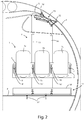
- the numeral 1 denotes a group of seat assemblies formed, in this specific case, by three seat assemblies, in particular a central seat assembly 1b and two side seat assemblies 1a, 1c positioned aligned with the central seat assembly 1b.
- the above-mentioned group of seat assemblies could, however, also be composed of a different number of seat assemblies, more or less than three and, therefore, also by a single seat assembly.
- each seat assembly 1a, 1b, 1c comprises a backrest 2 and a seat 3 configured in the form of a bicycle saddle, that is, with a respective central front part 3b protruding with respect to the two side portions 3a, 3c.
- This particular shape of the seat 3 allows the passengers to sit on the seats in a more upright position compared with traditional seat assemblies, which are, on the other hand, normally configured so as to allow sitting with the femoral section of the legs parallel to the floor.
- the shape of the seat 3 of the seat assemblies 1a, 1b, 1c therefore allows the overall dimensions determined by the passengers in a seated position to be reduced and to therefore increase the number of seat assemblies which can be installed per unit length along the longitudinal axis X of the fuselage F.
- the group of seat assemblies 1 is supported by a support structure 4 which comprises a transversal frame 5, on which are mounted the seat assemblies 1a, 1b, 1c by means of a respective adjustment mechanism (not visible) which allows the height of each seat assembly 1a, 1b, 1c to be varied in an independent fashion.
- transversal frame 5 On the transversal frame 5 are also mounted the two inner armrests 15, 16 and the two outer armrests 7, 8 of the group of seat assemblies 1, with a respective adjustment mechanism 15', 16', 7', 8' for allowing the variation in height of each armrest.
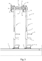
- the support structure 4 also comprises two vertical uprights 13, 14 to which the transversal frame 5 is rigidly connected, at the opposite sides of the central seat assembly 1b, that is, between the central seat assembly 1b and the side seat assembly 1a, and between the central seat assembly 1b and the other side seat assembly 1c.
- the support structure 4 also comprises a lower framework 17 fixed at the base of each vertical upright 13, 14.
- transversal tubular element 18 protruding forwards and having the function of containing any hand luggage for the passengers, which should be placed in the space beneath the seats 3, between the transversal tubular element 18 and the vertical uprights 13, 14.
- the transversal tubular element 18 therefore prevents the hand luggage placed in the above-mentioned space from moving forwards along the longitudinal axis X during the various flight phases, in particular during landing when the aircraft is subjected to a sharp deceleration.
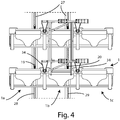
- each lower fixing element 19, 20 comprises a lower body 21 and an upper body 22 which can be connected by means of a screw 23 to the lower body 21.
- each lower fixing element 19, 20 there is a through hole 24 for making, with the above-mentioned lower framework 17, a connection rotatable about a transversal axis Y at right-angles to the above-mentioned longitudinal axis X by means of a respective pin position through the through hole 24.
- each lower fixing element 19, 20 On the bottom of the upper body 22 of each lower fixing element 19, 20 there are also two protruding portions 25, 26 configured for the fixing to the floor P as described below.
- a track 27 that is to say, a pair of "seat tracks", which extends parallel to the longitudinal axis X in the floor P of the fuselage F.
- each cavity On the top surfaces of the track 27 there are a first row of cavities 28 and a second row of cavities 29, wherein each cavity has an upper, narrow, portion 30 and a lower, wide, portion 31 (see Figure 8 ) configured for receiving, under pressure, together with the lower portion 31 of an adjacent cavity, the two protruding portions 25, 26 of the upper body 22 of each lower fixing element 19, 20, by screwing the above-mentioned screw 23.
- the lower framework 17 is connected to the track 27, and therefore also indirectly also to the floor P of the fuselage F, only at the two lower fixing elements 19, 20.
- a reticular structure 33 which extends parallel to the above-mentioned longitudinal axis X, is fixed by means of anchoring elements 32.
- each upper connecting element 34 is in the form of a substantially triangular element hinged to the reticular structure 33 and to one of the above-mentioned vertical uprights 13, 14, in such a way as to allow, in the hinge areas, a slight rotation about a respective axis parallel to the above-mentioned transversal axis Y, allowing the two vertical uprights 13, 14 to perform small movements in a substantially vertical direction.
- the reticular structure 33 there are also a plurality of devices 35 for absorbing vibrations in different directions.
- the particular shape of the seat assemblies 1a, 1b, 1c and of the relative support structure 4 allows the installation, on board the aircraft, of a high number of seat assemblies per unit length, in terms of the linear dimension along the longitudinal axis X.
- the technical solution described above allows the load of the seat assemblies to be distributed partly on the floor and partly on the upper cover of the fuselage of the aircraft.
- the distribution of the loads is particularly advantageous if a large number of seat assemblies is to be installed on the aircraft per unit length along the longitudinal axis X.
- the seat assemblies described above can also be conveniently installed on board vehicles other than aircraft, such as, for example trains, buses or ships, allowing advantages to be obtained, equally, in terms of high density of seat assemblies which can be located in the installation compartment and adequate comfort for the passengers.
Landscapes
- Engineering & Computer Science (AREA)
- Aviation & Aerospace Engineering (AREA)
- Seats For Vehicles (AREA)
Applications Claiming Priority (1)
| Application Number | Priority Date | Filing Date | Title |
|---|---|---|---|
| IT202018000002320U IT201800002320U1 (it) | 2018-04-09 | 2018-04-09 | Sedile per veicoli. |
Publications (1)
| Publication Number | Publication Date |
|---|---|
| EP3552965A1 true EP3552965A1 (de) | 2019-10-16 |
Family
ID=63713610
Family Applications (1)
| Application Number | Title | Priority Date | Filing Date |
|---|---|---|---|
| EP18195990.9A Withdrawn EP3552965A1 (de) | 2018-04-09 | 2018-09-21 | Sitzanordnung für fahrzeuge |
Country Status (3)
| Country | Link |
|---|---|
| EP (1) | EP3552965A1 (de) |
| CN (1) | CN110356565A (de) |
| IT (1) | IT201800002320U1 (de) |
Cited By (3)
| Publication number | Priority date | Publication date | Assignee | Title |
|---|---|---|---|---|
| WO2024015807A1 (en) * | 2022-07-13 | 2024-01-18 | Supernal, Llc | Seat mounted to structural column and methods thereof |
| EP4255807A4 (de) * | 2020-12-01 | 2024-10-02 | The Nordam Group LLC | Flugzeugsitzmodul |
| EP4606704A1 (de) * | 2024-02-23 | 2025-08-27 | AIRBUS HELICOPTERS DEUTSCHLAND GmbH | Sitzträger für ein drehflügelflugzeug zur aufnahme von sitzpfosten einer sitzbankvorrichtung |
Citations (5)
| Publication number | Priority date | Publication date | Assignee | Title |
|---|---|---|---|---|
| DE10008258A1 (de) * | 2000-02-23 | 2001-09-20 | Eads Airbus Gmbh | Fluzeugpassagierkabine mit mindestens einer Passagiertransportvorrichtung |
| US20020000490A1 (en) * | 2000-02-23 | 2002-01-03 | Angerami Jade Gaeta | Aircraft passenger cabin with a stand for transporting a passenger in an upright position |
| US20040100138A1 (en) * | 2002-11-27 | 2004-05-27 | Johnson Glenn A | Aircraft passenger seat with forward arm rest pivot |
| US20110260482A1 (en) * | 2010-04-26 | 2011-10-27 | Ferno-Washington, Inc. | Emergency vehicle patient transport systems |
| US20140159444A1 (en) * | 2012-12-12 | 2014-06-12 | Airbus Operations (Sas) | Seating device comprising a forward-foldable backrest |
-
2018
- 2018-04-09 IT IT202018000002320U patent/IT201800002320U1/it unknown
- 2018-09-21 EP EP18195990.9A patent/EP3552965A1/de not_active Withdrawn
- 2018-11-09 CN CN201811329270.1A patent/CN110356565A/zh active Pending
Patent Citations (5)
| Publication number | Priority date | Publication date | Assignee | Title |
|---|---|---|---|---|
| DE10008258A1 (de) * | 2000-02-23 | 2001-09-20 | Eads Airbus Gmbh | Fluzeugpassagierkabine mit mindestens einer Passagiertransportvorrichtung |
| US20020000490A1 (en) * | 2000-02-23 | 2002-01-03 | Angerami Jade Gaeta | Aircraft passenger cabin with a stand for transporting a passenger in an upright position |
| US20040100138A1 (en) * | 2002-11-27 | 2004-05-27 | Johnson Glenn A | Aircraft passenger seat with forward arm rest pivot |
| US20110260482A1 (en) * | 2010-04-26 | 2011-10-27 | Ferno-Washington, Inc. | Emergency vehicle patient transport systems |
| US20140159444A1 (en) * | 2012-12-12 | 2014-06-12 | Airbus Operations (Sas) | Seating device comprising a forward-foldable backrest |
Cited By (3)
| Publication number | Priority date | Publication date | Assignee | Title |
|---|---|---|---|---|
| EP4255807A4 (de) * | 2020-12-01 | 2024-10-02 | The Nordam Group LLC | Flugzeugsitzmodul |
| WO2024015807A1 (en) * | 2022-07-13 | 2024-01-18 | Supernal, Llc | Seat mounted to structural column and methods thereof |
| EP4606704A1 (de) * | 2024-02-23 | 2025-08-27 | AIRBUS HELICOPTERS DEUTSCHLAND GmbH | Sitzträger für ein drehflügelflugzeug zur aufnahme von sitzpfosten einer sitzbankvorrichtung |
Also Published As
| Publication number | Publication date |
|---|---|
| CN110356565A (zh) | 2019-10-22 |
| IT201800002320U1 (it) | 2019-10-09 |
Similar Documents
| Publication | Publication Date | Title |
|---|---|---|
| EP3608227B1 (de) | Flugzeuginnenkonfiguration mit flexiblem nutzraum | |
| US8939507B2 (en) | Backrest for a vehicle seat | |
| US7025306B2 (en) | Individual module for aircraft passengers | |
| US11498682B2 (en) | Arrangement of individual seats for passengers of an aeroplane equipped with screen supports forming a separating wall | |
| US11453501B2 (en) | Arrangement of individual seats for passengers of an aeroplane | |
| US8544796B2 (en) | Passenger seat assembly with associated floor panel and aircraft sidewall attachment, and method | |
| US7484795B2 (en) | Process for moduling the interior space of a vehicle and a seat for performing this process | |
| US20150091342A1 (en) | Passenger seating assemblies and aspects thereof | |
| EP3838759B1 (de) | Sitzanordnung | |
| JP2015503480A (ja) | 航空機の乗客用座席及び座席旋回アセンブリ | |
| US5800013A (en) | Vehicle passenger seating | |
| EP3608168B1 (de) | Sitzeinheit und bodenstruktur dafür | |
| EP3608161B1 (de) | Struktur für sitzeinheit, sitzeinheit und befestigungsverfahren dafür | |
| EP3552965A1 (de) | Sitzanordnung für fahrzeuge | |
| US11673671B2 (en) | Passenger seating arrangement | |
| EP3608167B1 (de) | Hintere schalenstruktur und sitzeinheit | |
| US4768832A (en) | Adjustable-width seating for vehicles | |
| CN111498116A (zh) | 用于载具的乘客舱室以及具有至少一个此类舱室的载具 | |
| EP0348096A2 (de) | Fahrzeugpassagierbestuhlung | |
| EP3608162B1 (de) | Sitzeinheit und befestigungsverfahren dafür |
Legal Events
| Date | Code | Title | Description |
|---|---|---|---|
| PUAI | Public reference made under article 153(3) epc to a published international application that has entered the european phase |
Free format text: ORIGINAL CODE: 0009012 |
|
| STAA | Information on the status of an ep patent application or granted ep patent |
Free format text: STATUS: THE APPLICATION HAS BEEN PUBLISHED |
|
| AK | Designated contracting states |
Kind code of ref document: A1 Designated state(s): AL AT BE BG CH CY CZ DE DK EE ES FI FR GB GR HR HU IE IS IT LI LT LU LV MC MK MT NL NO PL PT RO RS SE SI SK SM TR |
|
| AX | Request for extension of the european patent |
Extension state: BA ME |
|
| STAA | Information on the status of an ep patent application or granted ep patent |
Free format text: STATUS: THE APPLICATION IS DEEMED TO BE WITHDRAWN |
|
| 18D | Application deemed to be withdrawn |
Effective date: 20200603 |