EP2862756A1 - Dispositif de réglage d'un volet avant et véhicule automobile associé - Google Patents
Dispositif de réglage d'un volet avant et véhicule automobile associé Download PDFInfo
- Publication number
- EP2862756A1 EP2862756A1 EP20140002921 EP14002921A EP2862756A1 EP 2862756 A1 EP2862756 A1 EP 2862756A1 EP 20140002921 EP20140002921 EP 20140002921 EP 14002921 A EP14002921 A EP 14002921A EP 2862756 A1 EP2862756 A1 EP 2862756A1
- Authority
- EP
- European Patent Office
- Prior art keywords
- adjusting device
- front flap
- drive
- designed
- control
- Prior art date
- Legal status (The legal status is an assumption and is not a legal conclusion. Google has not performed a legal analysis and makes no representation as to the accuracy of the status listed.)
- Granted
Links
- 230000008878 coupling Effects 0.000 claims abstract description 6
- 238000010168 coupling process Methods 0.000 claims abstract description 6
- 238000005859 coupling reaction Methods 0.000 claims abstract description 6
- 230000007246 mechanism Effects 0.000 claims abstract description 4
- 230000006378 damage Effects 0.000 claims description 11
- 238000012423 maintenance Methods 0.000 claims description 6
- 230000009467 reduction Effects 0.000 claims description 3
- 230000001154 acute effect Effects 0.000 description 1
- 238000001514 detection method Methods 0.000 description 1
- 230000007613 environmental effect Effects 0.000 description 1
- 238000009434 installation Methods 0.000 description 1
- 230000008439 repair process Effects 0.000 description 1
Images

Classifications
-
- B—PERFORMING OPERATIONS; TRANSPORTING
- B60—VEHICLES IN GENERAL
- B60R—VEHICLES, VEHICLE FITTINGS, OR VEHICLE PARTS, NOT OTHERWISE PROVIDED FOR
- B60R21/00—Arrangements or fittings on vehicles for protecting or preventing injuries to occupants or pedestrians in case of accidents or other traffic risks
- B60R21/34—Protecting non-occupants of a vehicle, e.g. pedestrians
- B60R21/38—Protecting non-occupants of a vehicle, e.g. pedestrians using means for lifting bonnets
-
- Y—GENERAL TAGGING OF NEW TECHNOLOGICAL DEVELOPMENTS; GENERAL TAGGING OF CROSS-SECTIONAL TECHNOLOGIES SPANNING OVER SEVERAL SECTIONS OF THE IPC; TECHNICAL SUBJECTS COVERED BY FORMER USPC CROSS-REFERENCE ART COLLECTIONS [XRACs] AND DIGESTS
- Y10—TECHNICAL SUBJECTS COVERED BY FORMER USPC
- Y10T—TECHNICAL SUBJECTS COVERED BY FORMER US CLASSIFICATION
- Y10T292/00—Closure fasteners
- Y10T292/08—Bolts
- Y10T292/1043—Swinging
- Y10T292/1075—Operating means
- Y10T292/1082—Motor
Definitions
- the invention relates to an adjusting device for a front flap with an actuator for lifting the trailing edge of the front flap.
- a front door can be actively raised after the detection of an impact, so that a part of the impact energy can be absorbed by deformation of the front door.
- Such active front flaps are usually moved vertically upwards and also horizontally to the rear. In contrast, when the flap is not raised, there is usually no sufficient deformation space available due to the rigid substructure of the vehicle.
- the invention has for its object to provide an adjustment that offers advanced adjustment.
- the actuator is designed as a coupling mechanism, comprising a first drive with a non-rotatable lever which is pivotally connected to a push rod and a second drive with a non-rotatable lever with a push rod is pivotally connected, wherein the two push rods have a common attachment point, via which they are connected to the front door.
- the adjusting device thus comprises two separately controllable drives which are each connected to a multi-joint, wherein both joints are connected to each other and in addition to the front flap.
- the two drives are thus rotary actuators, through which the two levers and the two push rods can be moved coordinated, so that the desired positions of the front door can be approached.
- the first and second drive of the adjusting device according to the invention comprise an electric motor, wherein a reduction gear is preferably associated in the electric motor.
- a reduction gear is preferably associated in the electric motor.
- the common attachment point of the two push rods is connected to a leg attachable or attached to the front flap. Accordingly, the common attachment point of the two push rods has a bearing point on the leg, which in turn can be fastened or attached to the front flap.
- the adjusting device according to the invention may be formed as a modular, preassembled module that can be easily mounted in the engine compartment of a motor vehicle.
- the adjustment device according to the invention has or can be connected or connected to a control device which is designed to coordinate control of the first and the second drive. Due to the kinematic coupling of the two drives, it is important that both drives are controlled synchronously in order to avoid constraining forces.
- control device of the adjustment device according to the invention is designed to control the drives so that the front flap in a raised and horizontally to the rear shifted pedestrian protection position or in a further increased and further shifted back to the type damage position is movable.
- a free space is created below the front flap, which is available in a collision of a pedestrian as a deformation space available. Accordingly, an impact of a pedestrian, in particular a collision of the head, on a hard structure can be avoided in this way. Accordingly, the danger of serious injuries can be significantly reduced by means of the adjusting device according to the invention.
- the front flap In the so-called type damage position, the front flap is raised even further and moved to the rear, in the direction of the rear of the vehicle. If the front door is in the type damage position, the risk of damaging the front door is lowered.
- control device is designed to control the drives so that the front door is movable into a maintenance position in which the rear end of the front door is supported in a body-mounted abutment.
- a pivoting of the front flap in the maintenance position can be carried out without the need for additional components.
- the invention relates to a motor vehicle.
- the motor vehicle according to the invention is characterized in that it has at least one adjusting device, preferably two adjusting devices arranged on opposite sides of the engine compartment.
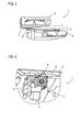
- adjusting device 1 comprises an actuator which is designed as a coupling mechanism, comprising a first drive 2 with a rotationally fixed lever 3, which is pivotally connected to a push rod 4.
- the adjusting device 1 comprises a second drive 5 with a rotationally fixed lever 6 which is pivotally connected to a push rod 7.
- Fig. 1 one recognizes that the two push rods 4, 7 have a common attachment point 8, to which they are connected to each other by means of a bolt.
- the two drives 2, 5 are constructed substantially identical.
- Each drive 2, 5 comprises an electric motor, which is associated with a reduction gear. Accordingly, the two are rotationally fixed with the respective drive connected lever 3, 6 rotated with respect to the engine speed reduced speed.
- Fig. 2 shows the adjusting device 1 from the opposite side, so that the drive 2 is located in front of the drive 5.
- the two drives 2, 5 are arranged slightly inclined to each other with respect to their longitudinal axes, which is due to the installation situation.
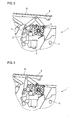
- Fig. 3 In the top view of Fig. 3 it can be seen that the two drives 2, 5 are arranged parallel to each other. Accordingly, the levers 3, 6 and the push rods 4, 7 are arranged parallel to each other. Thus, the two levers and the two push rods move substantially along a plane.
- the attachment point 8, which also serves as a connection to the front flap, can thus be moved by means of the adjusting device 1 along a plane.
- two such adjustment devices 1 are mounted on opposite sides in the engine compartment, such that the attachment points 8 of the two adjustment devices are located on opposite sides in the vicinity of the rear end of the front flap.
- Fig. 4 is a side view and shows the adjusting device 1, which is arranged in the engine compartment of a motor vehicle.
- the attachment point 8 or the existing at this point bolt is pivotally connected to a leg 9.
- the leg 9 essentially has a U-profile. When installed, the leg 9 is connected to the front flap 10, which in Fig. 4 is shown only schematically.
- the adjusting device 1 also includes a schematically illustrated control device 11, which is designed for the coordinated control of the two drives 2, 5. Due to the coupling of the two push rods 4, 7, it is necessary to control the drives 2, 5 coordinated to avoid constraining forces.
- Fig. 4 shows the adjusting device 1 in the normal position in which the front door 10 is closed.
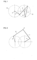
- Fig. 7 the corresponding kinematics is shown. In particular, one recognizes there the positions of the levers 3, 6 and the positions of the push rods 4, 7. Likewise, for each drive 2, 5 a circle 12, 13 is shown, which indicates the movement path of the rotatable levers 3, 6.
- Fig. 7 recognizes that in the initial position of the lever 3 and the push rod 4 of the drive 2 are arranged approximately at right angles to each other, whereas the lever 6 and the push rod 7 of the second drive 5 include an acute angle.
- Fig. 5 shows the adjusting device 1, after this from the in Fig. 4 shown position has been moved to the so-called pedestrian protection position.
- These are the levers 3, 6 in the view of Fig. 5 turned counterclockwise.
- the leg 9 and accordingly also the front flap 10 both vertically upwards and horizontally to the rear, ie in the view of Fig. 5 to the left, to be moved.
- this pedestrian protection position is below the front door 10, a free space that serves as a deformation space in a collision of a pedestrian, so that a large part of the kinetic energy can be absorbed by a deformation of the front door 10 so that less serious injuries to the pedestrian are to be expected ,
- Fig. 8 In the associated kinematic representation of Fig. 8 it can be seen that the lever 3 and the push rod 4, which acts like a connecting rod, form an angle which is slightly larger than a right angle. Similarly, the lever 6 with the push rod 7 forms approximately a right angle. It can also be seen that the two push rods 4, 7 which touch one another in the attachment point 8 also assume approximately a right angle to one another. While the control device 11 controls the two drives 2, 5, the front flap 10 can from the in Fig. 7 shown Starting position in less than half a second in the Fig. 8 shown pedestrian protection position to be moved.
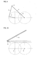
- Fig. 6 shows the adjusting device 1, after this starting from the retracted position, the in Fig. 4 is shown or starting from the in Fig. 5 shown pedestrian protection position has been moved to a so-called type damage position.
- this type damage position of the leg 9 is compared to the pedestrian protection position further to the rear, ie in the view of Fig. 6 moved to the left.
- the vertical position is essentially the same as in Fig. 5 shown pedestrian protection position. In this position, the front edge of the front flap 10 is moved even further back, so that the risk of damage is reduced.
- Fig. 9 In the associated kinematic representation of Fig. 9 it can be seen that the lever 6 and the push rod 7 are "stretched", ie the attachment point 8 is located at the farthest position of the axis of rotation, which is possible.
- the lever 3 and the push rod 4 form approximately a right angle with each other. If it has been detected by environmental sensors that an expected impact has failed, the front flap 10 can by means of the drives 2, 6 from the in Fig. 9 shown position backwards in the in Fig. 5 shown pedestrian protection position and continue in the in Fig. 4 shown starting position, which is controlled by the controller 11.
- Fig. 10 It is shown that the front flap 10 can be lifted by means of the drives 2, 5 and pushed into a front flap-side abutment 14.
- the front flap 10 by means of the drives 2, 5 both raised and to the rear, in the view of Fig. 10 to the left, moved.
- a lock of the front door 10 is released by the drives 2, 5, the front door 10 is then pivoted to the maintenance position shown in dashed lines. In this open position of the front door 10, the engine compartment is accessible for maintenance or repair work.
Applications Claiming Priority (1)
| Application Number | Priority Date | Filing Date | Title |
|---|---|---|---|
| DE201310017457 DE102013017457A1 (de) | 2013-10-21 | 2013-10-21 | Verstellvorrichtung für eine Frontklappe und zugehöriges Kraftfahrzeug |
Publications (2)
| Publication Number | Publication Date |
|---|---|
| EP2862756A1 true EP2862756A1 (fr) | 2015-04-22 |
| EP2862756B1 EP2862756B1 (fr) | 2016-08-17 |
Family
ID=51398477
Family Applications (1)
| Application Number | Title | Priority Date | Filing Date |
|---|---|---|---|
| EP14002921.6A Active EP2862756B1 (fr) | 2013-10-21 | 2014-08-22 | Dispositif de réglage d'un volet avant et véhicule automobile associé |
Country Status (4)
| Country | Link |
|---|---|
| US (1) | US9738246B2 (fr) |
| EP (1) | EP2862756B1 (fr) |
| CN (1) | CN104554128B (fr) |
| DE (1) | DE102013017457A1 (fr) |
Families Citing this family (4)
| Publication number | Priority date | Publication date | Assignee | Title |
|---|---|---|---|---|
| DE102013007594B4 (de) | 2013-05-02 | 2015-03-26 | Audi Ag | Vorrichtung zum Absorbieren von Bewegungsenergie, insbesondere zum Einbau in ein Kraftfahrzeug |
| DE102013017475A1 (de) * | 2013-10-21 | 2015-04-23 | Audi Ag | Verstellvorrichtung für eine Frontklappe |
| DE102013017456B4 (de) * | 2013-10-21 | 2018-07-12 | Audi Ag | Verstellvorrichtung für eine Frontklappe und zugehöriges Kraftfahrzeug |
| KR20200050144A (ko) * | 2018-11-01 | 2020-05-11 | 현대자동차주식회사 | Adas 연계 상시 작동 액티브 후드 장치 |
Citations (2)
| Publication number | Priority date | Publication date | Assignee | Title |
|---|---|---|---|---|
| DE20106478U1 (de) * | 2000-08-08 | 2001-10-11 | Trw Automotive Electron & Comp | Antrieb einer an einem Fahrzeug vorgesehenen Klappe und Fußgängerschutz an einem Kraftfahrzeug |
| JP2009090908A (ja) * | 2007-10-11 | 2009-04-30 | Toyota Central R&D Labs Inc | フード下降装置 |
Family Cites Families (25)
| Publication number | Priority date | Publication date | Assignee | Title |
|---|---|---|---|---|
| EP1258402B8 (fr) * | 2001-05-17 | 2006-06-28 | TRW Automotive Electronics & Components GmbH & Co. KG | Actionneur pour capot de véhicule |
| CN2512670Y (zh) * | 2001-09-29 | 2002-09-25 | 王德法 | 一种车位保护器 |
| DE10323118B4 (de) * | 2003-05-22 | 2011-07-21 | Bayerische Motoren Werke Aktiengesellschaft, 80809 | Einrichtung zum manuellen Reversieren einer Vorrichtung zum Schutz von Personen bei einem Frontalaufprall auf ein Kraftfahrzeug |
| DE10331047B4 (de) * | 2003-07-01 | 2015-10-01 | Witte-Velbert Gmbh & Co. Kg | Frontklappenanordnung an oder für ein Kraftfahrzeug |
| JP4453285B2 (ja) * | 2003-07-09 | 2010-04-21 | トヨタ自動車株式会社 | 衝突対象保護装置の制御装置 |
| JP4206895B2 (ja) * | 2003-10-15 | 2009-01-14 | 三菱自動車工業株式会社 | 車両用フード装置 |
| DE102005033609B4 (de) * | 2005-07-14 | 2013-02-07 | Webasto Ag | Antriebsvorrichtung eines bewegbaren Bauteils eines Fahrzeugs |
| CA2518682A1 (fr) * | 2005-09-09 | 2007-03-09 | Multimatic Inc. | Charniere de capot pour la protection des pietons |
| DE102006002827B3 (de) * | 2006-01-19 | 2007-09-06 | Magna Car Top Systems Gmbh | Mehrgelenkkinematik für Heckdeckel von Fahrzeugen mit offenem Aufbau |
| DE102006010801B4 (de) * | 2006-03-07 | 2021-05-20 | Magna Electronics Europe Gmbh & Co. Ohg | Anstellvorrichtung und Anstellverfahren für eine Motorhaube |
| DE102006034726A1 (de) * | 2006-07-27 | 2008-01-31 | Automotive Group Ise Innomotive Systems Europe Gmbh | Vorrichtung zum Aufstellen der Fronthaube eines Kraftfahrzeuges bei einem drohenden Personenaufprall |
| DE102006042498A1 (de) * | 2006-09-07 | 2008-03-27 | Suspa Holding Gmbh | Fußgänger-Schutz-Vorrichtung an einem Kraftfahrzeug |
| DE102008046145A1 (de) * | 2008-09-05 | 2010-03-11 | Bayerische Motoren Werke Aktiengesellschaft | Scharniereinrichtung für eine Frontklappe eines Kraftfahrzeugs mit einer Fußgängerschutzeinrichtung |
| FR2935732B1 (fr) * | 2008-09-11 | 2011-11-18 | Peugeot Citroen Automobiles Sa | Dispositif de securite pour le capot avant d'une automobile, notamment pour le cas d'un choc pieton. |
| DE102008058186A1 (de) * | 2008-11-20 | 2010-05-27 | Bayerische Motoren Werke Aktiengesellschaft | Scharniereinrichtung mit Fußgängerschutzeinrichtung für eine Frontklappe eines Kraftfahrzeugs |
| DE102009006451A1 (de) * | 2009-01-28 | 2010-07-29 | Bayerische Motoren Werke Aktiengesellschaft | Dämpfungseinrichtung an einer Frontklappe eines Kraftfahrzeugs |
| DE102009040417A1 (de) * | 2009-09-07 | 2011-03-10 | Bayerische Motoren Werke Aktiengesellschaft | Fahrzeug-Sicherheitseinrichtung mit einem schwenkbaren Scharnierteil |
| DE102010023971B3 (de) | 2010-06-16 | 2011-12-08 | Audi Ag | Verfahren zum Einbau einer Vorrichtung zum federunterstützten Verschwenken einer Klappe oder Tür in ein Fahrzeug |
| CN102582567B (zh) * | 2012-02-29 | 2014-04-02 | 华南理工大学 | 一种有利于行人保护的发动机罩弹起装置 |
| KR101491310B1 (ko) * | 2013-09-04 | 2015-02-06 | 현대자동차주식회사 | 차량용 후드 장치 |
| DE102013017475A1 (de) * | 2013-10-21 | 2015-04-23 | Audi Ag | Verstellvorrichtung für eine Frontklappe |
| KR101510011B1 (ko) * | 2013-12-17 | 2015-04-07 | 현대자동차주식회사 | 차량용 액티브 후드 힌지장치 |
| EP3178708B1 (fr) * | 2014-08-07 | 2019-05-22 | Toyota Jidosha Kabushiki Kaisha | Dispositif de capot à soulèvement automatique pour véhicule |
| DE102015109128B3 (de) * | 2015-04-10 | 2016-07-21 | KINEMATIXX GmbH | Frontklappenscharnier mit drehbeweglichem Entriegelungsmechanismus |
| DE102015010395B3 (de) * | 2015-08-10 | 2016-11-17 | Audi Ag | Frontklappenscharnier und zugehöriges Kraftfahrzeug |
-
2013
- 2013-10-21 DE DE201310017457 patent/DE102013017457A1/de not_active Withdrawn
-
2014
- 2014-08-22 EP EP14002921.6A patent/EP2862756B1/fr active Active
- 2014-10-20 US US14/518,236 patent/US9738246B2/en active Active
- 2014-10-21 CN CN201410562577.1A patent/CN104554128B/zh active Active
Patent Citations (2)
| Publication number | Priority date | Publication date | Assignee | Title |
|---|---|---|---|---|
| DE20106478U1 (de) * | 2000-08-08 | 2001-10-11 | Trw Automotive Electron & Comp | Antrieb einer an einem Fahrzeug vorgesehenen Klappe und Fußgängerschutz an einem Kraftfahrzeug |
| JP2009090908A (ja) * | 2007-10-11 | 2009-04-30 | Toyota Central R&D Labs Inc | フード下降装置 |
Also Published As
| Publication number | Publication date |
|---|---|
| US9738246B2 (en) | 2017-08-22 |
| CN104554128B (zh) | 2017-04-12 |
| CN104554128A (zh) | 2015-04-29 |
| DE102013017457A1 (de) | 2015-04-23 |
| EP2862756B1 (fr) | 2016-08-17 |
| US20150108770A1 (en) | 2015-04-23 |
Similar Documents
| Publication | Publication Date | Title |
|---|---|---|
| DE102006010801B4 (de) | Anstellvorrichtung und Anstellverfahren für eine Motorhaube | |
| EP2862756B1 (fr) | Dispositif de réglage d'un volet avant et véhicule automobile associé | |
| WO2015177148A1 (fr) | Dispositif de verrouillage pour portes louvoyantes-coulissantes de véhicules de transport public ; porte louvoyante-coulissante équipée d'un dispositif de verrouillage | |
| EP2862758B1 (fr) | Dispositif de réglage pour un volet avant | |
| EP0222160A2 (fr) | Mécanisme d'actionnement pour une porte de chargement de fret | |
| EP1197369B1 (fr) | Déflecteur d'air pour véhicule convertible | |
| AT511710B1 (de) | Vorrichtung zum anstellen einer motorhaube | |
| EP2862757B1 (fr) | Dispositif de réglage d'un volet avant et véhicule automobile associé | |
| DE202015007818U1 (de) | Aufhangungsanordnung für eine Fahrzeugtür eines Fahrzeugs, Fahrzeugtür welche mittels einer Aufhängungsanordnung an einem Fahrzeug aufgehängt ist sowie Fahrzeug mit einer Fahrzeugtür, die mit einer derartigen Aufhängungsanordnung am Fahrzeug aufgehängt ist | |
| EP1716013A1 (fr) | Dispositif pour actionner au moins un element exterieur pivotant d'un vehicule | |
| AT501549B1 (de) | Trittstufenantrieb | |
| DE102013017453B4 (de) | Verstellvorrichtung für eine Frontklappe und zugehöriges Kraftfahrzeug | |
| DE102016002522B3 (de) | Verstelleinrichtung für eine Frontklappe eines Kraftfahrszeugs und zugehöriges Kraftfahrzeugs | |
| EP1848603B1 (fr) | Toit rigide | |
| DE102013202801B4 (de) | Einrichtung zur motorischen Betätigung einer Kraftfahrzeug-Türe mit Feststellfunktion | |
| DE102013003137B4 (de) | Klappe für ein Kraftfahrzeug und zugehöriges Kraftfahrzeug | |
| DE102015203432B4 (de) | Scharniereinrichtung mit Aufstellhebel und Schwenkhebel für eine Frontklappe eines Kraftfahrzeuges | |
| DE102014013771B4 (de) | Verstelleinrichtung zum Anheben der Hinterkante einer Frontklappe eines Kraftfahrzeugs | |
| EP3183407B1 (fr) | Ensemble charnière pour porte de véhicule automobile | |
| AT517204B1 (de) | Sessel für einen Sessellift | |
| DE102013017454B4 (de) | Verstellvorrichtung für eine Frontklappe und zugehöriges Kraftfahrzeug | |
| DE102022124965B3 (de) | Antriebsvorrichtung für eine Fahrzeugklappe | |
| DE102015208399B4 (de) | Kraftfahrzeug mit einer Frontklappe | |
| DE102013017451B4 (de) | Verstelleinrichtung, Klappe mit einer Verstelleinrichtung und zugehöriges Kraftfahrzeug | |
| DE102020121341A1 (de) | Verdeckkastendeckelanordnung mit Lenkeranordnung und Verschlussanordnung |
Legal Events
| Date | Code | Title | Description |
|---|---|---|---|
| PUAI | Public reference made under article 153(3) epc to a published international application that has entered the european phase |
Free format text: ORIGINAL CODE: 0009012 |
|
| 17P | Request for examination filed |
Effective date: 20140822 |
|
| AK | Designated contracting states |
Kind code of ref document: A1 Designated state(s): AL AT BE BG CH CY CZ DE DK EE ES FI FR GB GR HR HU IE IS IT LI LT LU LV MC MK MT NL NO PL PT RO RS SE SI SK SM TR |
|
| AX | Request for extension of the european patent |
Extension state: BA ME |
|
| R17P | Request for examination filed (corrected) |
Effective date: 20151022 |
|
| RBV | Designated contracting states (corrected) |
Designated state(s): AL AT BE BG CH CY CZ DE DK EE ES FI FR GB GR HR HU IE IS IT LI LT LU LV MC MK MT NL NO PL PT RO RS SE SI SK SM TR |
|
| GRAP | Despatch of communication of intention to grant a patent |
Free format text: ORIGINAL CODE: EPIDOSNIGR1 |
|
| INTG | Intention to grant announced |
Effective date: 20160527 |
|
| GRAS | Grant fee paid |
Free format text: ORIGINAL CODE: EPIDOSNIGR3 |
|
| GRAA | (expected) grant |
Free format text: ORIGINAL CODE: 0009210 |
|
| AK | Designated contracting states |
Kind code of ref document: B1 Designated state(s): AL AT BE BG CH CY CZ DE DK EE ES FI FR GB GR HR HU IE IS IT LI LT LU LV MC MK MT NL NO PL PT RO RS SE SI SK SM TR |
|
| REG | Reference to a national code |
Ref country code: GB Ref legal event code: FG4D Free format text: NOT ENGLISH |
|
| REG | Reference to a national code |
Ref country code: CH Ref legal event code: EP Ref country code: FR Ref legal event code: PLFP Year of fee payment: 3 |
|
| REG | Reference to a national code |
Ref country code: IE Ref legal event code: FG4D Free format text: LANGUAGE OF EP DOCUMENT: GERMAN |
|
| REG | Reference to a national code |
Ref country code: AT Ref legal event code: REF Ref document number: 820722 Country of ref document: AT Kind code of ref document: T Effective date: 20160915 |
|
| REG | Reference to a national code |
Ref country code: DE Ref legal event code: R096 Ref document number: 502014001233 Country of ref document: DE |
|
| REG | Reference to a national code |
Ref country code: NL Ref legal event code: MP Effective date: 20160817 |
|
| REG | Reference to a national code |
Ref country code: LT Ref legal event code: MG4D |
|
| PG25 | Lapsed in a contracting state [announced via postgrant information from national office to epo] |
Ref country code: HR Free format text: LAPSE BECAUSE OF FAILURE TO SUBMIT A TRANSLATION OF THE DESCRIPTION OR TO PAY THE FEE WITHIN THE PRESCRIBED TIME-LIMIT Effective date: 20160817 Ref country code: NL Free format text: LAPSE BECAUSE OF FAILURE TO SUBMIT A TRANSLATION OF THE DESCRIPTION OR TO PAY THE FEE WITHIN THE PRESCRIBED TIME-LIMIT Effective date: 20160817 Ref country code: FI Free format text: LAPSE BECAUSE OF FAILURE TO SUBMIT A TRANSLATION OF THE DESCRIPTION OR TO PAY THE FEE WITHIN THE PRESCRIBED TIME-LIMIT Effective date: 20160817 Ref country code: NO Free format text: LAPSE BECAUSE OF FAILURE TO SUBMIT A TRANSLATION OF THE DESCRIPTION OR TO PAY THE FEE WITHIN THE PRESCRIBED TIME-LIMIT Effective date: 20161117 Ref country code: RS Free format text: LAPSE BECAUSE OF FAILURE TO SUBMIT A TRANSLATION OF THE DESCRIPTION OR TO PAY THE FEE WITHIN THE PRESCRIBED TIME-LIMIT Effective date: 20160817 Ref country code: IT Free format text: LAPSE BECAUSE OF FAILURE TO SUBMIT A TRANSLATION OF THE DESCRIPTION OR TO PAY THE FEE WITHIN THE PRESCRIBED TIME-LIMIT Effective date: 20160817 Ref country code: LT Free format text: LAPSE BECAUSE OF FAILURE TO SUBMIT A TRANSLATION OF THE DESCRIPTION OR TO PAY THE FEE WITHIN THE PRESCRIBED TIME-LIMIT Effective date: 20160817 |
|
| PG25 | Lapsed in a contracting state [announced via postgrant information from national office to epo] |
Ref country code: PT Free format text: LAPSE BECAUSE OF FAILURE TO SUBMIT A TRANSLATION OF THE DESCRIPTION OR TO PAY THE FEE WITHIN THE PRESCRIBED TIME-LIMIT Effective date: 20161219 Ref country code: ES Free format text: LAPSE BECAUSE OF FAILURE TO SUBMIT A TRANSLATION OF THE DESCRIPTION OR TO PAY THE FEE WITHIN THE PRESCRIBED TIME-LIMIT Effective date: 20160817 Ref country code: BE Free format text: LAPSE BECAUSE OF NON-PAYMENT OF DUE FEES Effective date: 20160831 Ref country code: PL Free format text: LAPSE BECAUSE OF FAILURE TO SUBMIT A TRANSLATION OF THE DESCRIPTION OR TO PAY THE FEE WITHIN THE PRESCRIBED TIME-LIMIT Effective date: 20160817 Ref country code: LV Free format text: LAPSE BECAUSE OF FAILURE TO SUBMIT A TRANSLATION OF THE DESCRIPTION OR TO PAY THE FEE WITHIN THE PRESCRIBED TIME-LIMIT Effective date: 20160817 Ref country code: GR Free format text: LAPSE BECAUSE OF FAILURE TO SUBMIT A TRANSLATION OF THE DESCRIPTION OR TO PAY THE FEE WITHIN THE PRESCRIBED TIME-LIMIT Effective date: 20161118 Ref country code: SE Free format text: LAPSE BECAUSE OF FAILURE TO SUBMIT A TRANSLATION OF THE DESCRIPTION OR TO PAY THE FEE WITHIN THE PRESCRIBED TIME-LIMIT Effective date: 20160817 |
|
| PG25 | Lapsed in a contracting state [announced via postgrant information from national office to epo] |
Ref country code: EE Free format text: LAPSE BECAUSE OF FAILURE TO SUBMIT A TRANSLATION OF THE DESCRIPTION OR TO PAY THE FEE WITHIN THE PRESCRIBED TIME-LIMIT Effective date: 20160817 Ref country code: RO Free format text: LAPSE BECAUSE OF FAILURE TO SUBMIT A TRANSLATION OF THE DESCRIPTION OR TO PAY THE FEE WITHIN THE PRESCRIBED TIME-LIMIT Effective date: 20160817 |
|
| REG | Reference to a national code |
Ref country code: DE Ref legal event code: R097 Ref document number: 502014001233 Country of ref document: DE |
|
| PG25 | Lapsed in a contracting state [announced via postgrant information from national office to epo] |
Ref country code: SM Free format text: LAPSE BECAUSE OF FAILURE TO SUBMIT A TRANSLATION OF THE DESCRIPTION OR TO PAY THE FEE WITHIN THE PRESCRIBED TIME-LIMIT Effective date: 20160817 Ref country code: SK Free format text: LAPSE BECAUSE OF FAILURE TO SUBMIT A TRANSLATION OF THE DESCRIPTION OR TO PAY THE FEE WITHIN THE PRESCRIBED TIME-LIMIT Effective date: 20160817 Ref country code: DK Free format text: LAPSE BECAUSE OF FAILURE TO SUBMIT A TRANSLATION OF THE DESCRIPTION OR TO PAY THE FEE WITHIN THE PRESCRIBED TIME-LIMIT Effective date: 20160817 Ref country code: CZ Free format text: LAPSE BECAUSE OF FAILURE TO SUBMIT A TRANSLATION OF THE DESCRIPTION OR TO PAY THE FEE WITHIN THE PRESCRIBED TIME-LIMIT Effective date: 20160817 Ref country code: BG Free format text: LAPSE BECAUSE OF FAILURE TO SUBMIT A TRANSLATION OF THE DESCRIPTION OR TO PAY THE FEE WITHIN THE PRESCRIBED TIME-LIMIT Effective date: 20161117 |
|
| REG | Reference to a national code |
Ref country code: IE Ref legal event code: MM4A |
|
| PLBE | No opposition filed within time limit |
Free format text: ORIGINAL CODE: 0009261 |
|
| STAA | Information on the status of an ep patent application or granted ep patent |
Free format text: STATUS: NO OPPOSITION FILED WITHIN TIME LIMIT |
|
| PG25 | Lapsed in a contracting state [announced via postgrant information from national office to epo] |
Ref country code: MC Free format text: LAPSE BECAUSE OF FAILURE TO SUBMIT A TRANSLATION OF THE DESCRIPTION OR TO PAY THE FEE WITHIN THE PRESCRIBED TIME-LIMIT Effective date: 20160817 |
|
| 26N | No opposition filed |
Effective date: 20170518 |
|
| PG25 | Lapsed in a contracting state [announced via postgrant information from national office to epo] |
Ref country code: IE Free format text: LAPSE BECAUSE OF NON-PAYMENT OF DUE FEES Effective date: 20160822 |
|
| REG | Reference to a national code |
Ref country code: FR Ref legal event code: PLFP Year of fee payment: 4 |
|
| PG25 | Lapsed in a contracting state [announced via postgrant information from national office to epo] |
Ref country code: SI Free format text: LAPSE BECAUSE OF FAILURE TO SUBMIT A TRANSLATION OF THE DESCRIPTION OR TO PAY THE FEE WITHIN THE PRESCRIBED TIME-LIMIT Effective date: 20160817 Ref country code: LU Free format text: LAPSE BECAUSE OF NON-PAYMENT OF DUE FEES Effective date: 20160822 |
|
| REG | Reference to a national code |
Ref country code: CH Ref legal event code: PL |
|
| PG25 | Lapsed in a contracting state [announced via postgrant information from national office to epo] |
Ref country code: LI Free format text: LAPSE BECAUSE OF NON-PAYMENT OF DUE FEES Effective date: 20170831 Ref country code: CH Free format text: LAPSE BECAUSE OF NON-PAYMENT OF DUE FEES Effective date: 20170831 |
|
| PG25 | Lapsed in a contracting state [announced via postgrant information from national office to epo] |
Ref country code: HU Free format text: LAPSE BECAUSE OF FAILURE TO SUBMIT A TRANSLATION OF THE DESCRIPTION OR TO PAY THE FEE WITHIN THE PRESCRIBED TIME-LIMIT; INVALID AB INITIO Effective date: 20140822 |
|
| PG25 | Lapsed in a contracting state [announced via postgrant information from national office to epo] |
Ref country code: MT Free format text: LAPSE BECAUSE OF FAILURE TO SUBMIT A TRANSLATION OF THE DESCRIPTION OR TO PAY THE FEE WITHIN THE PRESCRIBED TIME-LIMIT Effective date: 20160817 Ref country code: MK Free format text: LAPSE BECAUSE OF FAILURE TO SUBMIT A TRANSLATION OF THE DESCRIPTION OR TO PAY THE FEE WITHIN THE PRESCRIBED TIME-LIMIT Effective date: 20160817 Ref country code: IS Free format text: LAPSE BECAUSE OF FAILURE TO SUBMIT A TRANSLATION OF THE DESCRIPTION OR TO PAY THE FEE WITHIN THE PRESCRIBED TIME-LIMIT Effective date: 20160817 Ref country code: CY Free format text: LAPSE BECAUSE OF FAILURE TO SUBMIT A TRANSLATION OF THE DESCRIPTION OR TO PAY THE FEE WITHIN THE PRESCRIBED TIME-LIMIT Effective date: 20160817 |
|
| REG | Reference to a national code |
Ref country code: FR Ref legal event code: PLFP Year of fee payment: 5 |
|
| PG25 | Lapsed in a contracting state [announced via postgrant information from national office to epo] |
Ref country code: TR Free format text: LAPSE BECAUSE OF FAILURE TO SUBMIT A TRANSLATION OF THE DESCRIPTION OR TO PAY THE FEE WITHIN THE PRESCRIBED TIME-LIMIT Effective date: 20160817 Ref country code: AL Free format text: LAPSE BECAUSE OF FAILURE TO SUBMIT A TRANSLATION OF THE DESCRIPTION OR TO PAY THE FEE WITHIN THE PRESCRIBED TIME-LIMIT Effective date: 20160817 |
|
| REG | Reference to a national code |
Ref country code: AT Ref legal event code: MM01 Ref document number: 820722 Country of ref document: AT Kind code of ref document: T Effective date: 20190822 |
|
| PG25 | Lapsed in a contracting state [announced via postgrant information from national office to epo] |
Ref country code: AT Free format text: LAPSE BECAUSE OF NON-PAYMENT OF DUE FEES Effective date: 20190822 |
|
| P01 | Opt-out of the competence of the unified patent court (upc) registered |
Effective date: 20230530 |
|
| PGFP | Annual fee paid to national office [announced via postgrant information from national office to epo] |
Ref country code: GB Payment date: 20230824 Year of fee payment: 10 |
|
| PGFP | Annual fee paid to national office [announced via postgrant information from national office to epo] |
Ref country code: FR Payment date: 20230824 Year of fee payment: 10 Ref country code: DE Payment date: 20230831 Year of fee payment: 10 |