EP2862756A1 - Verstellvorrichtung für eine Frontklappe und zugehöriges Kraftfahrzeug - Google Patents
Verstellvorrichtung für eine Frontklappe und zugehöriges Kraftfahrzeug Download PDFInfo
- Publication number
- EP2862756A1 EP2862756A1 EP20140002921 EP14002921A EP2862756A1 EP 2862756 A1 EP2862756 A1 EP 2862756A1 EP 20140002921 EP20140002921 EP 20140002921 EP 14002921 A EP14002921 A EP 14002921A EP 2862756 A1 EP2862756 A1 EP 2862756A1
- Authority
- EP
- European Patent Office
- Prior art keywords
- adjusting device
- front flap
- drive
- designed
- control
- Prior art date
- Legal status (The legal status is an assumption and is not a legal conclusion. Google has not performed a legal analysis and makes no representation as to the accuracy of the status listed.)
- Granted
Links
Images

Classifications
-
- B—PERFORMING OPERATIONS; TRANSPORTING
- B60—VEHICLES IN GENERAL
- B60R—VEHICLES, VEHICLE FITTINGS, OR VEHICLE PARTS, NOT OTHERWISE PROVIDED FOR
- B60R21/00—Arrangements or fittings on vehicles for protecting or preventing injuries to occupants or pedestrians in case of accidents or other traffic risks
- B60R21/34—Protecting non-occupants of a vehicle, e.g. pedestrians
- B60R21/38—Protecting non-occupants of a vehicle, e.g. pedestrians using means for lifting bonnets
-
- Y—GENERAL TAGGING OF NEW TECHNOLOGICAL DEVELOPMENTS; GENERAL TAGGING OF CROSS-SECTIONAL TECHNOLOGIES SPANNING OVER SEVERAL SECTIONS OF THE IPC; TECHNICAL SUBJECTS COVERED BY FORMER USPC CROSS-REFERENCE ART COLLECTIONS [XRACs] AND DIGESTS
- Y10—TECHNICAL SUBJECTS COVERED BY FORMER USPC
- Y10T—TECHNICAL SUBJECTS COVERED BY FORMER US CLASSIFICATION
- Y10T292/00—Closure fasteners
- Y10T292/08—Bolts
- Y10T292/1043—Swinging
- Y10T292/1075—Operating means
- Y10T292/1082—Motor
Definitions
- the invention relates to an adjusting device for a front flap with an actuator for lifting the trailing edge of the front flap.
- a front door can be actively raised after the detection of an impact, so that a part of the impact energy can be absorbed by deformation of the front door.
- Such active front flaps are usually moved vertically upwards and also horizontally to the rear. In contrast, when the flap is not raised, there is usually no sufficient deformation space available due to the rigid substructure of the vehicle.
- the invention has for its object to provide an adjustment that offers advanced adjustment.
- the actuator is designed as a coupling mechanism, comprising a first drive with a non-rotatable lever which is pivotally connected to a push rod and a second drive with a non-rotatable lever with a push rod is pivotally connected, wherein the two push rods have a common attachment point, via which they are connected to the front door.
- the adjusting device thus comprises two separately controllable drives which are each connected to a multi-joint, wherein both joints are connected to each other and in addition to the front flap.
- the two drives are thus rotary actuators, through which the two levers and the two push rods can be moved coordinated, so that the desired positions of the front door can be approached.
- the first and second drive of the adjusting device according to the invention comprise an electric motor, wherein a reduction gear is preferably associated in the electric motor.
- a reduction gear is preferably associated in the electric motor.
- the common attachment point of the two push rods is connected to a leg attachable or attached to the front flap. Accordingly, the common attachment point of the two push rods has a bearing point on the leg, which in turn can be fastened or attached to the front flap.
- the adjusting device according to the invention may be formed as a modular, preassembled module that can be easily mounted in the engine compartment of a motor vehicle.
- the adjustment device according to the invention has or can be connected or connected to a control device which is designed to coordinate control of the first and the second drive. Due to the kinematic coupling of the two drives, it is important that both drives are controlled synchronously in order to avoid constraining forces.
- control device of the adjustment device according to the invention is designed to control the drives so that the front flap in a raised and horizontally to the rear shifted pedestrian protection position or in a further increased and further shifted back to the type damage position is movable.
- a free space is created below the front flap, which is available in a collision of a pedestrian as a deformation space available. Accordingly, an impact of a pedestrian, in particular a collision of the head, on a hard structure can be avoided in this way. Accordingly, the danger of serious injuries can be significantly reduced by means of the adjusting device according to the invention.
- the front flap In the so-called type damage position, the front flap is raised even further and moved to the rear, in the direction of the rear of the vehicle. If the front door is in the type damage position, the risk of damaging the front door is lowered.
- control device is designed to control the drives so that the front door is movable into a maintenance position in which the rear end of the front door is supported in a body-mounted abutment.
- a pivoting of the front flap in the maintenance position can be carried out without the need for additional components.
- the invention relates to a motor vehicle.
- the motor vehicle according to the invention is characterized in that it has at least one adjusting device, preferably two adjusting devices arranged on opposite sides of the engine compartment.
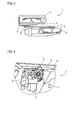
- adjusting device 1 comprises an actuator which is designed as a coupling mechanism, comprising a first drive 2 with a rotationally fixed lever 3, which is pivotally connected to a push rod 4.
- the adjusting device 1 comprises a second drive 5 with a rotationally fixed lever 6 which is pivotally connected to a push rod 7.
- Fig. 1 one recognizes that the two push rods 4, 7 have a common attachment point 8, to which they are connected to each other by means of a bolt.
- the two drives 2, 5 are constructed substantially identical.
- Each drive 2, 5 comprises an electric motor, which is associated with a reduction gear. Accordingly, the two are rotationally fixed with the respective drive connected lever 3, 6 rotated with respect to the engine speed reduced speed.
- Fig. 2 shows the adjusting device 1 from the opposite side, so that the drive 2 is located in front of the drive 5.
- the two drives 2, 5 are arranged slightly inclined to each other with respect to their longitudinal axes, which is due to the installation situation.
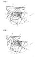
- Fig. 3 In the top view of Fig. 3 it can be seen that the two drives 2, 5 are arranged parallel to each other. Accordingly, the levers 3, 6 and the push rods 4, 7 are arranged parallel to each other. Thus, the two levers and the two push rods move substantially along a plane.
- the attachment point 8, which also serves as a connection to the front flap, can thus be moved by means of the adjusting device 1 along a plane.
- two such adjustment devices 1 are mounted on opposite sides in the engine compartment, such that the attachment points 8 of the two adjustment devices are located on opposite sides in the vicinity of the rear end of the front flap.
- Fig. 4 is a side view and shows the adjusting device 1, which is arranged in the engine compartment of a motor vehicle.
- the attachment point 8 or the existing at this point bolt is pivotally connected to a leg 9.
- the leg 9 essentially has a U-profile. When installed, the leg 9 is connected to the front flap 10, which in Fig. 4 is shown only schematically.
- the adjusting device 1 also includes a schematically illustrated control device 11, which is designed for the coordinated control of the two drives 2, 5. Due to the coupling of the two push rods 4, 7, it is necessary to control the drives 2, 5 coordinated to avoid constraining forces.
- Fig. 4 shows the adjusting device 1 in the normal position in which the front door 10 is closed.
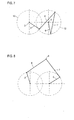
- Fig. 7 the corresponding kinematics is shown. In particular, one recognizes there the positions of the levers 3, 6 and the positions of the push rods 4, 7. Likewise, for each drive 2, 5 a circle 12, 13 is shown, which indicates the movement path of the rotatable levers 3, 6.
- Fig. 7 recognizes that in the initial position of the lever 3 and the push rod 4 of the drive 2 are arranged approximately at right angles to each other, whereas the lever 6 and the push rod 7 of the second drive 5 include an acute angle.
- Fig. 5 shows the adjusting device 1, after this from the in Fig. 4 shown position has been moved to the so-called pedestrian protection position.
- These are the levers 3, 6 in the view of Fig. 5 turned counterclockwise.
- the leg 9 and accordingly also the front flap 10 both vertically upwards and horizontally to the rear, ie in the view of Fig. 5 to the left, to be moved.
- this pedestrian protection position is below the front door 10, a free space that serves as a deformation space in a collision of a pedestrian, so that a large part of the kinetic energy can be absorbed by a deformation of the front door 10 so that less serious injuries to the pedestrian are to be expected ,
- Fig. 8 In the associated kinematic representation of Fig. 8 it can be seen that the lever 3 and the push rod 4, which acts like a connecting rod, form an angle which is slightly larger than a right angle. Similarly, the lever 6 with the push rod 7 forms approximately a right angle. It can also be seen that the two push rods 4, 7 which touch one another in the attachment point 8 also assume approximately a right angle to one another. While the control device 11 controls the two drives 2, 5, the front flap 10 can from the in Fig. 7 shown Starting position in less than half a second in the Fig. 8 shown pedestrian protection position to be moved.
- Fig. 6 shows the adjusting device 1, after this starting from the retracted position, the in Fig. 4 is shown or starting from the in Fig. 5 shown pedestrian protection position has been moved to a so-called type damage position.
- this type damage position of the leg 9 is compared to the pedestrian protection position further to the rear, ie in the view of Fig. 6 moved to the left.
- the vertical position is essentially the same as in Fig. 5 shown pedestrian protection position. In this position, the front edge of the front flap 10 is moved even further back, so that the risk of damage is reduced.
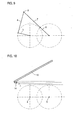
- Fig. 9 In the associated kinematic representation of Fig. 9 it can be seen that the lever 6 and the push rod 7 are "stretched", ie the attachment point 8 is located at the farthest position of the axis of rotation, which is possible.
- the lever 3 and the push rod 4 form approximately a right angle with each other. If it has been detected by environmental sensors that an expected impact has failed, the front flap 10 can by means of the drives 2, 6 from the in Fig. 9 shown position backwards in the in Fig. 5 shown pedestrian protection position and continue in the in Fig. 4 shown starting position, which is controlled by the controller 11.
- Fig. 10 It is shown that the front flap 10 can be lifted by means of the drives 2, 5 and pushed into a front flap-side abutment 14.
- the front flap 10 by means of the drives 2, 5 both raised and to the rear, in the view of Fig. 10 to the left, moved.
- a lock of the front door 10 is released by the drives 2, 5, the front door 10 is then pivoted to the maintenance position shown in dashed lines. In this open position of the front door 10, the engine compartment is accessible for maintenance or repair work.
Landscapes
- Engineering & Computer Science (AREA)
- Mechanical Engineering (AREA)
- Power-Operated Mechanisms For Wings (AREA)
- Body Structure For Vehicles (AREA)
- Superstructure Of Vehicle (AREA)
Abstract
Description
- Die Erfindung betrifft eine Verstellvorrichtung für eine Frontklappe mit einem Aktuator zum Anheben der Hinterkante der Frontklappe.
- Es ist bereits bekannt, bei Frontklappen von Kraftfahrzeugen einen Antrieb vorzusehen, um die Frontklappe in bestimmten Situationen verstellen zu können. Zum Schutz von Fußgängern kann eine Frontklappe nach der Detektion eines Aufpralls aktiv angehoben werden, damit ein Teil der Aufprallenergie durch Deformation der Frontklappe aufgenommen werden kann. Derartige aktive Frontklappen werden zumeist vertikal nach oben und zusätzlich horizontal nach hinten verschoben. Wenn die Klappe hingegen nicht angehoben wird, steht wegen der steifen Unterstruktur des Fahrzeugs zumeist kein ausreichender Verformungsraum zur Verfügung.
- Der Erfindung liegt die Aufgabe zugrunde, eine Verstellvorrichtung anzugeben, die erweiterte Verstellmöglichkeiten bietet.
- Zur Lösung dieser Aufgabe ist bei einer Verstellvorrichtung der eingangs genannten Art erfindungsgemäß vorgesehen, dass der Aktuator als Koppelgetriebe ausgebildet ist, umfassend einen ersten Antrieb mit einem drehfesten Hebel, der mit einer Schubstange gelenkig verbunden ist und einen zweiten Antrieb mit einem drehfesten Hebel, der mit einer Schubstange gelenkig verbunden ist, wobei die beiden Schubstangen einen gemeinsamen Befestigungspunkt besitzen, über den sie mit der Frontklappe verbunden sind.
- Die erfindungsgemäße Verstellvorrichtung umfasst somit zwei separat ansteuerbare Antriebe, die jeweils an ein Mehrgelenk angebunden sind, wobei beide Gelenke miteinander und zusätzlich mit der Frontklappe verbunden sind. Auf diese Weise wird eine Kinematik gebildet, die die für die gewünschte Verstellung der Frontklappe benötigten Verstellmöglichkeiten bietet. Bei den beiden Antrieben handelt es sich somit um Drehantriebe, durch die die beiden Hebel und die beiden Schubstangen koordiniert bewegt werden können, so dass die gewünschten Positionen der Frontklappe angefahren werden können.
- Vorzugsweise umfassen der erste und zweite Antrieb der erfindungsgemäßen Verstellvorrichtung einen Elektromotor, wobei im Elektromotor vorzugsweise ein Untersetzungsgetriebe zugeordnet ist. Durch die Wahl einer ausreichend hohen Drehzahl kann eine Verstellung der Frontklappe mittels der erfindungsgemäßen Verstellvorrichtung in einem äußerst kurzen Zeitraum erfolgen. Typischerweise wird für das Anfahren einer bestimmten Position lediglich ein Bruchteil einer Sekunde benötigt.
- Bei der erfindungsgemäßen Verstellvorrichtung kann es vorgesehen sein, dass der gemeinsame Befestigungspunkt der beiden Schubstangen mit einem an der Frontklappe anbringbaren oder angebrachten Schenkel verbunden ist. Dementsprechend besitzt der gemeinsame Befestigungspunkt der beiden Schubstangen eine Lagerstelle an dem Schenkel, der wiederum an der Frontklappe befestigbar oder befestigt ist. Auf diese Weise kann die erfindungsgemäße Verstellvorrichtung als modulare, vormontierte Baugruppe ausgebildet sein, die einfach im Motorraum eines Kraftfahrzeugs montiert werden kann.
- Es liegt auch im Rahmen der Erfindung, dass die erfindungsgemäße Verstellvorrichtung eine Steuerungseinrichtung aufweist oder damit verbindbar oder verbunden ist, die zum koordinierten Steuern des ersten und des zweiten Antriebs ausgebildet ist. Aufgrund der kinematischen Kopplung der beiden Antriebe ist es wichtig, dass beide Antriebe synchron gesteuert werden, um Zwangskräfte zu vermeiden.
- Es liegt auch im Rahmen der Erfindung, dass die Steuerungseinrichtung der erfindungsgemäßen Verstellvorrichtung dazu ausgebildet ist, die Antriebe so anzusteuern, dass die Frontklappe in eine erhöhte und horizontal nach hinten verschobene Fußgängerschutzstellung oder in eine weiter erhöhte und weiter nach hinten verschobene Typschadenstellung bewegbar ist. Durch das Bewegen der Frontklappe in die Fußgängerschutzstellung wird unterhalb der Frontklappe ein Freiraum geschaffen, der bei einem Aufprall eines Fußgängers als Verformungsraum zur Verfügung steht. Dementsprechend kann auf diese Weise ein Aufprall eines Fußgängers, insbesondere ein Aufprall des Kopfes, auf eine harte Struktur vermieden werden. Dementsprechend kann mittels der erfindungsgemäßen Verstellvorrichtung die Gefahr schwerer Verletzungen signifikant verringert werden.
- In der sogenannten Typschadenstellung ist die Frontklappe noch weiter angehoben und nach hinten, in Richtung zum Fahrzeugheck, verschoben. Wenn sich die Frontklappe in der Typschadenstellung befindet, wird die Gefahr von Beschädigungen der Frontklappe gesenkt.
- In weiterer Ausgestaltung der Erfindung kann es vorgesehen sein, dass die Steuerungseinrichtung dazu ausgebildet ist, die Antriebe so anzusteuern, dass die Frontklappe in eine Wartungsstellung bewegbar ist, in der das hintere Ende der Frontklappe in einem karosseriefesten Widerlager abgestützt ist. Bei dieser Ausgestaltung kann mittels der erfindungsgemäßen Verstellvorrichtung ein Schwenken der Frontklappe in die Wartungsstellung erfolgen, ohne dass dazu weitere Komponenten benötigt werden.
- Daneben betrifft die Erfindung ein Kraftfahrzeug. Das erfindungsgemäße Kraftfahrzeug zeichnet sich dadurch aus, dass es wenigstens eine Verstellvorrichtung, vorzugsweise zwei an gegenüberliegenden Seiten des Motorraums angeordnete Verstellvorrichtungen aufweist.
- Weitere Vorteile und Einzelheiten der Erfindung werden nachfolgend anhand eines Ausführungsbeispiels unter Bezugnahme auf die Zeichnungen erläutert. Die Zeichnungen sind schematische Darstellungen und zeigen:
- Fig. 1
- eine perspektivische Ansicht eines Ausführungsbeispiels einer erfindungsgemäßen Verstellvorrichtung,
- Fig. 2
- die Rückseite der in
Fig. 1 gezeigten Verstellvorrichtung, - Fig. 3
- eine Ansicht der Verstellvorrichtung von
Fig. 1 von oben, - Fig. 4
- die in einem Kraftfahrzeug angebrachte Verstellvorrichtung in eingefahrener Stellung,
- Fig. 5
- die Verstellvorrichtung in der Fußgängerschutzstellung,
- Fig. 6
- die Verstellvorrichtung in der Typschadenstellung,
- Fig. 7
- eine Darstellung der Kinematik in der eingefahrenen Stellung,
- Fig. 8
- eine Darstellung der Kinematik in der Fußgängerschutzstellung,
- Fig. 9
- eine Darstellung der Kinematik in der Typschadenstellung, und
- Fig. 10
- eine Darstellung der Kinematik, wenn sich die Frontklappe in einer Wartungsstellung befindet.
- Die in
Fig. 1 in einer perspektivischen Ansicht gezeigte Verstellvorrichtung 1 umfasst einen Aktuator, der als Koppelgetriebe ausgebildet ist, umfassend einen ersten Antrieb 2 mit einem drehfesten Hebel 3, der mit einer Schubstange 4 gelenkig verbunden ist. Daneben umfasst die Verstellvorrichtung 1 einen zweiten Antrieb 5 mit einem drehfesten Hebel 6, der mit einer Schubstange 7 gelenkig verbunden ist. - In
Fig. 1 erkennt man, dass die beiden Schubstangen 4, 7 einen gemeinsamen Befestigungspunkt 8 besitzen, an dem sie mittels eines Bolzens miteinander verbunden sind. In dem dargestellten Ausführungsbeispiel sind die beiden Antriebe 2, 5 im Wesentlichen identisch aufgebaut. Jeder Antrieb 2, 5 umfasst einen Elektromotor, dem ein Untersetzungsgetriebe zugeordnet ist. Dementsprechend werden die beiden drehfest mit dem jeweiligen Antrieb verbundenen Hebel 3, 6 mit einer gegenüber der Motordrehzahl reduzierten Drehzahl gedreht. -
Fig. 2 zeigt die Verstellvorrichtung 1 von der entgegengesetzten Seite, so dass sich der Antrieb 2 vor dem Antrieb 5 befindet. Die beiden Antriebe 2, 5 sind bezüglich ihrer Längsachsen leicht zueinander geneigt angeordnet, was durch die Einbausituation bedingt ist. - In der Draufsicht von
Fig. 3 erkennt man, dass die beiden Antriebe 2, 5 parallel zueinander angeordnet sind. Dementsprechend sind auch die Hebel 3, 6 und die Schubstangen 4, 7 parallel zueinander angeordnet. Somit bewegen sich die beiden Hebel und die beiden Schubstangen im Wesentlichen entlang einer Ebene. Der Befestigungspunkt 8, der gleichzeitig als Verbindung zur Frontklappe dient, kann somit mittels der Verstellvorrichtung 1 entlang einer Ebene bewegt werden. In einem Kraftfahrzeug werden zwei derartige Verstellvorrichtungen 1 an gegenüberliegenden Seiten im Motorraum montiert, derart, dass sich die Befestigungspunkte 8 der beiden Verstellvorrichtungen an gegenüberliegenden Seiten in der Nähe des hinteren Endes der Frontklappe befinden. -
Fig. 4 ist eine Seitenansicht und zeigt die Verstellvorrichtung 1, die im Motorraum eines Kraftfahrzeugs angeordnet ist. In der Zeichnung erkennt man, dass der Befestigungspunkt 8 bzw. der an dieser Stelle vorhandene Bolzen, gelenkig mit einem Schenkel 9 verbunden ist. Der Schenkel 9 weist im Wesentlichen ein U-Profil auf. Im eingebauten Zustand ist der Schenkel 9 mit der Frontklappe 10 verbunden, die inFig. 4 lediglich schematisch dargestellt ist. - Die Verstellvorrichtung 1 umfasst auch eine schematisch dargestellte Steuerungseinrichtung 11, die zum koordinierten Steuern der beiden Antriebe 2, 5 ausgebildet ist. Bedingt durch die Kopplung der beiden Schubstangen 4, 7 ist es erforderlich, die Antriebe 2, 5 koordiniert zu steuern, um Zwangskräfte zu vermeiden.
-
Fig. 4 zeigt die Verstellvorrichtung 1 in der normalen Position, in der die Frontklappe 10 geschlossen ist. - In
Fig. 7 ist die entsprechende Kinematik dargestellt. Insbesondere erkennt man dort die Positionen der Hebel 3, 6 sowie die Positionen der Schubstangen 4, 7. Ebenso ist für jeden Antrieb 2, 5 ein Kreis 12, 13 dargestellt, der die Bewegungsbahn der drehbaren Hebel 3, 6 angibt. - In
Fig. 7 erkennt man, dass in der Ausgangsstellung der Hebel 3 und die Schubstange 4 des Antriebs 2 näherungsweise rechtwinklig zueinander angeordnet sind, wohingegen der Hebel 6 und die Schubstange 7 des zweiten Antriebs 5 einen spitzen Winkel einschließen. -
Fig. 5 zeigt die Verstellvorrichtung 1, nachdem diese aus der inFig. 4 gezeigten Position in die sogenannte Fußgängerschutzstellung bewegt worden ist. Dazu sind die Hebel 3, 6 in der Ansicht vonFig. 5 gegen den Uhrzeigersinn gedreht worden. Dadurch ist der Schenkel 9 und dementsprechend auch die Frontklappe 10 sowohl vertikal nach oben als auch horizontal nach hinten, d. h. in der Ansicht vonFig. 5 nach links, verschoben werden. In dieser Fußgängerschutzstellung befindet sich unterhalb der Frontklappe 10 ein Freiraum, der bei einem Aufprall eines Fußgängers als Verformungsraum dient, so dass ein großer Teil der kinetischen Energie durch eine Verformung der Frontklappe 10 aufgenommen werden kann, so dass weniger schwerwiegende Verletzungen des Fußgängers zu erwarten sind. - In der zugehörigen kinematischen Darstellung von
Fig. 8 erkennt man, dass der Hebel 3 und die Schubstange 4, die wie ein Pleuel wirkt, einen Winkel bilden, der etwas größer als ein rechter Winkel ist. In ähnlicher Weise bildet auch der Hebel 6 mit der Schubstange 7 näherungsweise einen rechten Winkel. Man erkennt zudem, dass auch die beiden sich im Befestigungspunkt 8 berührenden Schubstangen 4, 7 näherungsweise einen rechten Winkel zueinander einnehmen. Während die Steuerungseinrichtung 11 die beiden Antriebe 2, 5 ansteuert, kann die Frontklappe 10 aus der inFig. 7 gezeigten Ausgangsstellung in weniger als einer halben Sekunde in die inFig. 8 gezeigte Fußgängerschutzstellung bewegt werden. -
Fig. 6 zeigt die Verstellvorrichtung 1, nachdem diese ausgehend von der eingefahrenen Stellung, die inFig. 4 gezeigt ist oder ausgehend von der inFig. 5 gezeigten Fußgängerschutzstellung in eine sogenannte Typschadenstellung bewegt worden ist. In dieser Typschadenstellung ist der Schenkel 9 im Vergleich zu der Fußgängerschutzstellung weiter nach hinten, d. h. in der Ansicht vonFig. 6 nach links verschoben. Die vertikale Position entspricht im Wesentlichen derjenigen der inFig. 5 gezeigten Fußgängerschutzstellung. In dieser Position ist die vordere Kante der Frontklappe 10 noch weiter nach hinten verschoben, so dass die Gefahr von Beschädigungen verringert ist. - In der zugehörigen kinematischen Darstellung von
Fig. 9 erkennt man, dass der Hebel 6 und die Schubstange 7 "gestreckt" sind, d. h. der Befestigungspunkt 8 befindet sich an der am weitesten entfernten Position von der Drehachse, die möglich ist. Der Hebel 3 und die Schubstange 4 bilden näherungsweise einen rechten Winkel miteinander. Falls von Umfeldsensoren detektiert worden ist, dass ein erwarteter Aufprall ausgeblieben ist, kann die Frontklappe 10 mittels der Antriebe 2, 6 aus der inFig. 9 gezeigten Position wieder rückwärts in die inFig. 5 gezeigte Fußgängerschutzstellung und weiter in die inFig. 4 gezeigte Ausgangsstellung bewegt werden, was durch die Steuerungseinrichtung 11 gesteuert wird. - In
Fig. 10 ist dargestellt, dass die Frontklappe 10 mittels der Antriebe 2, 5 angehoben und in ein frontklappenseitiges Widerlager 14 geschoben werden kann. Dazu wird die Frontklappe 10 mittels der Antriebe 2, 5 sowohl angehoben als auch nach hinten, in der Ansicht vonFig. 10 nach links, verschoben. Nach dem Erreichen dieser Schwenkposition wird ein Schloss der Frontklappe 10 freigegeben, durch die Antriebe 2, 5 wird die Frontklappe 10 dann in die gestrichelt dargestellte Wartungsstellung geschwenkt. In dieser geöffneten Stellung der Frontklappe 10 ist der Motorraum für Wartungs- oder Reparaturarbeiten zugänglich.
Claims (7)
- Verstellvorrichtung (1) für eine Frontklappe (10) mit einem Aktuator zum Anheben der Hinterkante der Frontklappe (10),
dadurch gekennzeichnet,
dass der Aktuator als Koppelgetriebe ausgebildet ist, umfassend einen ersten Antrieb (2) mit einem drehfesten Hebel (3), der mit einer Schubstange (4) gelenkig verbunden ist und einen zweiten Antrieb (5) mit einem drehfesten Hebel (3), der mit einer Schubstange (7) gelenkig verbunden ist, wobei die beiden Schubstangen (4, 7) einen gemeinsamen Befestigungspunkt (8) besitzen, über den sie mit der Frontklappe (10) verbunden sind. - Verstellvorrichtung nach Anspruch 1,
dadurch gekennzeichnet,
dass der erste und der zweite Antrieb (2, 5) einen Elektromotor umfassen, wobei einem Elektromotor vorzugsweise ein Untersetzungsgetriebe zugeordnet ist. - Verstellvorrichtung nach Anspruch 1 oder 2,
dadurch gekennzeichnet,
dass der gemeinsame Befestigungspunkt (8) der beiden Schubstangen (4, 7) mit einem an der Frontklappe (10) anbringbaren oder angebrachten, vorzugsweise als U-Profil ausgebildeten, Schenkel (9) verbunden ist. - Verstellvorrichtung nach einem der vorangehenden Ansprüche,
dadurch gekennzeichnet,
dass sie eine Steuerungseinrichtung (11) aufweist oder damit verbindbar oder verbunden ist, die zum koordinierten Steuern des ersten und des zweiten Antriebs (2, 5) ausgebildet ist. - Verstellvorrichtung nach Anspruch 4,
dadurch gekennzeichnet,
dass die Steuerungseinrichtung (11) dazu ausgebildet ist, die Antriebe (2, 5) so anzusteuern, dass die Frontklappe (10) in eine erhöhte und horizontal nach hinten verschobene Fußgängerschutzstellung oder in eine weiter erhöhte und weiter nach hinten verschobene Typschadenstellung bewegbar ist. - Verstellvorrichtung nach Anspruch 4 oder 5,
dadurch gekennzeichnet,
dass die Steuerungseinrichtung (11) dazu ausgebildet ist, die Antriebe (2, 5) so anzusteuern, dass die Frontklappe (10) in eine Wartungsstellung bewegbar ist, in der das hintere Ende der Frontklappe (10) in einem karosseriefesten Widerlager (14) abgestützt ist. - Kraftfahrzeug,
dadurch gekennzeichnet,
dass es wenigstens eine Verstellvorrichtung (1), vorzugsweise zwei an gegenüberliegenden Seiten des Motorraums angeordnete Verstellvorrichtungen (1) aufweist.
Applications Claiming Priority (1)
| Application Number | Priority Date | Filing Date | Title |
|---|---|---|---|
| DE201310017457 DE102013017457A1 (de) | 2013-10-21 | 2013-10-21 | Verstellvorrichtung für eine Frontklappe und zugehöriges Kraftfahrzeug |
Publications (2)
| Publication Number | Publication Date |
|---|---|
| EP2862756A1 true EP2862756A1 (de) | 2015-04-22 |
| EP2862756B1 EP2862756B1 (de) | 2016-08-17 |
Family
ID=51398477
Family Applications (1)
| Application Number | Title | Priority Date | Filing Date |
|---|---|---|---|
| EP14002921.6A Active EP2862756B1 (de) | 2013-10-21 | 2014-08-22 | Verstellvorrichtung für eine Frontklappe und zugehöriges Kraftfahrzeug |
Country Status (4)
| Country | Link |
|---|---|
| US (1) | US9738246B2 (de) |
| EP (1) | EP2862756B1 (de) |
| CN (1) | CN104554128B (de) |
| DE (1) | DE102013017457A1 (de) |
Families Citing this family (5)
| Publication number | Priority date | Publication date | Assignee | Title |
|---|---|---|---|---|
| DE102013007594B4 (de) | 2013-05-02 | 2015-03-26 | Audi Ag | Vorrichtung zum Absorbieren von Bewegungsenergie, insbesondere zum Einbau in ein Kraftfahrzeug |
| DE102013017475A1 (de) * | 2013-10-21 | 2015-04-23 | Audi Ag | Verstellvorrichtung für eine Frontklappe |
| DE102013017456B4 (de) * | 2013-10-21 | 2018-07-12 | Audi Ag | Verstellvorrichtung für eine Frontklappe und zugehöriges Kraftfahrzeug |
| KR102673002B1 (ko) * | 2018-11-01 | 2024-06-05 | 현대자동차주식회사 | Adas 연계 상시 작동 액티브 후드 장치 |
| DE102023111012A1 (de) | 2022-05-03 | 2023-11-09 | Magna Closures Inc. | Aktuatorsystem für eine verschlussplatte mit einem aufstellbaren sicherheitssystem für scharniere |
Citations (2)
| Publication number | Priority date | Publication date | Assignee | Title |
|---|---|---|---|---|
| DE20106478U1 (de) * | 2000-08-08 | 2001-10-11 | TRW Automotive Electronics & Components GmbH & Co. KG, 78315 Radolfzell | Antrieb einer an einem Fahrzeug vorgesehenen Klappe und Fußgängerschutz an einem Kraftfahrzeug |
| JP2009090908A (ja) * | 2007-10-11 | 2009-04-30 | Toyota Central R&D Labs Inc | フード下降装置 |
Family Cites Families (25)
| Publication number | Priority date | Publication date | Assignee | Title |
|---|---|---|---|---|
| EP1258402B8 (de) * | 2001-05-17 | 2006-06-28 | TRW Automotive Electronics & Components GmbH & Co. KG | Antrieb für Fahrzeughaube |
| CN2512670Y (zh) * | 2001-09-29 | 2002-09-25 | 王德法 | 一种车位保护器 |
| DE10323118B4 (de) * | 2003-05-22 | 2011-07-21 | Bayerische Motoren Werke Aktiengesellschaft, 80809 | Einrichtung zum manuellen Reversieren einer Vorrichtung zum Schutz von Personen bei einem Frontalaufprall auf ein Kraftfahrzeug |
| DE10331047B4 (de) * | 2003-07-01 | 2015-10-01 | Witte-Velbert Gmbh & Co. Kg | Frontklappenanordnung an oder für ein Kraftfahrzeug |
| JP4453285B2 (ja) * | 2003-07-09 | 2010-04-21 | トヨタ自動車株式会社 | 衝突対象保護装置の制御装置 |
| JP4206895B2 (ja) * | 2003-10-15 | 2009-01-14 | 三菱自動車工業株式会社 | 車両用フード装置 |
| DE102005033609B4 (de) * | 2005-07-14 | 2013-02-07 | Webasto Ag | Antriebsvorrichtung eines bewegbaren Bauteils eines Fahrzeugs |
| CA2518682A1 (en) * | 2005-09-09 | 2007-03-09 | Multimatic Inc. | Pedestrian protection hood hinge |
| DE102006002827B3 (de) * | 2006-01-19 | 2007-09-06 | Magna Car Top Systems Gmbh | Mehrgelenkkinematik für Heckdeckel von Fahrzeugen mit offenem Aufbau |
| DE102006010801B4 (de) * | 2006-03-07 | 2021-05-20 | Magna Electronics Europe Gmbh & Co. Ohg | Anstellvorrichtung und Anstellverfahren für eine Motorhaube |
| DE102006034726A1 (de) * | 2006-07-27 | 2008-01-31 | Automotive Group Ise Innomotive Systems Europe Gmbh | Vorrichtung zum Aufstellen der Fronthaube eines Kraftfahrzeuges bei einem drohenden Personenaufprall |
| DE102006042498A1 (de) * | 2006-09-07 | 2008-03-27 | Suspa Holding Gmbh | Fußgänger-Schutz-Vorrichtung an einem Kraftfahrzeug |
| DE102008046145A1 (de) * | 2008-09-05 | 2010-03-11 | Bayerische Motoren Werke Aktiengesellschaft | Scharniereinrichtung für eine Frontklappe eines Kraftfahrzeugs mit einer Fußgängerschutzeinrichtung |
| FR2935732B1 (fr) * | 2008-09-11 | 2011-11-18 | Peugeot Citroen Automobiles Sa | Dispositif de securite pour le capot avant d'une automobile, notamment pour le cas d'un choc pieton. |
| DE102008058186A1 (de) * | 2008-11-20 | 2010-05-27 | Bayerische Motoren Werke Aktiengesellschaft | Scharniereinrichtung mit Fußgängerschutzeinrichtung für eine Frontklappe eines Kraftfahrzeugs |
| DE102009006451A1 (de) * | 2009-01-28 | 2010-07-29 | Bayerische Motoren Werke Aktiengesellschaft | Dämpfungseinrichtung an einer Frontklappe eines Kraftfahrzeugs |
| DE102009040417A1 (de) * | 2009-09-07 | 2011-03-10 | Bayerische Motoren Werke Aktiengesellschaft | Fahrzeug-Sicherheitseinrichtung mit einem schwenkbaren Scharnierteil |
| DE102010023971B3 (de) | 2010-06-16 | 2011-12-08 | Audi Ag | Verfahren zum Einbau einer Vorrichtung zum federunterstützten Verschwenken einer Klappe oder Tür in ein Fahrzeug |
| CN102582567B (zh) * | 2012-02-29 | 2014-04-02 | 华南理工大学 | 一种有利于行人保护的发动机罩弹起装置 |
| KR101491310B1 (ko) * | 2013-09-04 | 2015-02-06 | 현대자동차주식회사 | 차량용 후드 장치 |
| DE102013017475A1 (de) * | 2013-10-21 | 2015-04-23 | Audi Ag | Verstellvorrichtung für eine Frontklappe |
| KR101510011B1 (ko) * | 2013-12-17 | 2015-04-07 | 현대자동차주식회사 | 차량용 액티브 후드 힌지장치 |
| JP6103132B2 (ja) * | 2014-08-07 | 2017-03-29 | トヨタ自動車株式会社 | 車両用ポップアップフード装置 |
| DE102015109128B3 (de) * | 2015-04-10 | 2016-07-21 | KINEMATIXX GmbH | Frontklappenscharnier mit drehbeweglichem Entriegelungsmechanismus |
| DE102015010395B3 (de) * | 2015-08-10 | 2016-11-17 | Audi Ag | Frontklappenscharnier und zugehöriges Kraftfahrzeug |
-
2013
- 2013-10-21 DE DE201310017457 patent/DE102013017457A1/de not_active Withdrawn
-
2014
- 2014-08-22 EP EP14002921.6A patent/EP2862756B1/de active Active
- 2014-10-20 US US14/518,236 patent/US9738246B2/en active Active
- 2014-10-21 CN CN201410562577.1A patent/CN104554128B/zh active Active
Patent Citations (2)
| Publication number | Priority date | Publication date | Assignee | Title |
|---|---|---|---|---|
| DE20106478U1 (de) * | 2000-08-08 | 2001-10-11 | TRW Automotive Electronics & Components GmbH & Co. KG, 78315 Radolfzell | Antrieb einer an einem Fahrzeug vorgesehenen Klappe und Fußgängerschutz an einem Kraftfahrzeug |
| JP2009090908A (ja) * | 2007-10-11 | 2009-04-30 | Toyota Central R&D Labs Inc | フード下降装置 |
Also Published As
| Publication number | Publication date |
|---|---|
| CN104554128B (zh) | 2017-04-12 |
| US20150108770A1 (en) | 2015-04-23 |
| EP2862756B1 (de) | 2016-08-17 |
| CN104554128A (zh) | 2015-04-29 |
| DE102013017457A1 (de) | 2015-04-23 |
| US9738246B2 (en) | 2017-08-22 |
Similar Documents
| Publication | Publication Date | Title |
|---|---|---|
| EP2862757B1 (de) | Verstellvorrichtung für eine Frontklappe und zugehöriges Kraftfahrzeug | |
| EP2379358B1 (de) | Windabweiser | |
| EP2862756B1 (de) | Verstellvorrichtung für eine Frontklappe und zugehöriges Kraftfahrzeug | |
| EP2862758B1 (de) | Verstellvorrichtung für eine Frontklappe | |
| DE102013017453B4 (de) | Verstellvorrichtung für eine Frontklappe und zugehöriges Kraftfahrzeug | |
| WO2015177148A1 (de) | Verriegelungsvorrichtung für schwenkschiebetüren von fahrzeugen des öffentlichen personenverkehrs; schwenkschiebetür mit verriegelungsvorrichtung | |
| EP2583849A1 (de) | Aufstelldach | |
| EP1197369B1 (de) | Windschott für ein Cabriolet-Fahrzeug | |
| DE202015007818U1 (de) | Aufhangungsanordnung für eine Fahrzeugtür eines Fahrzeugs, Fahrzeugtür welche mittels einer Aufhängungsanordnung an einem Fahrzeug aufgehängt ist sowie Fahrzeug mit einer Fahrzeugtür, die mit einer derartigen Aufhängungsanordnung am Fahrzeug aufgehängt ist | |
| AT511710B1 (de) | Vorrichtung zum anstellen einer motorhaube | |
| DE102006010801B4 (de) | Anstellvorrichtung und Anstellverfahren für eine Motorhaube | |
| DE102022124965B3 (de) | Antriebsvorrichtung für eine Fahrzeugklappe | |
| DE102014013771B4 (de) | Verstelleinrichtung zum Anheben der Hinterkante einer Frontklappe eines Kraftfahrzeugs | |
| AT501549B1 (de) | Trittstufenantrieb | |
| DE102013003137B4 (de) | Klappe für ein Kraftfahrzeug und zugehöriges Kraftfahrzeug | |
| DE102016002522B3 (de) | Verstelleinrichtung für eine Frontklappe eines Kraftfahrszeugs und zugehöriges Kraftfahrzeugs | |
| WO2005070716A1 (de) | Vorrichtung zur betätigung wenigstens eines schwenkbaren fahrzeugaussenelements | |
| DE102013202801B4 (de) | Einrichtung zur motorischen Betätigung einer Kraftfahrzeug-Türe mit Feststellfunktion | |
| DE102015203432B4 (de) | Scharniereinrichtung mit Aufstellhebel und Schwenkhebel für eine Frontklappe eines Kraftfahrzeuges | |
| DE102012212495A1 (de) | Fahrzeugsitz mit einer passiven Sitzhöhenverstellung | |
| EP1848603B1 (de) | Hardtop-verdeck | |
| DE102020121341A1 (de) | Verdeckkastendeckelanordnung mit Lenkeranordnung und Verschlussanordnung | |
| AT517204B1 (de) | Sessel für einen Sessellift | |
| DE102013017454B4 (de) | Verstellvorrichtung für eine Frontklappe und zugehöriges Kraftfahrzeug | |
| WO2009015756A1 (de) | Heckklappenanordnung für einen personenkraftwagen |
Legal Events
| Date | Code | Title | Description |
|---|---|---|---|
| PUAI | Public reference made under article 153(3) epc to a published international application that has entered the european phase |
Free format text: ORIGINAL CODE: 0009012 |
|
| 17P | Request for examination filed |
Effective date: 20140822 |
|
| AK | Designated contracting states |
Kind code of ref document: A1 Designated state(s): AL AT BE BG CH CY CZ DE DK EE ES FI FR GB GR HR HU IE IS IT LI LT LU LV MC MK MT NL NO PL PT RO RS SE SI SK SM TR |
|
| AX | Request for extension of the european patent |
Extension state: BA ME |
|
| R17P | Request for examination filed (corrected) |
Effective date: 20151022 |
|
| RBV | Designated contracting states (corrected) |
Designated state(s): AL AT BE BG CH CY CZ DE DK EE ES FI FR GB GR HR HU IE IS IT LI LT LU LV MC MK MT NL NO PL PT RO RS SE SI SK SM TR |
|
| GRAP | Despatch of communication of intention to grant a patent |
Free format text: ORIGINAL CODE: EPIDOSNIGR1 |
|
| INTG | Intention to grant announced |
Effective date: 20160527 |
|
| GRAS | Grant fee paid |
Free format text: ORIGINAL CODE: EPIDOSNIGR3 |
|
| GRAA | (expected) grant |
Free format text: ORIGINAL CODE: 0009210 |
|
| AK | Designated contracting states |
Kind code of ref document: B1 Designated state(s): AL AT BE BG CH CY CZ DE DK EE ES FI FR GB GR HR HU IE IS IT LI LT LU LV MC MK MT NL NO PL PT RO RS SE SI SK SM TR |
|
| REG | Reference to a national code |
Ref country code: GB Ref legal event code: FG4D Free format text: NOT ENGLISH |
|
| REG | Reference to a national code |
Ref country code: CH Ref legal event code: EP Ref country code: FR Ref legal event code: PLFP Year of fee payment: 3 |
|
| REG | Reference to a national code |
Ref country code: IE Ref legal event code: FG4D Free format text: LANGUAGE OF EP DOCUMENT: GERMAN |
|
| REG | Reference to a national code |
Ref country code: AT Ref legal event code: REF Ref document number: 820722 Country of ref document: AT Kind code of ref document: T Effective date: 20160915 |
|
| REG | Reference to a national code |
Ref country code: DE Ref legal event code: R096 Ref document number: 502014001233 Country of ref document: DE |
|
| REG | Reference to a national code |
Ref country code: NL Ref legal event code: MP Effective date: 20160817 |
|
| REG | Reference to a national code |
Ref country code: LT Ref legal event code: MG4D |
|
| PG25 | Lapsed in a contracting state [announced via postgrant information from national office to epo] |
Ref country code: HR Free format text: LAPSE BECAUSE OF FAILURE TO SUBMIT A TRANSLATION OF THE DESCRIPTION OR TO PAY THE FEE WITHIN THE PRESCRIBED TIME-LIMIT Effective date: 20160817 Ref country code: NL Free format text: LAPSE BECAUSE OF FAILURE TO SUBMIT A TRANSLATION OF THE DESCRIPTION OR TO PAY THE FEE WITHIN THE PRESCRIBED TIME-LIMIT Effective date: 20160817 Ref country code: FI Free format text: LAPSE BECAUSE OF FAILURE TO SUBMIT A TRANSLATION OF THE DESCRIPTION OR TO PAY THE FEE WITHIN THE PRESCRIBED TIME-LIMIT Effective date: 20160817 Ref country code: NO Free format text: LAPSE BECAUSE OF FAILURE TO SUBMIT A TRANSLATION OF THE DESCRIPTION OR TO PAY THE FEE WITHIN THE PRESCRIBED TIME-LIMIT Effective date: 20161117 Ref country code: RS Free format text: LAPSE BECAUSE OF FAILURE TO SUBMIT A TRANSLATION OF THE DESCRIPTION OR TO PAY THE FEE WITHIN THE PRESCRIBED TIME-LIMIT Effective date: 20160817 Ref country code: IT Free format text: LAPSE BECAUSE OF FAILURE TO SUBMIT A TRANSLATION OF THE DESCRIPTION OR TO PAY THE FEE WITHIN THE PRESCRIBED TIME-LIMIT Effective date: 20160817 Ref country code: LT Free format text: LAPSE BECAUSE OF FAILURE TO SUBMIT A TRANSLATION OF THE DESCRIPTION OR TO PAY THE FEE WITHIN THE PRESCRIBED TIME-LIMIT Effective date: 20160817 |
|
| PG25 | Lapsed in a contracting state [announced via postgrant information from national office to epo] |
Ref country code: PT Free format text: LAPSE BECAUSE OF FAILURE TO SUBMIT A TRANSLATION OF THE DESCRIPTION OR TO PAY THE FEE WITHIN THE PRESCRIBED TIME-LIMIT Effective date: 20161219 Ref country code: ES Free format text: LAPSE BECAUSE OF FAILURE TO SUBMIT A TRANSLATION OF THE DESCRIPTION OR TO PAY THE FEE WITHIN THE PRESCRIBED TIME-LIMIT Effective date: 20160817 Ref country code: BE Free format text: LAPSE BECAUSE OF NON-PAYMENT OF DUE FEES Effective date: 20160831 Ref country code: PL Free format text: LAPSE BECAUSE OF FAILURE TO SUBMIT A TRANSLATION OF THE DESCRIPTION OR TO PAY THE FEE WITHIN THE PRESCRIBED TIME-LIMIT Effective date: 20160817 Ref country code: LV Free format text: LAPSE BECAUSE OF FAILURE TO SUBMIT A TRANSLATION OF THE DESCRIPTION OR TO PAY THE FEE WITHIN THE PRESCRIBED TIME-LIMIT Effective date: 20160817 Ref country code: GR Free format text: LAPSE BECAUSE OF FAILURE TO SUBMIT A TRANSLATION OF THE DESCRIPTION OR TO PAY THE FEE WITHIN THE PRESCRIBED TIME-LIMIT Effective date: 20161118 Ref country code: SE Free format text: LAPSE BECAUSE OF FAILURE TO SUBMIT A TRANSLATION OF THE DESCRIPTION OR TO PAY THE FEE WITHIN THE PRESCRIBED TIME-LIMIT Effective date: 20160817 |
|
| PG25 | Lapsed in a contracting state [announced via postgrant information from national office to epo] |
Ref country code: EE Free format text: LAPSE BECAUSE OF FAILURE TO SUBMIT A TRANSLATION OF THE DESCRIPTION OR TO PAY THE FEE WITHIN THE PRESCRIBED TIME-LIMIT Effective date: 20160817 Ref country code: RO Free format text: LAPSE BECAUSE OF FAILURE TO SUBMIT A TRANSLATION OF THE DESCRIPTION OR TO PAY THE FEE WITHIN THE PRESCRIBED TIME-LIMIT Effective date: 20160817 |
|
| REG | Reference to a national code |
Ref country code: DE Ref legal event code: R097 Ref document number: 502014001233 Country of ref document: DE |
|
| PG25 | Lapsed in a contracting state [announced via postgrant information from national office to epo] |
Ref country code: SM Free format text: LAPSE BECAUSE OF FAILURE TO SUBMIT A TRANSLATION OF THE DESCRIPTION OR TO PAY THE FEE WITHIN THE PRESCRIBED TIME-LIMIT Effective date: 20160817 Ref country code: SK Free format text: LAPSE BECAUSE OF FAILURE TO SUBMIT A TRANSLATION OF THE DESCRIPTION OR TO PAY THE FEE WITHIN THE PRESCRIBED TIME-LIMIT Effective date: 20160817 Ref country code: DK Free format text: LAPSE BECAUSE OF FAILURE TO SUBMIT A TRANSLATION OF THE DESCRIPTION OR TO PAY THE FEE WITHIN THE PRESCRIBED TIME-LIMIT Effective date: 20160817 Ref country code: CZ Free format text: LAPSE BECAUSE OF FAILURE TO SUBMIT A TRANSLATION OF THE DESCRIPTION OR TO PAY THE FEE WITHIN THE PRESCRIBED TIME-LIMIT Effective date: 20160817 Ref country code: BG Free format text: LAPSE BECAUSE OF FAILURE TO SUBMIT A TRANSLATION OF THE DESCRIPTION OR TO PAY THE FEE WITHIN THE PRESCRIBED TIME-LIMIT Effective date: 20161117 |
|
| REG | Reference to a national code |
Ref country code: IE Ref legal event code: MM4A |
|
| PLBE | No opposition filed within time limit |
Free format text: ORIGINAL CODE: 0009261 |
|
| STAA | Information on the status of an ep patent application or granted ep patent |
Free format text: STATUS: NO OPPOSITION FILED WITHIN TIME LIMIT |
|
| PG25 | Lapsed in a contracting state [announced via postgrant information from national office to epo] |
Ref country code: MC Free format text: LAPSE BECAUSE OF FAILURE TO SUBMIT A TRANSLATION OF THE DESCRIPTION OR TO PAY THE FEE WITHIN THE PRESCRIBED TIME-LIMIT Effective date: 20160817 |
|
| 26N | No opposition filed |
Effective date: 20170518 |
|
| PG25 | Lapsed in a contracting state [announced via postgrant information from national office to epo] |
Ref country code: IE Free format text: LAPSE BECAUSE OF NON-PAYMENT OF DUE FEES Effective date: 20160822 |
|
| REG | Reference to a national code |
Ref country code: FR Ref legal event code: PLFP Year of fee payment: 4 |
|
| PG25 | Lapsed in a contracting state [announced via postgrant information from national office to epo] |
Ref country code: SI Free format text: LAPSE BECAUSE OF FAILURE TO SUBMIT A TRANSLATION OF THE DESCRIPTION OR TO PAY THE FEE WITHIN THE PRESCRIBED TIME-LIMIT Effective date: 20160817 Ref country code: LU Free format text: LAPSE BECAUSE OF NON-PAYMENT OF DUE FEES Effective date: 20160822 |
|
| REG | Reference to a national code |
Ref country code: CH Ref legal event code: PL |
|
| PG25 | Lapsed in a contracting state [announced via postgrant information from national office to epo] |
Ref country code: LI Free format text: LAPSE BECAUSE OF NON-PAYMENT OF DUE FEES Effective date: 20170831 Ref country code: CH Free format text: LAPSE BECAUSE OF NON-PAYMENT OF DUE FEES Effective date: 20170831 |
|
| PG25 | Lapsed in a contracting state [announced via postgrant information from national office to epo] |
Ref country code: HU Free format text: LAPSE BECAUSE OF FAILURE TO SUBMIT A TRANSLATION OF THE DESCRIPTION OR TO PAY THE FEE WITHIN THE PRESCRIBED TIME-LIMIT; INVALID AB INITIO Effective date: 20140822 |
|
| PG25 | Lapsed in a contracting state [announced via postgrant information from national office to epo] |
Ref country code: MT Free format text: LAPSE BECAUSE OF FAILURE TO SUBMIT A TRANSLATION OF THE DESCRIPTION OR TO PAY THE FEE WITHIN THE PRESCRIBED TIME-LIMIT Effective date: 20160817 Ref country code: MK Free format text: LAPSE BECAUSE OF FAILURE TO SUBMIT A TRANSLATION OF THE DESCRIPTION OR TO PAY THE FEE WITHIN THE PRESCRIBED TIME-LIMIT Effective date: 20160817 Ref country code: IS Free format text: LAPSE BECAUSE OF FAILURE TO SUBMIT A TRANSLATION OF THE DESCRIPTION OR TO PAY THE FEE WITHIN THE PRESCRIBED TIME-LIMIT Effective date: 20160817 Ref country code: CY Free format text: LAPSE BECAUSE OF FAILURE TO SUBMIT A TRANSLATION OF THE DESCRIPTION OR TO PAY THE FEE WITHIN THE PRESCRIBED TIME-LIMIT Effective date: 20160817 |
|
| REG | Reference to a national code |
Ref country code: FR Ref legal event code: PLFP Year of fee payment: 5 |
|
| PG25 | Lapsed in a contracting state [announced via postgrant information from national office to epo] |
Ref country code: TR Free format text: LAPSE BECAUSE OF FAILURE TO SUBMIT A TRANSLATION OF THE DESCRIPTION OR TO PAY THE FEE WITHIN THE PRESCRIBED TIME-LIMIT Effective date: 20160817 Ref country code: AL Free format text: LAPSE BECAUSE OF FAILURE TO SUBMIT A TRANSLATION OF THE DESCRIPTION OR TO PAY THE FEE WITHIN THE PRESCRIBED TIME-LIMIT Effective date: 20160817 |
|
| REG | Reference to a national code |
Ref country code: AT Ref legal event code: MM01 Ref document number: 820722 Country of ref document: AT Kind code of ref document: T Effective date: 20190822 |
|
| PG25 | Lapsed in a contracting state [announced via postgrant information from national office to epo] |
Ref country code: AT Free format text: LAPSE BECAUSE OF NON-PAYMENT OF DUE FEES Effective date: 20190822 |
|
| P01 | Opt-out of the competence of the unified patent court (upc) registered |
Effective date: 20230530 |
|
| PGFP | Annual fee paid to national office [announced via postgrant information from national office to epo] |
Ref country code: DE Payment date: 20250831 Year of fee payment: 12 |
|
| PGFP | Annual fee paid to national office [announced via postgrant information from national office to epo] |
Ref country code: GB Payment date: 20250822 Year of fee payment: 12 |
|
| PGFP | Annual fee paid to national office [announced via postgrant information from national office to epo] |
Ref country code: FR Payment date: 20250821 Year of fee payment: 12 |