EP2860454B1 - Kraftstoffeinspritzvorrichtung - Google Patents
Kraftstoffeinspritzvorrichtung Download PDFInfo
- Publication number
- EP2860454B1 EP2860454B1 EP13801226.5A EP13801226A EP2860454B1 EP 2860454 B1 EP2860454 B1 EP 2860454B1 EP 13801226 A EP13801226 A EP 13801226A EP 2860454 B1 EP2860454 B1 EP 2860454B1
- Authority
- EP
- European Patent Office
- Prior art keywords
- fuel
- air
- partition wall
- pilot
- injection device
- Prior art date
- Legal status (The legal status is an assumption and is not a legal conclusion. Google has not performed a legal analysis and makes no representation as to the accuracy of the status listed.)
- Active
Links
Images

Classifications
-
- F—MECHANICAL ENGINEERING; LIGHTING; HEATING; WEAPONS; BLASTING
- F23—COMBUSTION APPARATUS; COMBUSTION PROCESSES
- F23R—GENERATING COMBUSTION PRODUCTS OF HIGH PRESSURE OR HIGH VELOCITY, e.g. GAS-TURBINE COMBUSTION CHAMBERS
- F23R3/00—Continuous combustion chambers using liquid or gaseous fuel
- F23R3/02—Continuous combustion chambers using liquid or gaseous fuel characterised by the air-flow or gas-flow configuration
- F23R3/16—Continuous combustion chambers using liquid or gaseous fuel characterised by the air-flow or gas-flow configuration with devices inside the flame tube or the combustion chamber to influence the air or gas flow
-
- F—MECHANICAL ENGINEERING; LIGHTING; HEATING; WEAPONS; BLASTING
- F23—COMBUSTION APPARATUS; COMBUSTION PROCESSES
- F23R—GENERATING COMBUSTION PRODUCTS OF HIGH PRESSURE OR HIGH VELOCITY, e.g. GAS-TURBINE COMBUSTION CHAMBERS
- F23R3/00—Continuous combustion chambers using liquid or gaseous fuel
- F23R3/02—Continuous combustion chambers using liquid or gaseous fuel characterised by the air-flow or gas-flow configuration
- F23R3/04—Air inlet arrangements
- F23R3/10—Air inlet arrangements for primary air
- F23R3/12—Air inlet arrangements for primary air inducing a vortex
- F23R3/14—Air inlet arrangements for primary air inducing a vortex by using swirl vanes
-
- F—MECHANICAL ENGINEERING; LIGHTING; HEATING; WEAPONS; BLASTING
- F23—COMBUSTION APPARATUS; COMBUSTION PROCESSES
- F23R—GENERATING COMBUSTION PRODUCTS OF HIGH PRESSURE OR HIGH VELOCITY, e.g. GAS-TURBINE COMBUSTION CHAMBERS
- F23R3/00—Continuous combustion chambers using liquid or gaseous fuel
- F23R3/02—Continuous combustion chambers using liquid or gaseous fuel characterised by the air-flow or gas-flow configuration
- F23R3/16—Continuous combustion chambers using liquid or gaseous fuel characterised by the air-flow or gas-flow configuration with devices inside the flame tube or the combustion chamber to influence the air or gas flow
- F23R3/18—Flame stabilising means, e.g. flame holders for after-burners of jet-propulsion plants
-
- F—MECHANICAL ENGINEERING; LIGHTING; HEATING; WEAPONS; BLASTING
- F23—COMBUSTION APPARATUS; COMBUSTION PROCESSES
- F23R—GENERATING COMBUSTION PRODUCTS OF HIGH PRESSURE OR HIGH VELOCITY, e.g. GAS-TURBINE COMBUSTION CHAMBERS
- F23R3/00—Continuous combustion chambers using liquid or gaseous fuel
- F23R3/28—Continuous combustion chambers using liquid or gaseous fuel characterised by the fuel supply
- F23R3/34—Feeding into different combustion zones
- F23R3/343—Pilot flames, i.e. fuel nozzles or injectors using only a very small proportion of the total fuel to insure continuous combustion
-
- Y—GENERAL TAGGING OF NEW TECHNOLOGICAL DEVELOPMENTS; GENERAL TAGGING OF CROSS-SECTIONAL TECHNOLOGIES SPANNING OVER SEVERAL SECTIONS OF THE IPC; TECHNICAL SUBJECTS COVERED BY FORMER USPC CROSS-REFERENCE ART COLLECTIONS [XRACs] AND DIGESTS
- Y02—TECHNOLOGIES OR APPLICATIONS FOR MITIGATION OR ADAPTATION AGAINST CLIMATE CHANGE
- Y02T—CLIMATE CHANGE MITIGATION TECHNOLOGIES RELATED TO TRANSPORTATION
- Y02T50/00—Aeronautics or air transport
- Y02T50/60—Efficient propulsion technologies, e.g. for aircraft
Definitions
- the present invention relates to a fuel injection device for use in, for example, a gas turbine engine and, more particularly, to the fuel injection device equipped with a complex fuel injection device comprised of a plurality of fuel nozzles.
- a fuel injection device of the conventional aircraft gas turbine combustor is of a diffusive combustion type, and since in the diffusion combustion, the burning reaction takes place based on the stoichiometric mixture ratio, the flame temperature tends to increase. Considering that the emission of NOx is known to exponentially increase with the increase of the flame temperature, lowering of the flame temperature appears to effectively suppress the emission of NOx. However, in the current situation of the propensity for high temperature and high pressure in the gas turbine, further suppression of the emission of NOx with the conventional diffusive combustion method is limited.
- the lean premixed combustion method is known to be a method of burning an air-fuel mixture in which the ratio of fuel relative to air is lowered, and the lean combustion according to this method contributes to a considerable reduction of the flame temperature as compared with that afforded by the conventional diffusive combustion method.
- the lean premixed combustion method tends to result in an instable and incomplete combustion of the air-fuel mixture because of the relatively low flame temperature.
- a concentric fuel injection device has been used to realize a low NOx emission, in which while a pilot fuel injector is located on an inner side and a main injector is located coaxially with, and outer side of the pilot fuel injector.
- the diffusive combustion method with the pilot fuel injector is used to maintain a stable combustion at a low power operation, while the lean premixed combustion method with the main fuel injector is used in addition to the diffusive combustion with the pilot fuel injector at a high power operation.
- a pilot combustion region and a main combustion region are greatly separated from each other and it is configured that the pilot combustion region and the main combustion region appropriately interfere with each other at intermediate power settings while suppressing interference between air in a main path and pilot combustion at low power settings, thereby achieving stable combustion in the main combustion region (see, e.g., Patent Document 1); and a fuel is intensively injected to a reverse-flow region on an axis of a combustion chamber, thereby improving the combustion efficiency at low power settings (e.g., JP Patent Application No. 2011-125481 ).
- Patent Document 1 JP Patent No. 4800523
- an object of the present invention is to provide a fuel injection device which achieves high combustion efficiency both at low power settings and at intermediate power settings while suppressing occurrence of smoke caused due to excess of a fuel.
- a fuel injection device for supplying a fuel to a compressed air from a compressor for combustion, as defined in the claims, which includes: a pilot fuel injector located at a radially center portion of the fuel injection device and configured to inject the fuel into a combustion chamber; a main fuel injector located at an outer periphery of the pilot combustion injector and configured to inject a premixed air-fuel mixture of the fuel and air into the combustion chamber; and an air injection unit located between an outlet end portion of the pilot fuel injector and the main fuel injector and configured to inject the compressed air into the combustion chamber, in which the air injection unit includes: a partition wall plate that is inclined radially inwardly in an upstream direction and provided at a downstream end portion of an inner main shroud wherein the downstream end portion of the inner main shroud is so shaped as to have a diameter increasing towards the downstream side and forms a part of the air injection unit, wherein the partition wall plate is for
- the flame stabilization plate including the inclined portion interference between a pilot combustion region and main air flow is effectively prevented, thus the flame stability is enhanced, and the combustion efficiency is improved.
- the air supplied from the second opening flows into the inflow space between the flame stabilization plate and the partition wall plate to cool the flame stabilization plate.
- burnout of the flame stabilization plate is prevented.
- the air being supplied from the first opening into the combustion chamber it is possible to avoid a state where the fuel is excessive in the pilot combustion region, and thus it is possible to suppress occurrence of smoke.
- the flame stabilization plate may include a peripheral wall portion which is continued to an upstream side of the inclined portion and extends in an axial direction, so as to form an outer periphery of the first opening.
- the pilot fuel injector and the main fuel injector may be connected to each other via a partition wall forming a reservoir space for the compressed air at a downstream side of the air injection unit, and the partition wall may be formed with an introduction port for introducing the compressed air into the reservoir space.
- the reservoir space for the compressed air is formed by the partition wall, and the compressed air is injected from the first opening and the second opening through the reservoir space.
- the distribution of the air injected from the first opening and the second opening is made uniform.
- the pilot fuel injector may be provided with a swirler configured to swirl the compressed air about an axis thereof.
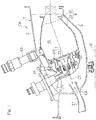
- Fig. 1 illustrates a combustor CB for a gas turbine engine equipped with a fuel injection device 1 designed in accordance with an embodiment of the present invention.
- the combustor CB is operable to mix fuel with a compressed air CA, fed from a compressor (not shown) of the gas turbine engine, and burn the resultant air-fuel mixture to produce high temperature and high pressure combustion gases, which are in turn fed to a turbine to drive this turbine.
- the combustor CB is of an annular configuration and includes an annular outer casing 3 and an inner casing 5 located radially inner side of the outer casing 3, which casings 3 and 4 are positioned in a coaxial relation with an engine rotary longitudinal axis C so as to form a combustor housing 7 having an annular inner space defined therein.
- the annular inner space of the combustor housing 7 accommodates therein an annular combustion liner 9 in a coaxial relation with the combustor housing 7.
- the combustion liner 9 is made up of an annular outer liner 11 and an annular inner liner 13 coaxially located inwardly of the annular outer liner 11 and has an annular combustion chamber 15 defined therein.
- the combustion liner 9 has a top wall provided with a plurality of fuel injection devices 1 for injecting fuel into the combustion chamber 15, which devices 1 are arranged coaxially with the engine rotary longitudinal axis C and spaced equidistantly from each other in a direction circumferentially of the combustion liner 9.
- Each of the fuel injection devices 1 includes a pilot fuel injector 21 and a main fuel injector 23.
- the main fuel injector 23 is so positioned in a round row as to surround an outer periphery of the pilot fuel injector 21 in a coaxial relation with a longitudinal axis C1 of the pilot fuel injector 21 and generate a premixed air-fuel mixture.
- Each of the fuel injection devices 1 is supported by the combustor housing 7 by means of a stem portion 26 secured to the combustor housing 7.
- An ignition plug IG for ignition extends through the outer casing 3 and the outer liner 11 and is located so as to face in a direction radially of the combustion liner 9 with its igniting end positioned in the vicinity of the fuel injection device 1.
- the compressed air CA fed from the compressor, is introduced into the annular inner space of the combustor housing 7 through a plurality of air intake tubes 27 that are positioned spaced equidistantly in a circumferential direction thereof about the engine rotary longitudinal axis C.
- the compressed air CA so introduced into the annular inner space is supplied to the fuel injection devices 1 and also into the annular combustion chamber 15 through a plurality of air intake ports each defined in the outer and inner liners 11 and 13 of the combustion liner 9.
- the stem portion 26 referred to previously forms a fuel piping unit U.
- This fuel piping unit U includes a first fuel supply system F1 for supplying fuel to the pilot fuel injector 21 for the diffusive combustion and a second fuel supply system F2 for supplying fuel to the main fuel injector 23 for the combustion of a lean premixed air-fuel mixture.
- the detailed structure of the fuel injection devices 1 is shown in Fig. 2 .
- the fuel injection device 1 includes, as hereinabove described, the pilot fuel injector 21 positioned at a radially center position, and the main fuel injector 23 located radially outwardly of the fuel injection device 1, that is, on an outer periphery side of the pilot fuel injector 21 and also includes an air injection unit 25 provided at a location intermediate between an outlet end of the pilot fuel injector 21 and the main fuel injector 23.
- the pilot fuel injector 21 includes a pilot fuel injection block 31 coupled with the stem portion 26 to inject the fuel, an air supply unit 33 provided radially outwardly of the pilot fuel injection block 31 for supplying the compressed air CA, and a tapered pilot nozzle 37 that defines a pilot flow path 35 for premixing fuel fed from the pilot fuel injection block 31, with the compressed air CA fed from the air supply unit 33, and then injecting the resultant premix into the combustion chamber 15.
- a fuel supply passage 39 that defines a flow path of the fuel is formed at a radially center location within the pilot fuel injection block 31.
- the fuel supply passage 38 of the pilot fuel injection block 31 referred to above is communicated with a first fuel introducing passage 41 forming a flow path of the fuel.
- an inner tubular body 43 is located radially outwardly of the pilot fuel injection block 31
- an outer tubular body 45 is located radially outwardly of the inner tubular body 43
- a cylindrical pilot shroud 47 having a downstream end portion formed as the pilot nozzle 37 referred to previously is located radially outwardly of the outer tubular body 45.
- the pilot fuel injector 21 and the air injection unit 25 on an outer side are defined separately from each other.
- Each of the inner tubular body 43 and the end portion (downstream end portion) of the outer tubular body 45 is tapered in a downward direction so as to have a corresponding reduced diameter.
- the pilot fuel injection block 31 includes a plurality of radially extending fuel injection ports 49. Also, an inner pilot air passage 53 is formed between the inner tubular body 43 and the outer tubular body 45 and an outer pilot air passage 55 is formed between the outer tubular body 45 and the pilot shroud 47. Those air passages 53 and 55 cooperate with each other to define the air supply unit 33 referred to previously and have respective upstream portions provided with an inner pilot swirler S1 and an outer pilot swirler S2 both operable to swirl the compressed air CA about a longitudinal axis. Accordingly, the fuel injected from the fuel injection port 49 is supplied towards the downstream side together with the compressed air CA supplied from the air passages 53 and 55.
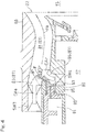
- the air injection unit 25 referred to above is formed between the pilot shroud 47 and an inner main shroud 61 located radially outwardly of the pilot shroud 47 so as to define an inner peripheral wall of the main fuel injector 23.
- the pilot shroud 47 of the pilot fuel injector 21 and the inner main shroud 61 of the main fuel injector 23 are connected together by an annular partition wall 63.
- the partition wall 63 is formed integrally with the inner main shroud 61 and is located at an axial position in the vicinity of an outlet end portion 37a of the pilot nozzle 37 of the pilot shroud 47.
- This partition wall 63 has a plurality of introduction ports 65, each in the form of an axially extending throughhole, which are distributed at respective circumferential locations.
- the inner main shroud 61 forming a part of the air injection unit 25, has a downstream end portion so shaped as to have a diameter increasing towards the downstream side.
- This downstream end portion of the inner main shroud 61 is provided with an annular partition wall plate 71 inclined radially inwardly in an upstream direction.
- the combustion chamber 15 and the air injection unit 25 are separated from each other by the partition wall plate 71.
- This partition wall plate 71 has an inner diameter side end portion having a flame stabilization plate 73 fitted thereto.
- This flame stabilization plate 73 is made up of an axially extending tubular peripheral wall portion 73a and an inclined portion 73b extending from a downstream end of the peripheral wall portion 73a towards the downstream side so as to have an increased diameter.
- the inclined portion 73b of the flame stabilization plate 73 is inclined radially outwardly and downstream with respect to the axis.
- the peripheral wall portion 73a of the flame stabilization plate 73 is secured to the inner diameter side end portion of the partition wall plate 71. Also, as best shown in Fig.
- the inclined portion 73b of the flame stabilization plate 73 extends at such an angle of inclination as to extend substantially parallel to the partition wall plate 71, and is spaced a distance from the partition wall plate 71 with a gap defined between the inclined portion 73b and the partition wall plate 71.
- the inclined portion 73b of the flame stabilization plate 73 while the gap is defined between the inclined portion 73b and the partition wall plate 71 as described above, covers the downstream side of the inner diameter side end portion of the partition wall plate 71.
- a radially extending annular gap is defined between the flame stabilization plate 73 and the downstream end portion of the pilot nozzle 37, and this annular gap defines an inner diameter side air injection opening 75, which is a first opening open towards the downstream side. Also, a portion of the partition wall plate 71, which is covered by the flame stabilization plate 73, is formed with an outer diameter side air injection opening 77, which is a second opening that extends axially.
- a portion of the compressed air CA discharged into the reservoir space 69 is injected axially from the inner diameter side air injection opening 75 into the combustion chamber 15 and the remaining portion of such compressed air CA is, after having passed through the outer diameter side air injection opening 77 into a inflow space 79, which is a gap defined between the partition wall plate 71 and the flame stabilization plate 73, injected radially outwardly from an injection port 79a, which is a downstream end of the inflow space 79, into the combustion chamber 15.
- the main fuel injector 23 has an annular premixed air-fuel mixture passage 81 for discharging and injecting the premixed air-fuel mixture towards the combustion chamber 15, an outer main air passage 83 for supplying a compressed air CAa from an axially upstream side into the premixed air-fuel mixture passage 81, and an inner main air passage 85 for supplying a compressed air CAr into the premixed air-fuel mixture passage 81 from an radially inner side towards a radially outer side.
- a cylindrical outer main shroud 86 forming a main nozzle is located coaxially on an outer side of the inner main shroud 61, and the premixed air-fuel mixture passage 81 is formed between the inner main shroud 61 and the outer main shroud 86.
- the premixed air-fuel mixture passage 81, the outer main air passage 83 and the inner main air passage 85 altogether forms a main flow passage 87 for generating a premixed air-fuel mixture in the main fuel injector 23.
- the outer main air passage 83 and the inner main air passage 85 are provided with an outer main swirler SW3 and an inner main swirler SW4, respectively, for swirling the associated compressed air CAa and CAr about corresponding longitudinal axes.
- the main fuel injector 23 is provided with a plurality of main fuel injection ports 89 for injecting fuel from an axially upstream side into the inner main air passage 85.
- the plurality of those main fuel injection ports 89 are located radially inwardly of the outer main air passage 83 and equidistantly spaced from each other in a circumferential direction about the longitudinal axis C1.
- Each of those main fuel injection ports 89 is formed as a throughhole provided at a center portion of a main fuel injection block 93 of, for example, a columnar shape so as to protrude from an annular fuel introducing chamber 91 towards an axially downstream side.
- the main fuel injection block 93 is positioned so as to confront an axially extending throughhole 97, which is defined in a flanged partition wall 95 forming a front wall (upstream side wall) of the inner main air passage 85.
- an annular gap delimited between the main fuel injection block 93 and each of the throughholes 97 in the flanged partition wall 95, both so formed as described above, is communicated with an air passage, external to the fuel injection device 1, and the compressed air passage 67 so as to define a guide air supply passage 99 for injecting the compressed air CA from the upstream side of the longitudinal axis direction into the inner main air passage 85.
- the guide air supply passage 99 is operable to inject the compressed air CAr from the upstream side of the longitudinal axis direction into the inner main air passage 85 so as to follow the fuel flow F from a main fuel injection port 89 in the main fuel injection block 93.
- a first injector unit 101 which is an upstream side structural body including the pilot injection block 31 of the pilot fuel injector 21 and the main injection block 93 of the main fuel injector 23, is supported by a combustor housing 3 by means of a stem portion 26 and a second injector unit 103, which is a downstream side structural body including the pilot nozzle 37 and the main nozzle referred to above is supported by the annular combustion liner 9 through a support flange 105 provided in an outer periphery of the downstream end portion of the outer main shroud 86.
- the first injector unit 101 and the second injector unit 103 are separately assembled and, after the assembly of each of those units 101 and 103, the first injector unit 101 is mounted on the second injector unit 103 to complete the fuel injection device 1. In this way, the first injector unit 101 is so formed as to be detachable relative to the second injector unit 103.
- the fuel injection device 1 configured as illustrated above will be described.
- the fuel F injected from the pilot fuel injector 21 and air A1 injected from the inner diameter side air injection opening 75 which is the first opening cooperatively form a pilot combustion region S in a portion within the combustion chamber 15 at the downstream side of the pilot fuel injector 21.
- the air injected from the main fuel injector 23 forms main air flow MA at the outside of the pilot combustion region S.
- the flame stabilization plate 73 includes the inclined portion 73b which is inclined radially outwardly and in a downstream direction relative to the axis, interference between the pilot combustion region S and the main air flow MA is effectively prevented, whereby flame is assuredly stabilized in the pilot combustion region S, and the combustion efficiency is improved. Therefore, it is possible to improve the combustion efficiency not only at intermediate power settings but also at low power settings.
- an air A2 supplied from the outer diameter side air injection opening 77 which is the second opening flows into the inflow space 79 defined between the flame stabilization plate 73 and the partition wall plate 71 to cool the flame stabilization plate 73.
- the flame stabilization plate 73 may be spaced apart from the partition wall plate 71 specifically by 0.7 to 2.0 mm and more specifically by about 1.0 mm.
- peripheral wall 73a which is continued to the upstream side of the inclined portion 73b, and extends in the axial direction, so as to form the outer periphery of the inner diameter side air injection opening 75 is provided in the flame stabilization plate 73, the air supplied from the outer diameter side air injection opening 77 does not flow into the inner diameter side and is assuredly discharged in the radially outward and downstream direction. Therefore, it is possible to more assuredly improve the combustion efficiency and suppress smoke.
- the pilot fuel injector 21 and the main injector 23 are connected to each other via the partition wall 63 which forms the reservoir space 69 for the compressed air CA at the downstream side of the air injection unit 25, and the introduction port 65 through which the compressed air is introduced into the reservoir space 69 is formed in the partition wall 63. Since the air flows via the reservoir space 63, the distribution of the air injected from the first opening and the second opening can be made uniform.
- the fuel injected from the pilot fuel injector 21 is assuredly diffused to the radially outer side by the pilot inner swirler SW1 and the pilot outer swirler SW2 provided in the pilot fuel injector 21.
- flame stability at the flame stabilization plate 73 is ensured, and the combustion efficiency is further assuredly improved.
Landscapes
- Engineering & Computer Science (AREA)
- Chemical & Material Sciences (AREA)
- Combustion & Propulsion (AREA)
- Mechanical Engineering (AREA)
- General Engineering & Computer Science (AREA)
- Fuel-Injection Apparatus (AREA)
- Pressure-Spray And Ultrasonic-Wave- Spray Burners (AREA)
Claims (6)
- Kraftstoffeinspritzvorrichtung (1) zum Zuführen eines Kraftstoffs zu einer Druckluft von einem Verdichter zur Verbrennung, wobei die Kraftstoffeinspritzvorrichtung Folgendes umfasst:ein Kraftstoff-Voreinspritzventil (21), das sich an einem radial mittleren Abschnitt der Kraftstoffeinspritzvorrichtung befindet und dazu konfiguriert ist, den Kraftstoff in eine Brennkammer (15) einzuspritzen;ein Kraftstoff-Haupteinspritzventil (23), das sich an einem äußeren Umfang des Kraftstoff-Voreinspritzventils befindet und dazu konfiguriert ist, ein vorgemischtes Luft-Kraftstoffgemisch aus dem Kraftstoff und Luft in die Brennkammer (15) einzuspritzen; undeine Lufteinblaseinheit (25), die sich zwischen einem Auslassendabschnitt des Kraftstoff-Voreinspritzventils und dem Kraftstoff-Haupteinspritzventil befindet und dazu konfiguriert ist, die Druckluft in die Brennkammer (15) einzublasen,dadurch gekennzeichnet, dass die Lufteinblaseinheit (25) Folgendes umfasst: eine ringförmige Trennwandplatte (71), die in einer stromaufwärtigen Richtung radial nach innen geneigt ist und an einem stromabwärtigen Endabschnitt einer inneren Haupthülle (61) vorgesehen ist, wobei der stromabwärtige Endabschnitt der inneren Haupthülle (61) derart geformt ist, dass er einen in Richtung der stromabwärtigen Seite zunehmenden Durchmesser aufweist, und einen Teil der Lufteinblaseinheit (25) bildet, wobei die Trennwandplatte (71) zum Trennen der Lufteinblaseinheit (25) von der Brennkammer (15) dient; eine Flammenstabilisierungsplatte (73), die an einem innendurchmesserseitigen Endabschnitt der Trennwandplatte (71) befestigt ist und an einer stromabwärtigen Seite der Trennwandplatte (71) vorgesehen ist; eine erste Öffnung, die zwischen der Flammenstabilisierungsplatte (73) und dem Auslassendabschnitt des Kraftstoff-Voreinspritzventils (21) vorgesehen ist und an einer stromabwärtigen Seite geöffnet ist; und eine zweite Öffnung, die in der Trennwandplatte (71) vorgesehen ist und durch die hindurch die Druckluft zu einem zwischen der Flammenstabilisierungsplatte (73) und der Trennwandplatte (71) definierten Einströmraum zugeführt wird, und
wobei die Flammenstabilisierungsplatte (73) einen geneigten Abschnitt umfasst, der in Bezug auf eine Achse (C1) in einer radial nach außen weisenden und stromabwärtigen Richtung geneigt ist. - Kraftstoffeinspritzvorrichtung (1) nach Anspruch 1, wobei die zweite Öffnung als ein Durchgangsloch vorgesehen ist, das in einem Abschnitt der Trennwandplatte (71) gebildet ist, der von der Flammenstabilisierungsplatte (73) abgedeckt ist, um sich axial zu erstrecken.
- Kraftstoffeinspritzvorrichtung (1) nach Anspruch 1 oder 2, wobei sich der geneigte Abschnitt im Wesentlichen parallel zu der Trennwandplatte (71) erstreckt.
- Kraftstoffeinspritzvorrichtung (1) nach einem der Ansprüche 1 bis 3, wobei die Flammenstabilisierungsplatte (73) einen Umfangswandabschnitt umfasst, der zu einer stromaufwärtigen Seite des geneigten Abschnitts fortgesetzt ist und sich in einer Axialrichtung erstreckt, um einen äußeren Umfang der ersten Öffnung zu bilden.
- Kraftstoffeinspritzvorrichtung (1) nach einem der Ansprüche 1 bis 4, wobei das Kraftstoff-Voreinspritzventil (21) und das Kraftstoff-Haupteinspritzventil (23) über eine Trennwand miteinander verbunden sind, die einen Speicherraum für die Druckluft auf einer stromabwärtigen Seite der Lufteinblaseinheit bildet, und die Trennwand mit einer Einbringöffnung zum Einbringen der Druckluft in den Speicherraum gebildet ist.
- Kraftstoffeinspritzvorrichtung nach einem der Ansprüche 1 bis 5, wobei das Kraftstoff-Voreinspritzventil (21) mit einem Verwirbler versehen ist, der dazu konfiguriert ist, die Druckluft um eine Achse desselben zu Verwirbeln.
Applications Claiming Priority (2)
| Application Number | Priority Date | Filing Date | Title |
|---|---|---|---|
| JP2012129681A JP5924618B2 (ja) | 2012-06-07 | 2012-06-07 | 燃料噴射装置 |
| PCT/JP2013/065432 WO2013183618A1 (ja) | 2012-06-07 | 2013-06-04 | 燃料噴射装置 |
Publications (3)
| Publication Number | Publication Date |
|---|---|
| EP2860454A1 EP2860454A1 (de) | 2015-04-15 |
| EP2860454A4 EP2860454A4 (de) | 2016-02-24 |
| EP2860454B1 true EP2860454B1 (de) | 2019-01-23 |
Family
ID=49712009
Family Applications (1)
| Application Number | Title | Priority Date | Filing Date |
|---|---|---|---|
| EP13801226.5A Active EP2860454B1 (de) | 2012-06-07 | 2013-06-04 | Kraftstoffeinspritzvorrichtung |
Country Status (5)
| Country | Link |
|---|---|
| US (1) | US10132499B2 (de) |
| EP (1) | EP2860454B1 (de) |
| JP (1) | JP5924618B2 (de) |
| CN (1) | CN104334972B (de) |
| WO (1) | WO2013183618A1 (de) |
Families Citing this family (26)
| Publication number | Priority date | Publication date | Assignee | Title |
|---|---|---|---|---|
| EP3039345B1 (de) * | 2013-08-30 | 2019-11-13 | United Technologies Corporation | Zweibrennstoffdüse mit flüssigfilmzerstäubung für einen gasturbinenmotor |
| JP6210810B2 (ja) * | 2013-09-20 | 2017-10-11 | 三菱日立パワーシステムズ株式会社 | デュアル燃料焚きガスタービン燃焼器 |
| US20150285502A1 (en) * | 2014-04-08 | 2015-10-08 | General Electric Company | Fuel nozzle shroud and method of manufacturing the shroud |
| KR101889638B1 (ko) * | 2014-05-23 | 2018-08-17 | 미츠비시 히타치 파워 시스템즈 가부시키가이샤 | 가스 터빈 연소기 및 가스 터빈 |
| JP6351071B2 (ja) * | 2014-08-18 | 2018-07-04 | 川崎重工業株式会社 | 燃料噴射装置 |
| CN104566465B (zh) * | 2014-12-31 | 2018-03-23 | 北京华清燃气轮机与煤气化联合循环工程技术有限公司 | 一种防回火型头部结构 |
| US10591164B2 (en) * | 2015-03-12 | 2020-03-17 | General Electric Company | Fuel nozzle for a gas turbine engine |
| US10859272B2 (en) * | 2016-01-15 | 2020-12-08 | Siemens Aktiengesellschaft | Combustor for a gas turbine |
| US10352570B2 (en) * | 2016-03-31 | 2019-07-16 | General Electric Company | Turbine engine fuel injection system and methods of assembling the same |
| ITUA20163988A1 (it) * | 2016-05-31 | 2017-12-01 | Nuovo Pignone Tecnologie Srl | Ugello carburante per una turbina a gas con swirler radiale e swirler assiale e turbina a gas / fuel nozzle for a gas turbine with radial swirler and axial swirler and gas turbine |
| US10502425B2 (en) * | 2016-06-03 | 2019-12-10 | General Electric Company | Contoured shroud swirling pre-mix fuel injector assembly |
| US10393382B2 (en) * | 2016-11-04 | 2019-08-27 | General Electric Company | Multi-point injection mini mixing fuel nozzle assembly |
| KR102498300B1 (ko) * | 2016-11-14 | 2023-02-09 | 한화에어로스페이스 주식회사 | 가스터빈용 연료 분사 장치 |
| JP2018146193A (ja) * | 2017-03-08 | 2018-09-20 | トヨタ自動車株式会社 | 液体燃料用バーナー |
| JP6934359B2 (ja) * | 2017-08-21 | 2021-09-15 | 三菱パワー株式会社 | 燃焼器及びその燃焼器を備えるガスタービン |
| US11408346B2 (en) | 2017-08-28 | 2022-08-09 | Kawasaki Jukogyo Kabushiki Kaisha | Fuel injector |
| CN107702147B (zh) * | 2017-09-05 | 2020-07-14 | 中国联合重型燃气轮机技术有限公司 | 燃气轮机的燃料喷嘴 |
| CN107559881B (zh) * | 2017-09-18 | 2019-09-20 | 北京航空航天大学 | 一种主燃级采用斜向喷射喷嘴的低污染燃烧室头部结构 |
| GB201803650D0 (en) * | 2018-03-07 | 2018-04-25 | Rolls Royce Plc | A lean burn fuel injector |
| US10948188B2 (en) | 2018-12-12 | 2021-03-16 | Solar Turbines Incorporated | Fuel injector with perforated plate |
| US11253823B2 (en) * | 2019-03-29 | 2022-02-22 | Delavan Inc. | Mixing nozzles |
| WO2021148896A1 (en) * | 2020-01-22 | 2021-07-29 | Turbogen Ltd. | Atomizer for gas turbine engine |
| GB202205354D0 (en) * | 2022-04-12 | 2022-05-25 | Rolls Royce Plc | Fuel delivery |
| GB202205355D0 (en) | 2022-04-12 | 2022-05-25 | Rolls Royce Plc | Gas turbine operation |
| GB202205358D0 (en) | 2022-04-12 | 2022-05-25 | Rolls Royce Plc | Loading parameters |
| CN114562592B (zh) * | 2022-04-28 | 2022-07-29 | 余姚市三力信电磁阀有限公司 | 一种超高温高压大流量快速反应电磁阀 |
Family Cites Families (70)
| Publication number | Priority date | Publication date | Assignee | Title |
|---|---|---|---|---|
| US3853273A (en) * | 1973-10-01 | 1974-12-10 | Gen Electric | Axial swirler central injection carburetor |
| JPS5077716U (de) * | 1973-11-16 | 1975-07-05 | ||
| JP2852110B2 (ja) * | 1990-08-20 | 1999-01-27 | 株式会社日立製作所 | 燃焼装置及びガスタービン装置 |
| GB9326367D0 (en) * | 1993-12-23 | 1994-02-23 | Rolls Royce Plc | Fuel injection apparatus |
| DE19508111A1 (de) * | 1995-03-08 | 1996-09-12 | Bmw Rolls Royce Gmbh | Hitzeschild-Anordnung für eine Gasturbinen-Brennkammer |
| FR2753779B1 (fr) * | 1996-09-26 | 1998-10-16 | Systeme d'injection aerodynamique d'un melange air carburant | |
| US5816049A (en) * | 1997-01-02 | 1998-10-06 | General Electric Company | Dual fuel mixer for gas turbine combustor |
| JP3709671B2 (ja) * | 1997-09-29 | 2005-10-26 | 株式会社日立製作所 | ガスタービン燃焼器 |
| US6389815B1 (en) * | 2000-09-08 | 2002-05-21 | General Electric Company | Fuel nozzle assembly for reduced exhaust emissions |
| US6381964B1 (en) * | 2000-09-29 | 2002-05-07 | General Electric Company | Multiple annular combustion chamber swirler having atomizing pilot |
| US6453660B1 (en) * | 2001-01-18 | 2002-09-24 | General Electric Company | Combustor mixer having plasma generating nozzle |
| US6546732B1 (en) * | 2001-04-27 | 2003-04-15 | General Electric Company | Methods and apparatus for cooling gas turbine engine combustors |
| US6530227B1 (en) * | 2001-04-27 | 2003-03-11 | General Electric Co. | Methods and apparatus for cooling gas turbine engine combustors |
| US6442940B1 (en) * | 2001-04-27 | 2002-09-03 | General Electric Company | Gas-turbine air-swirler attached to dome and combustor in single brazing operation |
| US20020162333A1 (en) * | 2001-05-02 | 2002-11-07 | Honeywell International, Inc., Law Dept. Ab2 | Partial premix dual circuit fuel injector |
| US6557350B2 (en) * | 2001-05-17 | 2003-05-06 | General Electric Company | Method and apparatus for cooling gas turbine engine igniter tubes |
| US6484489B1 (en) * | 2001-05-31 | 2002-11-26 | General Electric Company | Method and apparatus for mixing fuel to decrease combustor emissions |
| US6418726B1 (en) * | 2001-05-31 | 2002-07-16 | General Electric Company | Method and apparatus for controlling combustor emissions |
| US6581386B2 (en) * | 2001-09-29 | 2003-06-24 | General Electric Company | Threaded combustor baffle |
| GB0219458D0 (en) * | 2002-08-21 | 2002-09-25 | Rolls Royce Plc | Fuel injection apparatus |
| US6959535B2 (en) * | 2003-01-31 | 2005-11-01 | General Electric Company | Differential pressure induced purging fuel injectors |
| JP4065947B2 (ja) * | 2003-08-05 | 2008-03-26 | 独立行政法人 宇宙航空研究開発機構 | ガスタービン燃焼器用燃料・空気プレミキサー |
| JP2005114193A (ja) * | 2003-10-03 | 2005-04-28 | Mitsubishi Heavy Ind Ltd | ガスタービン燃焼器 |
| US7310952B2 (en) * | 2003-10-17 | 2007-12-25 | General Electric Company | Methods and apparatus for attaching swirlers to gas turbine engine combustors |
| US7340900B2 (en) * | 2004-12-15 | 2008-03-11 | General Electric Company | Method and apparatus for decreasing combustor acoustics |
| US7464553B2 (en) * | 2005-07-25 | 2008-12-16 | General Electric Company | Air-assisted fuel injector for mixer assembly of a gas turbine engine combustor |
| US7451602B2 (en) * | 2005-11-07 | 2008-11-18 | General Electric Company | Methods and apparatus for injecting fluids into turbine engines |
| JP2007162998A (ja) * | 2005-12-13 | 2007-06-28 | Kawasaki Heavy Ind Ltd | ガスタービンエンジンの燃料噴霧装置 |
| US7878000B2 (en) * | 2005-12-20 | 2011-02-01 | General Electric Company | Pilot fuel injector for mixer assembly of a high pressure gas turbine engine |
| US7596949B2 (en) * | 2006-02-23 | 2009-10-06 | General Electric Company | Method and apparatus for heat shielding gas turbine engines |
| US7762073B2 (en) * | 2006-03-01 | 2010-07-27 | General Electric Company | Pilot mixer for mixer assembly of a gas turbine engine combustor having a primary fuel injector and a plurality of secondary fuel injection ports |
| US7716931B2 (en) * | 2006-03-01 | 2010-05-18 | General Electric Company | Method and apparatus for assembling gas turbine engine |
| FR2901349B1 (fr) * | 2006-05-19 | 2008-09-05 | Snecma Sa | Chambre de combustion d'une turbomachine |
| FR2903171B1 (fr) * | 2006-06-29 | 2008-10-17 | Snecma Sa | Agencement a liaison par crabot pour chambre de combustion de turbomachine |
| US7827800B2 (en) * | 2006-10-19 | 2010-11-09 | Pratt & Whitney Canada Corp. | Combustor heat shield |
| FR2908867B1 (fr) * | 2006-11-16 | 2012-06-15 | Snecma | Dispositif d'injection d'un melange d'air et de carburant, chambre de combustion et turbomachine munies d'un tel dispositif |
| US20100251719A1 (en) * | 2006-12-29 | 2010-10-07 | Alfred Albert Mancini | Centerbody for mixer assembly of a gas turbine engine combustor |
| FR2911667B1 (fr) * | 2007-01-23 | 2009-10-02 | Snecma Sa | Systeme d'injection de carburant a double injecteur. |
| JP4421620B2 (ja) * | 2007-02-15 | 2010-02-24 | 川崎重工業株式会社 | ガスタービンエンジンの燃焼器 |
| JP4364911B2 (ja) * | 2007-02-15 | 2009-11-18 | 川崎重工業株式会社 | ガスタービンエンジンの燃焼器 |
| US8316541B2 (en) * | 2007-06-29 | 2012-11-27 | Pratt & Whitney Canada Corp. | Combustor heat shield with integrated louver and method of manufacturing the same |
| FR2918716B1 (fr) * | 2007-07-12 | 2014-02-28 | Snecma | Optimisation d'un film anti-coke dans un systeme d'injection |
| DE102007050276A1 (de) * | 2007-10-18 | 2009-04-23 | Rolls-Royce Deutschland Ltd & Co Kg | Magervormischbrenner für ein Gasturbinentriebwerk |
| US20090255120A1 (en) * | 2008-04-11 | 2009-10-15 | General Electric Company | Method of assembling a fuel nozzle |
| US8555645B2 (en) * | 2008-07-21 | 2013-10-15 | General Electric Company | Fuel nozzle centerbody and method of assembling the same |
| FR2941288B1 (fr) * | 2009-01-16 | 2011-02-18 | Snecma | Dispositif d'injection d'un melange d'air et de carburant dans une chambre de combustion de turbomachine |
| US20100263382A1 (en) * | 2009-04-16 | 2010-10-21 | Alfred Albert Mancini | Dual orifice pilot fuel injector |
| JP4733195B2 (ja) * | 2009-04-27 | 2011-07-27 | 川崎重工業株式会社 | ガスタービンエンジンの燃料噴霧装置 |
| JP4838888B2 (ja) * | 2009-05-27 | 2011-12-14 | 川崎重工業株式会社 | ガスタービン燃焼器 |
| JP2011080669A (ja) * | 2009-10-06 | 2011-04-21 | Mitsubishi Heavy Ind Ltd | 燃焼器及びガスタービン |
| FR2952166B1 (fr) * | 2009-11-05 | 2012-01-06 | Snecma | Dispositif melangeur de carburant pour chambre de combustion de turbomachine comprenant des moyens ameliores d'alimentation en air |
| JP5452206B2 (ja) | 2009-12-17 | 2014-03-26 | 株式会社平和 | 遊技機 |
| EP2530383B1 (de) * | 2010-01-28 | 2019-09-18 | Kawasaki Jukogyo Kabushiki Kaisha | Gasturbinenbrennkammer |
| FR2963061B1 (fr) * | 2010-07-26 | 2012-07-27 | Snecma | Systeme d?injection de carburant pour turbo-reacteur et procede d?assemblage d?un tel systeme d?injection |
| US8387391B2 (en) * | 2010-12-17 | 2013-03-05 | General Electric Company | Aerodynamically enhanced fuel nozzle |
| FR2971038B1 (fr) * | 2011-01-31 | 2013-02-08 | Snecma | Dispositif d'injection pour une chambre de combustion de turbomachine |
| JP5773342B2 (ja) | 2011-06-03 | 2015-09-02 | 川崎重工業株式会社 | 燃料噴射装置 |
| US9057523B2 (en) * | 2011-07-29 | 2015-06-16 | United Technologies Corporation | Microcircuit cooling for gas turbine engine combustor |
| JP5988261B2 (ja) * | 2012-06-07 | 2016-09-07 | 川崎重工業株式会社 | 燃料噴射装置 |
| US9021812B2 (en) * | 2012-07-27 | 2015-05-05 | Honeywell International Inc. | Combustor dome and heat-shield assembly |
| FR2996286B1 (fr) * | 2012-09-28 | 2014-09-12 | Snecma | Dispositif d'injection pour une chambre de combustion de turbomachine |
| US10072845B2 (en) * | 2012-11-15 | 2018-09-11 | General Electric Company | Fuel nozzle heat shield |
| US9316154B2 (en) * | 2013-03-07 | 2016-04-19 | Solar Turbines Incorporated | Gas turbine fuel injector with metering cavity |
| EP3039345B1 (de) * | 2013-08-30 | 2019-11-13 | United Technologies Corporation | Zweibrennstoffdüse mit flüssigfilmzerstäubung für einen gasturbinenmotor |
| FR3011317B1 (fr) * | 2013-10-01 | 2018-02-23 | Safran Aircraft Engines | Chambre de combustion pour turbomachine a admission d'air homogene au travers de systemes d'injection |
| CA2933536C (en) * | 2013-12-23 | 2018-06-26 | General Electric Company | Fuel nozzle structure for air-assisted fuel injection |
| US20150316266A1 (en) * | 2014-04-30 | 2015-11-05 | Siemens Aktiengesellschaft | Burner with adjustable radial fuel profile |
| US9939157B2 (en) * | 2015-03-10 | 2018-04-10 | General Electric Company | Hybrid air blast fuel nozzle |
| US10591164B2 (en) * | 2015-03-12 | 2020-03-17 | General Electric Company | Fuel nozzle for a gas turbine engine |
| GB201511841D0 (en) * | 2015-07-07 | 2015-08-19 | Rolls Royce Plc | Fuel spray nozel for a gas turbine engine |
-
2012
- 2012-06-07 JP JP2012129681A patent/JP5924618B2/ja active Active
-
2013
- 2013-06-04 WO PCT/JP2013/065432 patent/WO2013183618A1/ja unknown
- 2013-06-04 CN CN201380027505.0A patent/CN104334972B/zh active Active
- 2013-06-04 EP EP13801226.5A patent/EP2860454B1/de active Active
-
2014
- 2014-12-02 US US14/557,877 patent/US10132499B2/en active Active
Non-Patent Citations (1)
| Title |
|---|
| None * |
Also Published As
| Publication number | Publication date |
|---|---|
| CN104334972B (zh) | 2016-03-02 |
| US20150082797A1 (en) | 2015-03-26 |
| CN104334972A (zh) | 2015-02-04 |
| JP5924618B2 (ja) | 2016-05-25 |
| US10132499B2 (en) | 2018-11-20 |
| EP2860454A1 (de) | 2015-04-15 |
| WO2013183618A1 (ja) | 2013-12-12 |
| JP2013253737A (ja) | 2013-12-19 |
| EP2860454A4 (de) | 2016-02-24 |
Similar Documents
| Publication | Publication Date | Title |
|---|---|---|
| EP2860454B1 (de) | Kraftstoffeinspritzvorrichtung | |
| US9109553B2 (en) | Fuel injector | |
| US9664391B2 (en) | Gas turbine combustor | |
| EP2530382B1 (de) | Brennstoffeinspritzdüse | |
| EP2530384B1 (de) | Brennstoffeinspritzdüse | |
| EP1959196B1 (de) | Brennkammer für eine Gasturbine | |
| US20140182294A1 (en) | Gas turbine combustor | |
| CN100554785C (zh) | 用于对燃气轮机中的空气和气体进行混合的燃烧管及方法 | |
| JP4421620B2 (ja) | ガスタービンエンジンの燃焼器 | |
| CN108019775B (zh) | 具有混合套筒的小型混合燃料喷嘴组件 | |
| EP2481982B2 (de) | Mischeranordnung für einen Gasturbinenmotor | |
| AU2015268509A1 (en) | Combustion device for gas turbine engine | |
| JP2012229697A (ja) | ガスタービンエンジン内で燃料を燃焼させるための方法及び装置 | |
| JP2015114098A (ja) | 予混合パイロットノズルを備える燃料噴射器 | |
| JP2012154618A (ja) | ガスタービンエンジンのミキサーアッセンブリ | |
| US10648671B2 (en) | Fuel injection device | |
| JP2017227430A (ja) | 予混合パイロットノズルおよび燃料ノズルアセンブリ | |
| JP3990678B2 (ja) | ガスタービン燃焼器 | |
| US11060730B2 (en) | Fuel injecting device | |
| US20220275941A1 (en) | Combustion chamber comprising secondary injection systems, and fuel supply method | |
| US10697638B2 (en) | Fuel injection device | |
| WO2023140180A1 (ja) | 燃焼器及びガスタービン |
Legal Events
| Date | Code | Title | Description |
|---|---|---|---|
| PUAI | Public reference made under article 153(3) epc to a published international application that has entered the european phase |
Free format text: ORIGINAL CODE: 0009012 |
|
| 17P | Request for examination filed |
Effective date: 20150105 |
|
| AK | Designated contracting states |
Kind code of ref document: A1 Designated state(s): AL AT BE BG CH CY CZ DE DK EE ES FI FR GB GR HR HU IE IS IT LI LT LU LV MC MK MT NL NO PL PT RO RS SE SI SK SM TR |
|
| AX | Request for extension of the european patent |
Extension state: BA ME |
|
| DAX | Request for extension of the european patent (deleted) | ||
| RA4 | Supplementary search report drawn up and despatched (corrected) |
Effective date: 20160125 |
|
| RIC1 | Information provided on ipc code assigned before grant |
Ipc: F23R 3/34 20060101ALI20160119BHEP Ipc: F23R 3/18 20060101AFI20160119BHEP Ipc: F23R 3/28 20060101ALI20160119BHEP Ipc: F23R 3/14 20060101ALI20160119BHEP Ipc: F02C 7/22 20060101ALI20160119BHEP |
|
| STAA | Information on the status of an ep patent application or granted ep patent |
Free format text: STATUS: EXAMINATION IS IN PROGRESS |
|
| 17Q | First examination report despatched |
Effective date: 20180213 |
|
| GRAP | Despatch of communication of intention to grant a patent |
Free format text: ORIGINAL CODE: EPIDOSNIGR1 |
|
| STAA | Information on the status of an ep patent application or granted ep patent |
Free format text: STATUS: GRANT OF PATENT IS INTENDED |
|
| INTG | Intention to grant announced |
Effective date: 20180807 |
|
| GRAS | Grant fee paid |
Free format text: ORIGINAL CODE: EPIDOSNIGR3 |
|
| GRAA | (expected) grant |
Free format text: ORIGINAL CODE: 0009210 |
|
| STAA | Information on the status of an ep patent application or granted ep patent |
Free format text: STATUS: THE PATENT HAS BEEN GRANTED |
|
| RAP1 | Party data changed (applicant data changed or rights of an application transferred) |
Owner name: KAWASAKI JUKOGYO KABUSHIKI KAISHA Owner name: JAPAN AEROSPACE EXPLORATION AGENCY |
|
| RIN1 | Information on inventor provided before grant (corrected) |
Inventor name: FUJIWARA, HITOSHI Inventor name: HORIKAWA, ATSUSHI Inventor name: KOBAYASHI, MASAYOSHI Inventor name: MATSUYAMA, RYUSUKE |
|
| AK | Designated contracting states |
Kind code of ref document: B1 Designated state(s): AL AT BE BG CH CY CZ DE DK EE ES FI FR GB GR HR HU IE IS IT LI LT LU LV MC MK MT NL NO PL PT RO RS SE SI SK SM TR |
|
| REG | Reference to a national code |
Ref country code: GB Ref legal event code: FG4D |
|
| REG | Reference to a national code |
Ref country code: CH Ref legal event code: EP |
|
| REG | Reference to a national code |
Ref country code: AT Ref legal event code: REF Ref document number: 1091743 Country of ref document: AT Kind code of ref document: T Effective date: 20190215 |
|
| REG | Reference to a national code |
Ref country code: IE Ref legal event code: FG4D |
|
| REG | Reference to a national code |
Ref country code: DE Ref legal event code: R096 Ref document number: 602013050275 Country of ref document: DE |
|
| REG | Reference to a national code |
Ref country code: NL Ref legal event code: MP Effective date: 20190123 |
|
| PG25 | Lapsed in a contracting state [announced via postgrant information from national office to epo] |
Ref country code: NL Free format text: LAPSE BECAUSE OF FAILURE TO SUBMIT A TRANSLATION OF THE DESCRIPTION OR TO PAY THE FEE WITHIN THE PRESCRIBED TIME-LIMIT Effective date: 20190123 |
|
| PG25 | Lapsed in a contracting state [announced via postgrant information from national office to epo] |
Ref country code: ES Free format text: LAPSE BECAUSE OF FAILURE TO SUBMIT A TRANSLATION OF THE DESCRIPTION OR TO PAY THE FEE WITHIN THE PRESCRIBED TIME-LIMIT Effective date: 20190123 Ref country code: PL Free format text: LAPSE BECAUSE OF FAILURE TO SUBMIT A TRANSLATION OF THE DESCRIPTION OR TO PAY THE FEE WITHIN THE PRESCRIBED TIME-LIMIT Effective date: 20190123 Ref country code: NO Free format text: LAPSE BECAUSE OF FAILURE TO SUBMIT A TRANSLATION OF THE DESCRIPTION OR TO PAY THE FEE WITHIN THE PRESCRIBED TIME-LIMIT Effective date: 20190423 Ref country code: SE Free format text: LAPSE BECAUSE OF FAILURE TO SUBMIT A TRANSLATION OF THE DESCRIPTION OR TO PAY THE FEE WITHIN THE PRESCRIBED TIME-LIMIT Effective date: 20190123 Ref country code: PT Free format text: LAPSE BECAUSE OF FAILURE TO SUBMIT A TRANSLATION OF THE DESCRIPTION OR TO PAY THE FEE WITHIN THE PRESCRIBED TIME-LIMIT Effective date: 20190523 Ref country code: FI Free format text: LAPSE BECAUSE OF FAILURE TO SUBMIT A TRANSLATION OF THE DESCRIPTION OR TO PAY THE FEE WITHIN THE PRESCRIBED TIME-LIMIT Effective date: 20190123 Ref country code: LT Free format text: LAPSE BECAUSE OF FAILURE TO SUBMIT A TRANSLATION OF THE DESCRIPTION OR TO PAY THE FEE WITHIN THE PRESCRIBED TIME-LIMIT Effective date: 20190123 |
|
| REG | Reference to a national code |
Ref country code: AT Ref legal event code: MK05 Ref document number: 1091743 Country of ref document: AT Kind code of ref document: T Effective date: 20190123 |
|
| PG25 | Lapsed in a contracting state [announced via postgrant information from national office to epo] |
Ref country code: IS Free format text: LAPSE BECAUSE OF FAILURE TO SUBMIT A TRANSLATION OF THE DESCRIPTION OR TO PAY THE FEE WITHIN THE PRESCRIBED TIME-LIMIT Effective date: 20190523 Ref country code: BG Free format text: LAPSE BECAUSE OF FAILURE TO SUBMIT A TRANSLATION OF THE DESCRIPTION OR TO PAY THE FEE WITHIN THE PRESCRIBED TIME-LIMIT Effective date: 20190423 Ref country code: RS Free format text: LAPSE BECAUSE OF FAILURE TO SUBMIT A TRANSLATION OF THE DESCRIPTION OR TO PAY THE FEE WITHIN THE PRESCRIBED TIME-LIMIT Effective date: 20190123 Ref country code: HR Free format text: LAPSE BECAUSE OF FAILURE TO SUBMIT A TRANSLATION OF THE DESCRIPTION OR TO PAY THE FEE WITHIN THE PRESCRIBED TIME-LIMIT Effective date: 20190123 Ref country code: GR Free format text: LAPSE BECAUSE OF FAILURE TO SUBMIT A TRANSLATION OF THE DESCRIPTION OR TO PAY THE FEE WITHIN THE PRESCRIBED TIME-LIMIT Effective date: 20190424 Ref country code: LV Free format text: LAPSE BECAUSE OF FAILURE TO SUBMIT A TRANSLATION OF THE DESCRIPTION OR TO PAY THE FEE WITHIN THE PRESCRIBED TIME-LIMIT Effective date: 20190123 |
|
| REG | Reference to a national code |
Ref country code: DE Ref legal event code: R097 Ref document number: 602013050275 Country of ref document: DE |
|
| PG25 | Lapsed in a contracting state [announced via postgrant information from national office to epo] |
Ref country code: AL Free format text: LAPSE BECAUSE OF FAILURE TO SUBMIT A TRANSLATION OF THE DESCRIPTION OR TO PAY THE FEE WITHIN THE PRESCRIBED TIME-LIMIT Effective date: 20190123 Ref country code: CZ Free format text: LAPSE BECAUSE OF FAILURE TO SUBMIT A TRANSLATION OF THE DESCRIPTION OR TO PAY THE FEE WITHIN THE PRESCRIBED TIME-LIMIT Effective date: 20190123 Ref country code: SK Free format text: LAPSE BECAUSE OF FAILURE TO SUBMIT A TRANSLATION OF THE DESCRIPTION OR TO PAY THE FEE WITHIN THE PRESCRIBED TIME-LIMIT Effective date: 20190123 Ref country code: RO Free format text: LAPSE BECAUSE OF FAILURE TO SUBMIT A TRANSLATION OF THE DESCRIPTION OR TO PAY THE FEE WITHIN THE PRESCRIBED TIME-LIMIT Effective date: 20190123 Ref country code: IT Free format text: LAPSE BECAUSE OF FAILURE TO SUBMIT A TRANSLATION OF THE DESCRIPTION OR TO PAY THE FEE WITHIN THE PRESCRIBED TIME-LIMIT Effective date: 20190123 Ref country code: DK Free format text: LAPSE BECAUSE OF FAILURE TO SUBMIT A TRANSLATION OF THE DESCRIPTION OR TO PAY THE FEE WITHIN THE PRESCRIBED TIME-LIMIT Effective date: 20190123 Ref country code: EE Free format text: LAPSE BECAUSE OF FAILURE TO SUBMIT A TRANSLATION OF THE DESCRIPTION OR TO PAY THE FEE WITHIN THE PRESCRIBED TIME-LIMIT Effective date: 20190123 |
|
| PG25 | Lapsed in a contracting state [announced via postgrant information from national office to epo] |
Ref country code: SM Free format text: LAPSE BECAUSE OF FAILURE TO SUBMIT A TRANSLATION OF THE DESCRIPTION OR TO PAY THE FEE WITHIN THE PRESCRIBED TIME-LIMIT Effective date: 20190123 |
|
| PLBE | No opposition filed within time limit |
Free format text: ORIGINAL CODE: 0009261 |
|
| STAA | Information on the status of an ep patent application or granted ep patent |
Free format text: STATUS: NO OPPOSITION FILED WITHIN TIME LIMIT |
|
| PG25 | Lapsed in a contracting state [announced via postgrant information from national office to epo] |
Ref country code: AT Free format text: LAPSE BECAUSE OF FAILURE TO SUBMIT A TRANSLATION OF THE DESCRIPTION OR TO PAY THE FEE WITHIN THE PRESCRIBED TIME-LIMIT Effective date: 20190123 |
|
| 26N | No opposition filed |
Effective date: 20191024 |
|
| PG25 | Lapsed in a contracting state [announced via postgrant information from national office to epo] |
Ref country code: MC Free format text: LAPSE BECAUSE OF FAILURE TO SUBMIT A TRANSLATION OF THE DESCRIPTION OR TO PAY THE FEE WITHIN THE PRESCRIBED TIME-LIMIT Effective date: 20190123 |
|
| REG | Reference to a national code |
Ref country code: CH Ref legal event code: PL |
|
| PG25 | Lapsed in a contracting state [announced via postgrant information from national office to epo] |
Ref country code: SI Free format text: LAPSE BECAUSE OF FAILURE TO SUBMIT A TRANSLATION OF THE DESCRIPTION OR TO PAY THE FEE WITHIN THE PRESCRIBED TIME-LIMIT Effective date: 20190123 |
|
| REG | Reference to a national code |
Ref country code: BE Ref legal event code: MM Effective date: 20190630 |
|
| PG25 | Lapsed in a contracting state [announced via postgrant information from national office to epo] |
Ref country code: TR Free format text: LAPSE BECAUSE OF FAILURE TO SUBMIT A TRANSLATION OF THE DESCRIPTION OR TO PAY THE FEE WITHIN THE PRESCRIBED TIME-LIMIT Effective date: 20190123 |
|
| PG25 | Lapsed in a contracting state [announced via postgrant information from national office to epo] |
Ref country code: IE Free format text: LAPSE BECAUSE OF NON-PAYMENT OF DUE FEES Effective date: 20190604 |
|
| PG25 | Lapsed in a contracting state [announced via postgrant information from national office to epo] |
Ref country code: LU Free format text: LAPSE BECAUSE OF NON-PAYMENT OF DUE FEES Effective date: 20190604 Ref country code: BE Free format text: LAPSE BECAUSE OF NON-PAYMENT OF DUE FEES Effective date: 20190630 Ref country code: CH Free format text: LAPSE BECAUSE OF NON-PAYMENT OF DUE FEES Effective date: 20190630 Ref country code: LI Free format text: LAPSE BECAUSE OF NON-PAYMENT OF DUE FEES Effective date: 20190630 |
|
| PG25 | Lapsed in a contracting state [announced via postgrant information from national office to epo] |
Ref country code: CY Free format text: LAPSE BECAUSE OF FAILURE TO SUBMIT A TRANSLATION OF THE DESCRIPTION OR TO PAY THE FEE WITHIN THE PRESCRIBED TIME-LIMIT Effective date: 20190123 |
|
| PG25 | Lapsed in a contracting state [announced via postgrant information from national office to epo] |
Ref country code: HU Free format text: LAPSE BECAUSE OF FAILURE TO SUBMIT A TRANSLATION OF THE DESCRIPTION OR TO PAY THE FEE WITHIN THE PRESCRIBED TIME-LIMIT; INVALID AB INITIO Effective date: 20130604 Ref country code: MT Free format text: LAPSE BECAUSE OF FAILURE TO SUBMIT A TRANSLATION OF THE DESCRIPTION OR TO PAY THE FEE WITHIN THE PRESCRIBED TIME-LIMIT Effective date: 20190123 |
|
| PG25 | Lapsed in a contracting state [announced via postgrant information from national office to epo] |
Ref country code: MK Free format text: LAPSE BECAUSE OF FAILURE TO SUBMIT A TRANSLATION OF THE DESCRIPTION OR TO PAY THE FEE WITHIN THE PRESCRIBED TIME-LIMIT Effective date: 20190123 |
|
| PGFP | Annual fee paid to national office [announced via postgrant information from national office to epo] |
Ref country code: FR Payment date: 20230523 Year of fee payment: 11 Ref country code: DE Payment date: 20230516 Year of fee payment: 11 |
|
| PGFP | Annual fee paid to national office [announced via postgrant information from national office to epo] |
Ref country code: GB Payment date: 20230518 Year of fee payment: 11 |