EP2481982B2 - Mischeranordnung für einen Gasturbinenmotor - Google Patents
Mischeranordnung für einen Gasturbinenmotor Download PDFInfo
- Publication number
- EP2481982B2 EP2481982B2 EP12151964.9A EP12151964A EP2481982B2 EP 2481982 B2 EP2481982 B2 EP 2481982B2 EP 12151964 A EP12151964 A EP 12151964A EP 2481982 B2 EP2481982 B2 EP 2481982B2
- Authority
- EP
- European Patent Office
- Prior art keywords
- swirler
- outer radial
- mixer
- radial wall
- vanes
- Prior art date
- Legal status (The legal status is an assumption and is not a legal conclusion. Google has not performed a legal analysis and makes no representation as to the accuracy of the status listed.)
- Active
Links
Images


Classifications
-
- F—MECHANICAL ENGINEERING; LIGHTING; HEATING; WEAPONS; BLASTING
- F23—COMBUSTION APPARATUS; COMBUSTION PROCESSES
- F23C—METHODS OR APPARATUS FOR COMBUSTION USING FLUID FUEL OR SOLID FUEL SUSPENDED IN A CARRIER GAS OR AIR
- F23C7/00—Combustion apparatus characterised by arrangements for air supply
- F23C7/002—Combustion apparatus characterised by arrangements for air supply the air being submitted to a rotary or spinning motion
- F23C7/004—Combustion apparatus characterised by arrangements for air supply the air being submitted to a rotary or spinning motion using vanes
-
- F—MECHANICAL ENGINEERING; LIGHTING; HEATING; WEAPONS; BLASTING
- F23—COMBUSTION APPARATUS; COMBUSTION PROCESSES
- F23R—GENERATING COMBUSTION PRODUCTS OF HIGH PRESSURE OR HIGH VELOCITY, e.g. GAS-TURBINE COMBUSTION CHAMBERS
- F23R3/00—Continuous combustion chambers using liquid or gaseous fuel
- F23R3/02—Continuous combustion chambers using liquid or gaseous fuel characterised by the air-flow or gas-flow configuration
- F23R3/04—Air inlet arrangements
- F23R3/10—Air inlet arrangements for primary air
- F23R3/12—Air inlet arrangements for primary air inducing a vortex
- F23R3/14—Air inlet arrangements for primary air inducing a vortex by using swirl vanes
-
- F—MECHANICAL ENGINEERING; LIGHTING; HEATING; WEAPONS; BLASTING
- F23—COMBUSTION APPARATUS; COMBUSTION PROCESSES
- F23R—GENERATING COMBUSTION PRODUCTS OF HIGH PRESSURE OR HIGH VELOCITY, e.g. GAS-TURBINE COMBUSTION CHAMBERS
- F23R3/00—Continuous combustion chambers using liquid or gaseous fuel
- F23R3/28—Continuous combustion chambers using liquid or gaseous fuel characterised by the fuel supply
- F23R3/286—Continuous combustion chambers using liquid or gaseous fuel characterised by the fuel supply having fuel-air premixing devices
Definitions
- the subject matter disclosed herein relates generally to combustors for gas turbine engines and more particularly to mixer assemblies for gas turbine engines.
- Gas turbine engines such as those used to power modem aircraft, to power sea vessels, to generate electrical power, and in industrial applications, include a compressor for pressurizing a supply of air, a combustor for burning a hydrocarbon fuel in the presence of the pressurized air, and a turbine for extracting energy from the resultant combustion gases.
- the compressor, combustor, and turbine are disposed about a central engine axis with the compressor disposed axially upstream or forward of the combustor and the turbine disposed axially downstream of the combustor.
- fuel is injected into and combusted in the combustor with compressed air from the compressor thereby generating high-temperature combustion exhaust gases, which pass through the turbine and produce rotational shaft power.
- the shaft power is used to drive a compressor to provide air to the combustion process to generate the high energy gases. Additionally, the shaft power is used to, for example, drive a generator for producing electricity, or drive a fan to produce high momentum gases for producing thrust.
- An exemplary combustor features an annular combustion chamber defined between a radially inboard liner and a radially outboard liner extending aft from a forward bulkhead wall.
- the radially outboard liner extends circumferentially about and is radially spaced from the inboard liner, with the combustion chamber extending fore to aft between the liners.
- a plurality of circumferentially distributed fuel injectors are mounted in the forward bulkhead wall and project into the forward end of the annular combustion chamber to supply the fuel to be combusted.
- Air swirlers proximate to the fuel injectors impart a swirl to inlet air entering the forward end of the combustion chamber at the bulkhead wall to provide rapid mixing of the fuel and inlet air.
- Such a combustor is known, for example, from US 6 161 387 A .
- PLPP piloted lean premixed/partially premixed pre-vaporized combustor
- Mixer assemblies for existing PLPP combustors typically include a pilot mixer surrounded by a main mixer with a fuel manifold provided between the two mixers to inject fuel radially into the cavity of the main mixer through fuel injection holes.
- the main mixer typically employs air swirlers proximate and upstream of the fuel injection holes to impart a swirl to the air entering the main mixer and to provide rapid mixing of the air and the fuel, which is injected perpendicularly into the cross flow of the air atomizing the fuel for mixing with the air.
- the level of atomization and mixing in this main mixer configuration is largely dependent upon the penetration of the fuel into the air, which in turn is dependent upon the ratio of the momentum of the fuel to the momentum of the air.
- the degree of atomization and mixing may vary greatly for different gas turbine engine operating conditions (e.g., low power conditions where there is poor atomization and mixing may result in higher emissions than high power conditions where there is better atomization and mixing).
- the fuel injection holes are typically located downstream of the point where the air swirlers produce the maximum turbulence, the degree of atomization and mixing is not maximized, increasing the amount of emissions.
- the risk of flashback, flame holding and autoignition greatly increases due to the low velocity regions associated with fuel jets and walls.
- a highly possible source for flashback, flame holding and autoignition in the typical main mixer is caused by a wake region that can form downstream of the fuel injection holes where injected fuel that has not sufficiently penetrated into the cross flow of the air (e.g., when air is flowing at low velocity) will gather and potentially ignite.
- Another possible source is related to boundary layers along the wall, which is thickened by fuel jets due to reduced velocity.
- EP 2093489 A2 discloses a radially outward air blast fuel injector having an outer air circuit with an outer radial air swirler and an outlet, and an inner air circuit with an inner axial air swirler and an outlet configured to direct air towards the exit portion of the outer air circuit.
- the injector further comprises a fuel circuit radially outboard of the inner air circuit and having an exit communicating with the outer air circuit upstream of the exit portion of the outer circuit.
- a mixer assembly comprising a swirler housing having a first axial swirler in a forward wall of the housing and a second radial swirler located within a radially outer wall of the swirler housing. Fuel injection ports are provided in a radially inner wall of the swirler housing.
- US 5816049 discloses a dual fuel mixer for a gas turbine engine combustor. It comprises a holder which connects a radial, outer swirler and an axial inner swirler.
- the holder has, in section an airfoil shape.
- Fuel injection openings are provided in a radially outwardly pointing surface of the holder, generally parallel to the axis of the radial outer swirler.
- the openings are constructed with bleed passages or atomisers. Such constructions are complicated.
- a mixer assembly for a gas turbine engine including a main mixer with fuel injection holes located between at least one radial swirler and at least one axial swirler, wherein the fuel injected into the main mixer is atomized and dispersed by the air flowing through the radial swirler and the axial swirler.
- This configuration reduces the dependence upon the ratio of the momentum of the fuel to the momentum of the air, increases the degree of atomization and mixing by injecting the fuel at a point of high turbulence, and reduces the potential for flame holding by reducing the potential for forming a wake region and lengthening the potential mixing distance.
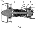
- FIG. 1 is a schematic diagram of an exemplary embodiment of a gas turbine engine 10.
- the gas turbine engine 10 is depicted as a turbofan that incorporates a fan section 20, a compressor section 30, a combustion section 40, and a turbine section 50.
- the combustion section 40 incorporates a combustor 100 that includes a plurality of fuel injectors 150 that are positioned annularly about a centerline 2 of the engine 10 upstream of the turbines 52, 54.
- the terms “forward” or “upstream” are used to refer to directions and positions located axially closer toward a fuel/air intake side of a combustion system than directions and positions referenced as “aft” or “downstream.”
- the fuel injectors 150 are inserted into and provide fuel to one or more combustion chambers for mixing and/or ignition. It is to be understood that the combustor 100 and fuel injector 150 as disclosed herein are not limited in application to the depicted embodiment of a gas turbine engine 10, but are applicable to other types of gas turbine engines, such as those used to power modem aircraft, to power sea vessels, to generate electrical power, and in industrial applications.
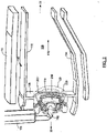
- FIG. 2 is a partial perspective view of an exemplary embodiment of a combustor 100 of a gas turbine engine 10.
- the combustor 100 is positioned between the compressor section 30 and the turbine section 50 of a gas turbine engine 10.
- the exemplary combustor 100 includes an annular combustion chamber 130 bounded by an inner (inboard) wall 132 and an outer (outboard) wall 134 and a forward bulkhead wall 136 spanning between the walls 132, 134 at the forward end of the combustor 100.
- the bulkhead wall 136 of the combustor 100 carries a plurality of mixer assemblies 200, including the fuel nozzle 152 of a fuel injector 150, a main mixer 220, and a pilot mixer 210.
- the combustor 100 may include a plurality of mixer assemblies 200 circumferentially distributed and mounted at the forward end of the combustor 100.
- a number of sparkplugs (not shown) are positioned with their working ends along a forward portion of the combustion chamber 130 to initiate combustion of the fuel and air mixture.
- the combusting mixture is driven downstream within the combustor 100 along a principal flowpath 170 toward the turbine section 50 of the engine 10.
- the fuel and air provided to the pilot mixer 210 produce a primary combustion zone 110 within a central portion of the combustion chamber 130.
- the fuel and air provided to the main mixer 220 produce a secondary combustion zone 120 in the combustion chamber 130 that is radially outwardly spaced from and concentrically surrounds the primary combustion zone 110.
- FIG. 3 is an enlarged partial perspective view of an exemplary embodiment of the mixer assembly 200 for the exemplary combustor 100 of FIG. 2 .
- the exemplary mixer assembly 200 includes a main mixer 220 and a pilot mixer 210.
- the pilot mixer 210 and the main mixer 220 are concentrically arranged with the pilot mixer 210 located in the center of the main mixer 220, which surrounds a portion of the pilot mixer 210.
- the mixer assembly 200 has a centerline axis 218.
- the pilot mixer 210 includes an annular pilot mixer housing 212 separating and sheltering the pilot mixer 210 from the main mixer 220.
- the main mixer 220 further includes an annular main mixer outer radial wall 222 radially surrounding a portion of the annular pilot mixer housing 212, the outer surface of which forms an annular main mixer inner radial wall 219, and a main mixer forward wall 224 substantially perpendicular to and connecting the annular main mixer outer radial wall 222 and the annular main mixer inner radial wall 219, forming a main mixer annular cavity 228.
- the annular main mixer outer radial wall 222 further incorporates a first outer radial wall swirler 240, while the main mixer forward wall 224 further incorporates a first forward wall swirler 230 and a plurality of fuel injection holes 226 circumferentially distributed between the first outer radial wall swirler 240 and the first forward wall swirler 230 around the main mixer forward wall 224.
- the fuel injection holes 226 can be located proximate the first forward wall swirler 230 in the main mixer forward wall 224 as well.
- the fuel injection holes 226 are in flow communication with a fuel manifold (not shown), which in turn is in flow communication with a fuel supply.
- the exemplary embodiments of mixer assemblies 200 can also be used with gaseous fuel or partially vaporized fuel.
- the first outer radial wall swirler 240 is positioned on a first side of the fuel injection holes 226, while the first forward wall swirler 230 is positioned on a second side of the fuel injection holes 226.
- the first side is substantially opposite of the second side.
- the first outer radial wall swirler 240 is incorporated into the annular main mixer outer radial wall 222 and has an axis 248 oriented substantially radially to the centerline axis 218 of the mixer assembly 200.
- the first forward wall swirler 230 is incorporated into the main mixer forward wall 224 and is oriented substantially parallel or axially to the centerline axis 218 of the mixer assembly 200.
- the swirlers 230, 240 each have a plurality of vanes for swirling air traveling through the swirlers to mix the air and the fuel dispensed by the fuel injection holes 226.
- the first outer radial wall swirler 240 includes a first plurality of vanes 242 forming a first plurality of air passages 244 between the vanes 242.
- the vanes 242 are oriented at an angle with respect to axis 248 to cause the air to rotate in the main mixer annular cavity 228 in a first direction (e.g., clockwise).
- the first forward wall swirler 230 includes a second plurality of vanes 232 forming a second plurality of air passages 234 between the vanes 232.
- the vanes 232 are oriented at an angle with respect to the centerline axis 218 to cause the air to rotate in the main mixer annular cavity 228 in a second direction (e.g., counterclockwise).
- the air flowing through the first outer radial wall swirler 240 will be swirled in a first direction and the air flowing through the first forward wall swirler 230 will be swirled in a direction substantially opposite of the first direction.
- the air flowing through the first outer radial wall swirler 240 has an axis 248 oriented substantially radially to the centerline axis 218 of the mixer assembly 200, while the air flowing through the first forward wall swirler 230 has an axis oriented substantially axially to the centerline axis 218 of the mixer assembly 200.
- the fuel is injected through the fuel injection holes 226 between the radial first outer radial wall swirler 240 and the axial first forward wall swirler 230.
- the fuel is injected through the fuel injection holes 226 that are oriented substantially perpendicularly to axis 248 and the flow of air from the radial first outer radial wall swirler 240, which atomizes and disperses the fuel.
- the fuel then is atomized and dispersed again by the flow of air from the axial first forward wall swirler 230, thus atomizing the fuel by airflow from two sides.
- An intense mixing region 229 of fuel and air is created within annular main mixer cavity 228 axially adjacent to the fuel injection holes 226, allowing the majority of fuel and air to be mixed before entering the downstream end of the annular main mixer cavity 228.
- This configuration reduces the dependence upon the ratio of the momentum of the fuel to the momentum of the air, increases the degree of atomization and mixing by injecting the fuel at a point of high turbulence, and reduces the potential for flame holding by reducing the potential for forming a wake region and lengthening the potential mixing distance.
- the configuration of the vanes in the swirlers may be altered to vary the swirl direction of air flowing and are not limited to the exemplary swirl directions indicated.
- the number of radial and axial swirlers can be modified (e.g., the first outer radial wall swirler 240 can be replaced by a plurality of radial swirlers and the first forward wall swirler 230 can be replaced by a plurality of axial swirlers).
- FIG. 4 is an enlarged partial perspective view of another exemplary embodiment of the mixer assembly 200 for the exemplary combustor 100 of FIG. 2 .
- the exemplary mixer assembly 200 includes a main mixer 220 and a pilot mixer 210.
- the pilot mixer 210 includes an annular pilot mixer housing 212 separating and sheltering the pilot mixer 210 from the main mixer 220.
- the main mixer 220 further includes an annular main mixer outer radial wall 222 radially surrounding a portion of the annular pilot mixer housing 212, the outer surface of which forms an annular main mixer inner radial wall 219, and a main mixer forward wall 224 substantially perpendicular to and connecting the annular main mixer outer radial wall 222 and the annular main mixer inner radial wall 219, forming a main mixer annular cavity 228.
- the annular main mixer outer radial wall 222 further incorporates a plurality of outer radial wall swirlers, including a first outer radial wall swirler 270, a second outer radial wall swirler 280, and a third outer radial wall swirler 290, while the main mixer forward wall 224 further incorporates a plurality of forward wall swirlers, including a first forward wall swirler 250, a second forward wall swirler 260, and a plurality of fuel injection holes 226 circumferentially distributed between the second forward wall swirler 260 and the first outer radial wall swirler 270 around the main mixer forward wall 224.
- the fuel injection holes 226 can be located proximate the second forward wall swirler 260 in the main mixer forward wall 224 as well.
- the fuel injection holes 226 are in flow communication with a fuel manifold (not shown), which in turn is in flow communication with a fuel supply.
- a fuel manifold not shown
- the exemplary embodiments of mixer assemblies 200 can also be used with gaseous fuel or partially vaporized fuel. As can be seen in FIG.
- the first, second, and third outer radial wall swirlers 270, 280, 290 are positioned on a first side of the fuel injection holes 226, while the first and second forward wall swirlers 250, 260 are positioned on the second side of the fuel injection holes 226.
- the first side is substantially opposite of the second side.
- the first, second, and third outer radial wall swirlers 270, 280, 290 are incorporated into the annular main mixer outer radial wall 222 and each have an axis 248 oriented substantially radially to the centerline axis 218 of the mixer assembly 200.
- the first and second forward wall swirlers 250, 260 are incorporated into the main mixer forward wall 224 and are oriented substantially parallel or axially to the centerline axis 218 of the mixer assembly 200.
- Swirlers 250, 260, 270, 280, 290 each have a plurality of vanes for swirling air traveling through the swirlers to mix the air and the fuel dispensed by the fuel injection holes 226.
- the first outer radial wall swirler 270 includes a first plurality of vanes 272 forming a first plurality of air passages 274 between the vanes 272.
- the vanes 272 are oriented at an angle with respect to axis 248 to cause the air to rotate in the main mixer annular cavity 228 in a first direction (e.g., clockwise).
- the second outer radial wall swirler 280 includes a second plurality of vanes 282 forming a second plurality of air passages 284 between the vanes 282.
- the vanes 282 are oriented at an angle with respect to axis 248 to cause the air to rotate in the main mixer annular cavity 228 in a second direction (e.g., counterclockwise).
- the third outer radial wall swirler 290 includes a third plurality of vanes 292 forming a third plurality of air passages 294 between the vanes 292.
- the vanes 292 are oriented at an angle with respect to axis 248 to cause the air to rotate in the main mixer annular cavity 228 in a third direction.
- the third direction can be substantially the same as the first direction which is substantially opposite of the second direction.
- the first forward wall swirler 250 includes a fourth plurality of vanes 252 forming a fourth plurality of air passages 254 between the vanes 252.
- the vanes 252 are oriented at an angle with respect to the centerline axis 218 to cause the air to rotate in the main mixer annular cavity 228 in a fourth direction (e.g., counterclockwise).
- the second forward wall swirler 260 includes a fifth plurality of vanes 262 forming a fifth plurality of air passages 264 between the vanes 262.
- the vanes 262 are oriented at an angle with respect to the centerline axis 218 to cause the air to rotate in the main mixer annular cavity 228 in a fifth direction (e.g., clockwise).
- the fourth direction is substantially opposite of the fifth direction.
- the clockwise air passing through the first outer radial wall swirler 270 and the third outer radial wall swirler 290 counter-rotates against the counterclockwise air passing through the second outer radial wall swirler 280, increasing the turbulence, which improves mixing.
- the counterclockwise air passing through the first forward wall swirler 250 counter-rotates against the clockwise air passing through the second forward wall swirler 260, increasing the turbulence, which improves mixing.
- the air flowing through the first, second, and third outer radial wall swirlers 270, 280, 290 has an axis 248 oriented substantially radially to the centerline axis 218 of the mixer assembly 200, while the air flowing through the first and second forward wall swirlers 250, 260 has an axis oriented substantially axially to the centerline axis 218 of the mixer assembly 200.
- the fuel is injected through the fuel injection holes 226 between the radial first, second, and third outer radial wall swirlers 270, 280, 290 and the axial first and second forward wall swirlers 250, 260.
- the fuel is injected through the fuel injection holes 226 that are oriented substantially perpendicularly to axis 248 and the flow of air from the plurality of outer radial wall swirlers (first, second, and third outer radial wall swirlers 270, 280, 290), which atomizes and disperses the fuel.
- the fuel then is atomized and dispersed again by the flow of air from the plurality of forward wall swirlers (first and second forward wall swirlers 240, 250), thus atomizing the fuel by airflow from two sides.
- An intense mixing region 229 of fuel and air is created within annular main mixer cavity 228 axially adjacent to the fuel injection holes 226, allowing the majority of fuel and air to be mixed before entering the downstream end of the annular main mixer cavity 228.
- the number of axial swirlers, the number of radial swirlers, and the configuration of the vanes in the swirlers may be altered to vary the swirl direction of air flowing and are not limited to the exemplary swirl directions indicated.
Landscapes
- Engineering & Computer Science (AREA)
- Chemical & Material Sciences (AREA)
- Combustion & Propulsion (AREA)
- Mechanical Engineering (AREA)
- General Engineering & Computer Science (AREA)
- Nozzles For Spraying Of Liquid Fuel (AREA)
Claims (13)
- Mischeranordnung (200) für ein Gasturbinentriebwerk, umfassend:
einen Hauptmischer (220), umfassend:eine ringförmige innere radiale Wand (219);eine ringförmige äußere radiale Wand (222), die wenigstens einen Abschnitt der ringförmigen inneren radialen Wand (219) umgibt, wobei die ringförmige äußere radiale Wand (222) einen ersten äußeren radialen Wandverwirbler (240) mit einer ersten Achse (248) aufweist, die im Wesentlichen radial zu einer Mittelachse (218) der Mischeranordnung (200) orientiert ist;eine vordere Wand (224), die im Wesentlichen senkrecht zu der ringförmigen inneren radialen Wand (219) und der ringförmigen äußeren radialen Wand (222) ist und diese verbindet und einen ringförmigen Hohlraum (228) bildet, dadurch gekennzeichnet, dass die vordere Wand (224) einen ersten vorderen Wandverwirbler (230) mit einer zweiten Achse aufweist, die im Wesentlichen axial zur Mittelachse (218) der Mischeranordnung (200) orientiert ist; unddass die Mischeranordnung Folgendes umfassteine Vielzahl von Treibstoffeinspritzöffnungen (226) in der vorderen Wand (224) zwischen dem ersten äußeren radialen Wandverwirbler (240) und dem ersten vorderen Wandverwirbler (230), wobei der erste äußere radiale Wandverwirbler (240) auf einer ersten Seite der Vielzahl von Treibstoffeinspritzöffnungen (226) ist und der erste vordere Wandverwirbler (230) auf einer zweiten Seite der Vielzahl von Treibstoffeinspritzöffnungen (226) ist;wobei
die Vielzahl von Treibstoffeinspritzöffnungen (226) im Wesentlichen senkrecht zu der ersten Achse (248) orientiert ist. - Mischeranordnung nach Anspruch 1, wobeider erste äußere radiale Wandverwirbler (240) ferner eine erste Vielzahl von Schaufeln (242) umfasst, die eine erste Vielzahl von Luftdurchlässen (244) bildet, wobei die erste Vielzahl von Schaufeln (242) in einem Winkel in Bezug auf die erste Achse (248) orientiert ist, um die Luft, die durch den ersten äußeren radialen Wandverwirbler (240) tritt, in einer ersten Richtung rotieren zu lassen; undder erste vordere Wandverwirbler (230) ferner eine zweite Vielzahl von Schaufeln (232) umfasst, die eine zweite Vielzahl von Luftdurchlässen (234) bildet, wobei die zweite Vielzahl von Schaufeln (232) in einem Winkel in Bezug auf die zweite Achse orientiert ist, um die Luft, die durch den ersten vorderen Wandverwirbler (230) tritt, in einer zweiten Richtung rotieren zu lassen.
- Mischeranordnung nach Anspruch 2, wobei die erste Richtung im Wesentlichen zur zweiten Richtung entgegengesetzt ist.
- Mischeranordnung nach einem der vorangehenden Ansprüche, ferner umfassend einen Vormischer (210), von dem wenigstens ein Abschnitt von dem Hauptmischer (220) umgeben ist, wobei der Vormischer (210) ein ringförmiges Gehäuse (212) mit einer Außenfläche umfasst, die die ringförmige innere Wand (219) des Hauptmischers (220) bildet.
- Mischeranordnung nach einem der vorangehenden Ansprüche, ferner umfassend einen Treibstoffverteiler in Fließverbindung mit der Vielzahl von Treibstoffeinspritzöffnungen (226).
- Mischeranordnung nach einem vorangehenden Anspruch, wobei die erste Seite im Wesentlichen zur zweiten Seite entgegengesetzt ist.
- Mischeranordnung nach einem vorangehenden Anspruch, wobei die ringförmige äußere radiale Wand (222) eine Vielzahl von äußeren radialen Wandverwirblern (270, 280, 290) mit einer ersten Achse aufweist, die im Wesentlichen radial zur Mittelachse (218) der Mischeranordnung (200) orientiert ist;
wobei die Vielzahl von Treibstoffeinspritzöffnungen (226) in der vorderen Wand (224) zwischen der Vielzahl von äußeren radialen Wandverwirblern (270, 280, 290) und dem ersten vorderen Wandverwirbler ist, wobei die Vielzahl von äußeren radialen Wandverwirblern (270, 280, 290) auf der ersten Seite der Vielzahl von Treibstoffeinspritzöffnungen (226) ist und der erste vordere Wandverwirbler (230) auf der zweiten Seite der Vielzahl von Treibstoffeinspritzöffnungen (226) ist. - Mischeranordnung nach Anspruch 7, wobei die Vielzahl von äußeren radialen Wandverwirblern (270, 280, 290) Folgendes umfasst:einen ersten äußeren radialen Wandverwirbler (270), der eine erste Vielzahl von Schaufeln (272) umfasst, die eine erste Vielzahl von Luftdurchlässen (274) bildet, wobei die erste Vielzahl von Schaufeln (272) in einem Winkel in Bezug auf die erste Achse (248) orientiert ist, um die Luft, die durch den ersten äußeren radialen Wandverwirbler (270) tritt, in einer ersten Richtung rotieren zu lassen; undeinen zweiten äußeren radialen Wandverwirbler (280), der eine zweite Vielzahl von Schaufeln (282) umfasst, die eine zweite Vielzahl von Luftdurchlässen (284) bildet, wobei die zweite Vielzahl von Schaufeln (282) in einem Winkel in Bezug auf die erste Achse (248) orientiert ist, um die Luft, die durch den zweiten äußeren radialen Wandverwirbler (280) tritt, in einer zweiten Richtung rotieren zu lassen.
- Mischeranordnung nach Anspruch 7 oder 8, wobei die erste Richtung im Wesentlichen zur zweiten Richtung entgegengesetzt ist.
- Mischeranordnung nach Anspruch 7, 8 oder 9, wobei die Vielzahl äußerer radialer Wandverwirbler ferner einen dritten äußeren radialen Wandverwirbler (290) umfasst, der eine dritte Vielzahl von Schaufeln (292) umfasst, die eine dritte Vielzahl von Luftdurchlässen (294) bildet, wobei die dritte Vielzahl von Schaufeln (292) in einem Winkel in Bezug auf die erste Achse (248) orientiert ist, um die Luft, die durch den dritten äußeren radialen Wandverwirbler (290) tritt, in einer dritten Richtung rotieren zu lassen, wobei die erste Richtung wahlweise im Wesentlichen die gleiche wie die dritte Richtung ist.
- Mischeranordnung nach einem der Ansprüche 7 bis 10, wobei der erste vordere Wandverwirbler (250) eine erste Vielzahl von Schaufeln (252) umfasst, die eine erste Vielzahl von Luftdurchlässen (254) bildet, wobei die erste Vielzahl von Schaufeln (252) in einem Winkel in Bezug auf die zweite Achse orientiert ist, um Luft, die durch den ersten vorderen Wandverwirbler (252) tritt, in einer vierten Richtung rotieren zu lassen.
- Mischeranordnung nach einem der Ansprüche 7 bis 11, ferner umfassend einen zweiten vorderen Wandverwirbler (260) in der Nähe des ersten vorderen Wandverwirblers (250).
- Mischeranordnung nach Anspruch 12, wobei der zweite vordere Wandverwirbler (260) ferner eine zweite Vielzahl von Schaufeln (262) umfasst, die eine zweite Vielzahl von Luftdurchlässen (264) bildet, wobei die zweite Vielzahl von Schaufeln (262) in einem Winkel in Bezug auf die zweite Achse orientiert ist, um Luft, die durch den zweiten vorderen Wandverwirbler tritt, in einer fünften Richtung rotieren zu lassen, wobei die vierte Richtung wahlweise im Wesentlichen zur fünften Richtung entgegengesetzt ist.
Applications Claiming Priority (1)
| Application Number | Priority Date | Filing Date | Title |
|---|---|---|---|
| US13/014,388 US8973368B2 (en) | 2011-01-26 | 2011-01-26 | Mixer assembly for a gas turbine engine |
Publications (3)
| Publication Number | Publication Date |
|---|---|
| EP2481982A1 EP2481982A1 (de) | 2012-08-01 |
| EP2481982B1 EP2481982B1 (de) | 2015-07-08 |
| EP2481982B2 true EP2481982B2 (de) | 2022-04-13 |
Family
ID=45509309
Family Applications (1)
| Application Number | Title | Priority Date | Filing Date |
|---|---|---|---|
| EP12151964.9A Active EP2481982B2 (de) | 2011-01-26 | 2012-01-20 | Mischeranordnung für einen Gasturbinenmotor |
Country Status (2)
| Country | Link |
|---|---|
| US (1) | US8973368B2 (de) |
| EP (1) | EP2481982B2 (de) |
Families Citing this family (32)
| Publication number | Priority date | Publication date | Assignee | Title |
|---|---|---|---|---|
| US9920932B2 (en) * | 2011-01-26 | 2018-03-20 | United Technologies Corporation | Mixer assembly for a gas turbine engine |
| JP5772245B2 (ja) * | 2011-06-03 | 2015-09-02 | 川崎重工業株式会社 | 燃料噴射装置 |
| US20130232978A1 (en) * | 2012-03-12 | 2013-09-12 | Zhongtao Dai | Fuel air premixer for gas turbine engine |
| US9347669B2 (en) * | 2012-10-01 | 2016-05-24 | Alstom Technology Ltd. | Variable length combustor dome extension for improved operability |
| US10378456B2 (en) | 2012-10-01 | 2019-08-13 | Ansaldo Energia Switzerland AG | Method of operating a multi-stage flamesheet combustor |
| US10060630B2 (en) | 2012-10-01 | 2018-08-28 | Ansaldo Energia Ip Uk Limited | Flamesheet combustor contoured liner |
| US9897317B2 (en) | 2012-10-01 | 2018-02-20 | Ansaldo Energia Ip Uk Limited | Thermally free liner retention mechanism |
| EP3008391B1 (de) | 2013-06-11 | 2020-05-06 | United Technologies Corporation | Brennkammer mit axialer stufung für einen gasturbinenmotor |
| KR102129052B1 (ko) * | 2013-11-12 | 2020-07-02 | 한화에어로스페이스 주식회사 | 스월러 어셈블리 |
| US9534788B2 (en) | 2014-04-03 | 2017-01-03 | General Electric Company | Air fuel premixer for low emissions gas turbine combustor |
| US9976743B2 (en) | 2014-07-03 | 2018-05-22 | United Technologies Corporation | Dilution hole assembly |
| US9759356B2 (en) | 2014-07-03 | 2017-09-12 | United Technologies Corporation | Insulated flowpath assembly |
| US10208673B2 (en) | 2014-07-03 | 2019-02-19 | United Technologies Corporation | Fuel dispensing apparatus and method of operation |
| US9915480B2 (en) | 2014-07-03 | 2018-03-13 | United Technologies Corporation | Tube assembly |
| EP3043116A1 (de) * | 2015-01-09 | 2016-07-13 | United Technologies Corporation | Mischeranordnung für einen gasturbinenmotor |
| US10047959B2 (en) * | 2015-12-29 | 2018-08-14 | Pratt & Whitney Canada Corp. | Fuel injector for fuel spray nozzle |
| US10337738B2 (en) | 2016-06-22 | 2019-07-02 | General Electric Company | Combustor assembly for a turbine engine |
| US11022313B2 (en) * | 2016-06-22 | 2021-06-01 | General Electric Company | Combustor assembly for a turbine engine |
| US10393382B2 (en) * | 2016-11-04 | 2019-08-27 | General Electric Company | Multi-point injection mini mixing fuel nozzle assembly |
| US11149952B2 (en) * | 2016-12-07 | 2021-10-19 | Raytheon Technologies Corporation | Main mixer in an axial staged combustor for a gas turbine engine |
| US10527286B2 (en) * | 2016-12-16 | 2020-01-07 | Delavan, Inc | Staged radial air swirler with radial liquid fuel distributor |
| GB201802251D0 (en) | 2018-02-12 | 2018-03-28 | Rolls Royce Plc | An air swirler arrangement for a fuel injector of a combustion chamber |
| GB201803650D0 (en) * | 2018-03-07 | 2018-04-25 | Rolls Royce Plc | A lean burn fuel injector |
| US11181269B2 (en) | 2018-11-15 | 2021-11-23 | General Electric Company | Involute trapped vortex combustor assembly |
| GB202019219D0 (en) | 2020-12-07 | 2021-01-20 | Rolls Royce Plc | Lean burn combustor |
| GB202019222D0 (en) * | 2020-12-07 | 2021-01-20 | Rolls Royce Plc | Lean burn combustor |
| GB2601563B (en) * | 2020-12-07 | 2024-11-06 | Rolls Royce Plc | Lean burn combustor |
| US12454909B2 (en) | 2021-12-03 | 2025-10-28 | General Electric Company | Combustor size rating for a gas turbine engine using hydrogen fuel |
| US12331932B2 (en) | 2022-01-31 | 2025-06-17 | General Electric Company | Turbine engine fuel mixer |
| US12215866B2 (en) | 2022-02-18 | 2025-02-04 | General Electric Company | Combustor for a turbine engine having a fuel-air mixer including a set of mixing passages |
| US20240255147A1 (en) * | 2023-01-31 | 2024-08-01 | Rtx Corporation | Air purge for gas turbine engine fuel injector assembly |
| US20240263792A1 (en) * | 2023-02-07 | 2024-08-08 | Pratt & Whitney Canada Corp. | Perforated plate fuel distributor with simiplified swirler |
Citations (14)
| Publication number | Priority date | Publication date | Assignee | Title |
|---|---|---|---|---|
| US3703259A (en) † | 1971-05-03 | 1972-11-21 | Gen Electric | Air blast fuel atomizer |
| US3946552A (en) † | 1973-09-10 | 1976-03-30 | General Electric Company | Fuel injection apparatus |
| US5165241A (en) † | 1991-02-22 | 1992-11-24 | General Electric Company | Air fuel mixer for gas turbine combustor |
| US5515680A (en) † | 1993-03-18 | 1996-05-14 | Hitachi, Ltd. | Apparatus and method for mixing gaseous fuel and air for combustion including injection at a reverse flow bend |
| US5540056A (en) † | 1994-01-12 | 1996-07-30 | General Electric Company | Cyclonic prechamber with a centerbody for a gas turbine engine combustor |
| US5816049A (en) † | 1997-01-02 | 1998-10-06 | General Electric Company | Dual fuel mixer for gas turbine combustor |
| US6161387A (en) † | 1998-10-30 | 2000-12-19 | United Technologies Corporation | Multishear fuel injector |
| EP1193450A1 (de) † | 2000-09-29 | 2002-04-03 | General Electric Company | Mischvorrichtung mit mehreren Verwirbelungsvorrichtungen |
| US6381964B1 (en) † | 2000-09-29 | 2002-05-07 | General Electric Company | Multiple annular combustion chamber swirler having atomizing pilot |
| US6609377B2 (en) † | 2000-09-29 | 2003-08-26 | General Electric Company | Multiple injector combustor |
| US6799427B2 (en) † | 2002-03-07 | 2004-10-05 | Snecma Moteurs | Multimode system for injecting an air/fuel mixture into a combustion chamber |
| US20070028624A1 (en) † | 2005-07-25 | 2007-02-08 | General Electric Company | Mixer assembly for combustor of a gas turbine engine having a plurality of counter-rotating swirlers |
| GB2456753A (en) † | 2006-12-29 | 2009-07-29 | Gen Electric | Centerbody for mixer assembly of a gas turbine engine combustor |
| EP2093490A1 (de) † | 2008-02-21 | 2009-08-26 | Electrolux Home Products Corporation N.V. | Backofen mit Abgasreinigungsanordnung |
Family Cites Families (38)
| Publication number | Priority date | Publication date | Assignee | Title |
|---|---|---|---|---|
| FR2484020A1 (fr) * | 1980-06-06 | 1981-12-11 | Snecma | Ensemble d'injection de carburant pour chambre de turboreacteur |
| US6560967B1 (en) | 1998-05-29 | 2003-05-13 | Jeffrey Mark Cohen | Method and apparatus for use with a gas fueled combustor |
| US6082111A (en) | 1998-06-11 | 2000-07-04 | Siemens Westinghouse Power Corporation | Annular premix section for dry low-NOx combustors |
| US6354072B1 (en) | 1999-12-10 | 2002-03-12 | General Electric Company | Methods and apparatus for decreasing combustor emissions |
| US6272840B1 (en) | 2000-01-13 | 2001-08-14 | Cfd Research Corporation | Piloted airblast lean direct fuel injector |
| JP4058749B2 (ja) | 2000-02-16 | 2008-03-12 | 株式会社デンソー | 電磁駆動装置およびそれを用いた電磁弁 |
| US6389815B1 (en) | 2000-09-08 | 2002-05-21 | General Electric Company | Fuel nozzle assembly for reduced exhaust emissions |
| US6367262B1 (en) | 2000-09-29 | 2002-04-09 | General Electric Company | Multiple annular swirler |
| US6418726B1 (en) | 2001-05-31 | 2002-07-16 | General Electric Company | Method and apparatus for controlling combustor emissions |
| US6484489B1 (en) | 2001-05-31 | 2002-11-26 | General Electric Company | Method and apparatus for mixing fuel to decrease combustor emissions |
| US6865889B2 (en) | 2002-02-01 | 2005-03-15 | General Electric Company | Method and apparatus to decrease combustor emissions |
| EP1499800B1 (de) | 2002-04-26 | 2011-06-29 | Rolls-Royce Corporation | Kraftstoffvormischmodul für turbomotorbrennkammer |
| US6871501B2 (en) * | 2002-12-03 | 2005-03-29 | General Electric Company | Method and apparatus to decrease gas turbine engine combustor emissions |
| DE10326720A1 (de) | 2003-06-06 | 2004-12-23 | Rolls-Royce Deutschland Ltd & Co Kg | Brenner für eine Gasturbinenbrennkammer |
| JP4065947B2 (ja) * | 2003-08-05 | 2008-03-26 | 独立行政法人 宇宙航空研究開発機構 | ガスタービン燃焼器用燃料・空気プレミキサー |
| US7013635B2 (en) | 2003-12-30 | 2006-03-21 | United Technologies Corporation | Augmentor with axially displaced vane system |
| US7546740B2 (en) | 2004-05-11 | 2009-06-16 | United Technologies Corporation | Nozzle |
| US7065972B2 (en) * | 2004-05-21 | 2006-06-27 | Honeywell International, Inc. | Fuel-air mixing apparatus for reducing gas turbine combustor exhaust emissions |
| US7059135B2 (en) * | 2004-08-30 | 2006-06-13 | General Electric Company | Method to decrease combustor emissions |
| JP2006300448A (ja) | 2005-04-22 | 2006-11-02 | Mitsubishi Heavy Ind Ltd | ガスタービンの燃焼器 |
| US7779636B2 (en) | 2005-05-04 | 2010-08-24 | Delavan Inc | Lean direct injection atomizer for gas turbine engines |
| US20070028618A1 (en) | 2005-07-25 | 2007-02-08 | General Electric Company | Mixer assembly for combustor of a gas turbine engine having a main mixer with improved fuel penetration |
| US7565803B2 (en) | 2005-07-25 | 2009-07-28 | General Electric Company | Swirler arrangement for mixer assembly of a gas turbine engine combustor having shaped passages |
| US7464553B2 (en) | 2005-07-25 | 2008-12-16 | General Electric Company | Air-assisted fuel injector for mixer assembly of a gas turbine engine combustor |
| US7537646B2 (en) | 2005-10-11 | 2009-05-26 | United Technologies Corporation | Fuel system and method of reducing emission |
| US7878000B2 (en) | 2005-12-20 | 2011-02-01 | General Electric Company | Pilot fuel injector for mixer assembly of a high pressure gas turbine engine |
| US7506510B2 (en) | 2006-01-17 | 2009-03-24 | Delavan Inc | System and method for cooling a staged airblast fuel injector |
| US7762073B2 (en) | 2006-03-01 | 2010-07-27 | General Electric Company | Pilot mixer for mixer assembly of a gas turbine engine combustor having a primary fuel injector and a plurality of secondary fuel injection ports |
| US7712315B2 (en) | 2006-04-20 | 2010-05-11 | United Technologies Corporation | Augmentor variable vane flame stabilization |
| US8037688B2 (en) | 2006-09-26 | 2011-10-18 | United Technologies Corporation | Method for control of thermoacoustic instabilities in a combustor |
| US7631500B2 (en) | 2006-09-29 | 2009-12-15 | General Electric Company | Methods and apparatus to facilitate decreasing combustor acoustics |
| GB0625016D0 (en) | 2006-12-15 | 2007-01-24 | Rolls Royce Plc | Fuel injector |
| GB2456147B (en) | 2008-01-03 | 2010-07-14 | Rolls Royce Plc | Fuel Injector Assembly for Gas Turbine Engines |
| US7926744B2 (en) | 2008-02-21 | 2011-04-19 | Delavan Inc | Radially outward flowing air-blast fuel injector for gas turbine engine |
| GB0820560D0 (en) | 2008-11-11 | 2008-12-17 | Rolls Royce Plc | Fuel injector |
| US8209987B2 (en) | 2008-11-26 | 2012-07-03 | United Technologies Corporation | Augmentor pilot |
| US20100263382A1 (en) | 2009-04-16 | 2010-10-21 | Alfred Albert Mancini | Dual orifice pilot fuel injector |
| JP4733195B2 (ja) | 2009-04-27 | 2011-07-27 | 川崎重工業株式会社 | ガスタービンエンジンの燃料噴霧装置 |
-
2011
- 2011-01-26 US US13/014,388 patent/US8973368B2/en active Active
-
2012
- 2012-01-20 EP EP12151964.9A patent/EP2481982B2/de active Active
Patent Citations (14)
| Publication number | Priority date | Publication date | Assignee | Title |
|---|---|---|---|---|
| US3703259A (en) † | 1971-05-03 | 1972-11-21 | Gen Electric | Air blast fuel atomizer |
| US3946552A (en) † | 1973-09-10 | 1976-03-30 | General Electric Company | Fuel injection apparatus |
| US5165241A (en) † | 1991-02-22 | 1992-11-24 | General Electric Company | Air fuel mixer for gas turbine combustor |
| US5515680A (en) † | 1993-03-18 | 1996-05-14 | Hitachi, Ltd. | Apparatus and method for mixing gaseous fuel and air for combustion including injection at a reverse flow bend |
| US5540056A (en) † | 1994-01-12 | 1996-07-30 | General Electric Company | Cyclonic prechamber with a centerbody for a gas turbine engine combustor |
| US5816049A (en) † | 1997-01-02 | 1998-10-06 | General Electric Company | Dual fuel mixer for gas turbine combustor |
| US6161387A (en) † | 1998-10-30 | 2000-12-19 | United Technologies Corporation | Multishear fuel injector |
| EP1193450A1 (de) † | 2000-09-29 | 2002-04-03 | General Electric Company | Mischvorrichtung mit mehreren Verwirbelungsvorrichtungen |
| US6381964B1 (en) † | 2000-09-29 | 2002-05-07 | General Electric Company | Multiple annular combustion chamber swirler having atomizing pilot |
| US6609377B2 (en) † | 2000-09-29 | 2003-08-26 | General Electric Company | Multiple injector combustor |
| US6799427B2 (en) † | 2002-03-07 | 2004-10-05 | Snecma Moteurs | Multimode system for injecting an air/fuel mixture into a combustion chamber |
| US20070028624A1 (en) † | 2005-07-25 | 2007-02-08 | General Electric Company | Mixer assembly for combustor of a gas turbine engine having a plurality of counter-rotating swirlers |
| GB2456753A (en) † | 2006-12-29 | 2009-07-29 | Gen Electric | Centerbody for mixer assembly of a gas turbine engine combustor |
| EP2093490A1 (de) † | 2008-02-21 | 2009-08-26 | Electrolux Home Products Corporation N.V. | Backofen mit Abgasreinigungsanordnung |
Also Published As
| Publication number | Publication date |
|---|---|
| EP2481982B1 (de) | 2015-07-08 |
| EP2481982A1 (de) | 2012-08-01 |
| US8973368B2 (en) | 2015-03-10 |
| US20120186256A1 (en) | 2012-07-26 |
Similar Documents
| Publication | Publication Date | Title |
|---|---|---|
| EP2481982B2 (de) | Mischeranordnung für einen Gasturbinenmotor | |
| US10718524B2 (en) | Mixer assembly for a gas turbine engine | |
| EP2481987B1 (de) | Mischeranordnung für einen Gasturbinenmotor | |
| US10480791B2 (en) | Fuel injector to facilitate reduced NOx emissions in a combustor system | |
| US7762073B2 (en) | Pilot mixer for mixer assembly of a gas turbine engine combustor having a primary fuel injector and a plurality of secondary fuel injection ports | |
| EP2479498B1 (de) | Gasturbinenbrennkammer und Betriebsverfahren | |
| US6968692B2 (en) | Fuel premixing module for gas turbine engine combustor | |
| EP2354663B1 (de) | Gasturbinenbrennkammer mit gestufter Verbrennung | |
| US6381964B1 (en) | Multiple annular combustion chamber swirler having atomizing pilot | |
| JP6196868B2 (ja) | 燃料ノズルとその組立方法 | |
| EP2481985B1 (de) | Kraftstoffeinspritzanordnung | |
| CN104406197A (zh) | 一种采用径向旋流进气燃油分级方案的低排放回流燃烧室 | |
| US12228282B2 (en) | Gas turbine fuel nozzle having an inner air passage and plural outer fuel passages | |
| US11906165B2 (en) | Gas turbine nozzle having an inner air swirler passage and plural exterior fuel passages | |
| EP3425281B1 (de) | Pilotdüse mit inline-vormischung | |
| US20140144150A1 (en) | Fuel nozzle for use in a turbine engine and method of assembly | |
| GB2451517A (en) | Pilot mixer for mixer assembly of a gas turbine engine combustor having a primary fuel injector and a plurality of secondary fuel injection ports | |
| EP3043116A1 (de) | Mischeranordnung für einen gasturbinenmotor | |
| CA2596789C (en) | Pilot mixer for mixer assembly of a gas turbine engine combustor having a primary fuel injector and a plurality of secondary fuel injection ports | |
| Dai et al. | Mixer Assembly for a Gas Turbine Engine |
Legal Events
| Date | Code | Title | Description |
|---|---|---|---|
| PUAI | Public reference made under article 153(3) epc to a published international application that has entered the european phase |
Free format text: ORIGINAL CODE: 0009012 |
|
| AK | Designated contracting states |
Kind code of ref document: A1 Designated state(s): AL AT BE BG CH CY CZ DE DK EE ES FI FR GB GR HR HU IE IS IT LI LT LU LV MC MK MT NL NO PL PT RO RS SE SI SK SM TR |
|
| AX | Request for extension of the european patent |
Extension state: BA ME |
|
| 17P | Request for examination filed |
Effective date: 20130122 |
|
| GRAP | Despatch of communication of intention to grant a patent |
Free format text: ORIGINAL CODE: EPIDOSNIGR1 |
|
| INTG | Intention to grant announced |
Effective date: 20150210 |
|
| GRAS | Grant fee paid |
Free format text: ORIGINAL CODE: EPIDOSNIGR3 |
|
| GRAA | (expected) grant |
Free format text: ORIGINAL CODE: 0009210 |
|
| AK | Designated contracting states |
Kind code of ref document: B1 Designated state(s): AL AT BE BG CH CY CZ DE DK EE ES FI FR GB GR HR HU IE IS IT LI LT LU LV MC MK MT NL NO PL PT RO RS SE SI SK SM TR |
|
| REG | Reference to a national code |
Ref country code: GB Ref legal event code: FG4D |
|
| REG | Reference to a national code |
Ref country code: AT Ref legal event code: REF Ref document number: 735705 Country of ref document: AT Kind code of ref document: T Effective date: 20150715 Ref country code: CH Ref legal event code: EP |
|
| REG | Reference to a national code |
Ref country code: IE Ref legal event code: FG4D |
|
| REG | Reference to a national code |
Ref country code: DE Ref legal event code: R096 Ref document number: 602012008493 Country of ref document: DE |
|
| REG | Reference to a national code |
Ref country code: AT Ref legal event code: MK05 Ref document number: 735705 Country of ref document: AT Kind code of ref document: T Effective date: 20150708 |
|
| REG | Reference to a national code |
Ref country code: NL Ref legal event code: MP Effective date: 20150708 |
|
| REG | Reference to a national code |
Ref country code: FR Ref legal event code: PLFP Year of fee payment: 5 |
|
| REG | Reference to a national code |
Ref country code: LT Ref legal event code: MG4D |
|
| PG25 | Lapsed in a contracting state [announced via postgrant information from national office to epo] |
Ref country code: FI Free format text: LAPSE BECAUSE OF FAILURE TO SUBMIT A TRANSLATION OF THE DESCRIPTION OR TO PAY THE FEE WITHIN THE PRESCRIBED TIME-LIMIT Effective date: 20150708 Ref country code: NO Free format text: LAPSE BECAUSE OF FAILURE TO SUBMIT A TRANSLATION OF THE DESCRIPTION OR TO PAY THE FEE WITHIN THE PRESCRIBED TIME-LIMIT Effective date: 20151008 Ref country code: LV Free format text: LAPSE BECAUSE OF FAILURE TO SUBMIT A TRANSLATION OF THE DESCRIPTION OR TO PAY THE FEE WITHIN THE PRESCRIBED TIME-LIMIT Effective date: 20150708 Ref country code: GR Free format text: LAPSE BECAUSE OF FAILURE TO SUBMIT A TRANSLATION OF THE DESCRIPTION OR TO PAY THE FEE WITHIN THE PRESCRIBED TIME-LIMIT Effective date: 20151009 Ref country code: LT Free format text: LAPSE BECAUSE OF FAILURE TO SUBMIT A TRANSLATION OF THE DESCRIPTION OR TO PAY THE FEE WITHIN THE PRESCRIBED TIME-LIMIT Effective date: 20150708 |
|
| PG25 | Lapsed in a contracting state [announced via postgrant information from national office to epo] |
Ref country code: ES Free format text: LAPSE BECAUSE OF FAILURE TO SUBMIT A TRANSLATION OF THE DESCRIPTION OR TO PAY THE FEE WITHIN THE PRESCRIBED TIME-LIMIT Effective date: 20150708 Ref country code: PL Free format text: LAPSE BECAUSE OF FAILURE TO SUBMIT A TRANSLATION OF THE DESCRIPTION OR TO PAY THE FEE WITHIN THE PRESCRIBED TIME-LIMIT Effective date: 20150708 Ref country code: PT Free format text: LAPSE BECAUSE OF FAILURE TO SUBMIT A TRANSLATION OF THE DESCRIPTION OR TO PAY THE FEE WITHIN THE PRESCRIBED TIME-LIMIT Effective date: 20151109 Ref country code: SE Free format text: LAPSE BECAUSE OF FAILURE TO SUBMIT A TRANSLATION OF THE DESCRIPTION OR TO PAY THE FEE WITHIN THE PRESCRIBED TIME-LIMIT Effective date: 20150708 Ref country code: HR Free format text: LAPSE BECAUSE OF FAILURE TO SUBMIT A TRANSLATION OF THE DESCRIPTION OR TO PAY THE FEE WITHIN THE PRESCRIBED TIME-LIMIT Effective date: 20150708 Ref country code: RS Free format text: LAPSE BECAUSE OF FAILURE TO SUBMIT A TRANSLATION OF THE DESCRIPTION OR TO PAY THE FEE WITHIN THE PRESCRIBED TIME-LIMIT Effective date: 20150708 Ref country code: IS Free format text: LAPSE BECAUSE OF FAILURE TO SUBMIT A TRANSLATION OF THE DESCRIPTION OR TO PAY THE FEE WITHIN THE PRESCRIBED TIME-LIMIT Effective date: 20151108 Ref country code: AT Free format text: LAPSE BECAUSE OF FAILURE TO SUBMIT A TRANSLATION OF THE DESCRIPTION OR TO PAY THE FEE WITHIN THE PRESCRIBED TIME-LIMIT Effective date: 20150708 |
|
| REG | Reference to a national code |
Ref country code: DE Ref legal event code: R026 Ref document number: 602012008493 Country of ref document: DE |
|
| PLBI | Opposition filed |
Free format text: ORIGINAL CODE: 0009260 |
|
| PG25 | Lapsed in a contracting state [announced via postgrant information from national office to epo] |
Ref country code: CZ Free format text: LAPSE BECAUSE OF FAILURE TO SUBMIT A TRANSLATION OF THE DESCRIPTION OR TO PAY THE FEE WITHIN THE PRESCRIBED TIME-LIMIT Effective date: 20150708 Ref country code: DK Free format text: LAPSE BECAUSE OF FAILURE TO SUBMIT A TRANSLATION OF THE DESCRIPTION OR TO PAY THE FEE WITHIN THE PRESCRIBED TIME-LIMIT Effective date: 20150708 Ref country code: EE Free format text: LAPSE BECAUSE OF FAILURE TO SUBMIT A TRANSLATION OF THE DESCRIPTION OR TO PAY THE FEE WITHIN THE PRESCRIBED TIME-LIMIT Effective date: 20150708 Ref country code: SK Free format text: LAPSE BECAUSE OF FAILURE TO SUBMIT A TRANSLATION OF THE DESCRIPTION OR TO PAY THE FEE WITHIN THE PRESCRIBED TIME-LIMIT Effective date: 20150708 Ref country code: IT Free format text: LAPSE BECAUSE OF FAILURE TO SUBMIT A TRANSLATION OF THE DESCRIPTION OR TO PAY THE FEE WITHIN THE PRESCRIBED TIME-LIMIT Effective date: 20150708 |
|
| PLAX | Notice of opposition and request to file observation + time limit sent |
Free format text: ORIGINAL CODE: EPIDOSNOBS2 |
|
| 26 | Opposition filed |
Opponent name: SNECMA Effective date: 20160405 |
|
| PG25 | Lapsed in a contracting state [announced via postgrant information from national office to epo] |
Ref country code: RO Free format text: LAPSE BECAUSE OF FAILURE TO SUBMIT A TRANSLATION OF THE DESCRIPTION OR TO PAY THE FEE WITHIN THE PRESCRIBED TIME-LIMIT Effective date: 20150708 Ref country code: BE Free format text: LAPSE BECAUSE OF NON-PAYMENT OF DUE FEES Effective date: 20160131 |
|
| PG25 | Lapsed in a contracting state [announced via postgrant information from national office to epo] |
Ref country code: LU Free format text: LAPSE BECAUSE OF FAILURE TO SUBMIT A TRANSLATION OF THE DESCRIPTION OR TO PAY THE FEE WITHIN THE PRESCRIBED TIME-LIMIT Effective date: 20160120 Ref country code: SI Free format text: LAPSE BECAUSE OF FAILURE TO SUBMIT A TRANSLATION OF THE DESCRIPTION OR TO PAY THE FEE WITHIN THE PRESCRIBED TIME-LIMIT Effective date: 20150708 |
|
| REG | Reference to a national code |
Ref country code: CH Ref legal event code: PL |
|
| PLBB | Reply of patent proprietor to notice(s) of opposition received |
Free format text: ORIGINAL CODE: EPIDOSNOBS3 |
|
| PG25 | Lapsed in a contracting state [announced via postgrant information from national office to epo] |
Ref country code: MC Free format text: LAPSE BECAUSE OF FAILURE TO SUBMIT A TRANSLATION OF THE DESCRIPTION OR TO PAY THE FEE WITHIN THE PRESCRIBED TIME-LIMIT Effective date: 20150708 |
|
| RAP2 | Party data changed (patent owner data changed or rights of a patent transferred) |
Owner name: UNITED TECHNOLOGIES CORPORATION |
|
| PG25 | Lapsed in a contracting state [announced via postgrant information from national office to epo] |
Ref country code: CH Free format text: LAPSE BECAUSE OF NON-PAYMENT OF DUE FEES Effective date: 20160131 Ref country code: LI Free format text: LAPSE BECAUSE OF NON-PAYMENT OF DUE FEES Effective date: 20160131 |
|
| REG | Reference to a national code |
Ref country code: IE Ref legal event code: MM4A |
|
| PLAB | Opposition data, opponent's data or that of the opponent's representative modified |
Free format text: ORIGINAL CODE: 0009299OPPO |
|
| REG | Reference to a national code |
Ref country code: FR Ref legal event code: PLFP Year of fee payment: 6 |
|
| PG25 | Lapsed in a contracting state [announced via postgrant information from national office to epo] |
Ref country code: BE Free format text: LAPSE BECAUSE OF FAILURE TO SUBMIT A TRANSLATION OF THE DESCRIPTION OR TO PAY THE FEE WITHIN THE PRESCRIBED TIME-LIMIT Effective date: 20150708 |
|
| R26 | Opposition filed (corrected) |
Opponent name: SAFRAN AIRCRAFT ENGINES Effective date: 20160405 |
|
| PG25 | Lapsed in a contracting state [announced via postgrant information from national office to epo] |
Ref country code: IE Free format text: LAPSE BECAUSE OF NON-PAYMENT OF DUE FEES Effective date: 20160120 |
|
| REG | Reference to a national code |
Ref country code: FR Ref legal event code: CA Effective date: 20170324 |
|
| PG25 | Lapsed in a contracting state [announced via postgrant information from national office to epo] |
Ref country code: NL Free format text: LAPSE BECAUSE OF FAILURE TO SUBMIT A TRANSLATION OF THE DESCRIPTION OR TO PAY THE FEE WITHIN THE PRESCRIBED TIME-LIMIT Effective date: 20150708 |
|
| REG | Reference to a national code |
Ref country code: DE Ref legal event code: R082 Ref document number: 602012008493 Country of ref document: DE Representative=s name: SCHMITT-NILSON SCHRAUD WAIBEL WOHLFROM PATENTA, DE |
|
| REG | Reference to a national code |
Ref country code: DE Ref legal event code: R082 Ref document number: 602012008493 Country of ref document: DE Representative=s name: SCHMITT-NILSON SCHRAUD WAIBEL WOHLFROM PATENTA, DE Ref country code: DE Ref legal event code: R081 Ref document number: 602012008493 Country of ref document: DE Owner name: UNITED TECHNOLOGIES CORP. (N.D.GES.D. STAATES , US Free format text: FORMER OWNER: UNITED TECHNOLOGIES CORPORATION, HARTFORD, CONN., US |
|
| PG25 | Lapsed in a contracting state [announced via postgrant information from national office to epo] |
Ref country code: MT Free format text: LAPSE BECAUSE OF FAILURE TO SUBMIT A TRANSLATION OF THE DESCRIPTION OR TO PAY THE FEE WITHIN THE PRESCRIBED TIME-LIMIT Effective date: 20150708 |
|
| REG | Reference to a national code |
Ref country code: FR Ref legal event code: PLFP Year of fee payment: 7 |
|
| APBM | Appeal reference recorded |
Free format text: ORIGINAL CODE: EPIDOSNREFNO |
|
| APBP | Date of receipt of notice of appeal recorded |
Free format text: ORIGINAL CODE: EPIDOSNNOA2O |
|
| APAH | Appeal reference modified |
Free format text: ORIGINAL CODE: EPIDOSCREFNO |
|
| APAW | Appeal reference deleted |
Free format text: ORIGINAL CODE: EPIDOSDREFNO |
|
| APBQ | Date of receipt of statement of grounds of appeal recorded |
Free format text: ORIGINAL CODE: EPIDOSNNOA3O |
|
| APBQ | Date of receipt of statement of grounds of appeal recorded |
Free format text: ORIGINAL CODE: EPIDOSNNOA3O |
|
| PG25 | Lapsed in a contracting state [announced via postgrant information from national office to epo] |
Ref country code: CY Free format text: LAPSE BECAUSE OF FAILURE TO SUBMIT A TRANSLATION OF THE DESCRIPTION OR TO PAY THE FEE WITHIN THE PRESCRIBED TIME-LIMIT Effective date: 20150708 Ref country code: SM Free format text: LAPSE BECAUSE OF FAILURE TO SUBMIT A TRANSLATION OF THE DESCRIPTION OR TO PAY THE FEE WITHIN THE PRESCRIBED TIME-LIMIT Effective date: 20150708 Ref country code: HU Free format text: LAPSE BECAUSE OF FAILURE TO SUBMIT A TRANSLATION OF THE DESCRIPTION OR TO PAY THE FEE WITHIN THE PRESCRIBED TIME-LIMIT; INVALID AB INITIO Effective date: 20120120 |
|
| PG25 | Lapsed in a contracting state [announced via postgrant information from national office to epo] |
Ref country code: TR Free format text: LAPSE BECAUSE OF FAILURE TO SUBMIT A TRANSLATION OF THE DESCRIPTION OR TO PAY THE FEE WITHIN THE PRESCRIBED TIME-LIMIT Effective date: 20150708 Ref country code: MT Free format text: LAPSE BECAUSE OF FAILURE TO SUBMIT A TRANSLATION OF THE DESCRIPTION OR TO PAY THE FEE WITHIN THE PRESCRIBED TIME-LIMIT Effective date: 20160131 Ref country code: MK Free format text: LAPSE BECAUSE OF FAILURE TO SUBMIT A TRANSLATION OF THE DESCRIPTION OR TO PAY THE FEE WITHIN THE PRESCRIBED TIME-LIMIT Effective date: 20150708 |
|
| PG25 | Lapsed in a contracting state [announced via postgrant information from national office to epo] |
Ref country code: BG Free format text: LAPSE BECAUSE OF FAILURE TO SUBMIT A TRANSLATION OF THE DESCRIPTION OR TO PAY THE FEE WITHIN THE PRESCRIBED TIME-LIMIT Effective date: 20150708 |
|
| PG25 | Lapsed in a contracting state [announced via postgrant information from national office to epo] |
Ref country code: AL Free format text: LAPSE BECAUSE OF FAILURE TO SUBMIT A TRANSLATION OF THE DESCRIPTION OR TO PAY THE FEE WITHIN THE PRESCRIBED TIME-LIMIT Effective date: 20150708 |
|
| RAP2 | Party data changed (patent owner data changed or rights of a patent transferred) |
Owner name: RAYTHEON TECHNOLOGIES CORPORATION |
|
| APBU | Appeal procedure closed |
Free format text: ORIGINAL CODE: EPIDOSNNOA9O |
|
| RIN2 | Information on inventor provided after grant (corrected) |
Inventor name: HAUTMAN, DONALD J. Inventor name: SMITH, LANCE L. Inventor name: FOTACHE, CATALIN G. Inventor name: COHEN, JEFFREY M. Inventor name: DAI, ZHONGTAO |
|
| PUAH | Patent maintained in amended form |
Free format text: ORIGINAL CODE: 0009272 |
|
| STAA | Information on the status of an ep patent application or granted ep patent |
Free format text: STATUS: PATENT MAINTAINED AS AMENDED |
|
| 27A | Patent maintained in amended form |
Effective date: 20220413 |
|
| AK | Designated contracting states |
Kind code of ref document: B2 Designated state(s): AL AT BE BG CH CY CZ DE DK EE ES FI FR GB GR HR HU IE IS IT LI LT LU LV MC MK MT NL NO PL PT RO RS SE SI SK SM TR |
|
| REG | Reference to a national code |
Ref country code: DE Ref legal event code: R102 Ref document number: 602012008493 Country of ref document: DE |
|
| REG | Reference to a national code |
Ref country code: DE Ref legal event code: R081 Ref document number: 602012008493 Country of ref document: DE Owner name: RAYTHEON TECHNOLOGIES CORPORATION (N.D.GES.D.S, US Free format text: FORMER OWNER: UNITED TECHNOLOGIES CORP. (N.D.GES.D. STAATES DELAWARE), FARMINGTON, CONN., US Ref country code: DE Ref legal event code: R081 Ref document number: 602012008493 Country of ref document: DE Owner name: RTX CORPORATION (N.D.GES.D. STAATES DELAWARE),, US Free format text: FORMER OWNER: UNITED TECHNOLOGIES CORP. (N.D.GES.D. STAATES DELAWARE), FARMINGTON, CONN., US |
|
| P01 | Opt-out of the competence of the unified patent court (upc) registered |
Effective date: 20230520 |
|
| REG | Reference to a national code |
Ref country code: DE Ref legal event code: R081 Ref document number: 602012008493 Country of ref document: DE Owner name: RTX CORPORATION (N.D.GES.D. STAATES DELAWARE),, US Free format text: FORMER OWNER: RAYTHEON TECHNOLOGIES CORPORATION (N.D.GES.D.STAATES DELAWARE), ARLINGTON, VA, US |
|
| PGFP | Annual fee paid to national office [announced via postgrant information from national office to epo] |
Ref country code: GB Payment date: 20251220 Year of fee payment: 15 |
|
| PGFP | Annual fee paid to national office [announced via postgrant information from national office to epo] |
Ref country code: FR Payment date: 20251218 Year of fee payment: 15 |
|
| PGFP | Annual fee paid to national office [announced via postgrant information from national office to epo] |
Ref country code: DE Payment date: 20251217 Year of fee payment: 15 |