EP2860126B1 - Vorrichtung zum Halten von Gegenständen und zugehöriger Verbindungskörper - Google Patents
Vorrichtung zum Halten von Gegenständen und zugehöriger Verbindungskörper Download PDFInfo
- Publication number
- EP2860126B1 EP2860126B1 EP13188284.7A EP13188284A EP2860126B1 EP 2860126 B1 EP2860126 B1 EP 2860126B1 EP 13188284 A EP13188284 A EP 13188284A EP 2860126 B1 EP2860126 B1 EP 2860126B1
- Authority
- EP
- European Patent Office
- Prior art keywords
- webs
- holding
- connection body
- wire strands
- another
- Prior art date
- Legal status (The legal status is an assumption and is not a legal conclusion. Google has not performed a legal analysis and makes no representation as to the accuracy of the status listed.)
- Not-in-force
Links
- 230000001419 dependent effect Effects 0.000 claims description 2
- 239000002861 polymer material Substances 0.000 claims 1
- 238000003860 storage Methods 0.000 description 2
- 238000004140 cleaning Methods 0.000 description 1
- 239000011248 coating agent Substances 0.000 description 1
- 238000000576 coating method Methods 0.000 description 1
- 238000011161 development Methods 0.000 description 1
- 230000018109 developmental process Effects 0.000 description 1
- 239000007788 liquid Substances 0.000 description 1
- 238000003754 machining Methods 0.000 description 1
- 238000004519 manufacturing process Methods 0.000 description 1
- 239000002184 metal Substances 0.000 description 1
Images




Classifications
-
- B—PERFORMING OPERATIONS; TRANSPORTING
- B65—CONVEYING; PACKING; STORING; HANDLING THIN OR FILAMENTARY MATERIAL
- B65D—CONTAINERS FOR STORAGE OR TRANSPORT OF ARTICLES OR MATERIALS, e.g. BAGS, BARRELS, BOTTLES, BOXES, CANS, CARTONS, CRATES, DRUMS, JARS, TANKS, HOPPERS, FORWARDING CONTAINERS; ACCESSORIES, CLOSURES, OR FITTINGS THEREFOR; PACKAGING ELEMENTS; PACKAGES
- B65D19/00—Pallets or like platforms, with or without side walls, for supporting loads to be lifted or lowered
- B65D19/0002—Platforms, i.e. load supporting devices without provision for handling by a forklift
-
- B—PERFORMING OPERATIONS; TRANSPORTING
- B65—CONVEYING; PACKING; STORING; HANDLING THIN OR FILAMENTARY MATERIAL
- B65D—CONTAINERS FOR STORAGE OR TRANSPORT OF ARTICLES OR MATERIALS, e.g. BAGS, BARRELS, BOTTLES, BOXES, CANS, CARTONS, CRATES, DRUMS, JARS, TANKS, HOPPERS, FORWARDING CONTAINERS; ACCESSORIES, CLOSURES, OR FITTINGS THEREFOR; PACKAGING ELEMENTS; PACKAGES
- B65D19/00—Pallets or like platforms, with or without side walls, for supporting loads to be lifted or lowered
- B65D19/38—Details or accessories
- B65D19/44—Elements or devices for locating articles on platforms
-
- B—PERFORMING OPERATIONS; TRANSPORTING
- B65—CONVEYING; PACKING; STORING; HANDLING THIN OR FILAMENTARY MATERIAL
- B65D—CONTAINERS FOR STORAGE OR TRANSPORT OF ARTICLES OR MATERIALS, e.g. BAGS, BARRELS, BOTTLES, BOXES, CANS, CARTONS, CRATES, DRUMS, JARS, TANKS, HOPPERS, FORWARDING CONTAINERS; ACCESSORIES, CLOSURES, OR FITTINGS THEREFOR; PACKAGING ELEMENTS; PACKAGES
- B65D2519/00—Pallets or like platforms, with or without side walls, for supporting loads to be lifted or lowered
- B65D2519/00004—Details relating to pallets
- B65D2519/00009—Materials
- B65D2519/00014—Materials for the load supporting surface
- B65D2519/00024—Metal
-
- B—PERFORMING OPERATIONS; TRANSPORTING
- B65—CONVEYING; PACKING; STORING; HANDLING THIN OR FILAMENTARY MATERIAL
- B65D—CONTAINERS FOR STORAGE OR TRANSPORT OF ARTICLES OR MATERIALS, e.g. BAGS, BARRELS, BOTTLES, BOXES, CANS, CARTONS, CRATES, DRUMS, JARS, TANKS, HOPPERS, FORWARDING CONTAINERS; ACCESSORIES, CLOSURES, OR FITTINGS THEREFOR; PACKAGING ELEMENTS; PACKAGES
- B65D2519/00—Pallets or like platforms, with or without side walls, for supporting loads to be lifted or lowered
- B65D2519/00004—Details relating to pallets
- B65D2519/00009—Materials
- B65D2519/00049—Materials for the base surface
- B65D2519/00059—Metal
-
- B—PERFORMING OPERATIONS; TRANSPORTING
- B65—CONVEYING; PACKING; STORING; HANDLING THIN OR FILAMENTARY MATERIAL
- B65D—CONTAINERS FOR STORAGE OR TRANSPORT OF ARTICLES OR MATERIALS, e.g. BAGS, BARRELS, BOTTLES, BOXES, CANS, CARTONS, CRATES, DRUMS, JARS, TANKS, HOPPERS, FORWARDING CONTAINERS; ACCESSORIES, CLOSURES, OR FITTINGS THEREFOR; PACKAGING ELEMENTS; PACKAGES
- B65D2519/00—Pallets or like platforms, with or without side walls, for supporting loads to be lifted or lowered
- B65D2519/00004—Details relating to pallets
- B65D2519/00258—Overall construction
- B65D2519/00263—Overall construction of the pallet
- B65D2519/00273—Overall construction of the pallet made of more than one piece
-
- B—PERFORMING OPERATIONS; TRANSPORTING
- B65—CONVEYING; PACKING; STORING; HANDLING THIN OR FILAMENTARY MATERIAL
- B65D—CONTAINERS FOR STORAGE OR TRANSPORT OF ARTICLES OR MATERIALS, e.g. BAGS, BARRELS, BOTTLES, BOXES, CANS, CARTONS, CRATES, DRUMS, JARS, TANKS, HOPPERS, FORWARDING CONTAINERS; ACCESSORIES, CLOSURES, OR FITTINGS THEREFOR; PACKAGING ELEMENTS; PACKAGES
- B65D2519/00—Pallets or like platforms, with or without side walls, for supporting loads to be lifted or lowered
- B65D2519/00004—Details relating to pallets
- B65D2519/00258—Overall construction
- B65D2519/00283—Overall construction of the load supporting surface
- B65D2519/00293—Overall construction of the load supporting surface made of more than one piece
-
- B—PERFORMING OPERATIONS; TRANSPORTING
- B65—CONVEYING; PACKING; STORING; HANDLING THIN OR FILAMENTARY MATERIAL
- B65D—CONTAINERS FOR STORAGE OR TRANSPORT OF ARTICLES OR MATERIALS, e.g. BAGS, BARRELS, BOTTLES, BOXES, CANS, CARTONS, CRATES, DRUMS, JARS, TANKS, HOPPERS, FORWARDING CONTAINERS; ACCESSORIES, CLOSURES, OR FITTINGS THEREFOR; PACKAGING ELEMENTS; PACKAGES
- B65D2519/00—Pallets or like platforms, with or without side walls, for supporting loads to be lifted or lowered
- B65D2519/00004—Details relating to pallets
- B65D2519/00258—Overall construction
- B65D2519/00283—Overall construction of the load supporting surface
- B65D2519/00298—Overall construction of the load supporting surface skeleton type
-
- B—PERFORMING OPERATIONS; TRANSPORTING
- B65—CONVEYING; PACKING; STORING; HANDLING THIN OR FILAMENTARY MATERIAL
- B65D—CONTAINERS FOR STORAGE OR TRANSPORT OF ARTICLES OR MATERIALS, e.g. BAGS, BARRELS, BOTTLES, BOXES, CANS, CARTONS, CRATES, DRUMS, JARS, TANKS, HOPPERS, FORWARDING CONTAINERS; ACCESSORIES, CLOSURES, OR FITTINGS THEREFOR; PACKAGING ELEMENTS; PACKAGES
- B65D2519/00—Pallets or like platforms, with or without side walls, for supporting loads to be lifted or lowered
- B65D2519/00004—Details relating to pallets
- B65D2519/00258—Overall construction
- B65D2519/00313—Overall construction of the base surface
- B65D2519/00323—Overall construction of the base surface made of more than one piece
-
- B—PERFORMING OPERATIONS; TRANSPORTING
- B65—CONVEYING; PACKING; STORING; HANDLING THIN OR FILAMENTARY MATERIAL
- B65D—CONTAINERS FOR STORAGE OR TRANSPORT OF ARTICLES OR MATERIALS, e.g. BAGS, BARRELS, BOTTLES, BOXES, CANS, CARTONS, CRATES, DRUMS, JARS, TANKS, HOPPERS, FORWARDING CONTAINERS; ACCESSORIES, CLOSURES, OR FITTINGS THEREFOR; PACKAGING ELEMENTS; PACKAGES
- B65D2519/00—Pallets or like platforms, with or without side walls, for supporting loads to be lifted or lowered
- B65D2519/00004—Details relating to pallets
- B65D2519/00258—Overall construction
- B65D2519/00313—Overall construction of the base surface
- B65D2519/00328—Overall construction of the base surface shape of the contact surface of the base
- B65D2519/00333—Overall construction of the base surface shape of the contact surface of the base contact surface having a stringer-like shape
-
- B—PERFORMING OPERATIONS; TRANSPORTING
- B65—CONVEYING; PACKING; STORING; HANDLING THIN OR FILAMENTARY MATERIAL
- B65D—CONTAINERS FOR STORAGE OR TRANSPORT OF ARTICLES OR MATERIALS, e.g. BAGS, BARRELS, BOTTLES, BOXES, CANS, CARTONS, CRATES, DRUMS, JARS, TANKS, HOPPERS, FORWARDING CONTAINERS; ACCESSORIES, CLOSURES, OR FITTINGS THEREFOR; PACKAGING ELEMENTS; PACKAGES
- B65D2519/00—Pallets or like platforms, with or without side walls, for supporting loads to be lifted or lowered
- B65D2519/00004—Details relating to pallets
- B65D2519/00736—Details
- B65D2519/0081—Elements or devices for locating articles
- B65D2519/00815—Elements or devices for locating articles on the pallet
-
- F—MECHANICAL ENGINEERING; LIGHTING; HEATING; WEAPONS; BLASTING
- F16—ENGINEERING ELEMENTS AND UNITS; GENERAL MEASURES FOR PRODUCING AND MAINTAINING EFFECTIVE FUNCTIONING OF MACHINES OR INSTALLATIONS; THERMAL INSULATION IN GENERAL
- F16B—DEVICES FOR FASTENING OR SECURING CONSTRUCTIONAL ELEMENTS OR MACHINE PARTS TOGETHER, e.g. NAILS, BOLTS, CIRCLIPS, CLAMPS, CLIPS OR WEDGES; JOINTS OR JOINTING
- F16B21/00—Means for preventing relative axial movement of a pin, spigot, shaft or the like and a member surrounding it; Stud-and-socket releasable fastenings
- F16B21/06—Releasable fastening devices with snap-action
- F16B21/08—Releasable fastening devices with snap-action in which the stud, pin, or spigot has a resilient part
- F16B21/086—Releasable fastening devices with snap-action in which the stud, pin, or spigot has a resilient part the shank of the stud, pin or spigot having elevations, ribs, fins or prongs intended for deformation or tilting predominantly in a direction perpendicular to the direction of insertion
Definitions
- the invention relates to a device for receiving and holding objects, such as workpieces or tools, according to the preamble of claim 1 and to a connector body as part of the device and for use in the device.
- Such devices are usually made of a perforated plate, which is used as a support frame, and are for example from the EP2570234 A1 or the DE 20 2012 103 711 U1 known.
- the to be locked on the support frame receiving cages or connecting body have a support base on which two radially projecting locking lugs are formed, which are inserted into correspondingly adapted receiving openings in the perforated plate and fixed by twisting the manner of a bayonet lock on the perforated plate.
- a device according to the preamble of claim 1 is made DE7110537U known.
- the inserted into the receiving cages or connecting bodies workpieces should be kept for transport, storage or processing purposes reliable and damage-free in this.
- support frames which are formed from a plurality of parallel and spaced-apart wire strands, have proven to be suitable to meet such technical requirements.
- the enclosed by the wire strands spaces form a rectangular receiving opening into which the connecting body should be inserted.
- the respective parallel wire strands are arranged in two different planes in order to achieve a simple and cost-effective production of the support frame.
- the crossing wire strands are firmly connected to each other in the nodes, so that the support frame has a grid structure with a high intrinsic stability.
- the connecting body can not be reliably and rotatably attached to the support frame, since the running in different planes wire strands and the respective connecting body are fixed together, in such a way that the connecting body both rotationally fixed as well is fixed in two mutually perpendicular directions on the support frame to prevent twisting or falling out of the connecting body of the support frame.
- the holding device of the connecting body is formed of two parallel spaced-apart webs whose distance is determined by the length of the shorter edges of the receiving opening, that the length of the two webs is adapted to the length of the longer edges of the receiving opening that between the webs and the bottom of the connecting body in each case a wedge-shaped or V-shaped groove is incorporated, through which the webs are partially separated from the bottom end of the connecting body and characterized in that at each of the two webs in the region of the largest distance of the web from the bottom end connecting body a perpendicular outwardly projecting locking lug is worked or molded, which embraces the lower level of the wire strands in the mounted state of the connecting body, a reliable and detachable connection between the connecting body and a grid structure forming a support frame is provided.
- the respective connecting body can be quickly clipped into the support frame or into the receiving openings provided in the support frame and is therefore supported on the wire strands of the support frame. By a correspondingly sized force in the longitudinal direction and opposite to the support frame of the respective connecting body can be removed from this.
- the integrally formed on the webs and projecting vertically outward locking lugs surround the wire strands of the lower level of the respective receiving opening, so that they are firmly connected to the support frame in the manner of an undercut.
- the incorporated between the web and the connecting body V-shaped groove thereby causes the web is resiliently mounted on the connecting body, so that the web is slightly pushed inwardly upon engagement of the connecting body inwardly through the respective wire strand and the web, after the locking lug of the respective web has passed the wire strand, snaps back to its original position.
- the resilient mounting of the web causes the locking lugs are pressed inward and thus the connecting body is released.
- the supporting frame can advantageously be formed from a plurality of parallel and slightly spaced-apart wire strands, so that each connecting body has its own receiving opening with correspondingly independent wire strands available.
- FIGS. 1 . 2 . 3 and 4 a device 1 is shown, by means of which a connecting body 2 is fixed in a position-oriented and rotationally fixed manner as part of the device 1 for receiving objects 3.
- the objects 3 inserted in the connecting bodies 2, for example workpieces or tools, are intended to be supported by the connecting bodies 2 without damage for transport, storage and processing purposes.
- the device 1 comprises a box section 16 which is formed from four frame parts 15 which run perpendicular to one another and which are firmly connected to one another at their respective free ends. These box sections 16 can be used as transport aids or as holding means for workpieces or tools of all kinds.
- a plurality of parallel and spaced wire strands 7 are arranged, which extend in two different planes 5, 6 and consequently form a support frame 4 provided with a grid structure.
- the wire strands 7 arranged parallel and at a distance from one another are accordingly located in one of the planes 5 or 6.
- the wire strands 7 in the two planes 5 and 6 are firmly interconnected in their intersection points, so that between the wire strands 7 of the planes 5, 6 a rectangular receiving opening 8 is created.
- Adjacent wire strands 7 of the upper level 5 form a longer edge 9 than arranged in the lower level 6 adjacent wire strands 7.
- the defined by adjacent wire strands 7 of the upper level 5 edge length of the longer edges 9 is the variable a and the adjacent wire strands. 7 the lower level 6 defined edge length of the shorter edges 10 is the variable b as a reference in FIG. 1 characterized.
- the connecting bodies 2 each have an integrally formed or worked holding device 11, which is formed from two webs 21 extending parallel to one another and spaced apart from each other.
- the distance between the two webs 21 is determined by the length of the shorter edges 10 of the respective receiving opening 8 and the length of the webs 21 is adapted to the longer edges 9 of the receiving openings 8, so that by the arrangement and the length of the webs 21, the respective Connection body 2 position-oriented in the respective receiving opening 8 according to FIG. 2 can be locked.
- a vertically outwardly projecting locking lug 23 is worked or formed on the two webs 21, which surrounds the wire strands 7 of the lower level 6 in the mounted state of the connecting body 2 and to this in the manner of an undercut.
- the locking of the locking lugs 23 on the wire strands 7 is thereby improved, that between each of the webs 21 and the bottom of the connecting body 2, a wedge-shaped or V-shaped groove 22 is incorporated, through which the web 21 slightly movable and resilient on the ground the connecting body 2 is mounted.
- the locking lugs 23 are arranged in the region of the largest extent of the groove 22.
- the grooves 22 are opposite to each other, so that the locking lugs are thus arranged diametrically or mirror images offset from each other.
- each connector body 2 can be clipped to an independent wire strand 7.
- At least one retaining lug 13 is formed on each of the connecting body 2, which projects radially outward.
- the retaining lugs 13 are preferably mounted in the corner regions of the connecting body 2, each facing one of the nodes of the wire strands 7 of the lower and upper levels 5, 6 and project beyond the wire strands 7 of the upper level 5.
- the distance between the retaining lugs 13 and the locking lugs 23rd is dimensioned such that the occupied by the wire strands 7 of the upper and lower levels 5, 6 distance is bridged or that the wire strands 7 of the upper and lower levels 5, 6 are clamped between the retaining lugs 13 and the locking lugs 23, so that the connecting body 2 position-oriented and rotationally fixed in the respective receiving opening 8 is inserted.
Landscapes
- Engineering & Computer Science (AREA)
- Mechanical Engineering (AREA)
- Clamps And Clips (AREA)
- Lift-Guide Devices, And Elevator Ropes And Cables (AREA)
Description
- Die Erfindung bezieht sich auf eine Vorrichtung zur Aufnahme und zum Halten von Gegenständen, beispielsweise von Werkstücken oder Werkzeugen, nach dem Oberbegriff des Patentanspruches 1 und auf einen Verbindungskörper als Bestandteil der Vorrichtung und zur Anwendung in der Vorrichtung.
- Solche Vorrichtungen bestehen üblicherweise aus einem Lochblech, das als Traggestell verwendet ist, und sind beispielsweise aus der
EP2570234 A1 oder derDE 20 2012 103 711 U1 bekannt. Die an dem Traggestell zu arretierenden Aufnahmekäfige oder Verbindungskörper weisen einen Haltesockel auf, an dem zwei radial abstehende Rastnasen angeformt sind, die in entsprechend angepasste Aufnahmeöffnungen in dem Lochblech einsteckbar sind und durch Verdrehen nach Art eines Bajonettverschlusses an dem Lochblech fixiert sind. Eine Vorrichtung nach dem Oberbegriff des Anspruchs 1 ist ausDE7110537U bekannt. - Die in den Aufnahmekäfigen oder Verbindungskörpern eingesteckten Werkstücke sollen zu Transport-, Lager- oder Bearbeitungszwecken zuverlässig und beschädigungsfrei in diesen gehalten sein.
- Da die Traggestelle und die daran befestigten Verbindungskörper gemeinsam mit den Werkstücken einem Bearbeitungsprozess zugeführt sind, bei dem oftmals Reinigungs- oder Beschichtungsmedien eingesetzt werden, hat sich nachteiligerweise herausgestellt, dass solche Flüssigkeiten durch das Lochblech nicht ausreichend schnell abfließen können, da die Öffnungen des Lochblechs durch die eingesteckten Verbindungskörper verschlossen sind.
- Daher haben sich Traggestelle, die aus einer Vielzahl von parallel und beabstandet zueinander verlaufenden Drahtsträngen gebildet sind, als geeignet erwiesen solche technischen Anforderungen zu erfüllen. Die von den Drahtsträngen eingeschlossenen Räume bilden eine rechteckförmige Aufnahmeöffnung, in die die Verbindungskörper einsteckbar sein sollen. Die jeweils parallel verlaufenden Drahtstränge sind dabei in zwei unterschiedlichen Ebenen angeordnet, um eine einfache und kostengünstige Herstellung des Traggestells zu erreichen. Die sich überkreuzenden Drahtstränge sind in den Knotenpunkten fest miteinander verbunden, so dass das Traggestell eine Gitterstruktur mit einer hohen Eigenstabilität aufweist.
- Bei solchen Traggestellen hat sich das Problem herausgestellt, dass die Verbindungskörper nicht zuverlässig und drehfest an dem Traggestell befestigbar sind, da die in unterschiedlichen Ebenen verlaufenden Drahtstränge und der jeweilige Verbindungskörper fest miteinander zu fixieren sind, und zwar derart, dass der Verbindungskörper sowohl drehfest als auch in zwei senkrecht zueinander stehenden Richtungen an dem Traggestell festgesetzt ist, um ein Verdrehen bzw. Herausfallen der Verbindungskörper aus dem Traggestell zu verhindern.
- Es ist daher Aufgabe der Erfindung, eine Vorrichtung der eingangs genannten Gattung sowie einen Verbindungskörper als Befestigungsmittel in einem Traggestell bereit zu stellen, durch die eine zuverlässige, dauerhafte, jedoch lösbare Verbindung zwischen dem Verbindungskörper und dem Traggestell vorliegt, deren Befestigung ausschließlich mittels eines vorgegebenen Drehmomentes geschaffen bzw. gelöst werden kann.
- Diese Aufgabe ist erfindungsgemäß durch die Merkmale der kennzeichnenden Teile von Patentanspruch 1 bzw. 2 gelöst.
- Weitere vorteilhafte Weiterbildungen der Erfindung ergeben sich aus den Unteransprüchen.
- Dadurch, dass die Halteeinrichtung des Verbindungskörpers aus zwei parallel und beabstandet zueinander verlaufenden Stegen gebildet ist, deren Abstand von der Länge der kürzeren Kanten der Aufnahmeöffnung bestimmt ist, dass die Länge der beiden Stege an die Länge der längeren Kanten der Aufnahmeöffnung angepasst ist, dass zwischen den Stegen und dem Boden des Verbindungskörpers jeweils eine keil- oder V-förmige Nut eingearbeitet ist, durch die die Stege bereichsweise vom Bodendes Verbindungskörpers getrennt sind und dadurch, dass an jedem der beiden Stege im Bereich des größten Abstandes des Steges vom Bodendes Verbindungskörpers eine senkrecht nach außen abstehende Rastnase angearbeitet bzw. angeformt ist, die im montierten Zustand des Verbindungskörpers die untere Ebene der Drahtstränge umgreift, ist eine zuverlässige und lösbare Verbindung zwischen dem Verbindungskörper und einem eine Gitterstruktur bildenden Traggestell geschaffen. Der jeweilige Verbindungskörper kann schnell in das Traggestell bzw. in die in dem Traggestell vorgesehenen Aufnahmeöffnungen eingeklippst werden und stützt sich demnach an den Drahtsträngen des Traggestells ab. Durch eine entsprechend groß bemessene Kraft in Längsrichtung und entgegengesetzt zu dem Traggestell kann der jeweilige Verbindungskörper aus diesem entfernt werden.
- Die an den Stegen angeformten und senkrecht nach außen abstehenden Rastnasen umgreifen die Drahtstränge der unteren Ebene der jeweiligen Aufnahmeöffnung, so dass diese nach Art einer Hinterschneidung fest mit dem Traggestell verbunden sind.
- Die zwischen dem Steg und dem Verbindungskörper eingearbeitete V-förmige Nut bewirkt dabei, dass der Steg federnd an dem Verbindungskörper angebracht ist, so dass der Steg beim Einrasten des Verbindungskörpers geringfügig nach innen durch den jeweiligen Drahtstrang weggedrückt wird und der Steg, nachdem die Rastnase des jeweiligen Steges den Drahtstrang passiert hat, in seine Ausgangslage zurückschnappt. Beim Herausziehen des Verbindungskörpers führt die federnde Lagerung des Steges dazu, dass die Rastnasen nach innen gedrückt werden und somit der Verbindungskörper freigegeben wird.
- Um mehrere Verbindungskörper an dem Traggestell unmittelbar benachbart zueinander anbringen zu können, kann das Traggestell vorteilhafterweise aus mehreren parallel und geringfügig voneinander beabstandeten Drahtsträngen gebildet werden, so dass jedem Verbindungskörper eine eigene Aufnahmeöffnung mit entsprechend unabhängigen Drahtsträngen zur Verfügung steht.
- In der Zeichnung ist ein erfindungsgemäßes Ausführungsbeispiel dargestellt, das nachfolgend näher erläutert ist. Im Einzelnen zeigt:
- Figur 1
- eine Vorrichtung zur Halterung von einer Vielzahl von Verbindungskörpern an einem Traggestell, das aus parallel und beabstandet zueinander verlaufenden Drahtsträngen gebildet ist, die in zwei unterschiedlichen Ebenen verlaufen und jeweils eine rechteckförmige Aufnahmeöffnung einschließen, in perspektivischer Ansicht von oben,
- Figur 2
- das Traggestell und den Verbindungskörper gemäß
Figur 1 von unten, in perspektivischer Ansicht und in vergrößerter Darstellung, - Figur 3
- den Verbindungskörper gemäß
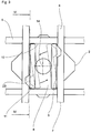
Figur 2 von unten, mit einer Halteeinrichtung bestehend aus zwei parallel und beabstandet zueinander verlaufenden Stegen, an denen jeweils eine nach außen abstehende Rastnase angearbeitet ist, - Figur 4
- den Verbindungskörper gemäß
Figur 1 , im Schnitt und - Figur 5
- die Vorrichtung gemäß
Figur 1 mit zwei parallel entlang der jeweiligen Aufnahmeöffnung verlaufenden Drahtsträngen zur Aufnahme von benachbarten Verbindungskörpem. - In den
Figuren 1 ,2 ,3 und4 ist eine Vorrichtung 1 abgebildet, durch die ein Verbindungskörper 2 als Bestandteil der Vorrichtung 1 zur Aufnahme von Gegenständen 3 lageorientiert und drehfest fixiert ist. Die in den Verbindungskörpern 2 eingesteckten Gegenstände 3, beispielsweise Werkstücke oder Werkzeuge, sollen zu Transport-, Lager- und Bearbeitungszwecken beschädigungsfrei durch die Verbindungskörper 2 abgestützt sein. - Die Vorrichtung 1 umfasst ein Kastenprofil 16, das aus vier senkrecht zueinander verlaufenden Rahmenteilen 15 gebildet ist, die an ihren jeweiligen freien Enden fest miteinander verbunden sind. Diese Kastenprofile 16 können Transporthilfen oder als Haltemittel für Werkstücke oder Werkzeuge aller Art verwendet werden.
- Darüberhinaus sind zwischen den Rahmenteilen 15 des Kastenprofils 16 eine Vielzahl von parallel und beabstandet zueinander verlaufenden Drahtsträngen 7 angeordnet, die in zwei unterschiedlichen Ebenen 5, 6 verlaufen und folglich ein mit einer Gitterstruktur versehenes Traggestell 4 bilden. Die parallel und beabstandet zueinander angeordneten Drahtstränge 7 liegen demnach in einer der Ebenen 5 oder 6. Die Drahtstränge 7 in den beiden Ebenen 5 und 6 sind in ihren Kreuzungspunkten fest miteinander verbunden, so dass zwischen den Drahtsträngen 7 der Ebenen 5, 6 eine rechteckförmige Aufnahmeöffnung 8 geschaffen ist. Benachbarte Drahtstränge 7 der oberen Ebene 5 bilden eine längere Kante 9 aus als in der unteren Ebene 6 angeordnete benachbarte Drahtstränge 7. Die durch benachbarte Drahtstränge 7 der oberen Ebene 5 definierte Kantenlänge der Längeren Kanten 9 ist mit der Variablen a und die durch benachbarte Drahtstränge 7 der unteren Ebene 6 definierte Kantenlänge der Kürzeren Kanten 10 ist mit der Variablen b als Bezugsgröße in
Figur 1 gekennzeichnet. - Die Verbindungskörper 2 weisen jeweils eine angeformte oder angearbeitete Halteeinrichtung 11 auf, die aus zwei parallel und beabstandet zueinander verlaufenden Stegen 21 gebildet ist. Der Abstand der beiden Stege 21 ist dabei von der Länge der kürzeren Kanten 10 der jeweiligen Aufnahmeöffnung 8 bestimmt und die Länge der Stege 21 ist an die längeren Kanten 9 der Aufnahmeöffnungen 8 angepasst, so dass durch die Anordnung und die Länge der Stege 21 die jeweiligen Verbindungskörper 2 lageorientiert in der jeweiligen Aufnahmeöffnung 8 gemäß
Figur 2 eingerastet werden können. - Um ein Herausfallen der Verbindungskörper 2 aus der jeweiligen Aufnahmeöffnung 8 zu verhindern, ist an den beiden Stegen 21 jeweils eine senkrecht nach außen abstehende Rastnase 23 angearbeitet oder angeformt, die im montierten Zustand des Verbindungskörpers 2 die Drahtstränge 7 der unteren Ebene 6 umgreift und an diesen nach Art einer Hinterschneidung anliegt.
- Die Verrastung der Rastnasen 23 an den Drahtsträngen 7 wird dadurch verbessert, dass zwischen jedem der Stege 21 und dem Boden des Verbindungskörpers 2 eine keil- oder V-förmig ausgestaltete Nut 22 eingearbeitet ist, durch die der Steg 21 geringfügig beweglich und federnd an dem Boden des Verbindungskörpers 2 gelagert ist. Die Rastnasen 23 sind dabei im Bereich der größten Ausdehnung der Nut 22 angeordnet. Die Nuten 22 verlaufen gegenläufig zueinander, so dass die Rastnasen somit diametral oder spiegelbildlich versetzt zueinander angeordnet sind.
- Der
Figur 5 ist die Anbringung von unmittelbar benachbart zueinander angeordneten Verbindungskörpern 2 zu entnehmen. Das Traggestell 4 umfasst zwei unmittelbar zueinander verlaufende Drahtstränge 7, die jeweils einer der Aufnahmeöffnungen 8 zugewandt sind. Folglich kann jeder Verbindungskörper 2 an einen unabhängigen Drahtstrang 7 angeklippst werden. - Insbesondere aus
Figur 4 ist ersichtlich, dass an jedem der Verbindungskörper 2 mindestens eine Haltenase 13 angeformt ist, die radial nach außen absteht. Die Haltenasen 13 sind vorzugsweise in den Eckbereichen der Verbindungskörper 2 angebracht, sind jeweils einem der Knotenpunkte der Drahtstränge 7 der unteren und oberen Ebene 5, 6 zugewandt und überragen die Drahtstränge 7 der oberen Ebene 5. Der Abstand zwischen den Haltenasen 13 und den Rastnasen 23 ist dabei derart bemessen, dass die von den Drahtsträngen 7 der oberen und unteren Ebene 5, 6 eingenommene Distanz überbrückt ist bzw. dass die Drahtstränge 7 der oberen und unteren Ebene 5, 6 zwischen den Haltenasen 13 und den Rastnasen 23 verspannt sind, so dass der Verbindungskörper 2 lageorientiert und drehfest in der jeweiligen Aufnahmeöffnung 8 eingesetzt ist.
Claims (8)
- Vorrichtung (1) zur Aufnahme und Arretierung von Gegenständen (3), beispielsweise Werkstücken oder Werkzeugen,- mit einem nach Art einer Gitterstruktur aufgebauten Traggestell (4), das aus parallel und beabstandet zueinander ausgerichteten Drahtsträngen (7) gebildet ist, durch die mindestens eine rechteckförmige Aufnahmeöffnung (8) geschaffen ist, wobei die parallel zueinander verlaufenden Drahtstränge (7) in jeweils einer Ebene 5, 6) angeordnet sind und wobei der Abstand (a) der Drahtstränge (7) der oberen Ebene (5) die Kantenlänge der Längeren Kanten (9) der Aufnahmeöffnung (8) bestimmt und der Abstand (b) der Drahtstränge (7) der unteren Ebene (6) die Kantenlänge der Kürzeren Kanten (10) der Aufnahmeöffrung (8) bestimmt,- und mit mindestens einem Verbindungskörper (2), der einen Boden aufweist, an dessen einer Stirnseite eine Halteeinrichtung (11) vorgesehen ist, die in eine der Aufnahmeöffnungen (8) des Traggestells (4) einsteckbar ist, und an dessen gegenüberliegenden Stirnseite eine oder mehrere Halte- oder Aufnahmeelemente (12) angebracht sind, durch die die Gegenstände (3) mit dem Verbindungskörper (2) und dem Traggestell (4) fixiert werden können,dadurch gekennzeichnet,
dass die Halteeinrichtung (11) des Verbindungskörpers (2) aus zwei parallel und beabstandet zueinander verlaufenden Stegen (21) gebildet ist, deren Abstand zueinander von der Länge (b) der kürzeren Kanten (10) der Aufnahmeöffnung (8) bestimmt ist, dass die Länge der beiden Stege (21) an die Länge (a) der längeren Kanten (9) der Aufnahmeöffnung (8) angepasst ist, dass zwischen den Stegen (21) und dem Boden des Verbindungskörpers (2) jeweils eine keil- oder V-förmige Nut (22) eingearbeitet ist, durch die die Stege (21) bereichsweise vom Boden des Verbindungskörpers (2) getrennt sind und dass an jedem der beiden Stege (21) im Bereich der größten Ausdehnung der Nut (22) eine senkrecht nach außen abstehende Rastnase (23) angearbeitet bzw. angeformt ist, die im montierten Zustand des Verbindungskörpers (2) die untere Ebene (6) der Drahtstränge (7) umgreift und dass die Rastnasen (23) der beiden Stege (21) diametral gegenüberliegend bzw. spiegelbildlich versetzt zueinander verlaufen. - Verbindungskörper (2), zur Anwendung in einer Vorrichtung (1) nach Anspruch 1, aufweisend einen Boden, an dessen einer Stirnseite eine Halteeinrichtung (11) vorgesehen ist und an dessen gegenüberliegenden Stirnseite mindestens ein Halte- oder Aufnahmeelement (12) zur Fixierung eines der Gegenstände (3) angebracht ist,
dadurch gekennzeichnet,
dass die Halteeinrichtung (11) aus zwei parallel und beabstandet zueinander angeordneten Stegen (21) besteht, dass die Stege (21) jeweils mittels einer keil- oder V-förmig ausgestalteten Nut (22) bereichsweise vom Boden des Verbindungskörpers (2) getrennt sind, dass jeweils im Bereich der größten Ausdehnung der Nut (22) eine senkrecht von dem Steg (21) nach außen abstehende Rastnase (23) ange-formt ist und dass die Rastnasen (23) der beiden Stege (21) diametral gegenüberliegend bzw. spiegelbildlich versetzt zueinander verlaufen. - Vorrichtung oder Verbindungskörper nach einem der Ansprüche 1 oder 2,
dadurch gekennzeichnet,
dass die Länge der Stege (21) und deren Abstand zueinander an die Innenkontur der Aufnahmeöffnung (8) angepasst ist und dass die Stege (21) im montierten Zustand des Verbindungskörpers (2) an den Drahtsträngen (7) der oberen und unteren Ebene (5, 6) der Aufnahmeöffnungen (8) anliegen. - Vorrichtung (1) oder Verbindungskörper (2) nach einem der vorgenannten Ansprüche,
dadurch gekennzeichnet,
dass an dem Verbindungskörper (2) mindestens eine radial nach außen abstehende Haltenase (13) angeformt ist, die die obere Ebene (5) der Drahtstränge (7) übergreift und dass der Abstand zwischen der Haltenase (13) und den Rastnasen (23) der beiden Stege (21) an die Durchmesser der Drahtstränge 7 der oberen und unteren Ebene (5, 6) angepasst ist. - Vorrichtung (1) oder Verbindungskörper (2) nach Anspruch 4,
dadurch gekennzeichnet,
dass der Verbindungskörper (2) mittels der Haltenase (13) und der Rastnasen (23) zwischen den beiden Ebenen (5, 6) der Aufnahmeöffnung (8) verspannt gehalten ist. - Vorrichtung (1) oder Verbindungskörper (2) nach einem der vorgenannten Ansprüche,
dadurch gekennzeichnet,
dass die Rastnasen (23) der beiden Stege (21) in die jeweilige Aufnahmeöffnung (8) einklippsbar sind und nach Art einer Hinterschneidung an der unteren Ebene (6) der Aufnahmeöffnung (8) gehalten sind. - Vorrichtung (1) oder Verbindungskörper (2) nach einem der vorgenannten Ansprüche,
dadurch gekennzeichnet,
dass der Verbindungskörper (2) einschließlich der Stege (21) aus einem Kunststoff-Werkstoff hergestellt ist, und dass durch die keil- oder V-förmige Nut (22) zwischen dem Boden des Verbindungskörpers (2) und dem jeweiligen Steg (21) eine federnde Beweglichkeit der jeweiligen Stege (21) gegeben ist. - Vorrichtung (1) nach einem der vorgenannten Ansprüche,
dadurch gekennzeichnet,
dass zwischen zwei benachbarten Aufnahmeöffnungen (8) zwei Drahtstränge (7) in der oberen und/oder unteren Ebene (5 und/oder 6) angeordnet sind, die aneinander anliegen oder geringfügig beabstandet sind.
Priority Applications (1)
| Application Number | Priority Date | Filing Date | Title |
|---|---|---|---|
| EP13188284.7A EP2860126B1 (de) | 2013-10-11 | 2013-10-11 | Vorrichtung zum Halten von Gegenständen und zugehöriger Verbindungskörper |
Applications Claiming Priority (1)
| Application Number | Priority Date | Filing Date | Title |
|---|---|---|---|
| EP13188284.7A EP2860126B1 (de) | 2013-10-11 | 2013-10-11 | Vorrichtung zum Halten von Gegenständen und zugehöriger Verbindungskörper |
Publications (2)
| Publication Number | Publication Date |
|---|---|
| EP2860126A1 EP2860126A1 (de) | 2015-04-15 |
| EP2860126B1 true EP2860126B1 (de) | 2016-06-29 |
Family
ID=49378104
Family Applications (1)
| Application Number | Title | Priority Date | Filing Date |
|---|---|---|---|
| EP13188284.7A Not-in-force EP2860126B1 (de) | 2013-10-11 | 2013-10-11 | Vorrichtung zum Halten von Gegenständen und zugehöriger Verbindungskörper |
Country Status (1)
| Country | Link |
|---|---|
| EP (1) | EP2860126B1 (de) |
Families Citing this family (10)
| Publication number | Priority date | Publication date | Assignee | Title |
|---|---|---|---|---|
| AT14852U1 (de) * | 2015-07-30 | 2016-07-15 | Fries Planungs- Und Marketinggesellschaft M B H | Trägeranordnung |
| EP3330196B1 (de) * | 2016-12-01 | 2019-05-01 | ALWA GmbH & Co. KG Konstruktion & Formenbau | Vorrichtung zur aufnahme von gegenständen und zugehöriger verbindungskörper |
| EP3480128B1 (de) | 2017-11-06 | 2020-03-04 | ALWA GmbH & Co. KG Konstruktion & Formenbau | Vorrichtung zur aufnahme und zur arretierung von gegenständen und zugehöriges traggestell |
| GB201718954D0 (en) | 2017-11-16 | 2018-01-03 | Chep Technology Pty Ltd | Support Module |
| EP3608246B1 (de) * | 2018-08-08 | 2021-05-12 | ALWA GmbH & Co. KG Konstruktion & Formenbau | Vorrichtung zur halterung von gegenständen |
| CN109367968A (zh) * | 2018-12-05 | 2019-02-22 | 盐城远大金属科技有限公司 | 一种凸轮专用工装 |
| USD951580S1 (en) | 2019-05-15 | 2022-05-10 | Chep Technology Pty Limited | Part for a pallet |
| USD945735S1 (en) | 2019-05-15 | 2022-03-08 | Chep Technology Pty Limited | Part for a pallet |
| USD949509S1 (en) | 2019-05-15 | 2022-04-19 | Chep Technology Pty Limited | Part for a pallet |
| DE102022122236B4 (de) | 2022-09-02 | 2024-05-23 | Aesculap Ag | Befestigungsklammer zur Anbringung von Haltern für medizinische Instrumente in einem Sterilisationssiebkorb und Anordnung mit einem Sterilisationssiebkorb und einer Befestigungsklammer |
Family Cites Families (3)
| Publication number | Priority date | Publication date | Assignee | Title |
|---|---|---|---|---|
| DE8908551U1 (de) * | 1989-07-13 | 1989-11-02 | Bloksma Metallwarenfabrik Gmbh, 7064 Remshalden | Aufbewahrungsvorrichtung für Werkstücke o.dgl. Gegenstände |
| EP2570234B1 (de) | 2011-09-13 | 2013-11-20 | ALWA GmbH & Co. KG Konstruktion & Formenbau | Aufnahmeträger |
| DE202012103711U1 (de) * | 2012-09-27 | 2012-11-15 | Ingo Zell | Trägerplatte eines Werkstückträgersystems sowie Werkstückträgersystem |
-
2013
- 2013-10-11 EP EP13188284.7A patent/EP2860126B1/de not_active Not-in-force
Also Published As
| Publication number | Publication date |
|---|---|
| EP2860126A1 (de) | 2015-04-15 |
Similar Documents
| Publication | Publication Date | Title |
|---|---|---|
| EP2860126A1 (de) | Vorrichtung zur Aufnahme und zum Halten von Gegenständen und zugehöriger Verbindungskörper | |
| EP0918943B1 (de) | Leitungshalter mit aufnahmebereich zum beiderseitigen aufstecken auf einen gewindebolzen | |
| EP2952439B1 (de) | Verbund von Aufnahmekörpern | |
| EP2860127B1 (de) | Vorrichtung zum Halten von Gegenständen und zugehöriger Verbindungskörper | |
| EP3330196B1 (de) | Vorrichtung zur aufnahme von gegenständen und zugehöriger verbindungskörper | |
| EP2410187A1 (de) | Schutzgitter-Anordnung für Lüfter | |
| EP3480128A1 (de) | Vorrichtung zur aufnahme und zur arretierung von gegenständen | |
| DE102008023189B4 (de) | Halteelement aus Kunststoff zur Halterung eines länglichen Gegenstands | |
| EP2261544B1 (de) | Befestigungsschelle | |
| EP3633131A1 (de) | Rahmenelement | |
| DE102021126788A1 (de) | Radschutzvorrichtung für ein Zweirad | |
| EP2177694B1 (de) | Zaunklammer zur Befestigung eines Zaungitters an einem Pfosten | |
| DE202013005582U1 (de) | System umfassend ein Trägerbauteil | |
| DE202014102215U1 (de) | Modularer Werkstückträger | |
| DE102014103651A1 (de) | Clip aus Kunststoff zur Befestigung eines Gegenstands an einem Bolzen | |
| DE202005010186U1 (de) | Halteeinrichtung sowie Halteelement hierfür | |
| WO2017092776A1 (de) | Walzenbürstengrundkörper und walzenbürste | |
| AT515601B1 (de) | System zur Aufnahme von Lichtmodulen sowie Verfahren für dessen Herstellung | |
| DE102011108725B4 (de) | Werkstückträger zum Tragen von Werkstücken | |
| DE102009007428B3 (de) | Verbindungselement zur fluchtenden Verbindung benachbarter Gittermatten und damit gebauter Zaun | |
| EP3615815B1 (de) | Clip zum abstützen eines ersten bauteils an einem zweiten bauteil | |
| EP2821285B1 (de) | Verbindungselement zur Befestigung von Zierleisten auf einem Stoßfänger | |
| DE202010010316U1 (de) | Befestigungselement zum Halten eines Wischmops an einem Stiel | |
| EP3608246B1 (de) | Vorrichtung zur halterung von gegenständen | |
| EP2754762A1 (de) | Entwässerungs- und/oder Flüssigkeitsspeichervorrichtung zum Einbau ins Erdreich |
Legal Events
| Date | Code | Title | Description |
|---|---|---|---|
| PUAI | Public reference made under article 153(3) epc to a published international application that has entered the european phase |
Free format text: ORIGINAL CODE: 0009012 |
|
| 17P | Request for examination filed |
Effective date: 20131011 |
|
| AK | Designated contracting states |
Kind code of ref document: A1 Designated state(s): AL AT BE BG CH CY CZ DE DK EE ES FI FR GB GR HR HU IE IS IT LI LT LU LV MC MK MT NL NO PL PT RO RS SE SI SK SM TR |
|
| AX | Request for extension of the european patent |
Extension state: BA ME |
|
| R17P | Request for examination filed (corrected) |
Effective date: 20150910 |
|
| RBV | Designated contracting states (corrected) |
Designated state(s): AL AT BE BG CH CY CZ DE DK EE ES FI FR GB GR HR HU IE IS IT LI LT LU LV MC MK MT NL NO PL PT RO RS SE SI SK SM TR |
|
| GRAP | Despatch of communication of intention to grant a patent |
Free format text: ORIGINAL CODE: EPIDOSNIGR1 |
|
| RIC1 | Information provided on ipc code assigned before grant |
Ipc: F16B 21/08 20060101ALN20160119BHEP Ipc: B65D 19/44 20060101AFI20160119BHEP Ipc: B23Q 7/14 20060101ALN20160119BHEP |
|
| INTG | Intention to grant announced |
Effective date: 20160210 |
|
| GRAS | Grant fee paid |
Free format text: ORIGINAL CODE: EPIDOSNIGR3 |
|
| GRAA | (expected) grant |
Free format text: ORIGINAL CODE: 0009210 |
|
| AK | Designated contracting states |
Kind code of ref document: B1 Designated state(s): AL AT BE BG CH CY CZ DE DK EE ES FI FR GB GR HR HU IE IS IT LI LT LU LV MC MK MT NL NO PL PT RO RS SE SI SK SM TR |
|
| REG | Reference to a national code |
Ref country code: GB Ref legal event code: FG4D Free format text: NOT ENGLISH |
|
| REG | Reference to a national code |
Ref country code: CH Ref legal event code: EP |
|
| REG | Reference to a national code |
Ref country code: AT Ref legal event code: REF Ref document number: 808897 Country of ref document: AT Kind code of ref document: T Effective date: 20160715 |
|
| REG | Reference to a national code |
Ref country code: IE Ref legal event code: FG4D Free format text: LANGUAGE OF EP DOCUMENT: GERMAN |
|
| REG | Reference to a national code |
Ref country code: DE Ref legal event code: R096 Ref document number: 502013003521 Country of ref document: DE |
|
| REG | Reference to a national code |
Ref country code: LT Ref legal event code: MG4D Ref country code: FR Ref legal event code: PLFP Year of fee payment: 4 |
|
| PG25 | Lapsed in a contracting state [announced via postgrant information from national office to epo] |
Ref country code: LT Free format text: LAPSE BECAUSE OF FAILURE TO SUBMIT A TRANSLATION OF THE DESCRIPTION OR TO PAY THE FEE WITHIN THE PRESCRIBED TIME-LIMIT Effective date: 20160629 Ref country code: FI Free format text: LAPSE BECAUSE OF FAILURE TO SUBMIT A TRANSLATION OF THE DESCRIPTION OR TO PAY THE FEE WITHIN THE PRESCRIBED TIME-LIMIT Effective date: 20160629 Ref country code: NO Free format text: LAPSE BECAUSE OF FAILURE TO SUBMIT A TRANSLATION OF THE DESCRIPTION OR TO PAY THE FEE WITHIN THE PRESCRIBED TIME-LIMIT Effective date: 20160929 |
|
| REG | Reference to a national code |
Ref country code: NL Ref legal event code: MP Effective date: 20160629 |
|
| PG25 | Lapsed in a contracting state [announced via postgrant information from national office to epo] |
Ref country code: RS Free format text: LAPSE BECAUSE OF FAILURE TO SUBMIT A TRANSLATION OF THE DESCRIPTION OR TO PAY THE FEE WITHIN THE PRESCRIBED TIME-LIMIT Effective date: 20160629 Ref country code: GR Free format text: LAPSE BECAUSE OF FAILURE TO SUBMIT A TRANSLATION OF THE DESCRIPTION OR TO PAY THE FEE WITHIN THE PRESCRIBED TIME-LIMIT Effective date: 20160930 Ref country code: NL Free format text: LAPSE BECAUSE OF FAILURE TO SUBMIT A TRANSLATION OF THE DESCRIPTION OR TO PAY THE FEE WITHIN THE PRESCRIBED TIME-LIMIT Effective date: 20160629 Ref country code: LV Free format text: LAPSE BECAUSE OF FAILURE TO SUBMIT A TRANSLATION OF THE DESCRIPTION OR TO PAY THE FEE WITHIN THE PRESCRIBED TIME-LIMIT Effective date: 20160629 Ref country code: HR Free format text: LAPSE BECAUSE OF FAILURE TO SUBMIT A TRANSLATION OF THE DESCRIPTION OR TO PAY THE FEE WITHIN THE PRESCRIBED TIME-LIMIT Effective date: 20160629 Ref country code: SE Free format text: LAPSE BECAUSE OF FAILURE TO SUBMIT A TRANSLATION OF THE DESCRIPTION OR TO PAY THE FEE WITHIN THE PRESCRIBED TIME-LIMIT Effective date: 20160629 |
|
| PG25 | Lapsed in a contracting state [announced via postgrant information from national office to epo] |
Ref country code: IS Free format text: LAPSE BECAUSE OF FAILURE TO SUBMIT A TRANSLATION OF THE DESCRIPTION OR TO PAY THE FEE WITHIN THE PRESCRIBED TIME-LIMIT Effective date: 20161029 Ref country code: EE Free format text: LAPSE BECAUSE OF FAILURE TO SUBMIT A TRANSLATION OF THE DESCRIPTION OR TO PAY THE FEE WITHIN THE PRESCRIBED TIME-LIMIT Effective date: 20160629 Ref country code: SK Free format text: LAPSE BECAUSE OF FAILURE TO SUBMIT A TRANSLATION OF THE DESCRIPTION OR TO PAY THE FEE WITHIN THE PRESCRIBED TIME-LIMIT Effective date: 20160629 Ref country code: RO Free format text: LAPSE BECAUSE OF FAILURE TO SUBMIT A TRANSLATION OF THE DESCRIPTION OR TO PAY THE FEE WITHIN THE PRESCRIBED TIME-LIMIT Effective date: 20160629 Ref country code: CZ Free format text: LAPSE BECAUSE OF FAILURE TO SUBMIT A TRANSLATION OF THE DESCRIPTION OR TO PAY THE FEE WITHIN THE PRESCRIBED TIME-LIMIT Effective date: 20160629 |
|
| PG25 | Lapsed in a contracting state [announced via postgrant information from national office to epo] |
Ref country code: PT Free format text: LAPSE BECAUSE OF FAILURE TO SUBMIT A TRANSLATION OF THE DESCRIPTION OR TO PAY THE FEE WITHIN THE PRESCRIBED TIME-LIMIT Effective date: 20161031 Ref country code: SM Free format text: LAPSE BECAUSE OF FAILURE TO SUBMIT A TRANSLATION OF THE DESCRIPTION OR TO PAY THE FEE WITHIN THE PRESCRIBED TIME-LIMIT Effective date: 20160629 Ref country code: BE Free format text: LAPSE BECAUSE OF NON-PAYMENT OF DUE FEES Effective date: 20161031 Ref country code: ES Free format text: LAPSE BECAUSE OF FAILURE TO SUBMIT A TRANSLATION OF THE DESCRIPTION OR TO PAY THE FEE WITHIN THE PRESCRIBED TIME-LIMIT Effective date: 20160629 Ref country code: PL Free format text: LAPSE BECAUSE OF FAILURE TO SUBMIT A TRANSLATION OF THE DESCRIPTION OR TO PAY THE FEE WITHIN THE PRESCRIBED TIME-LIMIT Effective date: 20160629 |
|
| REG | Reference to a national code |
Ref country code: DE Ref legal event code: R097 Ref document number: 502013003521 Country of ref document: DE |
|
| PG25 | Lapsed in a contracting state [announced via postgrant information from national office to epo] |
Ref country code: DK Free format text: LAPSE BECAUSE OF FAILURE TO SUBMIT A TRANSLATION OF THE DESCRIPTION OR TO PAY THE FEE WITHIN THE PRESCRIBED TIME-LIMIT Effective date: 20160629 |
|
| REG | Reference to a national code |
Ref country code: CH Ref legal event code: PL |
|
| 26N | No opposition filed |
Effective date: 20170330 |
|
| PLBE | No opposition filed within time limit |
Free format text: ORIGINAL CODE: 0009261 |
|
| STAA | Information on the status of an ep patent application or granted ep patent |
Free format text: STATUS: NO OPPOSITION FILED WITHIN TIME LIMIT |
|
| REG | Reference to a national code |
Ref country code: IE Ref legal event code: MM4A |
|
| PG25 | Lapsed in a contracting state [announced via postgrant information from national office to epo] |
Ref country code: CH Free format text: LAPSE BECAUSE OF NON-PAYMENT OF DUE FEES Effective date: 20161031 Ref country code: LI Free format text: LAPSE BECAUSE OF NON-PAYMENT OF DUE FEES Effective date: 20161031 |
|
| PG25 | Lapsed in a contracting state [announced via postgrant information from national office to epo] |
Ref country code: LU Free format text: LAPSE BECAUSE OF NON-PAYMENT OF DUE FEES Effective date: 20161011 Ref country code: SI Free format text: LAPSE BECAUSE OF FAILURE TO SUBMIT A TRANSLATION OF THE DESCRIPTION OR TO PAY THE FEE WITHIN THE PRESCRIBED TIME-LIMIT Effective date: 20160629 Ref country code: BG Free format text: LAPSE BECAUSE OF FAILURE TO SUBMIT A TRANSLATION OF THE DESCRIPTION OR TO PAY THE FEE WITHIN THE PRESCRIBED TIME-LIMIT Effective date: 20160929 |
|
| REG | Reference to a national code |
Ref country code: FR Ref legal event code: PLFP Year of fee payment: 5 |
|
| PG25 | Lapsed in a contracting state [announced via postgrant information from national office to epo] |
Ref country code: IE Free format text: LAPSE BECAUSE OF NON-PAYMENT OF DUE FEES Effective date: 20161011 |
|
| REG | Reference to a national code |
Ref country code: BE Ref legal event code: MM Effective date: 20161031 |
|
| PG25 | Lapsed in a contracting state [announced via postgrant information from national office to epo] |
Ref country code: HU Free format text: LAPSE BECAUSE OF FAILURE TO SUBMIT A TRANSLATION OF THE DESCRIPTION OR TO PAY THE FEE WITHIN THE PRESCRIBED TIME-LIMIT; INVALID AB INITIO Effective date: 20131011 |
|
| GBPC | Gb: european patent ceased through non-payment of renewal fee |
Effective date: 20171011 |
|
| PG25 | Lapsed in a contracting state [announced via postgrant information from national office to epo] |
Ref country code: MC Free format text: LAPSE BECAUSE OF FAILURE TO SUBMIT A TRANSLATION OF THE DESCRIPTION OR TO PAY THE FEE WITHIN THE PRESCRIBED TIME-LIMIT Effective date: 20160629 Ref country code: MT Free format text: LAPSE BECAUSE OF FAILURE TO SUBMIT A TRANSLATION OF THE DESCRIPTION OR TO PAY THE FEE WITHIN THE PRESCRIBED TIME-LIMIT Effective date: 20160629 Ref country code: MK Free format text: LAPSE BECAUSE OF FAILURE TO SUBMIT A TRANSLATION OF THE DESCRIPTION OR TO PAY THE FEE WITHIN THE PRESCRIBED TIME-LIMIT Effective date: 20160629 Ref country code: CY Free format text: LAPSE BECAUSE OF FAILURE TO SUBMIT A TRANSLATION OF THE DESCRIPTION OR TO PAY THE FEE WITHIN THE PRESCRIBED TIME-LIMIT Effective date: 20160629 |
|
| PG25 | Lapsed in a contracting state [announced via postgrant information from national office to epo] |
Ref country code: GB Free format text: LAPSE BECAUSE OF NON-PAYMENT OF DUE FEES Effective date: 20171011 |
|
| REG | Reference to a national code |
Ref country code: FR Ref legal event code: PLFP Year of fee payment: 6 |
|
| PG25 | Lapsed in a contracting state [announced via postgrant information from national office to epo] |
Ref country code: AL Free format text: LAPSE BECAUSE OF FAILURE TO SUBMIT A TRANSLATION OF THE DESCRIPTION OR TO PAY THE FEE WITHIN THE PRESCRIBED TIME-LIMIT Effective date: 20160629 Ref country code: TR Free format text: LAPSE BECAUSE OF FAILURE TO SUBMIT A TRANSLATION OF THE DESCRIPTION OR TO PAY THE FEE WITHIN THE PRESCRIBED TIME-LIMIT Effective date: 20160629 |
|
| PGFP | Annual fee paid to national office [announced via postgrant information from national office to epo] |
Ref country code: GB Payment date: 20181029 Year of fee payment: 10 |
|
| PG25 | Lapsed in a contracting state [announced via postgrant information from national office to epo] |
Ref country code: FR Free format text: LAPSE BECAUSE OF NON-PAYMENT OF DUE FEES Effective date: 20191031 |
|
| REG | Reference to a national code |
Ref country code: DE Ref legal event code: R082 Ref document number: 502013003521 Country of ref document: DE Representative=s name: GEITZ PATENTANWAELTE PARTG MBB, DE Ref country code: DE Ref legal event code: R082 Ref document number: 502013003521 Country of ref document: DE Representative=s name: GEITZ TRUCKENMUELLER LUCHT CHRIST PATENTANWAEL, DE |
|
| PGFP | Annual fee paid to national office [announced via postgrant information from national office to epo] |
Ref country code: IT Payment date: 20221031 Year of fee payment: 10 Ref country code: DE Payment date: 20221020 Year of fee payment: 10 Ref country code: AT Payment date: 20221018 Year of fee payment: 10 |
|
| P01 | Opt-out of the competence of the unified patent court (upc) registered |
Effective date: 20230512 |
|
| REG | Reference to a national code |
Ref country code: DE Ref legal event code: R119 Ref document number: 502013003521 Country of ref document: DE |
|
| REG | Reference to a national code |
Ref country code: AT Ref legal event code: MM01 Ref document number: 808897 Country of ref document: AT Kind code of ref document: T Effective date: 20231011 |
|
| PG25 | Lapsed in a contracting state [announced via postgrant information from national office to epo] |
Ref country code: AT Free format text: LAPSE BECAUSE OF NON-PAYMENT OF DUE FEES Effective date: 20231011 |
|
| PG25 | Lapsed in a contracting state [announced via postgrant information from national office to epo] |
Ref country code: DE Free format text: LAPSE BECAUSE OF NON-PAYMENT OF DUE FEES Effective date: 20240501 Ref country code: AT Free format text: LAPSE BECAUSE OF NON-PAYMENT OF DUE FEES Effective date: 20231011 |
|
| PG25 | Lapsed in a contracting state [announced via postgrant information from national office to epo] |
Ref country code: IT Free format text: LAPSE BECAUSE OF NON-PAYMENT OF DUE FEES Effective date: 20231011 |
|
| PG25 | Lapsed in a contracting state [announced via postgrant information from national office to epo] |
Ref country code: IT Free format text: LAPSE BECAUSE OF NON-PAYMENT OF DUE FEES Effective date: 20231011 |