EP2860112B1 - Verfahren und Vorrichtung zur Erkennung von Eisbildung an Flugzeugen - Google Patents
Verfahren und Vorrichtung zur Erkennung von Eisbildung an Flugzeugen Download PDFInfo
- Publication number
- EP2860112B1 EP2860112B1 EP14181926.8A EP14181926A EP2860112B1 EP 2860112 B1 EP2860112 B1 EP 2860112B1 EP 14181926 A EP14181926 A EP 14181926A EP 2860112 B1 EP2860112 B1 EP 2860112B1
- Authority
- EP
- European Patent Office
- Prior art keywords
- material layer
- ice
- pyroelectric material
- aircraft
- detector
- Prior art date
- Legal status (The legal status is an assumption and is not a legal conclusion. Google has not performed a legal analysis and makes no representation as to the accuracy of the status listed.)
- Active
Links
Images



Classifications
-
- G—PHYSICS
- G01—MEASURING; TESTING
- G01K—MEASURING TEMPERATURE; MEASURING QUANTITY OF HEAT; THERMALLY-SENSITIVE ELEMENTS NOT OTHERWISE PROVIDED FOR
- G01K7/00—Measuring temperature based on the use of electric or magnetic elements directly sensitive to heat ; Power supply therefor, e.g. using thermoelectric elements
- G01K7/003—Measuring temperature based on the use of electric or magnetic elements directly sensitive to heat ; Power supply therefor, e.g. using thermoelectric elements using pyroelectric elements
-
- B—PERFORMING OPERATIONS; TRANSPORTING
- B64—AIRCRAFT; AVIATION; COSMONAUTICS
- B64D—EQUIPMENT FOR FITTING IN OR TO AIRCRAFT; FLIGHT SUITS; PARACHUTES; ARRANGEMENT OR MOUNTING OF POWER PLANTS OR PROPULSION TRANSMISSIONS IN AIRCRAFT
- B64D15/00—De-icing or preventing icing on exterior surfaces of aircraft
- B64D15/20—Means for detecting icing or initiating de-icing
-
- G—PHYSICS
- G01—MEASURING; TESTING
- G01K—MEASURING TEMPERATURE; MEASURING QUANTITY OF HEAT; THERMALLY-SENSITIVE ELEMENTS NOT OTHERWISE PROVIDED FOR
- G01K13/00—Thermometers specially adapted for specific purposes
- G01K13/04—Thermometers specially adapted for specific purposes for measuring temperature of moving solid bodies
-
- G—PHYSICS
- G01—MEASURING; TESTING
- G01K—MEASURING TEMPERATURE; MEASURING QUANTITY OF HEAT; THERMALLY-SENSITIVE ELEMENTS NOT OTHERWISE PROVIDED FOR
- G01K7/00—Measuring temperature based on the use of electric or magnetic elements directly sensitive to heat ; Power supply therefor, e.g. using thermoelectric elements
-
- G—PHYSICS
- G08—SIGNALLING
- G08B—SIGNALLING SYSTEMS, e.g. PERSONAL CALLING SYSTEMS; ORDER TELEGRAPHS; ALARM SYSTEMS
- G08B19/00—Alarms responsive to two or more different undesired or abnormal conditions, e.g. burglary and fire, abnormal temperature and abnormal rate of flow
- G08B19/02—Alarm responsive to formation or anticipated formation of ice
Definitions
- This disclosure relates to methods and apparatus for detecting ice formation on aircraft and, in particular, to ice detectors comprising a pyroelectric material.
- False negative readings can be particularly common when flying an aircraft at a temperature near the freezing point of water, such as about -2.78-0°C (27-32°F), and an altitude of about 457.2-3,962.4 meters (1500-13,000 feet). Under such conditions, ice can form on the leading edge of an aircraft's wing or another critical flight surface prior to ice formation on an ice detector disposed in a typical location on the aircraft, such as on the forward fuselage section of the aircraft.
- DE102012208653 discloses a pyroelectric material layer disposed on at least a portion of a probe surface on an aircraft surface.
- apparatus comprising ice detectors are described herein which may provide one or more advantages over previous ice detectors.
- an ice detector described herein can detect ice formation on an aircraft surface under atmospheric conditions at which other ice detectors cannot detect ice formation on the aircraft surface.
- an ice detector described herein can detect ice formation at any temperature, pressure, and moisture level included in an icing envelope described by 14 CFR 25, Appendix C (1-1-12 Edition). Therefore, in some cases, an ice detector described herein can provide early detection of ice formation on a critical flight surface of the aircraft, thereby reducing the likelihood of a hazardous false negative reading.
- an ice detector described herein can achieve one or more of the foregoing advantages without the need for a substantial redesign or retrofit of the aircraft.
- an ice detector described herein can be coupled to an aircraft without substantially perturbing the aircraft's aerodynamic properties.
- an ice detector described herein can be coupled to the exterior surface or skin of the front fuselage section of the aircraft, including in place of an existing ice detector disposed in this location. Therefore, in some implementations, an ice detector described herein can be used to retrofit an aircraft such as a commercial jetliner or other airplane in a cost effective and/or efficient manner. According to the invention, the ice detector of claim 11 is provided.
- An ice detector described herein comprises a probe surface and a pyroelectric material layer disposed on at least a portion of the probe surface.
- the pyroelectric material layer is directly disposed on the probe surface.
- one or more additional layers are disposed between the probe surface and the pyroelectric material layer.
- an ice detector described herein further comprises an adhesive material layer disposed between the probe surface and the pyroelectric material layer.
- the probe surface of an ice detector described herein is a vibrating probe surface such as an ultrasonic probe surface.
- the probe surface is part of a magnetostrictive detector architecture.
- the pyroelectric material layer of an ice detector described herein in some implementations, is a crystalline layer. In other instances, the pyroelectric material layer is a quasi-amorphous layer. Moreover, the pyroelectric material layer of an ice detector described herein can be a substantially continuous layer or a tiled layer. Further, in some implementations, a pyroelectric material layer of an ice detector described herein can comprise or be formed from an inorganic material such as a ceramic material, an organic material such as a polymeric material, or a combination thereof.
- a surface of the pyroelectric material layer of an ice detector described herein exhibits a local freezing point of water that is greater than the local freezing point of water exhibited by the probe surface of the ice detector under the same conditions. Further, the water can be supercooled liquid water. According to the invention, the method of claim 1 is provided. In some cases, for example, a method described herein can be used to detect the formation of ice on a noncritical surface of the aircraft prior to the formation of ice on a critical flight surface of the aircraft, thereby reducing the likelihood of a false negative reading.
- a method described herein can be used to provide an early warning of the presence of potentially hazardous flight conditions, such as conditions within an icing envelope described by 14 CFR 25, Appendix C (1-1-12 Edition).
- the method of detecting ice formation on an aircraft described herein comprises disposing an ice detector described herein on an exterior surface of the aircraft and generating a charge on a surface of the pyroelectric material layer of the ice detector to alter the local freezing point of water on the surface of the pyroelectric material layer.
- the local freezing point of water on the surface of the pyroelectric material layer is increased.
- the water can be supercooled liquid water.
- a method described herein further comprises providing a signal in response to the formation of ice on the surface of the pyroelectric material layer of the ice detector.
- the local freezing point of water on the surface of the pyroelectric material layer is greater than the local freezing point of water on one or more flight surfaces of the aircraft.
- the local freezing point of water on the surface of the pyroelectric material layer is greater than the local freezing point of water on a wing leading edge, an empennage leading edge, or an engine inlet leading edge of the aircraft.
- a method described herein can be used to identify the presence of icing conditions prior to the formation of ice on one or more critical flight surfaces, including in real-time while the aircraft is in flight.
- the phrase "up to” is used in connection with an amount or quantity, it is to be understood that the amount is at least a detectable amount or quantity.
- a material present in an amount “up to” a specified amount can be present from a detectable amount and up to and including the specified amount.
- Ice detectors are described herein. Ice detectors described herein can be used to detect the presence or absence of ice formation on an aircraft, including an aircraft in flight.
- ice from two different sources can be present on or near an aircraft in flight, particularly during flight in or near a cloud.
- One type of ice consists of ice formed by an "icing" process wherein supercooled liquid water nucleates or condenses on an aircraft surface and then freezes on the aircraft surface. The nucleation or condensation of the supercooled liquid water can immediately precede or occur substantially simultaneously with the freezing process. Additionally, the supercooled liquid water can be supercooled liquid water present in or near a cloud.
- a second type of ice that can be present on or near an aircraft in flight consists of ice that already exists in the aircraft's external environment as solid ice.
- this type of ice can be present in or near a cloud as suspended ice particles or ice crystals.
- Ice detectors described herein can be used particularly to detect the presence or absence of ice deposited on an aircraft surface by an icing process described above, as opposed to ice that may be present as suspended ice particles.
- ice detectors described herein are so-called “accretion” or "accumulation"-type ice detectors operable to detect the accumulation of ice due to one or more icing events.
- ice detectors described herein are not limited to ice accretion or ice accumulation detectors. Instead, ice detectors described herein can also comprise other detector architectures or structures. An ice detector described herein can include any ice detection structure not inconsistent with the objectives of the present disclosure, as described further herein below.
- Appendix C icing conditions or “Appendix C icing envelopes”
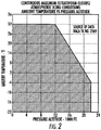
- Appendix C icing conditions or icing envelopes can include “continuous maximum icing” conditions, “intermittent maximum icing” conditions, or “takeoff maximum icing” conditions.
- Continuous maximum icing refers to the maximum continuous intensity of atmospheric icing conditions and is defined by the variables of the cloud liquid water content, the mean effective diameter of the cloud droplets, the ambient air temperature, and the interrelationship of these three variables, as shown in FIG. 1 , which corresponds to a figure published in Appendix C.
- FIG. 2 the limiting icing envelope in terms of altitude and temperature is given in FIG. 2 .
- the interrelationship of cloud liquid water content with drop diameter and altitude is determined from FIGS. 1 and 2 .
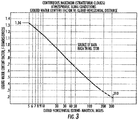
- the cloud liquid water content for continuous maximum icing conditions of a horizontal extent (other than 17.4 nautical miles) is determined by the value of the liquid water content of FIG. 1 , multiplied by the appropriate factor from FIG. 3 .
- FIGS. 2 and 3 also correspond to figures published in Appendix C.
- intermittent maximum icing refers to the intermittent maximum intensity of atmospheric icing conditions and is defined by the variables of the cloud liquid water content, the mean effective diameter of the cloud droplets, the ambient air temperature, and the interrelationship of these three variables, as shown in FIG. 4 , which corresponds to a figure published in Appendix C.
- the limiting icing envelope in terms of altitude and temperature is given in FIG. 5 .
- the interrelationship of cloud liquid water content with drop diameter and altitude is determined from FIGS. 4 and 5 .
- the cloud liquid water content for intermittent maximum icing conditions of a horizontal extent is determined by the value of the cloud liquid water content of FIG. 4 multiplied by the appropriate factor in FIG. 6 .
- FIGS. 5 and 6 also correspond to figures published in Appendix C.
- takeoff maximum icing refers to the maximum intensity of atmospheric icing conditions for takeoff and is defined by the cloud liquid water content of 0,35 g/m 3 , the mean effective diameter of the cloud droplets of 20 microns ( ⁇ m), and the ambient air temperature at ground level minus 9 degrees.
- the takeoff maximum icing conditions extend from ground level to a height of 457.2 meters (1500 feet) above the level of the takeoff surface.
- One embodiment of the present disclosure is to provide ice detectors that, in some implementations, can more accurately detect the presence or absence of an icing event on an aircraft, including when the aircraft is operated in Appendix C icing conditions or Appendix C icing envelopes, including those described in FIGS. 1-6 .
- some prior ice detectors provide false negative readings under some Appendix C icing conditions or icing envelopes, particularly when the ice detector is positioned on or near the forward fuselage of the aircraft. For example, FIG.
- FIG. 7 illustrates some conditions within an Appendix C icing envelope in which ice can form on a wing leading edge of an aircraft prior to ice forming on a prior art ice detector positioned on the forward fuselage of the aircraft (and thus prior to detection of ice by the prior art ice detector).
- the plot of FIG. 7 assumes that the prior art ice detector is a magnetostrictive accretion-type ice detector such as a Goodrich 0781LH1 ice detector.
- icing envelope (1100) is defined in terms of altitude and temperature.
- the solid line (1200) marks the conditions above which ice will not form on a prior art accretion-type ice detector positioned at the forward fuselage of an aircraft in flight. Below the solid line (1200), ice will form on the prior art ice detector, and the prior art ice detector will properly detect an icing event, giving a "true positive” reading. Thus, solid line (1200) defines a true positive detection region (1110) within the icing envelope (1100).
- the dashed line (1300) in FIG. 7 marks the conditions above which ice will not form on the leading edge of a typical wing of an aircraft, such as an aircraft's mid/inboard wing leading edge. Below the dashed line (1300), ice will form on the wing leading edge. Therefore, the solid line (1200) and the dashed line (1300) define a false negative detection region (1120) within the icing envelope (1100) in which a prior art ice detector positioned at the forward fuselage of the aircraft will incorrectly indicate the absence of an icing event on the wing leading edge. In contrast to some existing ice detectors, ice detectors described herein, in some implementations, can avoid false negative readings in at least a portion of the false negative detection region (1120) of FIG. 7 , thereby improving aviation safety. Such performance improvement can be provided by the apparatus and methods described further herein below.
- an ice detector described herein comprises a probe surface and a pyroelectric material layer disposed on at least a portion of the probe surface.
- the pyroelectric material layer is directly disposed on the probe surface.
- one or more additional layers are disposed between the probe surface and the pyroelectric material layer.
- an ice detector described herein further comprises an adhesive material layer disposed between the probe surface and the pyroelectric material layer.
- ice detectors described herein comprise a probe surface.
- the probe surface can be an exterior surface of the probe and can be configured to detect the nucleation or formation of ice on a surface of the ice detector in any manner not inconsistent with the objectives of the present disclosure.
- the probe surface can be incorporated into the ice detector in any manner known to one of ordinary skill in the art.
- the probe surface of an ice detector described herein is a vibrating probe surface such as the surface of an ultrasonic probe.
- the probe surface is part of a magnetostrictive detector architecture.
- a magnetostrictive detector architecture can include an ultrasonic vibrating probe, such as a probe formed by a hollow tube.
- the vibrating probe can be coupled to a magnetostrictive material.
- the resonant frequency of the probe is reduced according to the mass of accumulated ice. Reduction of the probe frequency below a predetermined threshold frequency can result in a signal that an icing event has occurred.
- a predetermined threshold frequency can result in a signal that an icing event has occurred.
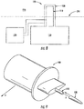
- an ice detector (100) comprises a probe surface (110).
- the probe surface (110) is an ultrasonic vibrating probe surface, such as used in a magnetostrictive ice detector architecture.
- a pyroelectric material layer (120) is disposed on the probe surface (110).
- the ice detector (100) also comprises a controller (130).
- the controller (130) can include circuitry or hardware and/or software configured to receive, transmit, and/or process data corresponding to an icing event.
- the ice detector (100) is coupled to an aircraft surface (200) such that a portion of the probe surface (110) is disposed in an exterior environment (210) of the aircraft.
- the exterior environment (210) can be considered to be a potential icing environment.
- a power supply (220) of the aircraft can provide power and/or a charge to the probe surface (110) and/or the controller (130).
- a probe surface described herein forms part of a capacitor detector architecture, such as in a capacitance probe.
- a capacitance probe architecture can include spatially separated conductive electrodes encapsulated in a non-conductive substrate to form a probe, where the amount of ice accumulated on the probe surface changes the capacitance of the probe, which can be measured by a capacitance measuring circuit.
- the probe surface of an ice detector described herein is part of an optical detector architecture.
- the probe surface is formed from a material (such as a metal, semiconductor, glass, or polymer) on which ice can form and accumulate, and a modulated light source is directed toward the probe surface.
- the light source can direct light toward the probe surface, and the probe surface can then transmit the light to an optical detector.
- the amount of light transmitted to the optical detector can indicate the amount of ice present on the probe surface.
- the probe surface of an ice detector described herein is a temperature-controlled or heated surface that can form part of an ice detector architecture based on the melting time of accumulated ice.
- the detector can operate periodically by beating the probe surface to a constant temperature.
- a microprocessor can measure the probe surface's rate of temperature increase by comparing the time it takes the probe surface to pass through two or more reference temperatures. The amount of accumulated ice can then be determined based on the rate of temperature increase, where the temperature increases at a slower rate when more ice has accumulated.
- the probe surface of an ice detector described herein can have one or more electrical properties suitable for use with a pyroelectric material layer described herein.
- the probe surface is electrically conductive and/or thermally insulating.
- the probe surface exhibits an electrical conductivity of at least about 1.0 x 10 -3 siemens per meter (S/m) at 20°C or at least about 1.5 x 10 -3 S/m at 20°C.
- the probe surface of an ice detector described herein exhibits a thermal diffusivity of no greater than about 10 x 10 -3 cm 2 /sec or no greater than about 5 x 10 -3 cm 2 /sec.
- Ice detectors described herein also comprise a pyroelectric material layer disposed on at least a portion of a probe surface described herein.
- the pyroelectric material layer can be disposed on any portion of the probe surface not inconsistent with the objectives of the present disclosure. In some cases, for example, the pyroelectric material layer covers all or a majority of the surface area of the probe surface. In some implementations, the pyroelectric material layer covers all or a majority of the surface area of the probe surface that is exposed to atmospheric conditions, such as the atmospheric conditions experience by the exterior of an aircraft. Therefore, in some implementations, an ice detector described herein is operable to detect the nucleation or formation of ice on the pyroelectric material layer of the ice detector, including by means of an ice detector architecture described hereinabove.
- the pyroelectric material layer of an ice detector described herein is disposed on up to about 99 percent, up to about 95 percent, up to about 90 percent, up to about 80 percent, up to about 70 percent, up to about 60 percent, up to about 50 percent, up to about 40 percent, up to about 30 percent, up to about 20 percent, or up to about 10 percent of the surface area of the probe surface or of the portion of the probe surface that is exposed to external atmospheric conditions.
- the pyroelectric material layer of an ice detector described herein is disposed on about 10 percent to about 99 percent, about 20 percent to about 90 percent, about 30 percent to about 80 percent, about 40 percent to about 99 percent, about 50 percent to about 99 percent, about 60 percent to about 99 percent, about 70 percent to about 99 percent, about 70 percent to about 95 percent, about 80 percent to about 95 percent, about 80 percent to about 99 percent, or about 90 percent to about 99 percent of the surface area of the probe surface or of the portion of the probe surface that is exposed to external atmospheric conditions.
- the pyroelectric material layer of an ice detector described herein can have any structure not inconsistent with the objectives of the present disclosure.
- the pyroelectric material layer is a continuous or substantially continuous layer.
- a continuous or substantially continuous layer in some cases, can be a layer having no substantial breaks or discontinuities between portions or segments of the layer.
- a continuous or substantially continuous layer can be a layer formed by a single continuous portion of pyroelectric material.
- the pyroelectric material layer can be a tiled layer formed from one or more distinct tiles of pyroelectric material placed adjacent to one another to form the layer.
- the pyroelectric material layer of an ice detector described herein can be a crystalline layer or a substantially crystalline layer.
- a "crystalline" layer for reference purposes herein, comprises a layer that has a crystalline microstructure.
- a crystalline or substantially crystalline layer can be single-crystalline or polycrystalline.
- a "substantially crystalline” layer can have a crystallinity of at least about 60 percent, at least about 70 percent, at least about 80 percent, at least about 90 percent, or at least about 95 percent, based on the total mass of the pyroelectric material.
- the pyroelectric material layer of an ice detector described herein is a quasi-amorphous layer.
- a "quasi-amorphous" layer for reference purposes herein, comprises a layer that exhibits a pyroelectric effect and has a partially crystalline and partially amorphous microstructure.
- a pyroelectric material layer of an ice detector described herein can comprise or be formed from any pyroelectric material not inconsistent with the objectives of the present disclosure.
- a pyroelectric material layer is formed from an inorganic material such as a ceramic material, poled ceramic material, or semiconductor material.
- a pyroelectric material layer is formed from a gallium nitride, a cesium nitrate, a lithium tantalate, a strontium titanate, a barium titanate, a barium strontium titanate, a strontium zirconate, a barium zirconate, a barium strontium zirconate, a lead zirconate, a strontium niobate, a barium niobate, a barium strontium niobate, or a combination thereof.
- the pyroelectric material layer of an ice detector described herein is formed from LiTaO 3 , SrTiO 3 , BaTiO 3 , (Sr x Ba 1-x )TiO 3 , SrZrO 3 , BaZrO 3 , (Sr x Ba 1-x )ZrO 3 , PbZrO 3 , SrNb 2 O 6 , BaNb 2 O 6 , (Sr x Ba 1-x )Nb 2 O 6 , Pb(Sc 0.5 Ta 0.5 )O 3 , or a combination thereof, wherein 0 ⁇ x ⁇ 1.
- the pyroelectric material layer comprises or is formed from an organic material such as a polymeric material.
- the pyroelectric material layer comprises or is formed from a polyvinylidene fluoride (PVDF) or a polyvinylidene fluoride-trifluoroethylene (PVDF-PrTE).
- PVDF polyvinylidene fluoride
- PVDF-PrTE polyvinylidene fluoride-trifluoroethylene
- the pyroelectric material layer of an ice detector described herein comprises or is formed from a composite material, such as a composite material comprising an inorganic material described hereinabove dispersed within a polymeric material described hereinabove.
- the pyroelectric material layer of an ice detector described herein comprises or is formed from a composite material comprising a lithium tantalate, a strontium titanate, a barium titanate, a barium strontium titanate, a strontium zirconate, a barium zirconate, a barium strontium zirconate, a lead zirconate, a strontium niobate, a barium niobate, or a barium strontium niobate dispersed in a PVDF or PVDF-PrTE matrix.
- the pyroelectric material layer of an ice detector described herein can comprise or be formed from a material having any pyroelectric coefficient not inconsistent with the objectives of the present disclosure.
- the pyroelectric material layer is formed from a material having a large pyroelectric coefficient.
- Equation (1) the total pyroelectric constant p of Equation (1) is determined at constant electric field and constant elastic stress, as described, for example, in Sidney B. Lang, "Pyroelectricity: From Ancient Curiosity to Modern Imaging Tool," Physics Today, August 2005 . "Constant elastic stress,” for reference purposes herein, means that the pyroelectric material is not clamped during the measurement but is instead free to expand or contract thermally.
- the pyroelectric material used to form the pyroelectric material layer has a total pyroelectric constant of about -20 C/m 2 K to about -600 C/m 2 K, about -25 C/m 2 K to about -400 C/m 2 K, about -75 C/m 2 K to about - 600 C/m 2 K, about -75 C/m 2 K to about -300 C/m 2 K, about -100 C/m 2 K to about -600 C/m 2 K, about -100 C/m 2 K to about -400 C/m 2 K, or about -100 C/m 2 K to about -300 C/m 2 K.
- a surface of the pyroelectric material layer of an ice detector described herein can be electrically charged.
- the charge can be a positive charge or a negative charge.
- a surface of the pyroelectric material layer can exhibit a local freezing point of water that differs from the local freezing point of water exhibited by an uncharged surface of the pyroelectric material.
- a charged surface of the pyroelectric material layer can exhibit a local freezing point of water that differs from the local freezing point of water exhibited by the probe surface in the absence of the pyroelectric material layer.
- a charged surface of the pyroelectric material layer can exhibit a local freezing point of water that differs from the local freezing point of water exhibited by a surface of an aircraft associated with an ice detector described herein.
- aircraft surfaces can include one or more critical flight surfaces described herein, such as one or more airfoil surfaces.
- the local freezing point of water exhibited by a charged surface of the pyroelectric material layer of an ice detector described herein is higher than the local freezing point of water exhibited by a different surface described hereinabove, such as an uncharged pyroelectric material layer surface, a probe surface, and/or an aircraft surface.
- a "local" freezing point of water for reference purposes here, refers to the freezing point of water within about 10 ⁇ m, within about 5 ⁇ m, within about 1 ⁇ m, or within about 0.5 ⁇ m of a surface.
- the increase or decrease of a local freezing point of water of a pyroelectric material layer surface described herein can be selected based on the charge of the pyroelectric material layer.
- a positively charged surface of the pyroelectric material layer exhibits a local freezing point of water that is greater than the local freezing point of water exhibited by a different surface described herein, such as an aircraft surface.
- the difference between the local freezing point of water of a surface of the pyroelectric material layer and the local freezing point of water of a different surface can be up to about 15°C, up to about 10°C, up to about 8°C, up to about 5°C, up to about 2°C, up to about 1°C, or up to about 0.5°C, including when the water is supercooled liquid water.
- the difference between the local freezing point of water on a surface of the pyroelectric material layer and the local freezing point of water on a different surface described herein can be between about 0.1°C and about 15°C, between about 0.5°C and about 10°C, between about 0.5°C and about 8°C, between about 0.5°C and about 5°C, between about 1°C and about 15°C, between about 1°C and about 10°C, between about 1°C and about 8°C, between about 1°C and about 5°C, between about 3°C and about 15°C, between about 3°C and about 10°C, between about 5°C and about 15°C, or between about 5°C and about 10°C.
- the pyroelectric material layer of an ice detector described herein can have any thickness not inconsistent with the objectives of the present disclosure.
- the pyroelectric material layer has an average thickness of up to about 500 ⁇ m, up to about 100 ⁇ m, up to about 10 ⁇ m, up to about 1 ⁇ m, up to about 500 nm, or up to about 100 nm.
- the pyroelectric material layer has an average thickness of about 10 nm to about 500 ⁇ m, about 10 nm to about 500 nm, about 10 nm to about 100 nm, about 50 nm to about 500 ⁇ m, about 50 nm to about 500 nm, about 100 nm to about 100 ⁇ m, about 100 nm to about 10 ⁇ m, about 100 nm to about 1 ⁇ m, about 500 nm to about 500 ⁇ m, about 500 nm to about 100 ⁇ m, about 500 nm to about 10 ⁇ m, about 500 nm to about 1 ⁇ m, about 1 ⁇ m to about 500 ⁇ m, about 1 ⁇ m to about 100 ⁇ m, or about 1 ⁇ m to about 10 ⁇ m.
- Ice detectors described herein also comprise one or more additional layers disposed between the probe surface and the pyroelectric material layer of the ice detector. Any additional layers not inconsistent with the objectives of the present disclosure may be used.
- an additional layer provides a desired electrical and/or thermal property.
- one or more additional layers is electrically conductive and/or thermally insulating.
- one or more additional layers exhibits an electrical conductivity of at least about 1.0 x 10 -3 S/m at 20°C or at least about 1.5 x 10 -3 S/m at 20°C.
- one or more additional layers exhibits a thermal diffusivity of no greater than about 10 x 10 -3 cm 2 /sec or no greater than about 5 x 10 -3 cm 2 /sec.
- an additional layer disposed between the probe surface and the pyroelectric material layer of an ice detector described herein can also facilitate coupling or adhesion of the probe surface and the pyroelectric material layer to one another.
- an ice detector described herein further comprises an adhesive material layer disposed between the probe surface and the pyroelectric material layer. Any adhesive material not inconsistent with the objectives of the present disclosure may be used. In some cases, the adhesive material of an adhesive material layer described herein exhibits an electrical conductivity and/or a thermal diffusivity described hereinabove.
- the adhesive material of an adhesive material layer described herein exhibits an electrical conductivity of at least about 1.0 x 10 -3 S/m at 20°C or at least about 1.5 x 10 -3 S/m at 20°C and also exhibits a thermal diffusivity of no greater than about 10 x 10 -3 cm 2 /sec or no greater than about 5 x 10 -3 cm 2 /sec.
- an adhesive material of an adhesive material layer described herein can be a fluid material or a solid material.
- an adhesive material comprises an animal protein-based adhesive material such as a collagen glue, albumin glue, casein glue, or meat glue.
- An adhesive material can also comprise a plant-based adhesive material such as a resin or starch.
- An adhesive material can also comprise a synthetic adhesive material such as a synthetic monomer glue or a synthetic polymer glue.
- an adhesive material comprises an acrylonitrile, a cyanoacrylate, or an acrylic glue or a combination thereof.
- an adhesive material comprises an epoxy resin, an epoxy putty, an ethylene-vinyl acetate, a phenol formaldehyde resin, a polyamide, a polyester resin, a polyethylene hot-melt glue, a polypropylene glue, a polysulfide, a polyurethane, a polyvinyl acetate, a polyvinyl alcohol, a polyvinyl chloride, a polyvinylpyrrolidone, a rubber cement, a silicone, or a styrene acrylate copolymer, or a combination or mixture thereof.
- an adhesive material comprises Gorilla Glue or Loctite 3888.
- an additional layer such as an adhesive material layer can have an average thickness of up to about 1 mm, up to about 0.5 mm, or up to about 500 ⁇ m.
- an additional layer such as an adhesive material layer has an average thickness of about 500 nm to about 1 mm, about 1 ⁇ m to about 500 ⁇ m, or about 10 ⁇ m to about 500 ⁇ m.
- an ice detector described herein can be made or assembled in any manner not inconsistent with the objectives of the present disclosure.
- an ice detector can be made by modifying an existing ice detector such as an existing commercial ice detector, as described further herein below.
- An existing ice detector in some cases, can be modified by forming a pyroelectric material layer on a probe surface of the existing ice detector, the probe surface being operable to detect the formation or nucleation of ice on the probe surface, including in a manner described hereinabove.
- Non-limiting examples of commercial ice detectors suitable for use in some implementations described herein include Goodrich 0781LH1, Goodrich 0781ND, and Meggitt/Vibro-Meter EW-140 ice detectors.
- a pyroelectric material layer can be formed or disposed on an existing probe surface in any manner not inconsistent with the objectives of the present disclosure.
- a pyroelectric material layer is disposed on a probe surface by covering or "capping" at least a portion of the probe surface with a shaped "cap" of pyroelectrical material that is configured to at least partially cover the probe surface.
- an adhesive material can first be applied to the probe surface and/or the interior of the cap. The cap of pyroelectric material can then be applied to the probe surface.
- FIG. 9 Such a method of disposing a pyroelectric material layer on a probe surface is illustrated in FIG. 9 . As understood by one of ordinary skill in the art, the various elements depicted in FIG. 9 are representational and are not necessarily drawn to scale.
- an ice detector (100) comprises a probe surface (110).
- the probe surface (110) can be an ultrasonic vibrating probe surface, such as used in a magnetostrictive ice detector architecture described herein above.
- the ice detector (100) can be coupled to an aircraft (not shown) such that the ice detector (100) moves in direction (A) when the aircraft is in flight.
- a pyroelectric material layer can be disposed on the probe surface (110) by sliding or fitting a cap (120) formed from a pyroelectric material over or onto the probes surface (110), as indicated by the arrow (B) in FIG. 9 .
- the cap (120) can have any shape and dimensions not inconsistent with the objectives of the present disclosure.
- the cap (120) has a hollow cylindrical or conical shape.
- a hollow cap (120) can have a wall thickness of no greater than about 0.127 cm (0.05 inches).
- an adhesive material layer (not shown) can be disposed between the cap (120) and the probe surface (110) to facilitate secure coupling of the cap (120) and the probe surface (110) and/or to provide one or more desired electrical or thermal properties, as described further hereinabove.
- a pyroelectric material layer can also be disposed on an existing probe surface in other manners.
- a probe surface is dipped or otherwise contacted with a molten pyroelectric material, such as a molten pyroelectric polymer material or a molten pyroelectric ceramic material.
- a pyroelectric material can also be disposed on a probe surface using a vapor or plasma deposition technique, such as a vacuum deposition, plasma sputtering, physical vapor deposition, or chemical vapor deposition technique.
- a pyroelectric material layer is disposed on an existing probe surface in a tiled manner.
- tiles formed from the pyroelectric material are disposed on the probe surface using an adhesive material, including an adhesive material described hereinabove.
- the tiles can have any dimensions not inconsistent with the objectives of the present disclosure.
- the dimensions of the pyroelectric material tiles are selected based on the shape and/or surface area of the probe surface, the chemical composition of the probe surface, the type of ice detector, and/or the chemical composition or pyroelectric properties of the pyroelectric material.
- the manner of disposing a pyroelectric material layer described herein on a probe surface can be selected based on the mechanical properties of the pyroelectric material (such as its brittleness or ability to be machined into a desired shape), the physical properties of the pyroelectric material (such as its melting point), the chemical composition of the pyroelectric material, the chemical composition of the probe surface, the morphology of the probe surface, and/or the type of ice detector.
- modifying an existing ice detector in a manner described herein can improve one or more performance characteristics of the ice detector.
- improving the performance characteristics of an ice detector comprises reducing the false negatives of the ice detector and/or increasing the range of atmospheric conditions in which the ice detector can reliably operate.
- a method of detecting ice formation on an aircraft comprises disposing an ice detector described herein on an exterior surface of the aircraft and generating a charge on a surface of the pyroelectric material layer of the ice detector to alter the local freezing point of water on the surface of the pyroelectric material layer.
- generating a charge on the surface of the pyroelectric material layer increases the local freezing point of water on the surface.
- the surface can be an exterior surface of the pyroelectric material layer, including an exterior surface exposed to the external environment of the aircraft.
- a charge is generated on the surface of the pyroelectric material layer while the aircraft is in flight.
- a method described herein further comprises providing a signal in response to the formation of ice on the surface of the pyroelectric material layer of the ice detector.
- the local freezing point of water on the surface of the pyroelectric material layer is greater than the local freezing point of water on one or more flight surfaces of the aircraft.
- the local freezing point of water on the surface of the pyroelectric material layer is greater than the local freezing point of water on a wing leading edge, an empennage leading edge, or an engine inlet leading edge of the aircraft.
- a method described herein can be used to detect the presence of icing conditions prior to the formation of ice on one or more critical flight surfaces, including in real-time while the aircraft is in flight.
- methods of detecting ice formation on an aircraft comprise disposing an ice detector described herein on an exterior surface or skin of the aircraft.
- Any ice detector described hereinabove may be used.
- the ice detector is an accretion-type ice detector comprising a probe surface and a pyroelectric material layer disposed on at least a portion of the probe surface.
- the pyroelectric material layer of the ice detector is a continuous or substantially continuous layer. In other instances, the pyroelectric material layer is a tiled layer.
- the pyroelectric material layer of an ice detector described herein is formed from LiTaO 3 , SrTiO 3 , BaTiO 3 , (Sr x Ba 1-x )TiO 3 , SrZrO 3 , BaZrO 3 , (Sr x Ba 1-x )ZrO 3 , PbZrO 3 , SrNb 2 O 6 , BaNb 2 O 6 , (Sr x Ba 1-x )Nb 2 O 6 , Pb(Sc 0.5 Ta 0.5 )O 3 , or a combination thereof.
- an ice detector described herein can be disposed on the exterior surface or skin of the aircraft in any location and in any manner not inconsistent with the objectives of the present disclosure.
- the ice detector is disposed on the exterior surface of the forward fuselage section of the aircraft.
- other configurations are also possible.
- Methods described herein also comprise generating a charge on a surface of the pyroelectric material layer of the ice detector to alter the local freezing point of water on the surface of the pyroelectric material layer.
- a charge can be generated on the surface of the pyroelectric material layer in any manner not inconsistent with the objectives of the present disclosure. In some cases, the charge generated on the surface of the pyroelectric material layer is a positive charge. In other instances, the charge generated on the surface of the pyroelectric material layer is a negative charge.
- the sign of the generated charge in some implementations, can be selected as desired by a user based on which type of charge produces an increase in the local freezing point of water on the pyroelectrical material layer.
- a positively charged surface of the pyroelectric material layer exhibits a higher local freezing point of water, and a negatively charged surface of the pyroelectric material layer exhibits a lower local freezing point of water.
- generating a charge on the surface of the pyroelectric material layer can comprise generating a positive charge to increase the local freezing point of water on the surface.
- a pyroelectric material layer is either heated or cooled based on whether a positive or a negative charge is desired on the surface. For example, in some implementations, heating a pyroelectric material layer generates a positive charge on the surface of the layer, and cooling a pyroelectric material layer generates a negative charge on the surface of the layer. Further, heating or cooling a pyroelectric material layer can be carried out in any manner not inconsistent with the objectives of the present disclosure. In some cases, for example, heating is carried out using an electric heating element in thermal contact with the pyroelectric material layer.
- a method described herein also comprises providing a signal in response to the formation of ice on the surface of the pyroelectric material layer of an ice detector described herein.
- the signal can be provided in any manner not inconsistent with the objectives of the present disclosure.
- a signal is provided to the operator of the aircraft when a predetermined amount of icing has occurred on the ice detector, such as an amount of icing corresponding to a maximum amount of icing or less than a maximum amount of icing considered to be safe for flight.
- a signal is provided to the operator of the aircraft when any icing occurs on the ice detector.
- the signal can be a visual signal such as a flashing light or other display indicator, or an auditory signal such as a buzzing, beeping, chiming, or verbal signal. Other signals may also be used.
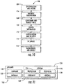
- exemplary method (100) may include specification and design (104) of the aircraft (102) and material procurement (106).
- component and subassembly manufacturing (108) and system integration (110) of the aircraft (102) takes place.
- the aircraft (102) may go through certification and delivery (112) in order to be placed in service (114).
- routine maintenance and service (116) which may also include modification, reconfiguration, retrofitting, and so on).
- a system integrator may include without limitation any number of aircraft manufacturers and major-system subcontractors; a third party may also include without limitation any number of venders, subcontractors, and suppliers; and an operator may be an airline, leasing company, military entity, service organization, and so on.
- the aircraft (102) produced by exemplary method (100) may include an airframe (118) with a plurality of systems (120) and an interior (122).
- high-level systems (120) include one or more of a propulsion system (124), an electrical system (126), a hydraulic system (128), and an environmental system (130). Any number of other systems may also be included.
- a propulsion system 124
- an electrical system 126
- a hydraulic system 126
- an environmental system 130
- Any number of other systems may also be included.
- an aerospace example is shown, the principles of the disclosure may be applied to other industries, such as the automotive industry.
- Apparatus and methods described herein may be employed during any one or more of the stages of the production and service method (100).
- one or more ice detectors described herein may be utilized during the component and subassembly manufacturing stage (108), including to substantially improve the performance of the aircraft (102).
- one or more ice detectors or methods described herein may be utilized while the aircraft (102) is in service (114).
- one or more ice detectors described herein may be used during the maintenance and service stage (116), including to repair and/or efficiently retrofit the aircraft (102) to improve the safety of the aircraft (102) without the need for substantial redesign or reconfiguration of the aircraft (102).
- An ice detector is assembled as follows. First, a commercial magnetostrictive ice detector is obtained.
- the ice detector can be a Goodrich 0781LH1, Goodrich 0781ND, or Meggitt/Vibro-Meter EW-140 ice detector.
- the ice detector includes an ultrasonic vibrating probe.
- a block of LiTaO 3 is machined into the shape of a hollow, substantially conical or cylindrical cap, as illustrated in FIG. 9 .
- the cap of LiTaO 3 has a maximum wall thickness of 0.127 cm (0.05 inches), a height of 2.67 cm (1.05 inches), and an outer diameter of 0.889 cm (0.35 inches).
- the LiTaO 3 cap Prior to use, the LiTaO 3 cap is cleaned by placing the cap in an ultra-sonic bath of toluene for 4 minutes. Following sonication in toluene, the cap is placed in an ultra-sonic bath of water for 4 minutes. Next, the cap is treated in a plasma asher for 30 minutes (34% Ar, 66% O 2 , 250 Watts, 0.5 mbar). Finally, the cap is placed in a desiccator for approximately 4 hours.
- a thin layer of adhesive is applied to the entire surface area of the probe of the magnetostrictive ice detector.
- the adhesive has a thermal diffusivity of less than about 5 x 10 -3 cm 2 /sec and an electrical conductivity of at least about 1.5 x 10 -3 S/m at 20°C.
- the LiTaO 3 cap is then carefully pressed onto the probe by a user wearing latex gloves or in some other manner that avoids human skin contact with the apparatus during assembly.
- the cap is pressed onto the probe in a manner to provide a flush fit of the cap with the strut surface or other supporting surface upon which the probe is mounted. Any excess adhesive pressed out of the open end of the cap is then removed by wiping.
Landscapes
- Physics & Mathematics (AREA)
- General Physics & Mathematics (AREA)
- Engineering & Computer Science (AREA)
- Aviation & Aerospace Engineering (AREA)
- Photometry And Measurement Of Optical Pulse Characteristics (AREA)
- Investigating Or Analyzing Materials Using Thermal Means (AREA)
- Geophysics And Detection Of Objects (AREA)
Claims (13)
- Verfahren zur Erkennung von Eisbildung an Flugzeugen, wobei das Verfahren umfasst:Anordnen eines Eisdetektors (100) an einer Außenfläche (200) des Flugzeugs, wobei der Eisdetektor eine Sondenoberfläche (110) und eine pyroelektrische Materialschicht (120), die wenigstens an einem Abschnitt der Sondenoberfläche (110) angeordnet ist, umfasst; undErzeugen einer Ladung an einer Oberfläche der pyroelektrischen Materialschicht (120), um den örtlichen Gefrierpunkt von Wasser an der Oberfläche der pyroelektrischen Materialschicht (120) zu erhöhen.
- Verfahren gemäß Anspruch 1, das weiterhin umfasst: Bereitstellen eines Signals als Reaktion auf die Bildung von Eis an der Oberfläche der pyroelektrischen Materialschicht (120).
- Verfahren gemäß den Ansprüchen 1 und 2, wobei der Eisdetektor (100) auf der Außenfläche (200) des vorderen Rumpfabschnitts des Flugzeugs angeordnet ist.
- Verfahren gemäß den Ansprüchen 1 bis 3, wobei es sich bei dem Eisdetektor (100) um einen Akkretions-Eisdetektor handelt.
- Verfahren gemäß den Ansprüchen 1 bis 4, wobei es sich bei der pyroelektrischen Materialschicht (120) um eine durchgehende oder im Wesentlichen durchgehende Schicht handelt.
- Verfahren gemäß den Ansprüchen 1 bis 5, wobei es sich bei der pyroelektrischen Materialschicht (120) um eine gekachelte Schicht handelt.
- Verfahren gemäß den Ansprüchen 1 bis 6, wobei die pyroelektrische Materialschicht (120) aus LiTaO3, SrTiO3, BaTiO3, (SrxBa1-x)TiO3, SrZrO3, BaZrO3, (SrxBa1-x)ZrO3, PbZrO3, SrNb2O6, BaNb2O6, (SrxBa1-x)Nb2O6, Pb(Sc0,5Ta0,5)O3, oder einer Kombination davon gebildet wird.
- Verfahren gemäß den Ansprüchen 1 bis 7, wobei der örtliche Gefrierpunkt von Wasser an der Oberfläche der pyroelektrischen Materialschicht (120) größer ist als der örtliche Gefrierpunkt von Wasser auf einer oder mehreren Flugzeug-Flugflächen (200).
- Verfahren gemäß Anspruch 8, wobei die eine oder die mehreren Flugzeug-Flugflächen eine Tragflächenvorderkante, eine Leitwerkvorderkante oder eine Triebwerkeinlassvorderkante umfassen.
- Verfahren gemäß den Ansprüchen 1 bis 8, wobei es sich bei der auf der pyroelektrischen Materialschicht (120) erzeugten Ladung um eine positive Ladung handelt.
- Eisdetektor (100), der umfasst:eine Sondenoberfläche (110); undeine pyroelektrische Materialschicht (120), die an wenigstens einem Abschnitt der Sondenoberfläche (110) angeordnet ist, wobei die Oberfläche der pyroelektrischen Materialschicht (120) dazu konfiguriert ist, wenn sie aufgeladen ist, einen örtlichen Gefrierpunkt von Wasser aufzuweisen, der größer ist als der örtliche Gefrierpunkt von Wasser, den die Sondenoberfläche (110) aufweist, wenn keine pyroelektrische Materialschicht (120) vorhanden ist, wobei die Sondenoberfläche (110) Teil einer magnetostriktiven Detektorarchitektur ist.
- Detektor gemäß Anspruch 11, wobei es sich bei der pyroelektrischen Materialschicht (120) um eine kristalline Schicht handelt.
- Detektor gemäß Anspruch 11, wobei es sich bei der pyroelektrischen Materialschicht (120) um eine quasi-amorphe Schicht handelt.
Applications Claiming Priority (1)
| Application Number | Priority Date | Filing Date | Title |
|---|---|---|---|
| US14/050,978 US9612163B2 (en) | 2013-10-10 | 2013-10-10 | Methods and apparatus for detecting ice formation on aircraft |
Publications (2)
| Publication Number | Publication Date |
|---|---|
| EP2860112A1 EP2860112A1 (de) | 2015-04-15 |
| EP2860112B1 true EP2860112B1 (de) | 2018-08-15 |
Family
ID=51390020
Family Applications (1)
| Application Number | Title | Priority Date | Filing Date |
|---|---|---|---|
| EP14181926.8A Active EP2860112B1 (de) | 2013-10-10 | 2014-08-22 | Verfahren und Vorrichtung zur Erkennung von Eisbildung an Flugzeugen |
Country Status (8)
| Country | Link |
|---|---|
| US (1) | US9612163B2 (de) |
| EP (1) | EP2860112B1 (de) |
| JP (2) | JP6487658B2 (de) |
| CN (1) | CN104802997B (de) |
| AU (1) | AU2014208229B2 (de) |
| BR (1) | BR102014021839B1 (de) |
| CA (1) | CA2857891C (de) |
| RU (1) | RU2662348C2 (de) |
Families Citing this family (22)
| Publication number | Priority date | Publication date | Assignee | Title |
|---|---|---|---|---|
| US9970824B2 (en) * | 2015-06-29 | 2018-05-15 | Pratt & Whitney Canada Corp. | Sensor probe with anti-icing |
| CN105869212B (zh) * | 2016-03-11 | 2018-10-12 | 空气动力学国家重点实验室 | 一种冰形简化方法 |
| CN105857621A (zh) * | 2016-05-06 | 2016-08-17 | 武汉航空仪表有限责任公司 | 一种一体化的结冰探测器 |
| US10450075B2 (en) | 2017-08-28 | 2019-10-22 | Rosemount Aerospace Inc. | Method of making a magnetostrictive oscillator ice rate sensor probe |
| US10696412B2 (en) * | 2017-09-29 | 2020-06-30 | The Boeing Company | Combined fluid ice protection and electronic cooling system |
| US11465759B2 (en) | 2018-07-13 | 2022-10-11 | The Boeing Company | Multi-mode generator for ice protection on aircraft |
| CN110127061A (zh) * | 2019-05-13 | 2019-08-16 | 成都凯天电子股份有限公司 | 提高结冰探测器探测杆敏感度的方法 |
| EP4062160B1 (de) * | 2019-11-22 | 2025-07-16 | KOC Universitesi | Vorrichtung und verfahren zur überwachung der eisbildung und enteisung |
| US12024300B2 (en) | 2019-12-02 | 2024-07-02 | Lockheed Martin Corporation | Method and system for ice detection |
| CN112046761B (zh) * | 2020-08-04 | 2021-10-15 | 中国空气动力研究与发展中心计算空气动力研究所 | 一种基于统计检验和滤波的飞机结冰在线探测方法 |
| CN112572809B (zh) * | 2020-12-17 | 2022-11-22 | 中国航空工业集团公司成都飞机设计研究所 | 一种适用于无人机平台的混合式结冰探测方法 |
| JP7644628B2 (ja) | 2021-03-19 | 2025-03-12 | 株式会社Subaru | 着氷検出装置 |
| RU2758565C9 (ru) * | 2021-03-29 | 2021-12-06 | Акционерное общество "Научно-исследовательский институт современных телекоммуникационных технологий" (АО "НИИ СТТ") | Оптоэлектронный сигнализатор обледенения планера беспилотного воздушного судна |
| FR3123426B1 (fr) * | 2021-05-25 | 2024-02-09 | Airbus Operations Sas | Dispositif de mesure de l’epaisseur d’une accretion de givre sur une surface et aeronef muni d’un tel dispositif |
| WO2022265587A1 (en) * | 2021-06-14 | 2022-12-22 | Koc Universitesi | An ice sensor |
| CN114419836A (zh) * | 2021-11-12 | 2022-04-29 | 深圳市同为数码科技股份有限公司 | 基于双光谱检测的报警联动方法、装置、设备及介质 |
| CN114487101B (zh) * | 2021-12-31 | 2023-06-16 | 中国民航大学 | 冰点检测及积冰预警装置及方法 |
| CN114858472B (zh) * | 2022-05-26 | 2023-05-05 | 北京航空航天大学杭州创新研究院 | 包覆碳烟颗粒异质成核冰晶在压气机静叶二次结冰试验装置及方法 |
| CN114705435B (zh) * | 2022-06-06 | 2022-09-20 | 中国飞机强度研究所 | 一种气候实验室用飞机发动机结冰和吞水试验装置及方法 |
| US12416485B2 (en) | 2022-06-17 | 2025-09-16 | Rosemont Aerospace Inc. | Additive material integrated heater deposited or embedded within an ice detector |
| US20240017840A1 (en) * | 2022-07-15 | 2024-01-18 | Rosemount Aerospace Inc. | Temperature-based suppression of spurious ice signals |
| US12174149B2 (en) | 2022-08-18 | 2024-12-24 | Rosemount Aerospace Inc. | Variable shape sensing element of a magnetostrictive oscillating ice detector sensor for improved ice collection efficiency using additive manufacturing |
Family Cites Families (22)
| Publication number | Priority date | Publication date | Assignee | Title |
|---|---|---|---|---|
| SU669638A1 (ru) * | 1976-12-30 | 1986-10-07 | Предприятие П/Я В-2323 | Противообледенительна система летательного аппарата |
| GB1582673A (en) | 1977-02-18 | 1981-01-14 | Gauting Gmbh Apparatebau | Ice detector |
| CH656015A5 (en) | 1984-02-27 | 1986-05-30 | Vibro Meter Ag | Method of detecting a risk of freezing, warning device for implementing the method and its use |
| US5206806A (en) * | 1989-01-10 | 1993-04-27 | Gerardi Joseph J | Smart skin ice detection and de-icing system |
| JPH02260320A (ja) * | 1989-03-31 | 1990-10-23 | Mitsubishi Mining & Cement Co Ltd | 焦電性複合セラミックス積層体 |
| US5313202A (en) * | 1991-01-04 | 1994-05-17 | Massachusetts Institute Of Technology | Method of and apparatus for detection of ice accretion |
| US5678145A (en) * | 1996-06-24 | 1997-10-14 | Xerox Corporation | Xerographic charging and transfer using the pyroelectric effect |
| RU2234781C2 (ru) * | 1998-12-01 | 2004-08-20 | Трастиз Оф Дартмут Колледж | Способ и устройство для удаления льда с поверхностей |
| US6402093B1 (en) * | 2000-07-13 | 2002-06-11 | Lockheed Martin Corporation | Method and apparatus for autonomous de-icing |
| US6320511B1 (en) | 2000-11-28 | 2001-11-20 | Rosemount Aerospace Inc. | Ice detector configuration for improved ice detection at near freezing conditions |
| US6759962B2 (en) * | 2001-04-25 | 2004-07-06 | Rosemount Aerospace Inc. | Inflight ice detector to distinguish supercooled large droplet (SLD) icing |
| US6576922B1 (en) * | 2001-12-21 | 2003-06-10 | Texas Instruments Incorporated | Ferroelectric capacitor plasma charging monitor |
| EP1396425A1 (de) * | 2003-03-10 | 2004-03-10 | Auxitrol SA | Eisdetektor für ein breites Spektrum von Vereisungsbedingungen |
| FR2858595B1 (fr) * | 2003-11-18 | 2005-10-14 | Auxitrol Sa | Ensemble de detection de givre destine a etre monte sur aeronef |
| US20050230553A1 (en) * | 2004-03-31 | 2005-10-20 | Rosemount Aerospace Inc. | Ice detector for improved ice detection at near freezing condition |
| JP2007024596A (ja) * | 2005-07-13 | 2007-02-01 | Terumo Corp | 電子体温計 |
| GB0823121D0 (en) * | 2008-12-18 | 2009-01-28 | Penny & Giles Controls Ltd | Ice detection system |
| JP2012514289A (ja) * | 2008-12-31 | 2012-06-21 | エアバス オペレーションズ ゲーエムベーハー | 少なくとも1つの電熱式の加熱層、及び同加熱層を有する構造コンポーネントを備える加熱システム、加熱方法、並びに加熱機構を有する半完成のコンポーネント又は完成品のコンポーネントの製造方法 |
| DE102012208653B4 (de) | 2011-05-27 | 2019-04-25 | Technische Universität Bergakademie Freiberg | Verfahren zur Herstellung einer Oberflächenbeschichtung mit eisabweisenden Eigenschaften, Oberflächenbeschichtung und deren Verwendung |
| US8907798B2 (en) * | 2012-01-05 | 2014-12-09 | The Boeing Company | Supercooled large drop icing condition detection system |
| JP6377315B2 (ja) * | 2012-03-08 | 2018-08-22 | ザ・ボーイング・カンパニーThe Boeing Company | 過冷却された大粒の滴の着氷状態検出システム |
| US9359081B2 (en) * | 2012-06-12 | 2016-06-07 | The Boeing Company | Icing condition detection system |
-
2013
- 2013-10-10 US US14/050,978 patent/US9612163B2/en active Active
-
2014
- 2014-07-28 CA CA2857891A patent/CA2857891C/en active Active
- 2014-07-30 RU RU2014131607A patent/RU2662348C2/ru active
- 2014-07-30 AU AU2014208229A patent/AU2014208229B2/en active Active
- 2014-08-22 EP EP14181926.8A patent/EP2860112B1/de active Active
- 2014-09-03 BR BR102014021839-4A patent/BR102014021839B1/pt active IP Right Grant
- 2014-09-26 JP JP2014196229A patent/JP6487658B2/ja active Active
- 2014-10-09 CN CN201410528582.0A patent/CN104802997B/zh active Active
-
2018
- 2018-12-19 JP JP2018236948A patent/JP6757786B2/ja active Active
Non-Patent Citations (1)
| Title |
|---|
| None * |
Also Published As
| Publication number | Publication date |
|---|---|
| JP6757786B2 (ja) | 2020-09-23 |
| JP6487658B2 (ja) | 2019-03-20 |
| US9612163B2 (en) | 2017-04-04 |
| BR102014021839A2 (pt) | 2016-08-09 |
| JP2019059473A (ja) | 2019-04-18 |
| US20150103867A1 (en) | 2015-04-16 |
| EP2860112A1 (de) | 2015-04-15 |
| JP2015091688A (ja) | 2015-05-14 |
| RU2014131607A (ru) | 2016-02-20 |
| CA2857891C (en) | 2017-09-05 |
| AU2014208229B2 (en) | 2017-06-29 |
| CA2857891A1 (en) | 2015-04-10 |
| AU2014208229A1 (en) | 2015-04-30 |
| RU2662348C2 (ru) | 2018-07-25 |
| BR102014021839B1 (pt) | 2021-12-21 |
| CN104802997A (zh) | 2015-07-29 |
| CN104802997B (zh) | 2017-12-05 |
Similar Documents
| Publication | Publication Date | Title |
|---|---|---|
| EP2860112B1 (de) | Verfahren und Vorrichtung zur Erkennung von Eisbildung an Flugzeugen | |
| US10124901B2 (en) | Icing condition detection method | |
| EP2800690B1 (de) | Supergekühltes grosstropfen-vereisungsbedingungsdetektionssystem | |
| EP3228543B1 (de) | Eiserkennungssystem und -verfahren | |
| US5191791A (en) | Piezoelectric sensor | |
| EP2774851B1 (de) | Automatisierte Wassertropfenmessung und Eiserkennungssystem | |
| EP2636599B1 (de) | Supergekühltes Großtropfen-Eis-Erkennungssystem | |
| CN110567357A (zh) | 动态应变压电陶瓷探测结冰传感器 | |
| KR20190024696A (ko) | 자왜식 발진기 착빙 속도 센서 프로브를 만드는 방법 | |
| Brampton et al. | Actuation of bistable laminates by conductive polymer nanocomposites for use in thermal-mechanical aerosurface de-icing systems | |
| Johansen | Flight test results for autonomous icing protection solution for small unmanned aircraft | |
| Al-Masri | Experimental investigation on the icing physics and anti-/de-Icing technology of an aircraft pitot probe | |
| US20250389745A1 (en) | Piezoelectric deicing for probe faceplate | |
| CN207607654U (zh) | 一种可目视结冰探测装置和使用该装置的飞机 | |
| Hann et al. | Experimental Heat Loads for Electrothermal Anti-Icing and De-Icing on UAVs. Aerospace 2021, 8, 83 | |
| EP4685477A1 (de) | System und verfahren zur erkennung von eisablagerung | |
| Brampton et al. | Actuation of bistable laminates by conductive polymer nanocomposites for use in thermal-mechanical aerosurface de-icing |
Legal Events
| Date | Code | Title | Description |
|---|---|---|---|
| PUAI | Public reference made under article 153(3) epc to a published international application that has entered the european phase |
Free format text: ORIGINAL CODE: 0009012 |
|
| 17P | Request for examination filed |
Effective date: 20140822 |
|
| AK | Designated contracting states |
Kind code of ref document: A1 Designated state(s): AL AT BE BG CH CY CZ DE DK EE ES FI FR GB GR HR HU IE IS IT LI LT LU LV MC MK MT NL NO PL PT RO RS SE SI SK SM TR |
|
| AX | Request for extension of the european patent |
Extension state: BA ME |
|
| GRAP | Despatch of communication of intention to grant a patent |
Free format text: ORIGINAL CODE: EPIDOSNIGR1 |
|
| INTG | Intention to grant announced |
Effective date: 20180201 |
|
| GRAS | Grant fee paid |
Free format text: ORIGINAL CODE: EPIDOSNIGR3 |
|
| GRAP | Despatch of communication of intention to grant a patent |
Free format text: ORIGINAL CODE: EPIDOSNIGR1 |
|
| INTC | Intention to grant announced (deleted) | ||
| GRAA | (expected) grant |
Free format text: ORIGINAL CODE: 0009210 |
|
| GRAJ | Information related to disapproval of communication of intention to grant by the applicant or resumption of examination proceedings by the epo deleted |
Free format text: ORIGINAL CODE: EPIDOSDIGR1 |
|
| GRAL | Information related to payment of fee for publishing/printing deleted |
Free format text: ORIGINAL CODE: EPIDOSDIGR3 |
|
| INTG | Intention to grant announced |
Effective date: 20180702 |
|
| AK | Designated contracting states |
Kind code of ref document: B1 Designated state(s): AL AT BE BG CH CY CZ DE DK EE ES FI FR GB GR HR HU IE IS IT LI LT LU LV MC MK MT NL NO PL PT RO RS SE SI SK SM TR |
|
| REG | Reference to a national code |
Ref country code: CH Ref legal event code: EP Ref country code: GB Ref legal event code: FG4D Ref country code: AT Ref legal event code: REF Ref document number: 1029452 Country of ref document: AT Kind code of ref document: T Effective date: 20180815 |
|
| REG | Reference to a national code |
Ref country code: FR Ref legal event code: PLFP Year of fee payment: 5 |
|
| REG | Reference to a national code |
Ref country code: IE Ref legal event code: FG4D |
|
| REG | Reference to a national code |
Ref country code: DE Ref legal event code: R096 Ref document number: 602014030329 Country of ref document: DE |
|
| REG | Reference to a national code |
Ref country code: NL Ref legal event code: MP Effective date: 20180815 |
|
| REG | Reference to a national code |
Ref country code: LT Ref legal event code: MG4D |
|
| REG | Reference to a national code |
Ref country code: AT Ref legal event code: MK05 Ref document number: 1029452 Country of ref document: AT Kind code of ref document: T Effective date: 20180815 |
|
| PG25 | Lapsed in a contracting state [announced via postgrant information from national office to epo] |
Ref country code: NO Free format text: LAPSE BECAUSE OF FAILURE TO SUBMIT A TRANSLATION OF THE DESCRIPTION OR TO PAY THE FEE WITHIN THE PRESCRIBED TIME-LIMIT Effective date: 20181115 Ref country code: SE Free format text: LAPSE BECAUSE OF FAILURE TO SUBMIT A TRANSLATION OF THE DESCRIPTION OR TO PAY THE FEE WITHIN THE PRESCRIBED TIME-LIMIT Effective date: 20180815 Ref country code: BG Free format text: LAPSE BECAUSE OF FAILURE TO SUBMIT A TRANSLATION OF THE DESCRIPTION OR TO PAY THE FEE WITHIN THE PRESCRIBED TIME-LIMIT Effective date: 20181115 Ref country code: IS Free format text: LAPSE BECAUSE OF FAILURE TO SUBMIT A TRANSLATION OF THE DESCRIPTION OR TO PAY THE FEE WITHIN THE PRESCRIBED TIME-LIMIT Effective date: 20181215 Ref country code: AT Free format text: LAPSE BECAUSE OF FAILURE TO SUBMIT A TRANSLATION OF THE DESCRIPTION OR TO PAY THE FEE WITHIN THE PRESCRIBED TIME-LIMIT Effective date: 20180815 Ref country code: GR Free format text: LAPSE BECAUSE OF FAILURE TO SUBMIT A TRANSLATION OF THE DESCRIPTION OR TO PAY THE FEE WITHIN THE PRESCRIBED TIME-LIMIT Effective date: 20181116 Ref country code: RS Free format text: LAPSE BECAUSE OF FAILURE TO SUBMIT A TRANSLATION OF THE DESCRIPTION OR TO PAY THE FEE WITHIN THE PRESCRIBED TIME-LIMIT Effective date: 20180815 Ref country code: FI Free format text: LAPSE BECAUSE OF FAILURE TO SUBMIT A TRANSLATION OF THE DESCRIPTION OR TO PAY THE FEE WITHIN THE PRESCRIBED TIME-LIMIT Effective date: 20180815 Ref country code: LT Free format text: LAPSE BECAUSE OF FAILURE TO SUBMIT A TRANSLATION OF THE DESCRIPTION OR TO PAY THE FEE WITHIN THE PRESCRIBED TIME-LIMIT Effective date: 20180815 Ref country code: NL Free format text: LAPSE BECAUSE OF FAILURE TO SUBMIT A TRANSLATION OF THE DESCRIPTION OR TO PAY THE FEE WITHIN THE PRESCRIBED TIME-LIMIT Effective date: 20180815 |
|
| PG25 | Lapsed in a contracting state [announced via postgrant information from national office to epo] |
Ref country code: HR Free format text: LAPSE BECAUSE OF FAILURE TO SUBMIT A TRANSLATION OF THE DESCRIPTION OR TO PAY THE FEE WITHIN THE PRESCRIBED TIME-LIMIT Effective date: 20180815 Ref country code: LV Free format text: LAPSE BECAUSE OF FAILURE TO SUBMIT A TRANSLATION OF THE DESCRIPTION OR TO PAY THE FEE WITHIN THE PRESCRIBED TIME-LIMIT Effective date: 20180815 Ref country code: AL Free format text: LAPSE BECAUSE OF FAILURE TO SUBMIT A TRANSLATION OF THE DESCRIPTION OR TO PAY THE FEE WITHIN THE PRESCRIBED TIME-LIMIT Effective date: 20180815 |
|
| REG | Reference to a national code |
Ref country code: CH Ref legal event code: PL |
|
| PG25 | Lapsed in a contracting state [announced via postgrant information from national office to epo] |
Ref country code: LU Free format text: LAPSE BECAUSE OF NON-PAYMENT OF DUE FEES Effective date: 20180822 Ref country code: RO Free format text: LAPSE BECAUSE OF FAILURE TO SUBMIT A TRANSLATION OF THE DESCRIPTION OR TO PAY THE FEE WITHIN THE PRESCRIBED TIME-LIMIT Effective date: 20180815 Ref country code: PL Free format text: LAPSE BECAUSE OF FAILURE TO SUBMIT A TRANSLATION OF THE DESCRIPTION OR TO PAY THE FEE WITHIN THE PRESCRIBED TIME-LIMIT Effective date: 20180815 Ref country code: LI Free format text: LAPSE BECAUSE OF NON-PAYMENT OF DUE FEES Effective date: 20180831 Ref country code: ES Free format text: LAPSE BECAUSE OF FAILURE TO SUBMIT A TRANSLATION OF THE DESCRIPTION OR TO PAY THE FEE WITHIN THE PRESCRIBED TIME-LIMIT Effective date: 20180815 Ref country code: CH Free format text: LAPSE BECAUSE OF NON-PAYMENT OF DUE FEES Effective date: 20180831 Ref country code: CZ Free format text: LAPSE BECAUSE OF FAILURE TO SUBMIT A TRANSLATION OF THE DESCRIPTION OR TO PAY THE FEE WITHIN THE PRESCRIBED TIME-LIMIT Effective date: 20180815 Ref country code: EE Free format text: LAPSE BECAUSE OF FAILURE TO SUBMIT A TRANSLATION OF THE DESCRIPTION OR TO PAY THE FEE WITHIN THE PRESCRIBED TIME-LIMIT Effective date: 20180815 Ref country code: IT Free format text: LAPSE BECAUSE OF FAILURE TO SUBMIT A TRANSLATION OF THE DESCRIPTION OR TO PAY THE FEE WITHIN THE PRESCRIBED TIME-LIMIT Effective date: 20180815 |
|
| REG | Reference to a national code |
Ref country code: BE Ref legal event code: MM Effective date: 20180831 |
|
| REG | Reference to a national code |
Ref country code: DE Ref legal event code: R097 Ref document number: 602014030329 Country of ref document: DE |
|
| PG25 | Lapsed in a contracting state [announced via postgrant information from national office to epo] |
Ref country code: SK Free format text: LAPSE BECAUSE OF FAILURE TO SUBMIT A TRANSLATION OF THE DESCRIPTION OR TO PAY THE FEE WITHIN THE PRESCRIBED TIME-LIMIT Effective date: 20180815 Ref country code: SM Free format text: LAPSE BECAUSE OF FAILURE TO SUBMIT A TRANSLATION OF THE DESCRIPTION OR TO PAY THE FEE WITHIN THE PRESCRIBED TIME-LIMIT Effective date: 20180815 Ref country code: DK Free format text: LAPSE BECAUSE OF FAILURE TO SUBMIT A TRANSLATION OF THE DESCRIPTION OR TO PAY THE FEE WITHIN THE PRESCRIBED TIME-LIMIT Effective date: 20180815 |
|
| PLBE | No opposition filed within time limit |
Free format text: ORIGINAL CODE: 0009261 |
|
| STAA | Information on the status of an ep patent application or granted ep patent |
Free format text: STATUS: NO OPPOSITION FILED WITHIN TIME LIMIT |
|
| PG25 | Lapsed in a contracting state [announced via postgrant information from national office to epo] |
Ref country code: MC Free format text: LAPSE BECAUSE OF FAILURE TO SUBMIT A TRANSLATION OF THE DESCRIPTION OR TO PAY THE FEE WITHIN THE PRESCRIBED TIME-LIMIT Effective date: 20180815 |
|
| 26N | No opposition filed |
Effective date: 20190516 |
|
| PG25 | Lapsed in a contracting state [announced via postgrant information from national office to epo] |
Ref country code: BE Free format text: LAPSE BECAUSE OF NON-PAYMENT OF DUE FEES Effective date: 20180831 Ref country code: SI Free format text: LAPSE BECAUSE OF FAILURE TO SUBMIT A TRANSLATION OF THE DESCRIPTION OR TO PAY THE FEE WITHIN THE PRESCRIBED TIME-LIMIT Effective date: 20180815 |
|
| PG25 | Lapsed in a contracting state [announced via postgrant information from national office to epo] |
Ref country code: MT Free format text: LAPSE BECAUSE OF NON-PAYMENT OF DUE FEES Effective date: 20180822 |
|
| PG25 | Lapsed in a contracting state [announced via postgrant information from national office to epo] |
Ref country code: TR Free format text: LAPSE BECAUSE OF FAILURE TO SUBMIT A TRANSLATION OF THE DESCRIPTION OR TO PAY THE FEE WITHIN THE PRESCRIBED TIME-LIMIT Effective date: 20180815 |
|
| PG25 | Lapsed in a contracting state [announced via postgrant information from national office to epo] |
Ref country code: PT Free format text: LAPSE BECAUSE OF FAILURE TO SUBMIT A TRANSLATION OF THE DESCRIPTION OR TO PAY THE FEE WITHIN THE PRESCRIBED TIME-LIMIT Effective date: 20180815 Ref country code: HU Free format text: LAPSE BECAUSE OF FAILURE TO SUBMIT A TRANSLATION OF THE DESCRIPTION OR TO PAY THE FEE WITHIN THE PRESCRIBED TIME-LIMIT; INVALID AB INITIO Effective date: 20140822 |
|
| PG25 | Lapsed in a contracting state [announced via postgrant information from national office to epo] |
Ref country code: CY Free format text: LAPSE BECAUSE OF FAILURE TO SUBMIT A TRANSLATION OF THE DESCRIPTION OR TO PAY THE FEE WITHIN THE PRESCRIBED TIME-LIMIT Effective date: 20180815 Ref country code: MK Free format text: LAPSE BECAUSE OF NON-PAYMENT OF DUE FEES Effective date: 20180815 Ref country code: IE Free format text: LAPSE BECAUSE OF NON-PAYMENT OF DUE FEES Effective date: 20180822 |
|
| P01 | Opt-out of the competence of the unified patent court (upc) registered |
Effective date: 20230516 |
|
| PGFP | Annual fee paid to national office [announced via postgrant information from national office to epo] |
Ref country code: DE Payment date: 20250827 Year of fee payment: 12 |
|
| PGFP | Annual fee paid to national office [announced via postgrant information from national office to epo] |
Ref country code: GB Payment date: 20250827 Year of fee payment: 12 |
|
| PGFP | Annual fee paid to national office [announced via postgrant information from national office to epo] |
Ref country code: FR Payment date: 20250825 Year of fee payment: 12 |