EP2860096A1 - Vorrichtung und Verfahren zur Motorsteuerung eines elektrisch angetriebenen Fahrrads - Google Patents
Vorrichtung und Verfahren zur Motorsteuerung eines elektrisch angetriebenen Fahrrads Download PDFInfo
- Publication number
- EP2860096A1 EP2860096A1 EP20140167830 EP14167830A EP2860096A1 EP 2860096 A1 EP2860096 A1 EP 2860096A1 EP 20140167830 EP20140167830 EP 20140167830 EP 14167830 A EP14167830 A EP 14167830A EP 2860096 A1 EP2860096 A1 EP 2860096A1
- Authority
- EP
- European Patent Office
- Prior art keywords
- pedal
- pedal torque
- control unit
- estimated
- torque
- Prior art date
- Legal status (The legal status is an assumption and is not a legal conclusion. Google has not performed a legal analysis and makes no representation as to the accuracy of the status listed.)
- Withdrawn
Links
Images


Classifications
-
- B—PERFORMING OPERATIONS; TRANSPORTING
- B62—LAND VEHICLES FOR TRAVELLING OTHERWISE THAN ON RAILS
- B62M—RIDER PROPULSION OF WHEELED VEHICLES OR SLEDGES; POWERED PROPULSION OF SLEDGES OR SINGLE-TRACK CYCLES; TRANSMISSIONS SPECIALLY ADAPTED FOR SUCH VEHICLES
- B62M6/00—Rider propulsion of wheeled vehicles with additional source of power, e.g. combustion engine or electric motor
- B62M6/40—Rider propelled cycles with auxiliary electric motor
- B62M6/55—Rider propelled cycles with auxiliary electric motor power-driven at crank shafts parts
-
- B—PERFORMING OPERATIONS; TRANSPORTING
- B62—LAND VEHICLES FOR TRAVELLING OTHERWISE THAN ON RAILS
- B62M—RIDER PROPULSION OF WHEELED VEHICLES OR SLEDGES; POWERED PROPULSION OF SLEDGES OR SINGLE-TRACK CYCLES; TRANSMISSIONS SPECIALLY ADAPTED FOR SUCH VEHICLES
- B62M23/00—Transmissions characterised by use of other elements; Other transmissions
- B62M23/02—Transmissions characterised by use of other elements; Other transmissions characterised by the use of two or more dissimilar sources of power, e.g. transmissions for hybrid motorcycles
-
- B—PERFORMING OPERATIONS; TRANSPORTING
- B62—LAND VEHICLES FOR TRAVELLING OTHERWISE THAN ON RAILS
- B62M—RIDER PROPULSION OF WHEELED VEHICLES OR SLEDGES; POWERED PROPULSION OF SLEDGES OR SINGLE-TRACK CYCLES; TRANSMISSIONS SPECIALLY ADAPTED FOR SUCH VEHICLES
- B62M6/00—Rider propulsion of wheeled vehicles with additional source of power, e.g. combustion engine or electric motor
- B62M6/40—Rider propelled cycles with auxiliary electric motor
- B62M6/45—Control or actuating devices therefor
- B62M6/50—Control or actuating devices therefor characterised by detectors or sensors, or arrangement thereof
Definitions
- the present invention relates to an apparatus and a method for controlling a motor of an electrical powered cycle.
- a bike is configured of a front wheel which is a steering wheel and a rear wheel which is a driving wheel which are disposed at a front and a rear of a frame in a straight line and is configured to go forward by allowing a passenger to press a pedal connected to a rear wheel so as to rotate the rear wheel.
- the bike includes a power transmission apparatus, such as a chain and a bevel gear which transmit power generated from the pedal to the rear wheel.
- the power transmission apparatus of the chain type is configured to include a driving sprocket which is mounted at one side of the pedal, a driven sprocket which has a diameter smaller than that of the driving sprocket and is mounted at the rear wheel which is the driving wheel, and a chain which connects the driving sprocket to the driven sprocket.
- the driving sprocket integrally mounted with the pedal rotates and at the same time the rear wheel connected to the driven sprocket also rotates by the chain, such that the bike goes forward.
- the bike Since the bike is driven by a pedal effort generated when the user is pedaling, the bike does not have much difficulty in traveling at a flat road, but when the bike drives up a slope, such as a hill, much effort is required.
- an electrical powered cycle mounted with a motor so as to be driven using a driving force of the motor in addition to the pedal effort of the user has been developed recently.
- the electrical powered cycle uses the motor driven with a battery and is configured to be driven with only the pedal effort of the user, only the force of the motor driven with the battery, or both of the pedal effort and the force of the motor.
- the electric bike uses a torque sensor mounted at a shaft of the pedal to automatically control the driving force of the motor depending on a signal output from the torque sensor.
- a type of the torque sensor there are a magnetic type in which an inductor senses a magnetic field generated depending on the amount of twisting of a twist sensor coil to generate a voltage and a strain gauge type in which a twist sensor mounted between a pedal and a crank measures the magnetic field.
- the torque sensor is very expensive.
- the torque essentially senses the twisting of the shaft. In this case, the twisted amount is very insignificant and therefore needs to be precisely amplified.
- the present invention has been made in an effort to provide an apparatus and a method for controlling a motor of an electrical powered cycle capable of controlling the motor by detecting an acceleration of a pedal and calculating a pedal torque from the detected acceleration of the pedal.
- an apparatus for controlling a motor of an electrical powered cycle including: an acceleration sensor mounted in the electrical powered cycle to measure and output an acceleration; and a control unit extracting a pedal frequency synchronization sinusoidal component from the acceleration output from the acceleration sensor to estimate a pedal torque and then drive the motor depending on the estimated pedal torque.
- the control unit may detect gsin ⁇ + a as the pedal frequency synchronization sinusoidal component when a tilt angle of the cycle is set to be ⁇ , a gravitational acceleration among accelerations output from the acceleration sensor is set to be g, and an acceleration of a progress direction is set to be a.
- the control unit may drive the motor depending on an average estimated pedal torque which is an average value of the estimated pedal torque.
- the control unit may remove an offset from an average pedal torque and use the average pedal torque from which the offset is removed to drive the motor.
- the control unit may remove an offset from the estimated pedal torque and use the estimated pedal torque from which the offset is removed to drive the motor.
- the control unit may include: a pedal frequency component detector which detects gsin ⁇ + a as a pedal frequency synchronization sinusoidal component when a tilt angle of the cycle is set to be ⁇ , a gravitational acceleration among the accelerations output from the acceleration sensor is set to be g, and an acceleration of a progress direction is set to be a; a pedal torque calculator which estimates the pedal torque from the pedal frequency synchronization sinusoidal component from the pedal frequency component detector; and a controller which drives the motor depending on the estimated pedal torque calculated by the pedal torque calculator.
- the control unit may further include: an average pedal torque calculator which obtains an average estimated pedal torque from a difference between a maximum value and a minimum value for one pedal period of the estimated pedal torque calculated by the pedal torque calculator, and the controller may drive the motor depending on the average estimated pedal torque which is calculated by the average pedal torque calculator.
- the control unit may further include: an offset remover which removes the offset from the estimated pedal torque calculated by the pedal torque calculator, and the controller drives the motor depending on the estimated pedal torque from which the offset is removed.
- the control unit may include: a speed sensor measuring and outputting a speed of the cycle; a pedal angle sensor measuring and outputting a pedal angle; and a database storing an offset table in which offsets are tabulated by the speed of the cycle, a slope, and a maximum value and a minimum value of the pedal torque, and the offset controller may calculate the slope using the acceleration measured by the acceleration sensor, receive the speed of the cycle from the speed sensor, and receive the pedal angle from the pedal angle sensor to calculate the maximum value and the minimum value of the pedal torque calculated by the pedal torque calculator and then refer to the offsets of the offset table stored in a database depending on the slope, the speed of the cycle, and the maximum value and the minimum value to remove the offset of the estimated pedal torque.
- the apparatus for controlling a motor of an electrical powered cycle may further include: a display unit displaying a mode selection menu; and a selector switch receiving a selection signal of a passenger, wherein the control unit displays the mode selection menu on the display unit and when the passenger selects a mode using the selector switch, drives the motor depending on the estimated pedal torque depending on the selected mode.
- a method for controlling a motor of an electrical powered cycle including: (A) measuring and outputting, by an acceleration sensor, an acceleration of the electrical powered cycle; and (B) extracting, by a control unit, a pedal frequency synchronization sinusoidal component from the acceleration output from the acceleration sensor to estimate a pedal torque and then drive the motor depending on the estimated pedal torque.
- the method for controlling a motor of an electrical powered cycle may further include: (C) calculating, by the control unit, an average estimated pedal torque which is an average value of the estimated pedal torque, wherein the control unit drives the motor depending on the average estimated pedal torque.
- the method for controlling a motor of an electrical powered cycle may further include: after the estimating of the average estimated pedal torque in the step (C), (D) removing, by the control unit, an offset from the average estimated pedal torque and using the average estimated pedal torque from which the offset is removed to drive the motor.
- the method for controlling a motor of an electrical powered cycle may further include: after the estimating of the pedal torque in the step (B), (E) removing, by the control unit, the offset from the estimated pedal torque and using the estimated pedal torque from which the offset is removed to drive the motor.
- the step (E) may include: (E-1) receiving, by the control unit, a speed of the cycle measured by a speed sensor; (E-2) receiving, by the control unit, a pedal angle measured and output by a pedal angle sensor; (E-3) receiving, by the control unit, the pedal angle from the pedal angle sensor to calculate a maximum value and a minimum value of a pedal torque; (E-4) calculating, by the control unit, a slope from the acceleration measured by the acceleration sensor; and (E-5) referring to, by the control unit, offsets of an offset table stored in a database depending on a slope, a speed of the cycle, and a maximum value and a minimum value to remove the offset ofthe estimated pedal torque.
- the step (B) may include: (B-1) detecting, by the control unit, gsin ⁇ + a as a pedal frequency synchronization sinusoidal component when a tilt angle of the cycle is set to be ⁇ , a gravitational acceleration among the accelerations output from the acceleration sensor is set to be g, and an acceleration of a progress direction is set to be a; (B-2) estimating, by the control unit, the pedal torque from the pedal frequency synchronization sinusoidal component; and (B-3) driving, by the control unit, the motor depending on the calculated estimated pedal torque.
- the method for controlling a motor of an electrical powered cycle may further include: (F) displaying, by the control unit, a mode selection menu on a display unit; and (G) driving, by the control unit, the motor depending on the mode selected by the passenger using a selector switch.
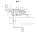
- FIGS. 1 to 4 are exemplified diagrams of an electrical powered cycle in which a motor control apparatus according to a preferred embodiment ofthe present invention is used.
- an electrical powered cycle in which a motor control apparatus according to an exemplary embodiment of the present invention is used includes a frame 1 having a truss structure or a general pipe structure, a front wheel 3 and a rear wheel 5 which are rotatably mounted on the frame 1, a handle 7 which is mounted at a front end ofthe frame 1, and a saddle 8 which is mounted at a central portion ofthe frame 1.
- the electrical powered cycle includes a crank shaft 14 which is rotatably mounted at a lower portion of a center of the frame 1, cranks 40 which face each other and radially extend from both ends of the crank shaft 14, and pedals 42 which are rotatably mounted at tips ofthe cranks 40.
- the electrical powered cycle includes driving units 20, 21, 22, 23, and 50 which are mounted at one portion of the frame 1 to generate a driving force and power transmission units 24, 25, 27, 28, 38, and 45 which are connected to the crank shalt 14 to transmit a pedal effort generated by rolling the pedals 42 and power from the driving units 20, 21, 22, 23, and 50 to the rear wheel 5.
- the driving units 20, 21, 22, 23, and 50 include a motor 20, a motor rotating shaft 21, a motor one-way clutch 22 which is mounted at the motor rotating shaft 21, a motor driving gear 23 which is mounted at the motor one-way clutch 22, and a battery 50 which is mounted between the handle 7 and the saddle 8 ofthe frame 1.
- the power transmission units 24, 25, 27, 28, 38, and 45 include a crank driven gear 24, a fastening part 25 which fixes the crank driven gear 24 to a driving sprocket, a driving sprocket 27, a driven sprocket 28, a crank one-direction clutch 38, and a chain 45 which connects the driving sprocket to the driven sprocket.
- the electrical powered cycle includes a fixture 10 which is formed at one side end of a crank housing 12.
- the fixture 10 which is a bolt is fixed to an outer wheel of the crank housing 12 by a tightening nut 10-4.
- a hole 10-2 of the fixture and a hole 10-3 ofthe fixture may be always maintained at a predetermined distance.
- the electrical powered cycle is provided with the motor control apparatus which includes an acceleration sensor 60 which is mounted in the crank housing 12, a control unit 62 which is mounted between the handle 7 and the saddle 8 ofthe frame 1, a display unit 64 which is mounted on the handle 7, a selector switch 66 which transmits a selection signal of a passenger, a speedometer 68 which is mounted at the rear wheel 5 to measure a speed of the cycle, a pedal angle sensor 70 which is mounted in the crank housing 12, and the like.
- the motor control apparatus which includes an acceleration sensor 60 which is mounted in the crank housing 12, a control unit 62 which is mounted between the handle 7 and the saddle 8 ofthe frame 1, a display unit 64 which is mounted on the handle 7, a selector switch 66 which transmits a selection signal of a passenger, a speedometer 68 which is mounted at the rear wheel 5 to measure a speed of the cycle, a pedal angle sensor 70 which is mounted in the crank housing 12, and the like.
- the electrical powered cycle to which the motor control apparatus according to the exemplary embodiment ofthe present invention is applied is operated as follows.
- crank shaft 14 rotates. Next, a rotational force ofthe crank shaft 14 is transmitted to the driving sprocket 27 through the crank 40.
- the driving sprocket 27 rotates to transmit the rotational force to the driven sprocket 28 through the chain 45 so as to rotate the rear wheel 5, such that the cycle goes forward.
- the acceleration sensor 60 measures and outputs acceleration of X, Y, and Z components including gravitational acceleration.
- control unit 62 extracts a pedal frequency synchronization sinusoidal component from the acceleration measured by the acceleration sensor 60 to estimate a pedal torque.
- control unit 62 extracts the pedal frequency synchronization sinusoidal component to estimate the pedal torque.
- control unit 62 controls the motor 20 to generate a driving force which is proportional to or follows the pedal torque estimated from the pedal frequency synchronization sinusoidal component.
- control unit 62 calculates an average estimated pedal torque which is an average value of the estimated pedal torque to be able to control the motor 20 so as to generate the driving force which is proportional to or follows the calculated average estimated pedal torque.
- control unit 62 removes an offset from the estimated pedal torque or the average estimated pedal torque and then uses the estimated pedal torque or the estimated average pedal torque from which the offset is removed to be able to control the motor 20 so as to generate the driving force which is proportional to or follows the pedal torque.
- the offset removal of the control unit 62 is made by using an offset which is calculated by receiving the speed of the cycle from the speed sensor 68, receiving a slope from the acceleration sensor 60, and using a maximum value and a minimum value of the estimated pedal torque.
- control unit 62 may calculate the offset based on Equations, but may easily calculate an offset using an offset table in which the offsets are tabulated by the speed of the cycle, the slope and the maximum value and the minimum value of the pedal torque.
- the driving force continuously transmitted to the driven gear 24 is transmitted to the driving sprocket 27 and is then transmitted to the driven sprocket 28 through the chain 45 to rotate the rear wheel 5.
- the control unit 62 controls the motor 20 so as to increase the driving force no more, such that the cycle may maintain a predetermined speed.
- control unit 62 may figure out the slope ofthe cycle from the acceleration of the cycle measured by the acceleration sensor 60 and when the slope of the cycle is equal to or more than a predetermined angle counterclockwise from a ground, makes the driving force of the motor 20 be a multiple of the estimated pedal torque in proportion to the slope, such that when the cycle drives up an inclined place, pedal effort dependency of the passenger may be reduced.
- the control unit 62 makes the driving force of the motor 20 be inversely proportional to the estimated pedal torque in proportion to the slope, such that when the cycle drives down an inclined place, the dependency ofthe motor may be reduced.
- control unit 62 provides various modes through a display unit 64 and when the passenger selects any one of the modes using the selector switch 66, drives the motor 20 depending on the selected mode.
- the mode which may be selected by the passenger there are an eco mode, a tour mode, a sport mode, a speed mode, and the like.
- the eco mode is a mode which allows the motor to provide the driving force corresponding to 30% of the estimated pedal torque
- the tour mode is a mode which allows the motor to provide the driving force corresponding to 50% ofthe estimated pedal torque
- the sport mode is a mode which allows the motor to provide the driving force corresponding to 55% of the estimated pedal torque
- the speed mode is a mode which allows the motor to provide the driving force corresponding to 60% ofthe estimated pedal torque.
- FIG. 5 is a configuration diagram of the motor control apparatus according to the preferred embodiment ofthe present invention.
- the motor control apparatus is configured to include the acceleration sensor 60, the control unit 62, the display unit 64, the selector switch 66, the speed sensor 68, and the pedal angle sensor 70.
- control unit 62 includes a pedal frequency component detector 210, a pedal torque calculator 220, an average pedal torque calculator 230, an offset remover 240, and a controller 250.
- the acceleration sensor 100 measures and outputs the acceleration of the cycle.
- the acceleration sensor 100 informs acceleration information of the X, Y, and Z components including the gravitational acceleration.
- control unit 62 extracts the pedal frequency synchronization sinusoidal component using the acceleration output from the acceleration sensor 60 and then estimates the pedal torque and controls the motor 20 using the estimated pedal torque from which the offset is removed.
- the pedal frequency component detector 210 of the control unit 62 extracts the pedal frequency synchronization sinusoidal component using the acceleration output from the acceleration sensor 60.
- the acceleration sensor 60 outputs the gravitational acceleration g, gsin ⁇ + a (a is an acceleration of a progress direction) which is the acceleration of the X component, and gcos ⁇ which is the acceleration ofthe Z component.
- the pedal frequency component detector 210 of the control unit 62 detects the gsin ⁇ + a, which is the acceleration ofthe X component output from the acceleration sensor 60, as the pedal frequency component.
- the pedal torque calculator 220 of the control unit 62 estimates the pedal torque by multiplying a mass m set by a manufacturer or a passenger of the cycle by the pedal frequency component detected by the pedal frequency component detector 210 to obtain the estimated pedal torque.
- the estimated pedal torque calculated by the pedal torque calculator 220 estimates the actual pedal torque well. The reason is as follows.
- an aerodynamic drag FDRAG is calculated based on the following Equation 1
- a friction force FFRIC is calculated based on the following Equation 2
- a slope fall force FGRAD1 is calculated based on the following Equation 3
- an acceleration force FGRAD2 is calculated based on the following Equation 4.
- FDRAG 1 2 ⁇ ⁇ ⁇ A f ⁇ C d ⁇ V 2
- the driving force generated the left pedal 42 has the sinusoidal component which varies depending on a rotating period of the pedal 42. This may be appreciated from FIG. 7 .
- an X axis represents an angle of the crank shaft and a Y axis represents the pedal torque.
- FIG. 7 repeatedly illustrates the state, such that the pedal torque has the sinusoidal component whic h varies depending on the rotating period.
- the pedal frequency component detector 210 detects the gsin ⁇ + a, which is the acceleration of the X component output from the acceleration sensor 60, as the pedal frequency component and the pedal torque calculator 220 of the control unit 62 obtains the estimated pedal torque by multiplying the mass m set by the manufacturer or the passenger of the cycle by the pedal frequency component detected by the pedal frequency component detector 210.
- the mass m set by the manufacturer or the passenger ofthe cycle is obtained by adding a mass m2 of the passenger to a mass m1 of the cycle.
- the mass m2 is set based on an average value of weights ofthe adult within a product sales area and when the passenger sets the mass m2, the mass m2 is set by setting the weight of the passenger.
- the pedal torque is a sum of AC component and offset component, in which the offset component maybe considered as, for example, Tbottom.
- the amount of the offset component Tbottom is relatively small and therefore has an insignificant effect on the performance. Therefore, a torque corresponding to a level which may be applied to the control of the motor without considering the offset component is detected.
- the average pedal torque calculator 230 obtains the average value using the estimated pedal torque calculated by the pedal torque calculator 220 to calculate the average pedal torque.
- an average pedal torque Tpedalaverage as the average value calculated by the average pedal torque calculator 230 is obtained from a difference between a maximum value m*atop and a minimum value m*abottom for one pedal period of the estimated pedal torque calculated by the pedal torque calculator 220 based on the following Equation 7.
- Tpedalaverage m * atop - abottom * 0.5
- the offset remover 240 outputs the estimated pedal torque which is calculated by the pedal torque calculator 220 and does not have an offset.
- a method of allowing the offset remover 240 to remove the offset from the estimated pedal torque calculated by the pedal torque calculator 220 is a method of subtracting a minimum value m*atop for a previous period from the estimated pedal torque for one period.
- a point at which the pedal angle becomes 180° may be set as the minimum value by using the pedal angle detected by the pedal angle sensor 70.
- the more precise offset removal may be performed with reference to a database 260 which stores the offset table depending on offset characteristics which represent the speed of the cycle, a Tpeak - Tbottom value for the previous period, and a typical value of inclination.
- the offset remover 240 receives the slope from the acceleration sensor 60, receives the speed ofthe cycle from the speed sensor 68, and receives the Tpeak and Tbottom of the estimated pedal torque from the pedal torque calculator 220 to read the corresponding offset value from the offset table and then subtracts and outputs the offset value from the estimated pedal torque or the average estimated pedal torque calculated by the pedal torque calculator 220 or the average pedal torque calculator 230.
- the database 260 stores the typical offset value depending on the slope and speed ofthe cycle and the difference between the Tpeak and Tbottom of the pedal torque.
- the display unit 64 provides a selection menu for various modes which are provided by the control unit 62 and displays the currently progressing mode, the speed or acceleration of the cycle, and the like.
- the selector switch 66 may allow the passenger to select any one mode from the mode menus which are displayed on the display unit 64.
- the mode which may be selected by the passenger there are the eco mode, the tour mode, the sport mode, the speed mode, and the like.
- the eco mode is a mode which allows the motor to provide the driving force corresponding to 30% of the estimated pedal torque
- the tour mode is a mode which allows the motor to provide the driving force corresponding to 50% ofthe estimated pedal torque
- the sport mode is a mode which allows the motor to provide the driving force corresponding to 55% of the estimated pedal torque
- the speed mode is a mode which allows the motor to provide the driving force corresponding to 60% ofthe estimated pedal torque.
- crank shaft 14 rotates.
- the rotational force of the crank shaft 14 is transmitted to the driving sprocket 27 through the crank 40.
- the driving sprocket 27 rotates to transmit the rotational force to the driven sprocket 28 through the chain 45 so as to rotate the rear wheel 5, such that the cycle goes forward.
- the acceleration sensor 60 measures and outputs the acceleration of X, Y, and Z components including the gravitational acceleration.
- the pedal frequency component detector 210 of the control unit 62 extracts the pedal frequency synchronization sinusoidal component from the acceleration measured by the acceleration sensor 60.
- the pedal torque calculator 220 of the control unit 62 extracts the pedal frequency synchronization sinusoidal component to estimate the pedal torque.
- the controller 250 ofthe control unit 62 controls the motor 20 to generate a driving force which is proportional to or follows the pedal torque estimated from the pedal frequency synchronization sinusoidal component.
- control unit 62 calculates the average estimated pedal torque which is the average value of the estimated pedal torque using the average pedal torque calculator 230 to be able to control the motor 20 so as to generate the driving force which is proportional to or follows the calculated average estimated pedal torque.
- control unit 62 removes the offset from the estimated pedal torque or the average estimated pedal torque using the offset remover 240 and then uses the estimated pedal torque or the average estimated pedal torque with the removed offset to be able to control the motor 20 so as to generate the driving force which is proportional to or follows the pedal torque.
- the offset remover 240 removes the offset by using an offset which is calculated by receiving the speed of the cycle from the speed sensor 68, receiving the slope from the acceleration sensor 60, and using the maximum value and the minimum value of the estimated pedal torque.
- the offset remover 240 may calculate the offset based on Equation, but may easily calculate the offset using the offset table in which the offsets are tabulated in the database 260 by the speed ofthe cycle, the slope, and the maximum value and the minimum value ofthe pedal torque.
- the controller 250 controls the motor 20 so as to increase the driving force no more, such that the cycle may maintain a predetermined speed.
- controller 250 may figure out the slope of the cycle from the acceleration of the cycle measured by the acceleration sensor 60 and when the slope of the cycle is equal to or more than a predetermined angle counterclockwise from a ground, makes the driving force of the motor 20 be a multiple of the estimated pedal torque in proportion to the slope, such that when the cycle drives up an inclined place, pedal effort dependency of the passenger may be reduced.
- the controller 250 makes the driving force of the motor 20 be inversely proportional to the estimated pedal torque in proportion to the slope, such that when the cycle drives down an inclined place, the dependency of the motor may be reduced.
- controller 250 provides various mode menus through the display unit 64 and when the passenger selects any one of the modes using the selector switch 66, drives the motor 20 depending on the selected mode.
- the acceleration sensor which is a very inexpensive element is mounted in the substrate.
- a unique variable among the parameters used in the preferred embodiments ofthe present invention is a total mass m (bicycle + passenger), when the total mass is an inputtable and typical value, it is possible to obtain the approximated torque required for the PAS control
- the torque sensor is removed, such that costs maybe significantly reduced.
- the space occupied by the torque sensor may be reduced and the sensor lines may be removed to reduce the possibility of failure.
- FIG. 8 is a flow chart of a method for controlling a motor of an electrical powered cycle according to a preferred embodiment ofthe present invention.
- the passenger first applies the pedal effort to the pedals 42 to rotate the crank shaft 14.
- the rotational force of the crank shaft 14 is transmitted to the driving sprocket 27 through the crank 40 to rotate the driving sprocket 27, such that the rotational force is transmitted to the driven sprocket 28 through the chain 45 to rotate the rear wheel 5, thereby going the cycle forward (S100).
- the acceleration sensor 60 measures and outputs the acceleration of X, Y, and Z components including the gravitational acceleration (S110).
- control unit extracts the pedal frequency synchronization sinusoidal component from the acceleration measured by the acceleration sensor (S120) to estimate the pedal torque (S130).
- control unit removes the offset from the estimated pedal torque (S140) and uses the estimated pedal torque from which the offset is removed to be able to control the motor to generate the driving force which is proportional to or follows the pedal torque (S 150).
- the offset removal of the control unit is made by using the offset which is calculated by receiving the speed ofthe cycle from the speed sensor, receiving the slope from the acceleration sensor, and using the maximum value and the minimum value of the estimated pedal torque.
- control unit may calculate the offset based on Equations, but may easily calculate the offset using the offset table in which the offsets are tabulated by the speed of the cycle, the slope, and the maximum value and the minimum value ofthe pedal torque.
- control unit calculates the average estimated pedal torque which is the average value of the estimated pedal torque to be able to control the motor so as to generate the driving force which is proportional to or follows the calculated average estimated pedal torque.
- control unit removes the offset from the average estimated pedal torque and uses the average estimated pedal torque from which the offset is removed to be able to control the motor to generate the driving force which is proportional to or follows the pedal torque.
- the control unit controls the motor so as to increase the driving force no more, such that the cycle may maintain a predetermined speed.
- control unit may figure out the slope ofthe cycle from the acceleration ofthe cycle measured by the acceleration sensor 60 and when the slope of the cycle is equal to or more than a predetermined angle counterclockwise from the ground, makes the driving force of the motor be a multiple of the estimated pedal torque in proportion to the slope, such that when the cycle drives up an inclined place, the pedal effort dependency of the passenger may be reduced.
- the control unit makes the driving force of the motor be inversely proportional to the estimated pedal torque in proportion to the slope, such that when the cycle drives down an inclined place, the dependency of the motor may be reduced.
- control unit provides various modes through the display unit and when the passenger selects any one of the modes using the selector switch, may drive the motor depending on the selected mode.
- the mode which may be selected by the passenger there are the eco mode, the tour mode, the sport mode, the speed mode, and the like.
- the torque sensor is removed, such that costs may be significantly reduced. Further, the space occupied by the torque sensor may be reduced and the sensor lines may be removed to reduce the possibility of failure.
- the acceleration sensor which is a very inexpensive element is mounted in the substrate.
- a unique variable among the parameters used in the preferred embodiments ofthe present invention is a total mass m (cycle + passenger), when the total mass is an inputtable and typical value, it is possible to obtain the approximated torque required for the PAS controLTherefore, according to the preferred embodiments of the present invention, the torque sensor is removed, such that costs may be significantly reduced.
- the space occupied by the torque sensor may be reduced and the sensor lines may be removed to reduce the possibility of failure.
Applications Claiming Priority (1)
| Application Number | Priority Date | Filing Date | Title |
|---|---|---|---|
| KR20130120762A KR20150042037A (ko) | 2013-10-10 | 2013-10-10 | 전동식 자전거의 모터제어 장치 및 그 방법 |
Publications (1)
| Publication Number | Publication Date |
|---|---|
| EP2860096A1 true EP2860096A1 (de) | 2015-04-15 |
Family
ID=50842029
Family Applications (1)
| Application Number | Title | Priority Date | Filing Date |
|---|---|---|---|
| EP20140167830 Withdrawn EP2860096A1 (de) | 2013-10-10 | 2014-05-12 | Vorrichtung und Verfahren zur Motorsteuerung eines elektrisch angetriebenen Fahrrads |
Country Status (2)
| Country | Link |
|---|---|
| EP (1) | EP2860096A1 (de) |
| KR (1) | KR20150042037A (de) |
Cited By (12)
| Publication number | Priority date | Publication date | Assignee | Title |
|---|---|---|---|---|
| US9637197B2 (en) * | 2015-07-01 | 2017-05-02 | GM Global Technology Operations LLC | Dynamic inertia compensation and pedal effort transformation for electric bike |
| FR3051432A1 (fr) * | 2016-05-17 | 2017-11-24 | Commissariat Energie Atomique | Procede et un systeme d'estimation d'un effort utile fourni par un individu pendant une activite physique consistant a executer un mouvement alternatif de pedalage sur un dispositif a pedalier |
| GB2557287A (en) * | 2016-12-05 | 2018-06-20 | Wen Sung Lee | Control device for an electric bicycle |
| EP3339156A1 (de) * | 2016-12-20 | 2018-06-27 | Beijing Xiaomi Mobile Software Co., Ltd. | Verfahren und vorrichtung zur steuerung eines fahrzeugs zur ausgabe von unterstützungsleistung |
| WO2019102495A1 (en) * | 2017-11-23 | 2019-05-31 | Ivroom Power Private Limited | Mid-drive unit for electric bicycle |
| EP3564110A4 (de) * | 2016-12-28 | 2020-01-01 | Yamaha Hatsudoki Kabushiki Kaisha | System mit elektrischer unterstützung und fahrzeug mit elektrischer unterstützung |
| WO2021162075A1 (ja) * | 2020-02-14 | 2021-08-19 | 本田技研工業株式会社 | 電動アシスト装置及び自転車 |
| WO2021162079A1 (ja) * | 2020-02-14 | 2021-08-19 | 本田技研工業株式会社 | 電動アシスト装置及び自転車 |
| JPWO2020158280A1 (ja) * | 2019-02-01 | 2021-09-30 | 本田技研工業株式会社 | 自転車用電動アシスト装置及び自転車 |
| DE102020206824A1 (de) | 2020-06-02 | 2021-12-02 | Robert Bosch Gesellschaft mit beschränkter Haftung | Verfahren und Vorrichtung zur Ansteuerung eines Antriebs eines Zweirads |
| US11518470B2 (en) | 2018-04-30 | 2022-12-06 | Accelerated Systems Inc. | Method and apparatus for controlling a vehicle |
| WO2023144103A1 (de) * | 2022-01-28 | 2023-08-03 | Brose Antriebstechnik GmbH & Co. Kommanditgesellschaft, Berlin | Antriebssystem für ein elektrofahrrad mit berechnung eines drehmoments an der tretlagerwelle für die steuerung der unterstützungsleistung |
Citations (12)
| Publication number | Priority date | Publication date | Assignee | Title |
|---|---|---|---|---|
| US4526036A (en) * | 1983-12-30 | 1985-07-02 | Morrison Thomas R | Cadence meter |
| DE19630553A1 (de) * | 1996-07-18 | 1998-01-29 | Reiner Ruehle | Beschleunigungsabhängige Ansteuerung für einen Elektromotor |
| DE19755309A1 (de) * | 1997-12-12 | 1999-06-17 | Rolf Dr Rer Nat Strothmann | Steuerung für auf Muskel- und Motorkraft gestützte Antriebe |
| EP0926059A2 (de) * | 1997-12-24 | 1999-06-30 | Matsushita Electric Industrial Co., Ltd. | Fahrzeug mit Hilfsmotor und Verfahren zu dessen Regelung |
| EP0976649A2 (de) * | 1996-05-24 | 2000-02-02 | Sony Corporation | Bewegbare Vorrichtung mit Hilfsantrieb und Verfahren zur Steuerung der Bewegung |
| JP2004025913A (ja) * | 2002-06-21 | 2004-01-29 | Matsushita Electric Ind Co Ltd | 補助動力付き車輌 |
| JP2005335405A (ja) * | 2004-05-24 | 2005-12-08 | Matsushita Electric Ind Co Ltd | 補助動力装置付き車両 |
| WO2006029514A1 (en) * | 2004-09-14 | 2006-03-23 | 9141-7030 Québec Inc. | Energy management system for motor-assisted user-propelled vehicles |
| DE102012201881A1 (de) * | 2012-02-09 | 2013-01-17 | Robert Bosch Gmbh | Steuerungsanordnung für ein Elektrofahrrad |
| DE102011083980A1 (de) * | 2011-10-04 | 2013-04-04 | Schaeffler Technologies AG & Co. KG | Antriebssystem für ein Fahrrad, Fahrrad und Verfahren zum Betreiben eines Fahrrads |
| EP2599707A1 (de) * | 2010-07-27 | 2013-06-05 | Panasonic Corporation | Elektrisches fahrrad |
| US20130179016A1 (en) * | 2009-07-02 | 2013-07-11 | Stephen William Gale | Power Assisted Vehicles |
-
2013
- 2013-10-10 KR KR20130120762A patent/KR20150042037A/ko not_active Application Discontinuation
-
2014
- 2014-05-12 EP EP20140167830 patent/EP2860096A1/de not_active Withdrawn
Patent Citations (12)
| Publication number | Priority date | Publication date | Assignee | Title |
|---|---|---|---|---|
| US4526036A (en) * | 1983-12-30 | 1985-07-02 | Morrison Thomas R | Cadence meter |
| EP0976649A2 (de) * | 1996-05-24 | 2000-02-02 | Sony Corporation | Bewegbare Vorrichtung mit Hilfsantrieb und Verfahren zur Steuerung der Bewegung |
| DE19630553A1 (de) * | 1996-07-18 | 1998-01-29 | Reiner Ruehle | Beschleunigungsabhängige Ansteuerung für einen Elektromotor |
| DE19755309A1 (de) * | 1997-12-12 | 1999-06-17 | Rolf Dr Rer Nat Strothmann | Steuerung für auf Muskel- und Motorkraft gestützte Antriebe |
| EP0926059A2 (de) * | 1997-12-24 | 1999-06-30 | Matsushita Electric Industrial Co., Ltd. | Fahrzeug mit Hilfsmotor und Verfahren zu dessen Regelung |
| JP2004025913A (ja) * | 2002-06-21 | 2004-01-29 | Matsushita Electric Ind Co Ltd | 補助動力付き車輌 |
| JP2005335405A (ja) * | 2004-05-24 | 2005-12-08 | Matsushita Electric Ind Co Ltd | 補助動力装置付き車両 |
| WO2006029514A1 (en) * | 2004-09-14 | 2006-03-23 | 9141-7030 Québec Inc. | Energy management system for motor-assisted user-propelled vehicles |
| US20130179016A1 (en) * | 2009-07-02 | 2013-07-11 | Stephen William Gale | Power Assisted Vehicles |
| EP2599707A1 (de) * | 2010-07-27 | 2013-06-05 | Panasonic Corporation | Elektrisches fahrrad |
| DE102011083980A1 (de) * | 2011-10-04 | 2013-04-04 | Schaeffler Technologies AG & Co. KG | Antriebssystem für ein Fahrrad, Fahrrad und Verfahren zum Betreiben eines Fahrrads |
| DE102012201881A1 (de) * | 2012-02-09 | 2013-01-17 | Robert Bosch Gmbh | Steuerungsanordnung für ein Elektrofahrrad |
Cited By (23)
| Publication number | Priority date | Publication date | Assignee | Title |
|---|---|---|---|---|
| US9637197B2 (en) * | 2015-07-01 | 2017-05-02 | GM Global Technology Operations LLC | Dynamic inertia compensation and pedal effort transformation for electric bike |
| FR3051432A1 (fr) * | 2016-05-17 | 2017-11-24 | Commissariat Energie Atomique | Procede et un systeme d'estimation d'un effort utile fourni par un individu pendant une activite physique consistant a executer un mouvement alternatif de pedalage sur un dispositif a pedalier |
| EP3257736A1 (de) * | 2016-05-17 | 2017-12-20 | Commissariat à l'Energie Atomique et aux Energies Alternatives | Schätzverfahren und -system einer von einer person ausgeübten nutzkraft bei einer körperlichen aktivität, die aus einer abwechselnden tretbewegung auf einer tretlagervorrichtung besteht |
| US10633055B2 (en) | 2016-05-17 | 2020-04-28 | Commissariat A L'energie Atomique Et Aux Energies Alternatives | Method and a system for estimation of a useful effort provided by an individual during a physical activity consisting in executing an alternating pedalling movement on a pedal device |
| GB2557287A (en) * | 2016-12-05 | 2018-06-20 | Wen Sung Lee | Control device for an electric bicycle |
| EP3339156A1 (de) * | 2016-12-20 | 2018-06-27 | Beijing Xiaomi Mobile Software Co., Ltd. | Verfahren und vorrichtung zur steuerung eines fahrzeugs zur ausgabe von unterstützungsleistung |
| US10513196B2 (en) | 2016-12-20 | 2019-12-24 | Beijing Xiaomi Mobile Software Co., Ltd. | Method and device for controlling vehicle to output assisting power |
| US11440618B2 (en) | 2016-12-28 | 2022-09-13 | Yamaha Hatsudoki Kabushiki Kaisha | Electric assist system and electric assist vehicle |
| EP3564110A4 (de) * | 2016-12-28 | 2020-01-01 | Yamaha Hatsudoki Kabushiki Kaisha | System mit elektrischer unterstützung und fahrzeug mit elektrischer unterstützung |
| WO2019102495A1 (en) * | 2017-11-23 | 2019-05-31 | Ivroom Power Private Limited | Mid-drive unit for electric bicycle |
| US11518470B2 (en) | 2018-04-30 | 2022-12-06 | Accelerated Systems Inc. | Method and apparatus for controlling a vehicle |
| JPWO2020158280A1 (ja) * | 2019-02-01 | 2021-09-30 | 本田技研工業株式会社 | 自転車用電動アシスト装置及び自転車 |
| US11794854B2 (en) | 2019-02-01 | 2023-10-24 | Honda Motor Co., Ltd. | Bicycle electric power assist device and bicycle |
| EP3895971A4 (de) * | 2019-02-01 | 2022-06-08 | Honda Motor Co., Ltd. | Elektrische hilfsvorrichtung für fahrräder und fahrrad |
| EP4105112A4 (de) * | 2020-02-14 | 2023-08-16 | Honda Motor Co., Ltd. | Fahrzeughaube |
| JPWO2021162079A1 (de) * | 2020-02-14 | 2021-08-19 | ||
| WO2021162075A1 (ja) * | 2020-02-14 | 2021-08-19 | 本田技研工業株式会社 | 電動アシスト装置及び自転車 |
| WO2021162079A1 (ja) * | 2020-02-14 | 2021-08-19 | 本田技研工業株式会社 | 電動アシスト装置及び自転車 |
| EP4105112A1 (de) * | 2020-02-14 | 2022-12-21 | Honda Motor Co., Ltd. | Fahrzeughaube |
| JP7355915B2 (ja) | 2020-02-14 | 2023-10-03 | 本田技研工業株式会社 | 電動アシスト装置及び自転車 |
| DE102020206824B4 (de) | 2020-06-02 | 2022-11-03 | Robert Bosch Gesellschaft mit beschränkter Haftung | Verfahren und Vorrichtung mit einer Steuereinheit zur Ansteuerung eines Antriebs eines Zweirads |
| DE102020206824A1 (de) | 2020-06-02 | 2021-12-02 | Robert Bosch Gesellschaft mit beschränkter Haftung | Verfahren und Vorrichtung zur Ansteuerung eines Antriebs eines Zweirads |
| WO2023144103A1 (de) * | 2022-01-28 | 2023-08-03 | Brose Antriebstechnik GmbH & Co. Kommanditgesellschaft, Berlin | Antriebssystem für ein elektrofahrrad mit berechnung eines drehmoments an der tretlagerwelle für die steuerung der unterstützungsleistung |
Also Published As
| Publication number | Publication date |
|---|---|
| KR20150042037A (ko) | 2015-04-20 |
Similar Documents
| Publication | Publication Date | Title |
|---|---|---|
| EP2860096A1 (de) | Vorrichtung und Verfahren zur Motorsteuerung eines elektrisch angetriebenen Fahrrads | |
| US9010201B2 (en) | Measurement apparatus and method | |
| JP5925260B2 (ja) | 勾配算出装置 | |
| US10246161B2 (en) | Electric power-assisted bicycle and drive system therefor | |
| JP6228442B2 (ja) | 駆動ユニット及び電動補助自転車 | |
| US10000195B2 (en) | Bicycle control apparatus | |
| EP2409905B1 (de) | Angetriebenes Einrad | |
| EP2540608B1 (de) | Hilfskraftsteuervorrichtung für ein Fahrrad | |
| EP2829466A1 (de) | Motorsteuerungssystem eines Elektrofahrrads und Verfahren zur Steuerung davon | |
| EP2806256A1 (de) | System zur drehzahlabhängigen Leistungsberechnung | |
| CN105408197A (zh) | 用于调整电动助力自行车的辅助动力的设备和方法 | |
| CN106663343B (zh) | 脚蹬、骑行设备及数据生成方法 | |
| US20150120240A1 (en) | Slope calculation device | |
| US11066124B2 (en) | Bicycle pedaling torque sensing systems, methods, and devices | |
| KR20170022179A (ko) | 전기 자전거용 구동 장치 및 이를 갖는 전기 자전거 | |
| US10828532B2 (en) | Riding posture outputting device | |
| US10203204B2 (en) | Rotation angle detection device | |
| KR20150009354A (ko) | 전기 자전거의 모터 제어 시스템 및 그 제어방법 | |
| EP3297901B1 (de) | Drehmomentsensor für pedalangetriebene fahrzeuge und vorrichtung | |
| JP2020062997A (ja) | 人力駆動車用の制御装置および人力駆動車用の制御方法 | |
| JP5498451B2 (ja) | 電動補助自転車 | |
| JP2020001578A (ja) | 人力駆動車用制御装置 | |
| TWI588042B (zh) | 具電能回充功能的電動自行車與電能回充方法 | |
| JP2021187303A (ja) | 制御装置および変速システム | |
| KR100873306B1 (ko) | 다이나모 시스템에서 경사면 주행 조건을 설정하는 방법 |
Legal Events
| Date | Code | Title | Description |
|---|---|---|---|
| PUAI | Public reference made under article 153(3) epc to a published international application that has entered the european phase |
Free format text: ORIGINAL CODE: 0009012 |
|
| 17P | Request for examination filed |
Effective date: 20140512 |
|
| AK | Designated contracting states |
Kind code of ref document: A1 Designated state(s): AL AT BE BG CH CY CZ DE DK EE ES FI FR GB GR HR HU IE IS IT LI LT LU LV MC MK MT NL NO PL PT RO RS SE SI SK SM TR |
|
| AX | Request for extension of the european patent |
Extension state: BA ME |
|
| STAA | Information on the status of an ep patent application or granted ep patent |
Free format text: STATUS: THE APPLICATION IS DEEMED TO BE WITHDRAWN |
|
| 18D | Application deemed to be withdrawn |
Effective date: 20151016 |