EP2858897B1 - Joystick for controlling an aircraft - Google Patents
Joystick for controlling an aircraft Download PDFInfo
- Publication number
- EP2858897B1 EP2858897B1 EP13729007.8A EP13729007A EP2858897B1 EP 2858897 B1 EP2858897 B1 EP 2858897B1 EP 13729007 A EP13729007 A EP 13729007A EP 2858897 B1 EP2858897 B1 EP 2858897B1
- Authority
- EP
- European Patent Office
- Prior art keywords
- rotation
- axis
- relative
- lever
- linking
- Prior art date
- Legal status (The legal status is an assumption and is not a legal conclusion. Google has not performed a legal analysis and makes no representation as to the accuracy of the status listed.)
- Active
Links
- 230000009975 flexible effect Effects 0.000 claims description 22
- 230000009471 action Effects 0.000 claims description 7
- 238000004804 winding Methods 0.000 claims description 3
- 230000009021 linear effect Effects 0.000 description 12
- 238000006073 displacement reaction Methods 0.000 description 6
- 230000007935 neutral effect Effects 0.000 description 5
- 239000013598 vector Substances 0.000 description 5
- 230000001939 inductive effect Effects 0.000 description 3
- YFXPPSKYMBTNAV-UHFFFAOYSA-N bensultap Chemical compound C=1C=CC=CC=1S(=O)(=O)SCC(N(C)C)CSS(=O)(=O)C1=CC=CC=C1 YFXPPSKYMBTNAV-UHFFFAOYSA-N 0.000 description 2
- 230000033001 locomotion Effects 0.000 description 2
- 206010010904 Convulsion Diseases 0.000 description 1
- 230000000295 complement effect Effects 0.000 description 1
- 230000008878 coupling Effects 0.000 description 1
- 238000010168 coupling process Methods 0.000 description 1
- 238000005859 coupling reaction Methods 0.000 description 1
- 238000013461 design Methods 0.000 description 1
- 238000010494 dissociation reaction Methods 0.000 description 1
- 230000005593 dissociations Effects 0.000 description 1
- 230000000694 effects Effects 0.000 description 1
- 238000009434 installation Methods 0.000 description 1
- 210000002414 leg Anatomy 0.000 description 1
- 230000003071 parasitic effect Effects 0.000 description 1
- 210000004417 patella Anatomy 0.000 description 1
- 210000000707 wrist Anatomy 0.000 description 1
Images


Classifications
-
- B—PERFORMING OPERATIONS; TRANSPORTING
- B64—AIRCRAFT; AVIATION; COSMONAUTICS
- B64C—AEROPLANES; HELICOPTERS
- B64C13/00—Control systems or transmitting systems for actuating flying-control surfaces, lift-increasing flaps, air brakes, or spoilers
- B64C13/02—Initiating means
- B64C13/04—Initiating means actuated personally
- B64C13/042—Initiating means actuated personally operated by hand
- B64C13/0421—Initiating means actuated personally operated by hand control sticks for primary flight controls
-
- G—PHYSICS
- G05—CONTROLLING; REGULATING
- G05G—CONTROL DEVICES OR SYSTEMS INSOFAR AS CHARACTERISED BY MECHANICAL FEATURES ONLY
- G05G9/00—Manually-actuated control mechanisms provided with one single controlling member co-operating with two or more controlled members, e.g. selectively, simultaneously
- G05G9/02—Manually-actuated control mechanisms provided with one single controlling member co-operating with two or more controlled members, e.g. selectively, simultaneously the controlling member being movable in different independent ways, movement in each individual way actuating one controlled member only
- G05G9/04—Manually-actuated control mechanisms provided with one single controlling member co-operating with two or more controlled members, e.g. selectively, simultaneously the controlling member being movable in different independent ways, movement in each individual way actuating one controlled member only in which movement in two or more ways can occur simultaneously
- G05G9/047—Manually-actuated control mechanisms provided with one single controlling member co-operating with two or more controlled members, e.g. selectively, simultaneously the controlling member being movable in different independent ways, movement in each individual way actuating one controlled member only in which movement in two or more ways can occur simultaneously the controlling member being movable by hand about orthogonal axes, e.g. joysticks
- G05G2009/04703—Mounting of controlling member
- G05G2009/04707—Mounting of controlling member with ball joint
-
- G—PHYSICS
- G05—CONTROLLING; REGULATING
- G05G—CONTROL DEVICES OR SYSTEMS INSOFAR AS CHARACTERISED BY MECHANICAL FEATURES ONLY
- G05G9/00—Manually-actuated control mechanisms provided with one single controlling member co-operating with two or more controlled members, e.g. selectively, simultaneously
- G05G9/02—Manually-actuated control mechanisms provided with one single controlling member co-operating with two or more controlled members, e.g. selectively, simultaneously the controlling member being movable in different independent ways, movement in each individual way actuating one controlled member only
- G05G9/04—Manually-actuated control mechanisms provided with one single controlling member co-operating with two or more controlled members, e.g. selectively, simultaneously the controlling member being movable in different independent ways, movement in each individual way actuating one controlled member only in which movement in two or more ways can occur simultaneously
- G05G9/047—Manually-actuated control mechanisms provided with one single controlling member co-operating with two or more controlled members, e.g. selectively, simultaneously the controlling member being movable in different independent ways, movement in each individual way actuating one controlled member only in which movement in two or more ways can occur simultaneously the controlling member being movable by hand about orthogonal axes, e.g. joysticks
- G05G2009/04703—Mounting of controlling member
- G05G2009/04714—Mounting of controlling member with orthogonal axes
-
- G—PHYSICS
- G05—CONTROLLING; REGULATING
- G05G—CONTROL DEVICES OR SYSTEMS INSOFAR AS CHARACTERISED BY MECHANICAL FEATURES ONLY
- G05G9/00—Manually-actuated control mechanisms provided with one single controlling member co-operating with two or more controlled members, e.g. selectively, simultaneously
- G05G9/02—Manually-actuated control mechanisms provided with one single controlling member co-operating with two or more controlled members, e.g. selectively, simultaneously the controlling member being movable in different independent ways, movement in each individual way actuating one controlled member only
- G05G9/04—Manually-actuated control mechanisms provided with one single controlling member co-operating with two or more controlled members, e.g. selectively, simultaneously the controlling member being movable in different independent ways, movement in each individual way actuating one controlled member only in which movement in two or more ways can occur simultaneously
- G05G9/047—Manually-actuated control mechanisms provided with one single controlling member co-operating with two or more controlled members, e.g. selectively, simultaneously the controlling member being movable in different independent ways, movement in each individual way actuating one controlled member only in which movement in two or more ways can occur simultaneously the controlling member being movable by hand about orthogonal axes, e.g. joysticks
- G05G2009/04766—Manually-actuated control mechanisms provided with one single controlling member co-operating with two or more controlled members, e.g. selectively, simultaneously the controlling member being movable in different independent ways, movement in each individual way actuating one controlled member only in which movement in two or more ways can occur simultaneously the controlling member being movable by hand about orthogonal axes, e.g. joysticks providing feel, e.g. indexing means, means to create counterforce
-
- Y—GENERAL TAGGING OF NEW TECHNOLOGICAL DEVELOPMENTS; GENERAL TAGGING OF CROSS-SECTIONAL TECHNOLOGIES SPANNING OVER SEVERAL SECTIONS OF THE IPC; TECHNICAL SUBJECTS COVERED BY FORMER USPC CROSS-REFERENCE ART COLLECTIONS [XRACs] AND DIGESTS
- Y10—TECHNICAL SUBJECTS COVERED BY FORMER USPC
- Y10T—TECHNICAL SUBJECTS COVERED BY FORMER US CLASSIFICATION
- Y10T74/00—Machine element or mechanism
- Y10T74/20—Control lever and linkage systems
- Y10T74/20012—Multiple controlled elements
- Y10T74/20201—Control moves in two planes
Definitions
- the invention relates to a piloting minimap of an aircraft.
- the aircraft are traditionally equipped with a control stick allowing the pilot to operate the ailerons and the elevator in order to control the attitude of the aircraft on the pitch and roll axes.
- the control stick is positioned between the legs of the pilot, who uses the strength of his arms to operate the handle.
- mini-stick In some aircraft equipped with electric flight controls, the control stick has been replaced by a control device called "mini-stick". More compact than a classic steering wheel, the minimanche is usually integrated into an armrest of the pilot's seat and includes a joystick that the pilot operates by the movement of his wrist. The installation of mini-gates has cleared the space between the driver and the dashboard to install other equipment. Such a steering wheel is known from US 7320263 .
- the minimanche generally includes a set of springs for exerting a return force on each of the axes of rotation of the joystick (roll axis and pitch axis) and to return the lever to a neutral position when the pilot exerts no effort on the controller.
- these structures also do not allow to generate linear return forces (that is to say, whose intensity is proportional to the angular position of the lever according to the axis of rotation considered).
- An object of the invention is to provide a structure for minimizing decoupling between the biasing forces exerted on each of the axes.
- a fifth axis of rotation allows a misalignment between the first axis of rotation and the fourth axis of rotation and / or between the second axis of rotation and the third axis of rotation.
- This additional degree of freedom allows a movement of the handle in rotation simultaneously along the first axis of rotation and the second axis of rotation, despite a misalignment occurring between the axes of the fixed reference materialized by the frame (first and second axes of rotation ) and the axes of the pivotal reference frames materialized by the connecting pieces (third and fourth axes).
- FIGS. 1A and 1B schematically represent a mini-scale 100 according to a first embodiment of the invention.
- the mini-stick 100 comprises a frame 101 intended for example to be integrated into an armrest of a seat, a handle 102 mounted to rotate relative to the frame, and a mechanical assembly 103 connecting the handle to the frame for generating a return of force on the handle according to two axes of rotation.
- the handle 102 has a generally elongate shape in a longitudinal direction (Z 'axis). More specifically, the handle 102 comprises an elongated upper portion 112 intended to be grasped by the hand of the pilot, an elongated lower portion 122 adapted to cooperate with the mechanical linkage assembly 103, and an intermediate portion 132 having a spherical outer surface 142 .
- the frame 101 comprises a support portion having a spherical inner surface 111 receiving the intermediate portion 132 of the handle 102.
- the handle 102 is thus connected to the frame 101 by a ball joint 150 constituted by the spherical outer surface 142 of the intermediate portion 132 of the handle 102 and the spherical inner surface 111 complementary to the support portion of the frame 101.
- the mechanical linking assembly 103 comprises two pairs of connecting pieces, including a first pair of connecting pieces 113, 123 and a second pair of connecting pieces 133, 143.
- Each connecting piece 113, 123 of the first pair is mounted to rotate relative to the frame 101 about a first axis of rotation (X axis) through first pivot links 110 and 120.
- each connecting piece 133, 143 of the second pair is mounted to move relative to the frame 101 about a second axis of rotation (Y axis) through second pivot links 130 and 140.
- the second axis of rotation (Y axis) is perpendicular to the first axis of rotation (X axis ).
- the first axis of rotation and the second axis of rotation intersect at a point of intersection O which is also the center of rotation of the lever 102 relative to the frame 101, the center of the ball joint 150 (shown offset on the figure along the Z 'axis for the sole purpose of clearing the view of the parts in the drawing).
- the mechanical linking assembly 103 also comprises four sets of cradles 153, 163, 173 and 183, including two first sets of cradles 153, 163 and two second sets of cradles 173, 183.
- Each set of cradles includes a built-in cradle and a cradle controller.
- each first set of cradles 153, 163 the cradle 154, 164 is mounted integral with the first connecting pieces 113, 123, so that a rotation of the first connecting pieces 113, 123 around the first axis of rotation X leads to also a rotation of the first sets of cradles 153, 163.
- the cradle 155, 165 is rotatably mounted relative to the cradle 154, 164 according to a third axis of rotation (Y 'axis) perpendicular to the first axis of rotation (X axis).
- the cradle 174, 184 is mounted integral with the second connecting pieces 133, 143, so that a rotation of the second connecting pieces 133, 143 around the second axis of Rotation Y also causes a rotation of the second sets of cradles 173, 183.
- the cradle 175, 185 is rotatably mounted relative to the outer cradle 174, 184 along a fourth axis of rotation (X 'axis) perpendicular to the second axis of rotation (Y axis).
- the lever cradles 155, 165, 175 and 185 constitute intermediate parts of the mechanical linking assembly 103 for linking the connecting pieces to the lever 102.
- each first set of cradles 153, 163, the cradle 155, 165 is adapted to be rotated relative to the cradle 154, 164 (and therefore relative to the first connecting piece) under the action of the handle 102 around the third axis of rotation.
- a rotation of the handle 102 about the third axis (Y axis) concurrently causes a rotation of the second sets of cradles 173, 183 and the second connecting pieces 133, 143 around the second axis of rotation relative to the frame (Y axis). ).
- each second set of cradles 173, 183 the cradle 175, 185 is adapted to be rotated relative to the cradle 174, 184 (and therefore compared to the second connecting piece) under the action of the handle 102 around the fourth axis of rotation.
- a rotation of the handle 102 about the fourth axis (X 'axis) concurrently causes a rotation of the first sets of cradles 153, 163 and first connecting pieces 113, 123 around the first axis of rotation relative to the frame 101 (axis X).
- the minimium 100 comprises a connecting piece 113, a set of cradles including a fixed cradle 154 relative to the connecting piece 113 and a cradle 155 movable relative to the cradle fixed frame 154 (and therefore with respect to the piece link), and a return member 156 extending between a connecting piece 123 and the cradle mobile lever 155.
- the return member 156 is adapted to exert a return torque tending to oppose a rotation of the cradle lever 155 relative to the cradle frame 154, that is to say to oppose a rotation of the handle 102 relative to the frame 101.
- the return member 156 comprises a helical linear spring 157 and a ribbon 158 from wrapping around a cylindrical surface portion of the cradle 155.
- the ribbon 158 has a first end attached to the cylindrical surface portion and a second end attached to a second end of the spring.
- the spring 157 has a first end attached to the connecting piece and a second end attached to the second end of the ribbon.
- a rotation of the handle cradle 155 relative to the cradle 154 causes a winding of the tape 158 and an elongation of the spring 157, the elongation of the spring 157 being proportional to the rotation angle ⁇ of the cradle 155 relative to the cradle frame 154 around the Y 'axis.
- This arrangement makes it possible to obtain a linear force feedback on the handle 102.
- the cradle 155 lever is the outer cradle and the cradle 154 is the inner cradle of the set of 153. Therefore, the return member 156 exerts a return force on the outer lever cradle 155.
- the figures 3 , 4A and 4B are an example of mounting in which, in each set of cradles 173, 183, the cradle 175, 185 is the inner cradle and the cradle 174, 184 is the outer cradle.
- the return member 176, 186 exerts a return force on the internal lever cradle 175, 185.
- the lower portion 122 of the handle 102 comprises four protuberances 152, 162, 172 and 182.
- each cradle 155, 165, 175 and 185 handle has a stop.
- Each protuberance 152, 162, 172 and 182 is adapted to bear against a corresponding stop of a cradle lever 155, 165, 175 and 185 to rotate the cradle handle.
- the protuberances and the stops are arranged so that a rotation of the handle 102 along the fourth axis of rotation (axis X ') in a first direction causes a rotation of the handle cradle 175 relative to the cradle 174, without causing the cradle joystick 185 in rotation. Conversely, a rotation of the handle 102 along the fourth axis of rotation (axis X ') in a second direction, opposite to the first direction, causes a rotation of the cradle lever 185 relative to the cradle frame 184, without causing the cradle joystick 175 in rotation.
- each cradle 155, 165, 175, 185 is equipped with its own return member, it is possible to provide return members 156, 166, 176, 186 having different characteristics, in order to obtain a force feedback. different in the direction of stress on the handle around the axis X 'and the axis Y'.
- the proposed assembly makes it possible to work the return members 156, 166, 176, 186 only in tension, so that no device for guiding the return members is necessary and that any risk of buckling of the elements constituting these return members, whether the ribbon 158 or the helical linear spring 157, is eliminated.
- this arrangement makes it possible to design a mini-stick 100 in which the return members 156, 166, 176, 186 are mounted by being pretensioned in tension, that is to say that each return member 156, 166, 176, 186 exerts a non-zero return force on the handle 102 when the handle 102 is in the neutral position. This makes it possible to create a threshold of effort to be overcome during the initialization of the displacement of the joystick.
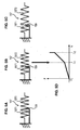
- FIGS. 5A to 5C schematically represent an example of a return member 156 for generating a double stiffness in a direction of rotation.
- the return member 156 comprises a spring 157 and a stopper 159.
- the spring 157 has a first spring portion 1571 and a second spring portion 1572 connected in series with the first spring portion 1572, the stopper 159 being interposed between a turn of the first spring portion 1571 and a turn of the second spring portion 1572.
- the Figures 5B and 5C represent the spring 157 when the lever 102 is biased by the pilot around the axis of rotation Y '.
- the spring 157 has been stretched by a first length Li.
- the two spring portions 1571 and 1572 have elongated until a turn of the first spring portion 1571 comes into play. against the stop 159. Once the turn of the first spring portion 1571 abuts against the stop 159, the first spring portion 1571 can no longer be elongated.
- the spring has been stretched by a second length L 2 , greater than the first length L 1 , but only the second spring portion 1572 has elongated, the first spring portion 1571 being neutralized by the stop 159.
- the figure 5D illustrates the intensity of the return force F generated by the return member 156 as a function of the elongation L of the spring 157. It can be seen that the force F generated follows a double slope force law. During the first phase, the two portions of spring are biased, so that the force generated has a linear variation having a first slope. During the second phase, only the second spring portion is biased, so that the force has a linear variation having a second slope; greater than the first slope.
- the ball joint 150 connecting the lever 102 to the frame 101 can be replaced by a universal joint 20.
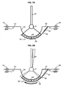
- the Figures 6A to 6C show schematically an example of gimbal system 21 that can be used to mount the handle 102 on the housing 101 of the mini 100. The system shown reduces the friction forces and eliminate any risk of seizure.
- the generally planar shape of the cardan system 21 shown frees space above the center of rotation 132 of the handle 102, which is particularly advantageous in a confined environment.
- the cardan system 21 shown on the Figures 6A to 6C comprises a flat base 22, a flat intermediate piece 23, and two support pieces 24 and 25.
- the flat base 22 is fixed to the frame 101 of the mini-board 100 and the handle 102 is fixed to the two support pieces 24 and 25:
- the cardan system 21 further comprises two flexible blades 26, 27 linking the base 22 to the intermediate part 23 and allowing a rotation of the intermediate part 23 relative to the base 22 plane according to a first axis of rotation (x axis).
- the cardan system 21 also comprises two flexible blades 28, 29 linking the intermediate piece 23 to the support pieces 24, 25 and allowing a rotation of the support pieces 24, 25 with respect to the intermediate piece 23 along a second axis of rotation ( y axis) perpendicular to the first axis of rotation.
- the handle 102 can be rotated relative to the housing according to the two axes of rotation x and y, these two axes of rotation being fixed relative to the frame 101.
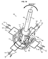
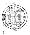
- FIGS. 7A to 7C schematically represent a mini-stick 200 according to a second embodiment of the invention.
- the sets of cradles 153, 163, 173 and 183 have been replaced by ball bearings 253, 263, 273, 283, each bearing comprising a handle ring 255, 265, 275, 285 and a ring built 254, 264, 274, 284.
- the minimium 200 comprises a frame 201, a handle 202 mounted to rotate with respect to the frame, and a mechanical assembly 203 for connecting the handle to the frame.
- the mechanical linking assembly 203 comprises two pairs of connecting pieces, including a first pair of connecting pieces 213, 223 and a second pair of connecting pieces 233, 243.
- Each connecting piece 213, 223 of the first pair is mounted to rotate relative to the frame 201 about a first axis of rotation (X axis) through first pivot links 210 and 220.
- each connecting piece 233, 243 of the second pair is mounted movably relative to the frame 201 about a second axis of rotation (Y axis) through second pivot links 230 and 240.
- the mechanical linkage assembly 203 also comprises four bearings 253, 263, 273 and 283, including a first pair of bearings 253, 263 and a second pair of bearings 273, 283.
- Each bearing comprises a handle ring and a housing ring.
- the housing ring 254, 264 is mounted integral with the first connecting pieces 213, 223, so that a rotation of the first connecting pieces 213, 223 around the first axis of rotation X leads to also a rotation of the bearings 253, 263.
- the handle ring 255, 265 is rotatably mounted relative to the housing ring 254, 264 according to a third axis of rotation (Y 'axis) perpendicular to the first axis of rotation ( X axis).
- the ring 274, 284 is mounted integral with the second connecting pieces 233, 243, so that a rotation of the second connecting pieces 233, 243 around the second axis of rotation Y also causes rotation of the bearings 273, 283.
- the handle ring 275, 285 is rotatably mounted relative to the frame ring 274, 284 along a fourth axis of rotation (axis X ') perpendicular to the second axis rotation (Y axis).
- lever rings 255, 265, 275 and 285 constitute intermediate parts of the mechanical linkage assembly 203 for linking the connecting pieces to the lever 202.
- the minimium 200 comprises a return member 256 extending between a connecting piece 223 and the handle ring 255, as in the first embodiment.
- the return member 256 is able to exert a return torque tending to oppose a rotation of the handle ring 255 relative to the ring 254, that is to say to oppose a rotation of the handle 202 relative to the frame 201.
- the return member 256 comprises a helical linear spring 257 and a ribbon 258 wound around a cylindrical surface portion 259 of the handle ring 255.
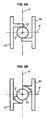
- the figure 8A illustrates the return member 256 when the joystick 202 is in the neutral position.
- the Figure 8B illustrates the return member 256 when the handle 202 is rotated about the axis Y 'in a first direction of rotation.
- the lever ring 255 rotated by the handle 202, does not cause the ribbon 258, which does not wrap around the cylinder portion of the handle ring 255, leaving unchanged the elongation of the spring 257.
- the Figure 8C illustrates the return member 256 when the handle 202 is rotated about the axis Y 'in a second direction of rotation, opposite to the first direction of rotation.
- the handle 202 rotates the handle ring 255, which has the effect of winding the tape 258 around the handle ring 255.
- the tape 258 exerts a pull on the spring 257 which elongates and generates a return force tending to oppose the rotation of the handle ring 255 with respect to the frame ring 254.
- each cradle handles 175 and 185 has a stop.
- the lower part 122 of the handle 102 is able to bear against a stop of a cradle 175 and handle 185 to rotate the cradle lever.
- the stops are arranged so that a rotation of the handle 102 along the fourth axis of rotation (axis X ') in a first direction causes a rotation of the cradle 175 relative to the cradle 174, without driving the cradle 185 lever rotation. Conversely, a rotation of the handle 102 along the fourth axis of rotation (axis X ') in a second direction, opposite to the first direction, causes a rotation of the cradle lever 185 relative to the cradle frame 184, without causing the cradle joystick 175 in rotation.
- the handle 102 is in contact with the stops in a rectilinear line of contact.
- the handle 202 is in contact with the stops along a cylindrical contact surface.
- the contact between the lever 102 and the stops allows a rotation of the lever 102 relative to the cradles 175 and lever 185 around the Z 'axis without causing any parasitic rotation of the cradles 175 and 185 relative to the cradles frame 174 and 184, which is essential not to generate coupling between the axes X 'and Y'.
- the figure 10 schematically represents a first variant of the Figures 7A to 7C .
- the pivots 220 and 210 are fixedly mounted on the frame 201, while the pivots 230 and 240 are rotatably mounted relative to the frame 201.
- the second connecting pieces 233 and 243 are rotatably mounted compared to the frame 201 around a fifth axis (Z axis), the fifth axis being perpendicular to the first axis (X axis) and the second axis (Y axis) and passing through the center of rotation O of the joystick 202.
- the mechanical linkage unit 203 comprises a fifth bearing 293 comprising an outer ring 294 fixedly mounted relative to the frame 201 and an inner ring 295 rotatably mounted relative to the outer ring 294 (and therefore with respect to the frame 201) about the Z axis.
- the connecting pieces 233 and 243 are rotatably mounted on the inner ring 295 about the Y axis through pivots 230 and 240.
- This arrangement allows a rotation of one of the fixed reference systems (Y defined by the connecting pieces 233 and 243) relative to the other fixed reference (X defined by the connecting pieces 213 and 223) around the Z axis , while the two axes X 'and Y' of the pivotal reference remain fixed and orthogonal with respect to each other.
- This arrangement allows a variation of the angle formed between the first axis of rotation X and the second axis of rotation Y, the first axis of rotation X being fixed relative to the frame 201.
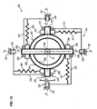
- the figure 11 schematically represents a second variant of the Figures 7A to 7C wherein the first axis of rotation X and the second axis of rotation Y are movable relative to the frame 201.
- the mechanical linkage assembly 203 comprises a fifth bearing 293 comprising an outer ring 294 and an inner ring 295, each of the rings 294 and 295 being rotatably mounted relative to the frame 201 about the Z axis.
- the mechanical linkage assembly 203 also comprises a plurality of rollers 296 interposed between the rings 294 and 295 and rotatably mounted by relative to the frame 201 about their axis, which are parallel to the Z axis and fixed relative to the frame 201.
- the rollers 296 make it possible to rotate the rings 294 and 295 in rotation so that a rotation of one of the rings relative to the frame 201 in one direction causes concomitantly a rotation of the other ring in the opposite direction of an identical angle. .
- This arrangement also allows a rotation of the fixed reference systems X and Y relative to each other (defined on the one hand by the connecting pieces 213 and 223 and on the other hand by the connecting pieces 233 and 243) around of the Z axis, while the two axes X 'and Y' of the pivotal reference remain fixed and orthogonal with respect to each other.
- This assembly thanks to this additional degree of freedom made indispensable by projection of the vectors rotations, also allows a displacement of the joystick 202 in rotation simultaneously along the first axis of rotation X and the second axis of rotation Y, and this without inducing rotation of the handle along the axis Z '.
- the figure 12 schematically represents a third variant of the Figures 7A to 7C wherein the bearings are rotatable.
- the bearings 253 and 263 are fixedly mounted relative to the handle 202, while the bearings 273 and 283 are rotatably mounted relative to the handle 202.
- the intermediate parts 275 and 285 (formed by the bearing bushes 273 and 283) are rotatably mounted relative to the handle 202.
- the fifth axis being perpendicular to the third axis (Y' axis) and the fourth axis ( X ') and passing through the center of rotation O of the joystick 202.
- the mechanical connection unit 203 comprises a fifth bearing 293 comprising an inner ring 295 fixed mounted relative to the handle 202 and an outer ring 294 mounted movable relative to the inner ring 295 (and therefore relative to the handle 202) about the axis Z '.
- the intermediate parts 275 and 285 are fixedly mounted on the outer ring 294 of the fifth bearing 293.
- This arrangement allows a rotation of the handle 202 relative to one of the pivotal references (defined by the connecting pieces 233 and 243) about the axis Z '(longitudinal axis of the handle 202).
- This arrangement allows a variation of the angle formed between the third axis of rotation Y 'and the fourth axis of rotation X', the third axis of rotation Y 'being fixed relative to the handle 202.
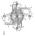
- the figure 13 schematically represents a fourth variant of the Figures 7A to 7C .
- This fourth variant has a functioning identical to that of the third variant. While the third variant allows the use of identical bearings 253, 263, 273 and 283, the fourth variant is more compact by including nested bearings.
- the outer ring 294 of the fifth bearing 293 is fixed to the internal lever rings 275 and 285 of the bearings 273 and 283 of the second pair.
- the inner ring 295 of the fifth bearing 293 is attached to the outer handle rings 255 and 265 of the bearings 253 and 263 of the first pair.
- the figure 14 schematically represents a fifth variant of the Figures 7A to 7C , wherein the fourth axis of rotation X 'and the third axis of rotation Y' are movable relative to the handle 202.
- the mechanical linkage assembly 203 comprises a fifth bearing 293 comprising an outer ring 294 and an inner ring 295, each of the rings 294 and 295 being rotatably mounted relative to the handle 202 about the axis Z '.
- the mechanical connection unit 203 also comprises a plurality of rollers 296 interposed between the rings 294 and 295 and rotatably mounted relative to the lever about their axes, which are parallel to the axis Z 'and fixed relative to the joystick 202.
- the rollers 296 make it possible to link the rings 294 and 295 in rotation so that a rotation of one of the rings relative to the lever 202 in one direction simultaneously causes a rotation of the other ring in the opposite direction of an angle. identical.
- This arrangement allows a rotation of the handle 202 with respect to each of the pivotal reference frames (the pivotal references being respectively defined by the connecting pieces 213 and 223 and by the connecting pieces 233 and 243) about the axis Z '.
- This assembly thanks to this additional degree of freedom made indispensable by projection of the vectors rotations, also allows a displacement of the joystick 202 in rotation simultaneously along the first axis of rotation X and the second axis of rotation Y, and this without inducing rotation of the handle along the axis Z '.
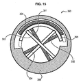
- the figure 15 schematically shows a connecting member 393 that can be used in the variant of the figure 14 instead of the fifth bearing 293 and the plurality of associated rollers 296.
- the link member 393 shown comprises a first portion 394, a second portion 395 and a third portion 396.
- the first portion 394 is movably mounted relative to the third portion 396.
- the second portion 395 is mounted movably relative to in the third part 396.
- the connecting member 393 also comprises two pairs of flexible blades 301 and 302, 303 and 304.
- Each flexible blade 301, 302 of first pair connects the first portion 394 and the third portion 396 between them and is elastically deformable to allow rotation of the third portion 396 relative to the first portion 394.
- the flexible blades 301 and 302 are adapted to generate a return torque tending to oppose the rotation of the parts 394 and 396 between them.
- each flexible blade 303, 304 of the second pair connects the second portion 395 and the third portion 396 between them and is elastically deformable to allow rotation of the third portion 396 relative to the second portion 395.
- the flexible blades 303, 304 are able to generate a return torque tending to oppose the rotation of the parts 395 and 396 between them.
- the first portion 394 is attached to the intermediate pieces 275 and 285.
- the second part 395 is attached to the intermediate parts 255 and 265.
- the third portion 396 is attached to the joystick 202.
- this assembly allows a rotation of the handle 202 relative to each of the pivotal reference frames (the pivotal references being defined respectively by the connecting pieces 213 and 223 and the connecting pieces 233 and 243) about the axis Z '.
- This assembly thanks to this additional degree of freedom made indispensable by projection of the vectors rotations, also allows a displacement of the joystick 202 in rotation simultaneously along the first axis of rotation X and the second axis of rotation Y, and this without inducing rotation of the handle along the axis Z '.
Landscapes
- Engineering & Computer Science (AREA)
- Automation & Control Theory (AREA)
- Aviation & Aerospace Engineering (AREA)
- Physics & Mathematics (AREA)
- General Physics & Mathematics (AREA)
- Mechanical Control Devices (AREA)
- Position Input By Displaying (AREA)
Description
L'invention concerne un minimanche de pilotage d'un aéronef.The invention relates to a piloting minimap of an aircraft.
Les aéronefs sont traditionnellement équipés de manche de pilotage permettant au pilote d'actionner les ailerons et la gouverne de profondeur afin de commander l'attitude de l'aéronef sur les axes de tangage et de roulis. Le manche de pilotage est positionné entre les jambes du pilote, qui se sert de la force de ses bras pour actionner le manche.The aircraft are traditionally equipped with a control stick allowing the pilot to operate the ailerons and the elevator in order to control the attitude of the aircraft on the pitch and roll axes. The control stick is positioned between the legs of the pilot, who uses the strength of his arms to operate the handle.
Dans certains avions équipés de commandes de vol électriques, le manche de pilotage a été remplacé par un dispositif de pilotage appelé « minimanche ». Plus compact qu'un manche de pilotage classique, le minimanche est généralement intégré dans un accoudoir du siège du pilote et comprend une manette que le pilote actionne par le seul mouvement de son poignet. L'installation de minimanches a permis de dégager l'espace situé entre le pilote et le tableau de bord afin d'y installer d'autres équipements. Une telle manche de pilotage est connue de
Par ailleurs, le minimanche inclut généralement un ensemble de ressorts permettant d'exercer un effort de rappel sur chacun des axes de rotation de la manette (axe de roulis et axe de tangage) et de ramener la manette en une position neutre lorsque le pilote n'exerce aucun effort sur la manette.Furthermore, the minimanche generally includes a set of springs for exerting a return force on each of the axes of rotation of the joystick (roll axis and pitch axis) and to return the lever to a neutral position when the pilot exerts no effort on the controller.
Toutefois, les structures mécaniques de minimanche existantes ne permettent généralement pas d'obtenir un découplage des efforts de rappel entre les deux axes de rotation de la manette. Autrement dit, l'effort de rappel exercé sur un axe de la manette dépend de la position angulaire de la manette selon l'autre axe.However, existing mechanical mini-structures do not generally allow to obtain a decoupling of the return forces between the two axes of rotation of the joystick. In other words, the return force exerted on one axis of the lever depends on the angular position of the lever along the other axis.
De plus, ces structures ne permettent pas non plus de générer des efforts de rappel linéaires (c'est-à-dire dont l'intensité est proportionnelle à la position angulaire de la manette selon l'axe de rotation considéré).In addition, these structures also do not allow to generate linear return forces (that is to say, whose intensity is proportional to the angular position of the lever according to the axis of rotation considered).
Un but de l'invention est de proposer une structure de minimanche permettant un découplage entre les efforts de rappel exercés sur chacun des axes.An object of the invention is to provide a structure for minimizing decoupling between the biasing forces exerted on each of the axes.
Ce problème est résolu dans le cadre de la présente invention grâce à un minimanche de pilotage d'un aéronef, comprenant un bâti, une manette montée mobile en rotation par rapport au bâti, et un ensemble mécanique de liaison de la manette au bâti, l'ensemble mécanique de liaison comprenant :
- une première pièce de liaison montée mobile par rapport au bâti autour d'un premier axe de rotation,
- une deuxième pièce de liaison montée mobile par rapport au bâti autour d'un deuxième axe de rotation, le deuxième axe de rotation formant un angle non-nul avec le premier axe de rotation,
- une troisième pièce intermédiaire montée mobile en rotation par rapport à la première pièce de liaison autour d'un troisième axe de rotation,
- une quatrième pièce intermédiaire montée mobile en rotation par rapport à la deuxième pièce de liaison autour d'un quatrième axe de rotation, le quatrième axe de rotation formant un angle non-nul avec le troisième axe de rotation,
- a first connecting piece mounted to move relative to the frame about a first axis of rotation,
- a second connecting piece mounted movable relative to the frame about a second axis of rotation, the second axis of rotation forming a non-zero angle with the first axis of rotation,
- a third intermediate piece mounted to rotate with respect to the first connecting piece around a third axis of rotation,
- a fourth intermediate piece rotatably mounted relative to the second connecting piece around a fourth axis of rotation, the fourth axis of rotation forming a non-zero angle with the third axis of rotation,
Grâce à la structure de minimanche proposée, il est possible d'exercer des efforts de rappel sur la première pièce de liaison et sur la deuxième pièce de liaison de manière totalement indépendante.Thanks to the proposed mini-structure, it is possible to exert restoring forces on the first connecting piece and the second connecting piece completely independently.
Par ailleurs, l'existence d'un cinquième axe de rotation autorise un désalignement entre le premier axe de rotation et le quatrième axe de rotation et/ou entre le deuxième axe de rotation et le troisième axe de rotation. Ce degré de liberté supplémentaire permet un déplacement de la manette en rotation simultanément selon le premier axe de rotation et selon le deuxième axe de rotation, malgré un désalignement se produisant entre les axes du référentiel fixe matérialisé par le bâti (premier et deuxième axes de rotation) et les axes des référentiels pivotants matérialisés par les pièces de liaison (troisième et quatrième axes).Moreover, the existence of a fifth axis of rotation allows a misalignment between the first axis of rotation and the fourth axis of rotation and / or between the second axis of rotation and the third axis of rotation. This additional degree of freedom allows a movement of the handle in rotation simultaneously along the first axis of rotation and the second axis of rotation, despite a misalignment occurring between the axes of the fixed reference materialized by the frame (first and second axes of rotation ) and the axes of the pivotal reference frames materialized by the connecting pieces (third and fourth axes).
Le minimanche selon l'invention peut en outre présenter les caractéristiques suivantes :
- l'ensemble mécanique de liaison comprend un organe de liaison comprenant une bague externe et une bague interne montées rotatives l'une par rapport à l'autre autour du cinquième axe de rotation, chacune des pièces de liaison ou respectivement des pièces intermédiaires étant reliée à une bague respective de l'organe de liaison, la manette étant solidaire de la troisième pièce intermédiaire et/ou de la quatrième pièce intermédiaire,
- l'une des bagues de l'organe de liaison est fixe par rapport à la première pièce de liaison et l'autre bague est fixe par rapport à la deuxième pièce de liaison,
- l'une des bagues de l'organe de liaison est fixe par rapport au bâti, de manière à autoriser une rotation seulement de la première pièce de liaison ou seulement de la deuxième pièce de liaison par rapport au bâti autour du cinquième axe de rotation,
- l'organe de liaison comprend au moins un galet monté rotatif autour d'un axe de rotation fixe par rapport au bâti, le galet étant interposé entre la bague interne et la bague externe de sorte qu'une rotation de l'une des bagues par rapport au bâti entraine concomitamment une rotation en sens opposé de l'autre bague par rapport au bâti,
- l'une des bagues de l'organe de liaison est fixe par rapport à la troisième pièce intermédiaire et l'autre bague est fixe par rapport à la quatrième pièce intermédiaire,
- l'une des bagues de l'organe de liaison est fixe par rapport à la manette, de manière à autoriser une rotation de la manette seulement par rapport à la troisième pièce intermédiaire ou seulement par rapport à la quatrième pièce intermédiaire autour du cinquième axe de rotation,
- l'organe de liaison comprend au moins un galet monté rotatif autour d'un axe de rotation fixe par rapport à la manette, le galet étant interposé entre la bague interne et la bague externe de sorte qu'une rotation de l'une des bagues par rapport à la manette entraine concomitamment une rotation en sens opposé de l'autre bague par rapport à la manette,
- l'ensemble mécanique de liaison comprend un organe de liaison comprenant une partie fixe et une partie montée mobile par rapport à la partie fixe, l'organe de liaison comprenant au moins deux lames flexibles, chaque lame flexible reliant les parties entre elles et étant déformable élastiquement pour autoriser une rotation de la partie mobile par rapport à la partie fixe, les lames flexibles étant aptes à générer un couple de rappel tendant à s'opposer à la rotation des parties entre elles,
- la troisième pièce intermédiaire ou la quatrième pièce intermédiaire est fixée à une partie de l'organe de liaison et la manette est fixée à l'autre partie de l'organe de liaison,
- la manette est reliée au bâti par une liaison rotule autorisant une rotation de la manette selon les trois axes de rotation par rapport au bâti,
- la manette est reliée au bâti par une liaison cardan autorisant seulement une rotation de la manette selon le premier axe et une rotation de la manette selon le deuxième axe par rapport au bâti,
- la manette est apte à venir en appui simple sur la troisième pièce intermédiaire et sur la quatrième pièce intermédiaire pour solliciter les pièces intermédiaires en rotation respectivement selon les troisième et quatrième axes, de manière à autoriser une rotation relative des pièces intermédiaires par rapport à la manette selon le cinquième axe de rotation,
- l'une des pièces intermédiaires comprend une butée agencée de sorte que la manette est apte à venir en appui sur la butée pour solliciter la pièce intermédiaire et provoquer la rotation de la pièce intermédiaire dans un seul sens de sollicitation,
- la manette est apte à venir en appui sur la butée selon une ligne de contact rectiligne, parallèle au cinquième axe de rotation,
- la manette est apte à venir en appui sur la butée selon une surface de contact cylindrique, ayant un axe de révolution parallèle au cinquième axe de rotation,
- le minimanche comprend un organe de rappel apte à solliciter l'une des pièces intermédiaires de l'organe de liaison pour s'opposer à la rotation de la pièce intermédiaire,
- l'organe de rappel comprend un ressort de traction reliant la première pièce de liaison ou la deuxième pièce de liaison à la pièce intermédiaire qui est entrainée en rotation sous l'action de la manette,
- l'organe de rappel comprend un ruban reliant le ressort de traction et la pièce intermédiaire, le ruban étant apte à s'enrouler autour d'un élément cylindrique et solidaire de la pièce intermédiaire.
- the mechanical connection assembly comprises a connecting member comprising an outer ring and an inner ring rotatably mounted relative to one another about the fifth axis of rotation, each of the connecting pieces or the intermediate pieces being connected to a respective ring of the connecting member, the lever being secured to the third intermediate piece and / or the fourth intermediate piece,
- one of the rings of the connecting member is fixed relative to the first connecting piece and the other ring is fixed relative to the second connecting piece,
- one of the rings of the connecting member is fixed relative to the frame, so as to allow rotation only of the first connecting piece or only of the second connecting piece relative to the frame about the fifth axis of rotation,
- the connecting member comprises at least one roller rotatably mounted about a fixed axis of rotation relative to the frame, the roller being interposed between the inner ring and the outer ring so that a rotation of one of the rings by relative to the frame simultaneously causes rotation in the opposite direction of the other ring relative to the frame,
- one of the rings of the connecting member is fixed with respect to the third intermediate piece and the other ring is fixed with respect to the fourth intermediate piece,
- one of the rings of the connecting member is fixed relative to the handle, so as to allow rotation of the lever only relative to the third intermediate piece or only relative to the fourth intermediate piece around the fifth axis of rotation,
- the connecting member comprises at least one roller rotatably mounted about a fixed axis of rotation relative to the lever, the roller being interposed between the inner ring and the outer ring so that a rotation of one of the rings relative to the handle simultaneously causes rotation in the opposite direction of the other ring relative to the handle,
- the mechanical connection assembly comprises a connecting member comprising a fixed part and a part mounted to move relative to the fixed part, the connecting member comprising at least two flexible blades, each flexible blade connecting the parts between them and being deformable elastically to allow a rotation of the mobile part relative to the fixed part, the flexible blades being able to generate a return torque tending to oppose the rotation of the parts between them,
- the third intermediate piece or the fourth intermediate piece is fixed to a part of the connecting member and the handle is fixed to the other part of the connecting member,
- the handle is connected to the frame by a ball joint allowing a rotation of the handle according to the three axes of rotation relative to the frame,
- the handle is connected to the frame by a cardan link allowing only a rotation of the handle according to the first axis and a rotation of the handle along the second axis relative to the frame,
- the lever is able to come in simple support on the third intermediate part and on the fourth intermediate part to urge the intermediate parts in rotation respectively along the third and fourth axes, so as to allow relative rotation of the intermediate parts relative to the lever according to the fifth axis of rotation,
- one of the intermediate parts comprises an abutment arranged so that the handle is able to bear against the abutment to urge the intermediate piece and cause rotation of the intermediate piece in a single direction of stress,
- the lever is able to bear against the abutment in a rectilinear contact line, parallel to the fifth axis of rotation,
- the lever is able to bear against the abutment along a cylindrical contact surface, having an axis of revolution parallel to the fifth axis of rotation,
- the minimap comprises a return member adapted to urge one of the intermediate parts of the connecting member to oppose the rotation of the intermediate piece,
- the return member comprises a tension spring connecting the first connecting piece or the second connecting piece to the intermediate piece which is rotated by the action of the handle,
- the return member comprises a ribbon connecting the tension spring and the intermediate piece, the ribbon being able to wind around a cylindrical member and secured to the intermediate piece.
D'autres caractéristiques et avantages ressortiront encore de la description qui suit, laquelle est purement illustrative et non limitative, et doit être lue en regard des figures annexées, parmi lesquelles :
- les
figures 1A et1B représentent de manière schématique un minimanche selon un premier mode de réalisation de l'invention avec des berceaux, - les
figures 2A et 2B représentent de manière schématique l'action d'un organe de rappel sur une bague externe d'un berceau du minimanche, - la
figure 3 représente de manière schématique l'agencement d'un organe de rappel sur une bague interne d'un berceau du minimanche, - les
figures 4A et 4B représentent de manière schématique l'agencement de deux organes de rappel sur les bagues internes de deux berceaux, - les
figures 5A à 5D représentent de manière schématique un organe de rappel présentant une double raideur, - les
figures 6A à 6C représentent de manière schématique un exemple de système à cardan pouvant être utilisé pour monter la manette sur le boîtier du minimanche, - les
figures 7A à 7C représentent de manière schématique un minimanche selon un deuxième mode de réalisation de l'invention avec des roulements, - les
figures 8A à 8C représentent de manière schématique une fixation de l'organe de rappel à une bague d'un roulement, - les
figures 9A et 9B représentent de manière schématique deux exemples de contact entre la manette et les berceaux pour une réalisation du minimanche desfigures 1A et1B , - la
figure 10 représente de manière schématique une première variante du minimanche desfigures 7A à 7C , - la
figure 11 représente de manière schématique une deuxième variante du minimanche desfigures 7A à 7C , - la
figure 12 représente de manière schématique une troisième variante du minimanche desfigures 7A à 7C , - la
figure 13 représente de manière schématique une quatrième variante du minimanche desfigures 7A à 7C , - la
figure 14 représente de manière schématique une cinquième variante du minimanche desfigures 7A à 7C , - la
figure 15 représente de manière schématique un organe de liaison pouvant être utilisé dans les variantes desfigures 12 ,13 et14 à la place du cinquième roulement.
- the
Figures 1A and1B schematically represent a minimalism according to a first embodiment of the invention with cradles, - the
Figures 2A and 2B schematically represent the action of a return member on an outer ring of a cradle of the mini-stick, - the
figure 3 schematically represents the arrangement of a return member on an inner ring of a cradle of the mini-stick, - the
Figures 4A and 4B schematically represent the arrangement of two return members on the inner rings of two cradles, - the
Figures 5A to 5D schematically represent a return member having a double stiffness, - the
Figures 6A to 6C schematically represent an example of a cardan system that can be used to mount the handle on the housing of the mini-board, - the
Figures 7A to 7C schematically represent a mini-stick according to a second embodiment of the invention with bearings, - the
Figures 8A to 8C schematically represent an attachment of the return member to a ring of a bearing, - the
Figures 9A and 9B schematically represent two examples of contact between the controller and the cradles for a realization of theFigures 1A and1B , - the
figure 10 schematically represents a first variant of theFigures 7A to 7C , - the
figure 11 schematically represents a second variant of theFigures 7A to 7C , - the
figure 12 schematically represents a third variant of theFigures 7A to 7C , - the
figure 13 schematically represents a fourth variant of theFigures 7A to 7C , - the
figure 14 schematically represents a fifth variant of theFigures 7A to 7C , - the
figure 15 schematically represents a connecting member that can be used in the variants offigures 12 ,13 and14 instead of the fifth bearing.
Les
Le minimanche 100 comprend un bâti 101 destiné par exemple à être intégré dans un accoudoir d'un siège, une manette 102 montée mobile en rotation par rapport au bâti, et un ensemble mécanique 103 de liaison de la manette au bâti permettant de générer un retour d'effort sur la manette selon deux axes de rotation.The mini-stick 100 comprises a
La manette 102 présente une forme générale allongée selon une direction longitudinale (axe Z'). Plus précisément, la manette 102 comprend une partie supérieure allongée 112 destinée à être saisie par la main du pilote, une partie inférieure allongée 122 apte à coopérer avec l'ensemble mécanique de liaison 103, et une partie intermédiaire 132 présentant une surface externe sphérique 142.The
Le bâti 101 comprend une partie de support présentant une surface interne sphérique 111 recevant la partie intermédiaire 132 de la manette 102. La manette 102 est ainsi reliée au bâti 101 par une liaison rotule 150 constituée par la surface externe sphérique 142 de la partie intermédiaire 132 de la manette 102 et la surface interne sphérique 111 complémentaire de la partie de support du bâti 101.The
L'ensemble mécanique de liaison 103 comprend deux paires de pièces de liaison, incluant une première paire de pièces de liaison 113, 123 et une deuxième paire de pièce de liaison 133,143.The
Chaque pièce de liaison 113, 123 de la première paire est montée mobile en rotation par rapport au bâti 101 autour d'un premier axe de rotation (axe X) par le biais de premières liaisons pivot 110 et 120.Each connecting
De même, chaque pièce de liaison 133, 143 de la deuxième paire est montée mobile par rapport au bâti 101 autour d'un deuxième axe de rotation (axe Y) par le biais de deuxièmes liaisons pivot 130 et 140.Similarly, each connecting
Lorsque le minimanche 100 est en position de neutre (c'est-à-dire que le pilote n'exerce aucune sollicitation sur la manette 102), le deuxième axe de rotation (axe Y) est perpendiculaire au premier axe de rotation (axe X). De plus, le premier axe de rotation et le deuxième axe de rotation se coupent en un point d'intersection O qui est également le centre de rotation de la manette 102 par rapport au bâti 101, centre de la liaison rotule 150 (représenté déporté sur la figure selon l'axe Z' dans le seul but de dégager la vue des pièces sur le dessin).When the mini-stick 100 is in the neutral position (that is to say that the pilot exerts no stress on the handle 102), the second axis of rotation (Y axis) is perpendicular to the first axis of rotation (X axis ). In addition, the first axis of rotation and the second axis of rotation intersect at a point of intersection O which is also the center of rotation of the
L'ensemble mécanique de liaison 103 comprend également quatre ensembles de berceaux 153, 163, 173 et 183, incluant deux premiers ensembles de berceaux 153, 163 et deux deuxièmes ensembles de berceaux 173, 183. Chaque ensemble de berceaux comprend un berceau bâti et un berceau manette.The
Dans chaque premier ensemble de berceaux 153, 163, le berceau bâti 154, 164 est monté solidaire des premières pièces de liaison 113, 123, de sorte qu'une rotation des premières pièces de liaison 113, 123 autour du premier axe de rotation X entraine également une rotation des premiers ensembles de berceaux 153, 163. De plus, le berceau manette 155, 165 est monté mobile en rotation par rapport au berceau bâti 154, 164 selon un troisième axe de rotation (axe Y') perpendiculaire au premier axe de rotation (axe X).In each first set of
De même, dans chaque deuxième ensemble de berceaux 173, 183, le berceau bâti 174, 184 est monté solidaire des deuxièmes pièces de liaison 133, 143, de sorte qu'une rotation des deuxièmes pièces de liaison 133, 143 autour du deuxième axe de rotation Y entraine également une rotation des deuxièmes ensembles de berceaux 173, 183. De plus, le berceau manette 175, 185 est monté mobile en rotation par rapport au berceau externe 174, 184 selon un quatrième axe de rotation (axe X') perpendiculaire au deuxième axe de rotation (axe Y).Similarly, in each second set of
Dans ce premier mode de réalisation, les berceaux manette 155, 165, 175 - et 185 constituent des pièces intermédiaires de l'ensemble mécanique de liaison 103 pour lier les pièces de liaison à la manette 102.In this first embodiment, the lever cradles 155, 165, 175 and 185 constitute intermediate parts of the
Plus précisément, dans chaque premier ensemble de berceaux 153, 163, le berceau manette 155, 165 est apte à être entrainé en rotation par rapport au berceau bâti 154, 164 (et par conséquent par rapport à la première pièce de liaison) sous l'action de la manette 102 autour du troisième axe de rotation. Comme cela est visible sur la
De même, dans chaque deuxième ensemble de berceaux 173, 183, le berceau manette 175, 185 est apte à être entrainé en rotation par rapport au berceau bâti 174, 184 (et par conséquent par rapport à la deuxième pièce de liaison) sous l'action de la manette 102 autour du quatrième axe de rotation. Comme cela est visible sur la
C'est pourquoi, les ensembles de berceaux 153, 163, 173, 183 constituent pour la manette 102 des référentiels pivotants par rapport au référentiel fixe défini par le bâti 101.This is why the sets of
Comme cela est illustré sur les
Le ruban 158 présente une première extrémité fixée à la portion de surface cylindrique et une deuxième extrémité fixée à une deuxième extrémité du ressort. Le ressort 157 présente une première extrémité fixée à la pièce de liaison et une deuxième extrémité fixée à la deuxième extrémité du ruban. Comme cela est illustré sur la
Sur les
Les
Sur ces figures, seuls les deuxièmes pièces de liaison 133, 143 et les deuxièmes ensembles de berceaux 173, 183 ont été représentés. Toutefois, le même montage est réalisé pour les premières pièces de liaison 113, 123 et les premiers ensembles de berceaux 153, 163.In these figures, only the second connecting
Comme cela apparaît sur les
Les protubérances et les butées sont agencées de sorte qu'une rotation de la manette 102 selon le quatrième axe de rotation (axe X') dans un premier sens entraine une rotation du berceau manette 175 par rapport au berceau bâti 174, sans entraîner le berceau manette 185 en rotation. A l'inverse, une rotation de la manette 102 selon le quatrième axe de rotation (axe X') dans un deuxième sens, opposé au premier sens, entraine une rotation du berceau manette 185 par rapport au berceau bâti 184, sans entrainer le berceau manette 175 en rotation.The protuberances and the stops are arranged so that a rotation of the
Comme chaque berceau manette 155, 165, 175, 185 est muni de son propre organe de rappel, il est possible de prévoir des organes de rappel 156, 166, 176, 186 présentant des caractéristiques différentes, afin d'obtenir un retour d'effort différent selon le sens de sollicitation de la manette autour de l'axe X' et de l'axe Y'.Since each
Par ailleurs, le montage proposé permet de faire travailler les organes de rappel 156, 166, 176, 186 uniquement en traction, de sorte qu'aucun dispositif de guidage des organes de rappel n'est nécessaire et que tout risque de flambement des éléments constituant ces organes de rappel, que ce soit le ruban 158 ou le ressort linéique hélicoïdal 157, est éliminé.Moreover, the proposed assembly makes it possible to work the
De plus, ce montage permet de concevoir un minimanche 100 dans lequel les organes de rappel 156, 166, 176, 186 sont montés en étant précontraints en traction, c'est-à-dire que chaque organe de rappel 156, 166, 176, 186 exerce un effort de rappel non-nul sur la manette 102 lorsque la manette 102 est en position neutre. Cela permet de créer un seuil d'effort devant être vaincu lors de l'initialisation du déplacement de la manette.In addition, this arrangement makes it possible to design a mini-stick 100 in which the
Les
A cet effet, l'organe de rappel 156 comprend un ressort 157 et une butée 159. Le ressort 157 présente une première portion de ressort 1571 et une deuxième portion de ressort 1572 montée en série avec la première portion de ressort 1572, la butée 159 étant intercalée entre une spire de la première portion de ressort 1571 et une spire de la deuxième portion de ressort 1572.For this purpose, the
Sur la
Les
Sur la
Sur la
La
Dans une variante du premier mode de réalisation, la liaison rotule 150 reliant la manette 102 au bâti 101 peut être remplacée par une liaison cardan 20. Les
Le système de cardan 21 représenté sur les
Le système de cardan 21 comprend en outre deux lames flexibles 26, 27 liant la base 22 à la pièce intermédiaire 23 et autorisant une rotation de la pièce intermédiaire 23 par rapport à la base 22 plane selon un premier axe de rotation (axe x).The
Le système de cardan 21 comprend également deux lames flexibles 28, 29 liant la pièce intermédiaire 23 aux pièces de support 24, 25 et autorisant une rotation des pièces de support 24, 25 par rapport à la pièce intermédiaire 23 selon un deuxième axe de rotation (axe y) perpendiculaire au premier axe de rotation.The
De cette manière, la manette 102 peut être entrainée en rotation par rapport au boîtier selon les deux axes de rotation x et y, ces deux axes de rotation étant fixes par rapport au bâti 101.In this way, the
Les
Dans ce deuxième mode de réalisation, les ensembles de berceaux 153, 163, 173 et 183 ont été remplacés par des roulements à billes 253, 263, 273, 283, chaque roulement comprenant une bague manette 255, 265, 275, 285 et une bague bâti 254, 264, 274, 284.In this second embodiment, the sets of
Sur les
L'ensemble mécanique de liaison 203 comprend deux paires de pièces de liaison, incluant une première paire de pièces de liaison 213, 223 et une deuxième paire de pièce de liaison 233, 243.The
Chaque pièce de liaison 213, 223 de la première paire est montée mobile en rotation par rapport au bâti 201 autour d'un premier axe de rotation (axe X) par le biais de premières liaisons pivot 210 et 220.Each connecting
De même, chaque pièce de liaison 233, 243 de la deuxième paire est montée mobile par rapport au bâti 201 autour d'un deuxième axe de rotation (axe Y) par le biais de deuxièmes liaisons pivot 230 et 240.Similarly, each connecting
L'ensemble mécanique de liaison 203 comprend également quatre roulements 253, 263, 273 et 283, incluant un premier couple de roulements 253, 263 et un deuxième couple de roulements 273, 283. Chaque roulement comprend une bague manette et une bague bâti.The
Dans chaque roulement 253, 263 du premier couple, la bague bâti 254, 264 est montée solidaire des premières pièces de liaison 213, 223, de sorte qu'une rotation des premières pièces de liaison 213, 223 autour du premier axe de rotation X entraine également une rotation des roulements 253, 263. De plus, la bague manette 255, 265 est montée mobile en rotation par rapport à la bague bâti 254, 264 selon un troisième axe de rotation (axe Y') perpendiculaire au premier axe de rotation (axe X).In each bearing 253, 263 of the first pair, the
De même, dans chaque roulement 273, 283 du deuxième couple, la bague bâti 274, 284 est montée solidaire des deuxièmes pièces de liaison 233, 243, de sorte qu'une rotation des deuxièmes pièces de liaison 233, 243 autour du deuxième axe de rotation Y entraine également une rotation des roulements 273, 283. De plus, la bague manette 275, 285 est montée mobile en rotation par rapport à la bague bâti 274, 284 selon un quatrième axe de rotation (axe X') perpendiculaire au deuxième axe de rotation (axe Y).Similarly, in each bearing 273, 283 of the second pair, the
Dans ce deuxième mode de réalisation, les bagues manette 255, 265, 275 et 285 constituent des pièces intermédiaires de l'ensemble mécanique de liaison 203 pour lier les pièces de liaison à la manette 202.In this second embodiment, the lever rings 255, 265, 275 and 285 constitute intermediate parts of the
Comme cela est illustré sur les
La
La
La
Les
Les butées sont agencées de sorte qu'une rotation de la manette 102 selon le quatrième axe de rotation (axe X') dans un premier sens entraine une rotation du berceau manette 175 par rapport au berceau bâti 174, sans entrainer le berceau manette 185 en rotation. A l'inverse, une rotation de la manette 102 selon le quatrième axe de rotation (axe X') dans un deuxième sens, opposé au premier sens, entraine une rotation du berceau manette 185 par rapport au berceau bâti 184, sans entrainer le berceau manette 175 en rotation.The stops are arranged so that a rotation of the
Sur la
On notera que le montage alternatif des
La
Dans cette première variante, les pivots 220 et 210 sont montés fixes sur la bâti 201, tandis que les pivots 230 et 240 sont montés rotatifs par rapport au bâti 201. Autrement dit, les deuxièmes pièces de liaison 233 et 243 sont montées mobiles en rotation par rapport au bâti 201 autour d'un cinquième axe (axe Z), le cinquième axe étant perpendiculaire au premier axe (axe X) et au deuxième axe (axe Y) et passant par le centre de rotation O de la manette 202.In this first variant, the
A cet effet, l'ensemble mécanique de liaison 203 comprend un cinquième roulement 293 comprenant une bague externe 294 montée fixe par rapport au bâti 201 et une bague interne 295 montée mobile en rotation par rapport à la bague externe 294 (et donc par rapport au bâti 201) autour de l'axe Z. Les pièces de liaison 233 et 243 sont montées rotatives sur la bague interne 295 autour de l'axe Y par le biais des pivots 230 et 240.For this purpose, the
Ce montage autorise une rotation de l'un des référentiels fixe (Y défini par les pièces de liaison 233 et 243) par rapport à l'autre référentiel fixe (X défini par les pièces de liaison 213 et 223) autour de l'axe Z, alors que les deux axes X' et Y' du référentiel pivotant restent fixent et orthogonaux l'un par rapport à l'autre.This arrangement allows a rotation of one of the fixed reference systems (Y defined by the connecting
Ce montage autorise une variation de l'angle formé entre le premier axe de rotation X et lé deuxième axe de rotation Y, le premier axe de rotation X étant fixe par rapport au bâti 201.This arrangement allows a variation of the angle formed between the first axis of rotation X and the second axis of rotation Y, the first axis of rotation X being fixed relative to the
Grâce à ce montage, un désalignement entre le deuxième axe de rotation Y et le troisième axe de rotation Y' est possible. Ce degré de liberté supplémentaire, rendu indispensable par projection des vecteurs rotations, permet un déplacement de la manette 202 en rotation simultanément selon le premier axe de rotation X et selon le deuxième axe de rotation Y.With this arrangement, a misalignment between the second axis of rotation Y and the third axis of rotation Y 'is possible. This additional degree of freedom, made indispensable by projection of the vectors rotations, allows a displacement of the
La
Dans cette deuxième variante, l'ensemble mécanique de liaison 203 comprend un cinquième roulement 293 comprenant une bague externe 294 et une bague interne 295, chacune des bagues 294 et 295 étant montée mobile en rotation par rapport au bâti 201 autour de l'axe Z. L'ensemble mécanique de liaison 203 comprend également une pluralité de galets 296 interposés entre les bagues 294 et 295 et montés mobiles en rotation par rapport au bâti 201 autour de leur axe, lesquels sont parallèles à l'axe Z et fixes par rapport au bâti 201.In this second variant, the
Les galets 296 permettent de lier en rotation les bagues 294 et 295 de sorte qu'une rotation de l'une des bagues par rapport au bâti 201 dans un sens entraine concomitamment une rotation de l'autre bague en sens opposé d'un angle identique.The
Ce montage autorise également une rotation des référentiels fixes X et Y l'un par rapport à l'autre (défini d'une part par les pièces de liaison 213 et 223 et d'autre part par les pièces de liaison 233 et 243) autour de l'axe Z, alors que les deux axes X' et Y' du référentiel pivotant restent fixent et orthogonaux l'un par rapport à l'autre.This arrangement also allows a rotation of the fixed reference systems X and Y relative to each other (defined on the one hand by the connecting
Grâce à ce montage, un désalignement entre le premier axe de rotation X et le quatrième axe de rotation X' d'une part, et entre le deuxième axe de rotation Y et le troisième axe de rotation Y' d'autre part, est possible, les désalignements étant symétriques.With this arrangement, a misalignment between the first axis of rotation X and the fourth axis of rotation X 'on the one hand, and between the second axis of rotation Y and the third axis of rotation Y' on the other hand, is possible misalignments being symmetrical.
Ce montage, grâce à ce degré de liberté supplémentaire rendu indispensable par projection des vecteurs rotations, permet également un déplacement de la manette 202 en rotation simultanément selon le premier axe de rotation X et selon le deuxième axe de rotation Y, et ceci sans induire de rotation de la manette selon l'axe Z'.This assembly, thanks to this additional degree of freedom made indispensable by projection of the vectors rotations, also allows a displacement of the
La
Dans cette troisième variante, les roulements 253 et 263 sont montés fixes par rapport à la manette 202, tandis que les roulements 273 et 283 sont montés rotatifs par rapport à la manette 202. Autrement dit, les pièces intermédiaires 275 et 285 (formées par les bagues mobiles des roulements 273 et 283) sont montées mobiles en rotation par rapport à la manette 202. autour d'un cinquième axe (axe Z'), le cinquième axe étant perpendiculaire au troisième axe (axe Y') et au quatrième axe (axe X') et passant par le centre de rotation O de la manette 202.In this third variant, the
A cet effet, l'ensemble mécanique de liaison 203 comprend un cinquième roulement 293 comprenant une bague interne 295 montée fixe par rapport à la manette 202 et une bague externe 294 montée mobile par rapport à la bague interne 295 (et donc par rapport à la manette 202) autour de l'axe Z'. Les pièces intermédiaires 275 et 285 sont montées fixes sur la bague externe 294 du cinquième roulement 293.For this purpose, the
Ce montage autorise une rotation de la manette 202 par rapport à l'un des référentiels pivotants (défini par les pièces de liaison 233 et 243) autour de l'axe Z' (axe longitudinal de la manette 202).This arrangement allows a rotation of the
Ce montage autorise une variation de l'angle formé entre le troisième axe de rotation Y' et le quatrième axe de rotation X', le troisième axe de rotation Y' étant fixe par rapport à la manette 202.This arrangement allows a variation of the angle formed between the third axis of rotation Y 'and the fourth axis of rotation X', the third axis of rotation Y 'being fixed relative to the
Grâce à ce montage, un désalignement entre le troisième axe de rotation Y' et le deuxième axe de rotation Y est possible. Ce degré de liberté supplémentaire, rendu indispensable par projection des vecteurs rotations, permet un déplacement de la manette 202 en rotation simultanément selon le premier axe de rotation X et selon le deuxième axe de rotation Y.With this arrangement, a misalignment between the third axis of rotation Y 'and the second axis of rotation Y is possible. This additional degree of freedom, made indispensable by projection of the vectors rotations, allows a displacement of the
La
Dans cette quatrième variante, la bague externe 294 du cinquième roulement 293 est fixée aux bagues manette internes 275 et 285 des roulements 273 et 283 de la deuxième paire.In this fourth variant, the
La bague interne 295 du cinquième roulement 293 est fixée aux bagues manette externes 255 et 265 des roulements 253 et 263 de la première paire.The
La
Dans cette cinquième variante, l'ensemble mécanique de liaison 203 comprend un cinquième roulement 293 comprenant une bague externe 294 et une bague interne 295, chacune des bagues 294 et 295 étant montée mobile en rotation par rapport à la manette 202 autour de l'axe Z'. L'ensemble mécanique de liaison 203 comprend également une pluralité de galets 296 interposés entre les bagues 294 et 295 et montés mobile en rotation par rapport à la manette autour de leurs axes, lesquels sont parallèles à l'axe Z' et fixes par rapport à la manette 202.In this fifth variant, the
Les galets 296 permettent de lier en rotation les bagues 294 et 295 de sorte qu'une rotation de l'une des bagues par rapport à la manette 202 dans un sens entraine concomitamment une rotation de l'autre bague en sens opposé d'un angle identique.The
Ce montage autorise une rotation de la manette 202 par rapport à chacun des référentiels pivotants (les référentiels pivotants étant définis respectivement par les pièces de liaison 213 et 223 et par les pièces de liaison 233 et 243) autour de l'axe Z'.This arrangement allows a rotation of the
Grâce à ce montage, un désalignement entre le premier axe de rotation X et le quatrième axe de rotation X' d'une part, et entre le deuxième axe de rotation Y et le troisième axe de rotation Y' d'autre part, est possible, les désalignements étant symétriques.With this arrangement, a misalignment between the first axis of rotation X and the fourth axis of rotation X 'on the one hand, and between the second axis of rotation Y and the third axis of rotation Y' on the other hand, is possible misalignments being symmetrical.
Ce montage, grâce à ce degré de liberté supplémentaire rendu indispensable par projection des vecteurs rotations, permet également un déplacement de la manette 202 en rotation simultanément selon le premier axe de rotation X et selon le deuxième axe de rotation Y, et ceci sans induire de rotation de la manette selon l'axe Z'.This assembly, thanks to this additional degree of freedom made indispensable by projection of the vectors rotations, also allows a displacement of the
La
L'organe de liaison 393 représenté comprend une première partie 394, une deuxième partie 395 et une troisième partie 396. La première partie 394 est montée mobile par rapport à la troisième partie 396. De même, la deuxième partie 395 est montée mobile par rapport à la troisième partie 396.The
L'organe de liaison 393 comprend également deux couples de lames flexibles 301 et 302, 303 et 304. Chaque lame flexible 301, 302 du premier couple relie la première partie 394 et la troisième partie 396 entre elles et est déformable élastiquement pour autoriser une rotation de la troisième partie 396 par rapport à la première partie 394. Les lames flexibles 301 et 302 sont aptes à générer un couple de rappel tendant à s'opposer à la rotation des parties 394 et 396 entre elles.The connecting
De même, chaque lame flexible 303, 304 du deuxième couple relie la deuxième partie 395 et la troisième partie 396 entre elles et est déformable élastiquement pour autoriser une rotation de la troisième partie 396 par rapport à la deuxième partie 395. Les lames flexibles 303, 304 sont aptes à générer un couple de rappel tendant à s'opposer à la rotation des parties 395 et 396 entre elles.Similarly, each
La première partie 394 est fixée aux pièces intermédiaires 275 et 285.The
La deuxième partie 395 est fixée aux pièces intermédiaires 255 et 265.The
La troisième partie 396 est fixée à la manette 202.The
Comme dans le cas du minimanche, de la
Grâce à ce montage, un désalignement entre le premier axe de rotation X et le quatrième axe de rotation X' d'une part, et entre le deuxième axe de rotation Y et le troisième axe de rotation Y' d'autre part, est possible, les désalignements étant symétriques.With this arrangement, a misalignment between the first axis of rotation X and the fourth axis of rotation X 'on the one hand, and between the second axis of rotation Y and the third axis of rotation Y' on the other hand, is possible misalignments being symmetrical.
Ce montage, grâce à ce degré de liberté supplémentaire rendu indispensable par projection des vecteurs rotations, permet également un déplacement de la manette 202 en rotation simultanément selon le premier axe de rotation X et selon le deuxième axe de rotation Y, et ceci sans induire de rotation de la manette selon l'axe Z'.This assembly, thanks to this additional degree of freedom made indispensable by projection of the vectors rotations, also allows a displacement of the
- 100100
- Minimanche (premier mode de réalisation)Minimanche (first embodiment)
- 101101
- Bâtibuilt
- 102102
- ManetteController
- 103103
- Ensemble mécanique de liaisonMechanical linkage assembly
- 110110
- Liaison pivot (axe X)Pivot link (X axis)
- 111111
- Surface interne sphériqueSpherical inner surface
- 112112
- Partie supérieure de la manetteUpper part of the controller
- 113113
- Pièce de liaison (première paire)Connecting piece (first pair)
- 120120
- Liaison pivot (axe X)Pivot link (X axis)
- 122122
- Partie inférieure de la manetteLower part of the controller
- 123123
- Pièce de liaison (première paire)Connecting piece (first pair)
- 130130
- Liaison pivot (axe Y)Pivot connection (Y axis)
- 132132
- Partie intermédiaire de la manetteIntermediate part of the joystick
- 133133
- Pièce de liaison (deuxième paire)Connecting piece (second pair)
- 140140
- Liaison pivot (axe Y)Pivot connection (Y axis)
- 142142
- Surface externe sphériqueSpherical outer surface
- 143143
- Pièce de liaison (deuxième paire)Connecting piece (second pair)
- 150150
- Liaison rotulePatella connection
- 152152
- ProtubéranceProtuberance
- 153153
- Ensemble de berceaux (premiers ensembles)Set of cradles (first sets)
- 154154
- Berceau bâtiCradle built
- 155155
- Berceau manetteCradle joystick
- 156156
- Organe de rappelBody reminder
- 157157
- Ressort linéique hélicoïdalSpiral linear spring
- 158158
- RubanRibbon
- 159159
- Butéestopper
- 162162
- ProtubéranceProtuberance
- 163163
- Ensemble de berceaux (premiers ensembles)Set of cradles (first sets)
- 164164
- Berceau bâtiCradle built
- 165165
- Berceau manetteCradle joystick
- 166166
- Organe de rappelBody reminder
- 172172
- ProtubéranceProtuberance
- 173173
- Ensemble de berceaux (deuxièmes ensembles)Set of cradles (second sets)
- 174174
- Berceau bâtiCradle built
- 175175
- Berceau manetteCradle joystick
- 176176
- Organe de rappelBody reminder
- 182182
- ProtubéranceProtuberance
- 183183
- Ensemble de berceaux (deuxièmes ensembles)Set of cradles (second sets)
- 184184
- Berceau bâtiCradle built
- 185185
- Berceau manetteCradle joystick
- 186186
- Organe de rappelBody reminder
- 200200
- Minimanche (deuxième mode de réalisation)Minimanche (second embodiment)
- 201201
- Bâtibuilt
- 202202
- ManetteController
- 203203
- Ensemble mécanique de liaisonMechanical linkage assembly
- 210210
- Liaison pivot (axe X)Pivot link (X axis)
- 213213
- Pièce de liaison (première paire)Connecting piece (first pair)
- 220220
- Liaison pivot (axe X)Pivot link (X axis)
- 222222
- Partie inférieure de la manetteLower part of the controller
- 223223
- Pièce de liaison (première paire)Connecting piece (first pair)
- 230230
- Liaison pivot (axe Y)Pivot connection (Y axis)
- 233233
- Pièce de liaison (deuxième paire)Connecting piece (second pair)
- 240240
- Liaison pivot (axe Y)Pivot connection (Y axis)
- 243243
- Pièce de liaison (deuxième paire)Connecting piece (second pair)
- 253253
- Roulement à billes (premier couple)Ball bearing (first couple)
- 254254
- Bague bâtiRing built
- 255255
- Bague manetteHandle ring
- 256256
- Organe de rappelBody reminder
- 257257
- Ressort linéique hélicoïdalSpiral linear spring
- 258258
- RubanRibbon
- 259259
- Portion de surface cylindriqueCylindrical surface portion
- 263263
- Roulement à billes (premier couple)Ball bearing (first couple)
- 264264
- Bague bâtiRing built
- 265265
- Bague manetteHandle ring
- 266266
- Organe de rappelBody reminder
- 267267
- Ressort linéique hélicoïdalSpiral linear spring
- 269269
- Portion de surface cylindriqueCylindrical surface portion
- 273273
- Roulement à billes (deuxième couple)Ball bearing (second couple)
- 274274
- Bague bâtiRing built
- 275275
- Bague manetteHandle ring
- 276276
- Organe de rappelBody reminder
- 277277
- Ressort linéique hélicoïdalSpiral linear spring
- 279279
- Portion de surface cylindriqueCylindrical surface portion
- 283283
- Roulement à billes (deuxième couple)Ball bearing (second couple)
- 284284
- Bague bâtiRing built
- 285285
- Bague manetteHandle ring
- 286286
- Organe de rappelBody reminder
- 287287
- Ressort linéique hélicoïdalSpiral linear spring
- 289289
- Portion de surface cylindriqueCylindrical surface portion
- 293293
- Cinquième roulementFifth bearing
- 294294
- Bague externeOuter ring
- 295295
- Bague interneInternal ring
- 296296
- Galetsshingle
- 301301
- Lame flexible (premier couple)Flexible blade (first couple)
- 302302
- Lame flexible (premier couple)Flexible blade (first couple)
- 303303
- Lame flexible (deuxième couple)Flexible blade (second couple)
- 304304
- Lame flexible (deuxième couple)Flexible blade (second couple)
- 2020
- Liaison cardanCardan link
- 2121
- Système de cardanCardan system
- 2222
- Base planeFlat base
- 2323
- Pièce intermédiaireIntermediate piece
- 2424
- Pièce de supportSupport piece
- 2525
- Pièce de supportSupport piece
- 2626
- Lame flexibleFlexible blade
- 2727
- Lame flexibleFlexible blade
- 2828
- Lame flexibleFlexible blade
- 2929
- Lame flexibleFlexible blade
- 393393
- Organe de liaisonLiaison body
- 394394
- Première partie de l'organe de liaisonFirst part of the liaison body
- 395395
- Deuxième partie de l'organe de liaisonSecond part of the liaison body
- 396396
- Troisième partie de l'organe de liaisonThird part of the liaison body
- 15711571
- Première portion de ressortFirst portion of spring
- 15721572
- Deuxième portion de ressortSecond portion of spring
Claims (19)
- A joystick (100, 200) for controlling an aircraft, comprising a frame (101, 201), a lever (102, 202) mounted mobile in rotation relative to the frame, and a mechanical linking assembly (103, 203) of the lever to the frame, the mechanical linking assembly (103, 203) comprising:- a first linking piece (113, 123, 213, 223) mounted mobile relative to the frame (101, 201) about a first axis of rotation (X), and- a second linking piece (133, 143, 233, 243) mounted mobile relative to the frame (101, 201) about a second axis of rotation (Y), the second axis of rotation forming a non-zero angle with the first axis of rotation,characterized in that the mechanical linking assembly further comprises:- a third intermediate piece (155, 165, 255, 265) mounted mobile in rotation relative to the first linking piece (113, 123, 213, 223) about a third axis of rotation (Y'), and- a fourth intermediate piece (175, 185, 275, 285) mounted mobile in rotation relative to the second linking piece (133, 143, 233, 243) about a fourth axis of rotation (X'), the fourth axis of rotation forming a non-zero angle with the third axis of rotation,and in that the linking pieces (113, 123, 213, 223; 133, 143, 233, 243) or the intermediate pieces (155, 165, 255, 265; 175, 185, 275, 285) are mobile in rotation one relative to the other about a fifth axis of rotation (Z, Z') forming a non-zero angle respectively with the first axis of rotation (X) and the second axis of rotation (Y) or with the third axis of rotation (X') and the fourth axis of rotation (Y') so as to authorise respectively a variation of the angle formed between the first axis of rotation and the second axis of rotation or of the angle formed between the third axis of rotation and the fourth axis of rotation.
- The joystick according to Claim 1, wherein the mechanical linking assembly (203) comprises a linking member (293) comprising an external ring (294) and an internal ring (295) rotatably mounted one relative to the other about the fifth axis of rotation (Z, Z'), each of the linking pieces (213, 223; 233, 243) or respectively the intermediate pieces (255, 265; 275, 285) being connected to a respective ring (294, 295) of the linking member (293), the lever (102, 202) being connected to the third intermediate piece (255, 265) and/or of the fourth intermediate piece (275, 285).
- The joystick according to Claim 2, wherein one of the rings (294) of the linking member (293) is fixed relative to the first linking piece (213, 223) and the other ring (295) is fixed relative to the second linking piece (233, 243).
- The joystick according to Claim 3, wherein one of the rings (294 or 295) of the linking member (293) is fixed relative to the frame (201) so as to authorise rotation only of the first linking piece (213, 223) or only of the second linking piece (233, 243) relative to the frame (201) about the fifth axis of rotation (Z).
- The joystick according to Claim 3, wherein the linking member (293) comprises at least one roller (296) rotatably mounted about an axis of rotation fixed relative to the frame (201), the roller (296) being interposed between the internal ring (295) and the external ring (294) such that rotation of one of the rings relative to the frame (201) concurrently causes rotation in the opposite direction of the other ring relative to the frame (201).
- The joystick according to Claim 2, wherein one of the rings (295) of the linking member (293) is fixed relative to the third intermediate piece (255, 265) and the other ring (294) is fixed relative to the fourth intermediate piece (275, 285).
- The joystick according to Claim 6, wherein one of the rings (294 or 295) of the linking member (293) is fixed relative to the lever (202) so as to authorise rotation of the lever (202) only relative to the third intermediate piece (255, 265) or only relative to the fourth intermediate piece (275, 285) about the fifth axis of rotation (Z').
- The joystick according to Claim 6, wherein the linking member (293) comprises at least a roller (296) rotatably mounted about an axis of rotation fixed relative to the lever (202), the roller (296) being interposed between the internal ring (295) and the external ring (294) such that rotation of one of the rings (294, 295) relative to the lever (202) concurrently causes rotation in the opposite direction of the other ring (294, 295) relative to the lever (202).
- The joystick according to Claim 1, wherein the mechanical linking assembly (203) comprises a linking member (393) comprising a fixed part (396) and a part (394, 395) mounted mobile relative to the fixed part, the linking member (393) comprising at least two flexible blades (301, 302; 303, 304), each flexible blade (301, 302; 303, 304) connecting the parts (394, 395, 396) together and being elastically deformable to authorise rotation of the mobile part (394, 395) relative to the fixed part (396), the flexible blades (301, 302; 303, 304) being capable of generating compensating torque tending to oppose the rotation of the parts (394, 395, 396) relative to each other.
- The joystick according to Claim 9, wherein the third intermediate piece (255, 265) or the fourth intermediate piece (275, 285) is fixed to one part (394, 395) of the linking member (393) and the lever (202) is fixed to the other part (396) of the linking member (393).
- The joystick according to any one of the preceding claims, wherein the lever (102, 202) is connected to the frame (101, 201) by a ball-joint link (150) enabling rotation of the lever (102, 202) according to the three axes of rotation (X, Y, Z; Z') relative to the frame (101, 201).
- The joystick according to Claim 1, wherein the lever (102, 202) is connected to the frame (101, 201) by a cardan link enabling only rotation of the lever (102, 202) according to the first axis (X) and rotation of the lever (102, 202) according to the second axis (Y) relative to the frame (101, 201).
- The joystick according to Claim 12, wherein the lever (102, 202) is capable of simply bearing on the third intermediate piece and on the fourth intermediate piece to urge the intermediate pieces in rotation respectively according to the third and fourth axes (Y', X') so as to authorise relative rotation of the intermediate pieces relative to the lever (102, 202) according to the fifth axis of rotation (Z, Z').
- The joystick according to Claim 13, wherein one of the intermediate pieces comprises a stop arranged such that the lever (202) is capable of bearing on the stop to stress the intermediate piece and cause the rotation of the intermediate piece in a single direction of stress.
- The joystick according to Claim 14, wherein the lever (202) is capable of bearing on the stop according to a rectilinear line of contact, parallel to the fifth axis of rotation (Z, Z').
- The joystick according to Claim 14, wherein the lever (202) is capable of bearing on the stop according to a cylindrical contact surface, having an axis of revolution parallel to the fifth axis of rotation (Z, Z').
- The joystick according to any one of the preceding claims, comprising a return member (156, 166, 176, 186, 256, 266, 276, 286) capable of urging one of the intermediate pieces (155, 165, 175, 185, 255, 265, 275, 285) of the linking member (253, 263, 273, 283) to oppose rotation of the intermediate piece.
- The joystick according to Claim 17, wherein the return member (156, 166, 176, 186, 256, 266, 276, 286) comprises a traction spring (157, 167, 177, 187, 257, 267, 277, 287) connecting the first linking piece (113, 123, 213, 223) or the second linking piece (133, 143, 233, 243) to the intermediate piece (155, 165, 175, 185, 255, 265, 275, 285) which is driven in rotation under the action of the lever (202).
- The joystick according to Claim 18, wherein the return member (156, 166, 176, 186, 256, 266, 276, 286) comprises a ribbon (158, 258) connecting the traction spring (157, 167, 177, 187, 257, 267, 277, 287) and the intermediate piece (155, 165, 175, 185, 255, 265, 275, 285), the ribbon being capable of winding about a cylindrical element (259, 269, 279, 289) and connected to the intermediate piece (155, 165, 175, 185, 255, 265, 275, 285).
Applications Claiming Priority (2)
| Application Number | Priority Date | Filing Date | Title |
|---|---|---|---|
| FR1255322A FR2991662B1 (en) | 2012-06-07 | 2012-06-07 | MINIMANCHE OF PILOTAGE OF AN AIRCRAFT |
| PCT/EP2013/061792 WO2013182679A1 (en) | 2012-06-07 | 2013-06-07 | Joystick for controlling an aircraft |
Publications (2)
| Publication Number | Publication Date |
|---|---|
| EP2858897A1 EP2858897A1 (en) | 2015-04-15 |
| EP2858897B1 true EP2858897B1 (en) | 2016-04-27 |
Family
ID=46785631
Family Applications (1)
| Application Number | Title | Priority Date | Filing Date |
|---|---|---|---|
| EP13729007.8A Active EP2858897B1 (en) | 2012-06-07 | 2013-06-07 | Joystick for controlling an aircraft |
Country Status (9)
| Country | Link |
|---|---|
| US (1) | US9242722B2 (en) |
| EP (1) | EP2858897B1 (en) |
| CN (1) | CN104520183B (en) |
| BR (1) | BR112014030398A2 (en) |
| CA (1) | CA2875929A1 (en) |
| FR (1) | FR2991662B1 (en) |
| IN (1) | IN2014DN10364A (en) |
| RU (1) | RU2611323C2 (en) |
| WO (1) | WO2013182679A1 (en) |
Families Citing this family (15)
| Publication number | Priority date | Publication date | Assignee | Title |
|---|---|---|---|---|
| FR2991663B1 (en) * | 2012-06-07 | 2014-06-13 | Sagem Defense Securite | MINIMANCHE OF PILOTAGE OF AN AIRCRAFT |
| US10004348B2 (en) | 2014-01-19 | 2018-06-26 | Runway Blue, Llc | Lid for a container |
| FR3042775B1 (en) * | 2015-10-21 | 2017-11-10 | Sagem Defense Securite | DEVICE FOR CONTROLLING FLIGHT OF AN AIRCRAFT |
| CN105947186B (en) * | 2016-05-31 | 2018-08-24 | 中国航空工业集团公司西安飞机设计研究所 | A kind of neutral speed stability compensating control method |
| US10098778B1 (en) * | 2016-06-20 | 2018-10-16 | Boston Incubator Center, LLC | Compliant body support system for crouching and kneeling work |
| JP6731302B2 (en) * | 2016-07-21 | 2020-07-29 | 川崎重工業株式会社 | Operating device |
| RU2652284C1 (en) * | 2016-12-27 | 2018-04-25 | Федеральное государственное бюджетное образовательное учреждение высшего образования "Чувашский государственный университет имени И.Н. Ульянова" | Aircraft manual control device |
| US10272327B2 (en) * | 2017-07-13 | 2019-04-30 | Performance Designed Products Llc | Detachable joystick for video game controller |
| US10183218B1 (en) | 2017-07-13 | 2019-01-22 | Performance Designed Products Llc | Detachable joystick for video game controller |
| USD890846S1 (en) | 2017-08-07 | 2020-07-21 | Performance Designed Products Llc | Video game controller |
| CN109460048B (en) * | 2018-11-02 | 2021-10-15 | 中国航空工业集团公司西安飞机设计研究所 | Track instability control method |
| RU2724939C1 (en) * | 2019-12-18 | 2020-06-26 | Федеральное государственное бюджетное образовательное учреждение высшего образования "Поволжский государственный технологический университет" | Device for training control of mobile objects with the joysticks |
| FR3117623A1 (en) * | 2020-12-15 | 2022-06-17 | Dassault Aviation | Device for piloting an aircraft and associated method |
| EP4320407A1 (en) * | 2021-04-08 | 2024-02-14 | Skyryse, Inc. | Four-axis mechanical controller |
| USD1034816S1 (en) | 2022-03-07 | 2024-07-09 | Performance Designed Products Llc | Video game controller |
Family Cites Families (20)
| Publication number | Priority date | Publication date | Assignee | Title |
|---|---|---|---|---|
| US1415176A (en) * | 1921-06-04 | 1922-05-09 | John T Hughes | Aeroplane control |
| US3394611A (en) * | 1966-04-25 | 1968-07-30 | Bell Telephone Labor Inc | Output control device with adjustable self-returning null |
| US3757597A (en) * | 1972-10-20 | 1973-09-11 | France Etat | Aiming device |
| DE2842842A1 (en) * | 1978-10-02 | 1980-05-29 | Brand Elektronik Gmbh | Remote control installation for flying models - includes control stick swivelling in all directions connected to signal generators by coupling mechanism |
| US4587510A (en) * | 1983-10-19 | 1986-05-06 | Wico Corporation | Analog joystick controller |
| DE3825809A1 (en) * | 1988-07-29 | 1990-02-08 | Messerschmitt Boelkow Blohm | CONTROL DEVICE WITH A STICKS |
| JPH0434610A (en) * | 1990-05-31 | 1992-02-05 | Fuji Heavy Ind Ltd | Gimbals device |
| RU2018458C1 (en) * | 1991-04-19 | 1994-08-30 | Московский научно-производственный комплекс "Авионика" | Lateral control handle |
| JPH07111664B2 (en) * | 1992-03-18 | 1995-11-29 | 川崎重工業株式会社 | Feeling mechanism of joystick type controller for aircraft |
| US6437771B1 (en) * | 1995-01-18 | 2002-08-20 | Immersion Corporation | Force feedback device including flexure member between actuator and user object |
| CN1109960C (en) * | 1995-11-10 | 2003-05-28 | 任天堂株式会社 | Joystick apparatus |
| US6128971A (en) * | 1998-12-21 | 2000-10-10 | Caterpillar Inc. | Control device |
| JP2001020907A (en) * | 1999-05-06 | 2001-01-23 | Komatsu Ltd | Operation lever device |
| US6647820B2 (en) * | 2001-09-17 | 2003-11-18 | Lockheed Martin Corporation | Variable position hand control mount for operator controls |
| SE524018C2 (en) * | 2002-10-03 | 2004-06-15 | Parker Hannifin Ab | Control device and method of operation of a control object |
| GB2437746A (en) * | 2006-05-05 | 2007-11-07 | Cnh Uk Ltd | Remotely configurable control lever |
| US8033197B2 (en) * | 2006-11-20 | 2011-10-11 | Honeywell International Inc. | Fully floating, self-aligning, self-adjusting gimbal assembly for an active human machine interface |
| DE102008034444B4 (en) * | 2008-05-14 | 2013-09-05 | Diehl Aerospace Gmbh | Input system for a flaps control of an aircraft |
| EP2580632B1 (en) * | 2010-06-11 | 2016-11-09 | Mason Electric Co. | Multi-axis pivot assembly for control sticks and associated systems and methods |
| CN102141468B (en) * | 2010-12-20 | 2013-05-01 | 中国商用飞机有限责任公司 | Two-degree-of-freedom control lever drive test device and control method thereof |
-
2012
- 2012-06-07 FR FR1255322A patent/FR2991662B1/en active Active
-
2013
- 2013-06-07 CA CA2875929A patent/CA2875929A1/en not_active Abandoned
- 2013-06-07 BR BR112014030398A patent/BR112014030398A2/en not_active IP Right Cessation
- 2013-06-07 US US14/405,758 patent/US9242722B2/en active Active
- 2013-06-07 RU RU2014150489A patent/RU2611323C2/en active
- 2013-06-07 CN CN201380034136.8A patent/CN104520183B/en active Active
- 2013-06-07 WO PCT/EP2013/061792 patent/WO2013182679A1/en active Application Filing
- 2013-06-07 EP EP13729007.8A patent/EP2858897B1/en active Active
- 2013-06-07 IN IN10364DEN2014 patent/IN2014DN10364A/en unknown
Non-Patent Citations (1)
| Title |
|---|
| None * |
Also Published As
| Publication number | Publication date |
|---|---|
| CN104520183B (en) | 2016-04-13 |
| FR2991662B1 (en) | 2014-06-13 |
| FR2991662A1 (en) | 2013-12-13 |
| RU2611323C2 (en) | 2017-02-21 |
| BR112014030398A2 (en) | 2017-06-27 |
| WO2013182679A1 (en) | 2013-12-12 |
| EP2858897A1 (en) | 2015-04-15 |
| CA2875929A1 (en) | 2013-12-12 |
| RU2014150489A (en) | 2016-07-27 |
| CN104520183A (en) | 2015-04-15 |
| IN2014DN10364A (en) | 2015-08-07 |
| US9242722B2 (en) | 2016-01-26 |
| US20150158575A1 (en) | 2015-06-11 |
Similar Documents
| Publication | Publication Date | Title |
|---|---|---|
| EP2858897B1 (en) | Joystick for controlling an aircraft | |
| FR2988689A1 (en) | DEVICE FOR DRIVING A VEHICLE, IN PARTICULAR AN AIRCRAFT | |
| WO2015107208A2 (en) | Actuator for controlling a horizontal stabiliser of an aircraft | |
| EP2965989A1 (en) | Quick fastening system of an accessory to the body of a drone | |
| WO2014161796A1 (en) | Cable actuator allowing increased joint clearance | |
| EP2858896B1 (en) | Joystick for controlling an aircraft | |
| FR3013680A3 (en) | LANDING TRAIN FOR A LIGHT AIRCRAFT OR A NON-CREW AIRCRAFT AND AN AIRCRAFT EQUIPPED WITH SUCH A LANDING TRAIN | |
| CA3124781C (en) | Force application device for a control stick of an aircraft | |
| EP2500265A1 (en) | Cyclic joystick with mechanical transmission for controlling a rotorcraft, including a lever arm selectively amplified in the event of an emergency | |
| EP3301021A1 (en) | An aircraft undercarriage fitted with a shimmy-attenuator device | |
| EP1201537B1 (en) | Aircraft control surface actuating linkage | |
| EP2327604B1 (en) | Device for adjusting a steering column | |
| FR3048954A1 (en) | LOCK ACTUATOR DISENGAGING SYSTEM ON AN AIRCRAFT ENGINEER. | |
| EP3676062B1 (en) | Mechanical device with passive compliance for transmitting rotational movement | |
| EP3203299B1 (en) | Deformable mirror | |
| EP3365225B1 (en) | Flight control device for an aircraft | |
| EP1820079A1 (en) | Haptic interface comprising cables | |
| EP3857329B1 (en) | Device for controlling the flight of an aircraft | |
| EP3847096B1 (en) | Aircraft flight control device | |
| EP3467612B1 (en) | Device for generating force sensation, by friction, for a flight control system of an aircraft | |
| EP2905512B1 (en) | Device for controlling a gearbox of a motor vehicle | |
| FR2872128A1 (en) | ARTIFICIAL RESTITUTION DEVICE FOR ANTAGONIST EFFORT FOR A DEVICE FOR REMOTE CONTROL OF GOVERNMENTS OF AN AIRCRAFT | |
| EP3156271A1 (en) | Anti-roll device with arms coupled by a translatable sleeve, for a motor vehicle train | |
| EP2136104B1 (en) | Device for transmitting a rotation movement and transmission mechanism comprising such a device | |
| WO2013087790A1 (en) | Articulated mechanical assembly and mechanical hand comprising such an assembly |
Legal Events
| Date | Code | Title | Description |
|---|---|---|---|
| PUAI | Public reference made under article 153(3) epc to a published international application that has entered the european phase |
Free format text: ORIGINAL CODE: 0009012 |
|
| 17P | Request for examination filed |
Effective date: 20150106 |
|
| AK | Designated contracting states |
Kind code of ref document: A1 Designated state(s): AL AT BE BG CH CY CZ DE DK EE ES FI FR GB GR HR HU IE IS IT LI LT LU LV MC MK MT NL NO PL PT RO RS SE SI SK SM TR |
|
| AX | Request for extension of the european patent |
Extension state: BA ME |
|
| DAX | Request for extension of the european patent (deleted) | ||
| GRAP | Despatch of communication of intention to grant a patent |
Free format text: ORIGINAL CODE: EPIDOSNIGR1 |
|
| INTG | Intention to grant announced |
Effective date: 20151002 |
|
| GRAS | Grant fee paid |
Free format text: ORIGINAL CODE: EPIDOSNIGR3 |
|
| INTG | Intention to grant announced |
Effective date: 20160222 |
|
| GRAA | (expected) grant |
Free format text: ORIGINAL CODE: 0009210 |
|
| AK | Designated contracting states |
Kind code of ref document: B1 Designated state(s): AL AT BE BG CH CY CZ DE DK EE ES FI FR GB GR HR HU IE IS IT LI LT LU LV MC MK MT NL NO PL PT RO RS SE SI SK SM TR |
|
| REG | Reference to a national code |
Ref country code: GB Ref legal event code: FG4D Free format text: NOT ENGLISH |
|
| REG | Reference to a national code |
Ref country code: CH Ref legal event code: EP |
|
| REG | Reference to a national code |
Ref country code: AT Ref legal event code: REF Ref document number: 794459 Country of ref document: AT Kind code of ref document: T Effective date: 20160515 |
|
| REG | Reference to a national code |
Ref country code: IE Ref legal event code: FG4D Free format text: LANGUAGE OF EP DOCUMENT: FRENCH |
|
| REG | Reference to a national code |
Ref country code: FR Ref legal event code: PLFP Year of fee payment: 4 |
|
| REG | Reference to a national code |
Ref country code: DE Ref legal event code: R096 Ref document number: 602013007087 Country of ref document: DE |
|
| RAP2 | Party data changed (patent owner data changed or rights of a patent transferred) |
Owner name: SAFRAN ELECTRONICS & DEFENSE |
|
| REG | Reference to a national code |
Ref country code: LT Ref legal event code: MG4D |
|
| REG | Reference to a national code |
Ref country code: NL Ref legal event code: MP Effective date: 20160427 |
|
| REG | Reference to a national code |
Ref country code: AT Ref legal event code: MK05 Ref document number: 794459 Country of ref document: AT Kind code of ref document: T Effective date: 20160427 |
|
| PG25 | Lapsed in a contracting state [announced via postgrant information from national office to epo] |
Ref country code: NL Free format text: LAPSE BECAUSE OF FAILURE TO SUBMIT A TRANSLATION OF THE DESCRIPTION OR TO PAY THE FEE WITHIN THE PRESCRIBED TIME-LIMIT Effective date: 20160427 |
|
| PG25 | Lapsed in a contracting state [announced via postgrant information from national office to epo] |
Ref country code: FI Free format text: LAPSE BECAUSE OF FAILURE TO SUBMIT A TRANSLATION OF THE DESCRIPTION OR TO PAY THE FEE WITHIN THE PRESCRIBED TIME-LIMIT Effective date: 20160427 Ref country code: LT Free format text: LAPSE BECAUSE OF FAILURE TO SUBMIT A TRANSLATION OF THE DESCRIPTION OR TO PAY THE FEE WITHIN THE PRESCRIBED TIME-LIMIT Effective date: 20160427 Ref country code: PL Free format text: LAPSE BECAUSE OF FAILURE TO SUBMIT A TRANSLATION OF THE DESCRIPTION OR TO PAY THE FEE WITHIN THE PRESCRIBED TIME-LIMIT Effective date: 20160427 Ref country code: NO Free format text: LAPSE BECAUSE OF FAILURE TO SUBMIT A TRANSLATION OF THE DESCRIPTION OR TO PAY THE FEE WITHIN THE PRESCRIBED TIME-LIMIT Effective date: 20160727 |
|
| PG25 | Lapsed in a contracting state [announced via postgrant information from national office to epo] |
Ref country code: LV Free format text: LAPSE BECAUSE OF FAILURE TO SUBMIT A TRANSLATION OF THE DESCRIPTION OR TO PAY THE FEE WITHIN THE PRESCRIBED TIME-LIMIT Effective date: 20160427 Ref country code: AT Free format text: LAPSE BECAUSE OF FAILURE TO SUBMIT A TRANSLATION OF THE DESCRIPTION OR TO PAY THE FEE WITHIN THE PRESCRIBED TIME-LIMIT Effective date: 20160427 Ref country code: RS Free format text: LAPSE BECAUSE OF FAILURE TO SUBMIT A TRANSLATION OF THE DESCRIPTION OR TO PAY THE FEE WITHIN THE PRESCRIBED TIME-LIMIT Effective date: 20160427 Ref country code: GR Free format text: LAPSE BECAUSE OF FAILURE TO SUBMIT A TRANSLATION OF THE DESCRIPTION OR TO PAY THE FEE WITHIN THE PRESCRIBED TIME-LIMIT Effective date: 20160728 Ref country code: SE Free format text: LAPSE BECAUSE OF FAILURE TO SUBMIT A TRANSLATION OF THE DESCRIPTION OR TO PAY THE FEE WITHIN THE PRESCRIBED TIME-LIMIT Effective date: 20160427 Ref country code: ES Free format text: LAPSE BECAUSE OF FAILURE TO SUBMIT A TRANSLATION OF THE DESCRIPTION OR TO PAY THE FEE WITHIN THE PRESCRIBED TIME-LIMIT Effective date: 20160427 Ref country code: HR Free format text: LAPSE BECAUSE OF FAILURE TO SUBMIT A TRANSLATION OF THE DESCRIPTION OR TO PAY THE FEE WITHIN THE PRESCRIBED TIME-LIMIT Effective date: 20160427 Ref country code: PT Free format text: LAPSE BECAUSE OF FAILURE TO SUBMIT A TRANSLATION OF THE DESCRIPTION OR TO PAY THE FEE WITHIN THE PRESCRIBED TIME-LIMIT Effective date: 20160829 |
|
| PG25 | Lapsed in a contracting state [announced via postgrant information from national office to epo] |
Ref country code: BE Free format text: LAPSE BECAUSE OF NON-PAYMENT OF DUE FEES Effective date: 20160630 Ref country code: IT Free format text: LAPSE BECAUSE OF FAILURE TO SUBMIT A TRANSLATION OF THE DESCRIPTION OR TO PAY THE FEE WITHIN THE PRESCRIBED TIME-LIMIT Effective date: 20160427 |
|
| REG | Reference to a national code |
Ref country code: DE Ref legal event code: R097 Ref document number: 602013007087 Country of ref document: DE |
|
| PG25 | Lapsed in a contracting state [announced via postgrant information from national office to epo] |
Ref country code: CZ Free format text: LAPSE BECAUSE OF FAILURE TO SUBMIT A TRANSLATION OF THE DESCRIPTION OR TO PAY THE FEE WITHIN THE PRESCRIBED TIME-LIMIT Effective date: 20160427 Ref country code: MC Free format text: LAPSE BECAUSE OF FAILURE TO SUBMIT A TRANSLATION OF THE DESCRIPTION OR TO PAY THE FEE WITHIN THE PRESCRIBED TIME-LIMIT Effective date: 20160427 Ref country code: SK Free format text: LAPSE BECAUSE OF FAILURE TO SUBMIT A TRANSLATION OF THE DESCRIPTION OR TO PAY THE FEE WITHIN THE PRESCRIBED TIME-LIMIT Effective date: 20160427 Ref country code: DK Free format text: LAPSE BECAUSE OF FAILURE TO SUBMIT A TRANSLATION OF THE DESCRIPTION OR TO PAY THE FEE WITHIN THE PRESCRIBED TIME-LIMIT Effective date: 20160427 Ref country code: EE Free format text: LAPSE BECAUSE OF FAILURE TO SUBMIT A TRANSLATION OF THE DESCRIPTION OR TO PAY THE FEE WITHIN THE PRESCRIBED TIME-LIMIT Effective date: 20160427 Ref country code: RO Free format text: LAPSE BECAUSE OF FAILURE TO SUBMIT A TRANSLATION OF THE DESCRIPTION OR TO PAY THE FEE WITHIN THE PRESCRIBED TIME-LIMIT Effective date: 20160427 |
|
| REG | Reference to a national code |
Ref country code: CH Ref legal event code: PL |
|
| PG25 | Lapsed in a contracting state [announced via postgrant information from national office to epo] |
Ref country code: SM Free format text: LAPSE BECAUSE OF FAILURE TO SUBMIT A TRANSLATION OF THE DESCRIPTION OR TO PAY THE FEE WITHIN THE PRESCRIBED TIME-LIMIT Effective date: 20160427 |
|
| PLBE | No opposition filed within time limit |
Free format text: ORIGINAL CODE: 0009261 |
|
| STAA | Information on the status of an ep patent application or granted ep patent |
Free format text: STATUS: NO OPPOSITION FILED WITHIN TIME LIMIT |
|
| REG | Reference to a national code |
Ref country code: IE Ref legal event code: MM4A |
|
| 26N | No opposition filed |
Effective date: 20170130 |
|
| PG25 | Lapsed in a contracting state [announced via postgrant information from national office to epo] |
Ref country code: CH Free format text: LAPSE BECAUSE OF NON-PAYMENT OF DUE FEES Effective date: 20160630 Ref country code: LI Free format text: LAPSE BECAUSE OF NON-PAYMENT OF DUE FEES Effective date: 20160630 |
|
| REG | Reference to a national code |
Ref country code: FR Ref legal event code: PLFP Year of fee payment: 5 |
|
| PG25 | Lapsed in a contracting state [announced via postgrant information from national office to epo] |
Ref country code: IE Free format text: LAPSE BECAUSE OF NON-PAYMENT OF DUE FEES Effective date: 20160607 Ref country code: SI Free format text: LAPSE BECAUSE OF FAILURE TO SUBMIT A TRANSLATION OF THE DESCRIPTION OR TO PAY THE FEE WITHIN THE PRESCRIBED TIME-LIMIT Effective date: 20160427 |
|
| REG | Reference to a national code |
Ref country code: FR Ref legal event code: PLFP Year of fee payment: 6 |
|
| PG25 | Lapsed in a contracting state [announced via postgrant information from national office to epo] |
Ref country code: HU Free format text: LAPSE BECAUSE OF FAILURE TO SUBMIT A TRANSLATION OF THE DESCRIPTION OR TO PAY THE FEE WITHIN THE PRESCRIBED TIME-LIMIT; INVALID AB INITIO Effective date: 20130607 |
|
| PG25 | Lapsed in a contracting state [announced via postgrant information from national office to epo] |
Ref country code: MT Free format text: LAPSE BECAUSE OF FAILURE TO SUBMIT A TRANSLATION OF THE DESCRIPTION OR TO PAY THE FEE WITHIN THE PRESCRIBED TIME-LIMIT Effective date: 20160427 Ref country code: CY Free format text: LAPSE BECAUSE OF FAILURE TO SUBMIT A TRANSLATION OF THE DESCRIPTION OR TO PAY THE FEE WITHIN THE PRESCRIBED TIME-LIMIT Effective date: 20160427 Ref country code: MK Free format text: LAPSE BECAUSE OF FAILURE TO SUBMIT A TRANSLATION OF THE DESCRIPTION OR TO PAY THE FEE WITHIN THE PRESCRIBED TIME-LIMIT Effective date: 20160427 Ref country code: IS Free format text: LAPSE BECAUSE OF FAILURE TO SUBMIT A TRANSLATION OF THE DESCRIPTION OR TO PAY THE FEE WITHIN THE PRESCRIBED TIME-LIMIT Effective date: 20160427 Ref country code: LU Free format text: LAPSE BECAUSE OF NON-PAYMENT OF DUE FEES Effective date: 20160607 |
|
| PG25 | Lapsed in a contracting state [announced via postgrant information from national office to epo] |
Ref country code: BG Free format text: LAPSE BECAUSE OF FAILURE TO SUBMIT A TRANSLATION OF THE DESCRIPTION OR TO PAY THE FEE WITHIN THE PRESCRIBED TIME-LIMIT Effective date: 20160427 |
|
| PG25 | Lapsed in a contracting state [announced via postgrant information from national office to epo] |
Ref country code: TR Free format text: LAPSE BECAUSE OF FAILURE TO SUBMIT A TRANSLATION OF THE DESCRIPTION OR TO PAY THE FEE WITHIN THE PRESCRIBED TIME-LIMIT Effective date: 20160427 Ref country code: AL Free format text: LAPSE BECAUSE OF FAILURE TO SUBMIT A TRANSLATION OF THE DESCRIPTION OR TO PAY THE FEE WITHIN THE PRESCRIBED TIME-LIMIT Effective date: 20160427 |
|
| PGFP | Annual fee paid to national office [announced via postgrant information from national office to epo] |
Ref country code: GB Payment date: 20240521 Year of fee payment: 12 |
|
| PGFP | Annual fee paid to national office [announced via postgrant information from national office to epo] |
Ref country code: DE Payment date: 20240521 Year of fee payment: 12 |
|
| PGFP | Annual fee paid to national office [announced via postgrant information from national office to epo] |
Ref country code: FR Payment date: 20240521 Year of fee payment: 12 |