EP2858897B1 - Joystick zum steuern eines flugzeugs - Google Patents
Joystick zum steuern eines flugzeugs Download PDFInfo
- Publication number
- EP2858897B1 EP2858897B1 EP13729007.8A EP13729007A EP2858897B1 EP 2858897 B1 EP2858897 B1 EP 2858897B1 EP 13729007 A EP13729007 A EP 13729007A EP 2858897 B1 EP2858897 B1 EP 2858897B1
- Authority
- EP
- European Patent Office
- Prior art keywords
- rotation
- axis
- relative
- lever
- linking
- Prior art date
- Legal status (The legal status is an assumption and is not a legal conclusion. Google has not performed a legal analysis and makes no representation as to the accuracy of the status listed.)
- Active
Links
- 230000009975 flexible effect Effects 0.000 claims description 22
- 230000009471 action Effects 0.000 claims description 7
- 238000004804 winding Methods 0.000 claims description 3
- 230000009021 linear effect Effects 0.000 description 12
- 238000006073 displacement reaction Methods 0.000 description 6
- 230000007935 neutral effect Effects 0.000 description 5
- 239000013598 vector Substances 0.000 description 5
- 230000001939 inductive effect Effects 0.000 description 3
- YFXPPSKYMBTNAV-UHFFFAOYSA-N bensultap Chemical compound C=1C=CC=CC=1S(=O)(=O)SCC(N(C)C)CSS(=O)(=O)C1=CC=CC=C1 YFXPPSKYMBTNAV-UHFFFAOYSA-N 0.000 description 2
- 230000033001 locomotion Effects 0.000 description 2
- 206010010904 Convulsion Diseases 0.000 description 1
- 230000000295 complement effect Effects 0.000 description 1
- 230000008878 coupling Effects 0.000 description 1
- 238000010168 coupling process Methods 0.000 description 1
- 238000005859 coupling reaction Methods 0.000 description 1
- 238000013461 design Methods 0.000 description 1
- 238000010494 dissociation reaction Methods 0.000 description 1
- 230000005593 dissociations Effects 0.000 description 1
- 230000000694 effects Effects 0.000 description 1
- 238000009434 installation Methods 0.000 description 1
- 210000002414 leg Anatomy 0.000 description 1
- 230000003071 parasitic effect Effects 0.000 description 1
- 210000004417 patella Anatomy 0.000 description 1
- 210000000707 wrist Anatomy 0.000 description 1
Images


Classifications
-
- B—PERFORMING OPERATIONS; TRANSPORTING
- B64—AIRCRAFT; AVIATION; COSMONAUTICS
- B64C—AEROPLANES; HELICOPTERS
- B64C13/00—Control systems or transmitting systems for actuating flying-control surfaces, lift-increasing flaps, air brakes, or spoilers
- B64C13/02—Initiating means
- B64C13/04—Initiating means actuated personally
- B64C13/042—Initiating means actuated personally operated by hand
- B64C13/0421—Initiating means actuated personally operated by hand control sticks for primary flight controls
-
- G—PHYSICS
- G05—CONTROLLING; REGULATING
- G05G—CONTROL DEVICES OR SYSTEMS INSOFAR AS CHARACTERISED BY MECHANICAL FEATURES ONLY
- G05G9/00—Manually-actuated control mechanisms provided with one single controlling member co-operating with two or more controlled members, e.g. selectively, simultaneously
- G05G9/02—Manually-actuated control mechanisms provided with one single controlling member co-operating with two or more controlled members, e.g. selectively, simultaneously the controlling member being movable in different independent ways, movement in each individual way actuating one controlled member only
- G05G9/04—Manually-actuated control mechanisms provided with one single controlling member co-operating with two or more controlled members, e.g. selectively, simultaneously the controlling member being movable in different independent ways, movement in each individual way actuating one controlled member only in which movement in two or more ways can occur simultaneously
- G05G9/047—Manually-actuated control mechanisms provided with one single controlling member co-operating with two or more controlled members, e.g. selectively, simultaneously the controlling member being movable in different independent ways, movement in each individual way actuating one controlled member only in which movement in two or more ways can occur simultaneously the controlling member being movable by hand about orthogonal axes, e.g. joysticks
- G05G2009/04703—Mounting of controlling member
- G05G2009/04707—Mounting of controlling member with ball joint
-
- G—PHYSICS
- G05—CONTROLLING; REGULATING
- G05G—CONTROL DEVICES OR SYSTEMS INSOFAR AS CHARACTERISED BY MECHANICAL FEATURES ONLY
- G05G9/00—Manually-actuated control mechanisms provided with one single controlling member co-operating with two or more controlled members, e.g. selectively, simultaneously
- G05G9/02—Manually-actuated control mechanisms provided with one single controlling member co-operating with two or more controlled members, e.g. selectively, simultaneously the controlling member being movable in different independent ways, movement in each individual way actuating one controlled member only
- G05G9/04—Manually-actuated control mechanisms provided with one single controlling member co-operating with two or more controlled members, e.g. selectively, simultaneously the controlling member being movable in different independent ways, movement in each individual way actuating one controlled member only in which movement in two or more ways can occur simultaneously
- G05G9/047—Manually-actuated control mechanisms provided with one single controlling member co-operating with two or more controlled members, e.g. selectively, simultaneously the controlling member being movable in different independent ways, movement in each individual way actuating one controlled member only in which movement in two or more ways can occur simultaneously the controlling member being movable by hand about orthogonal axes, e.g. joysticks
- G05G2009/04703—Mounting of controlling member
- G05G2009/04714—Mounting of controlling member with orthogonal axes
-
- G—PHYSICS
- G05—CONTROLLING; REGULATING
- G05G—CONTROL DEVICES OR SYSTEMS INSOFAR AS CHARACTERISED BY MECHANICAL FEATURES ONLY
- G05G9/00—Manually-actuated control mechanisms provided with one single controlling member co-operating with two or more controlled members, e.g. selectively, simultaneously
- G05G9/02—Manually-actuated control mechanisms provided with one single controlling member co-operating with two or more controlled members, e.g. selectively, simultaneously the controlling member being movable in different independent ways, movement in each individual way actuating one controlled member only
- G05G9/04—Manually-actuated control mechanisms provided with one single controlling member co-operating with two or more controlled members, e.g. selectively, simultaneously the controlling member being movable in different independent ways, movement in each individual way actuating one controlled member only in which movement in two or more ways can occur simultaneously
- G05G9/047—Manually-actuated control mechanisms provided with one single controlling member co-operating with two or more controlled members, e.g. selectively, simultaneously the controlling member being movable in different independent ways, movement in each individual way actuating one controlled member only in which movement in two or more ways can occur simultaneously the controlling member being movable by hand about orthogonal axes, e.g. joysticks
- G05G2009/04766—Manually-actuated control mechanisms provided with one single controlling member co-operating with two or more controlled members, e.g. selectively, simultaneously the controlling member being movable in different independent ways, movement in each individual way actuating one controlled member only in which movement in two or more ways can occur simultaneously the controlling member being movable by hand about orthogonal axes, e.g. joysticks providing feel, e.g. indexing means, means to create counterforce
-
- Y—GENERAL TAGGING OF NEW TECHNOLOGICAL DEVELOPMENTS; GENERAL TAGGING OF CROSS-SECTIONAL TECHNOLOGIES SPANNING OVER SEVERAL SECTIONS OF THE IPC; TECHNICAL SUBJECTS COVERED BY FORMER USPC CROSS-REFERENCE ART COLLECTIONS [XRACs] AND DIGESTS
- Y10—TECHNICAL SUBJECTS COVERED BY FORMER USPC
- Y10T—TECHNICAL SUBJECTS COVERED BY FORMER US CLASSIFICATION
- Y10T74/00—Machine element or mechanism
- Y10T74/20—Control lever and linkage systems
- Y10T74/20012—Multiple controlled elements
- Y10T74/20201—Control moves in two planes
Definitions
- the invention relates to a piloting minimap of an aircraft.
- the aircraft are traditionally equipped with a control stick allowing the pilot to operate the ailerons and the elevator in order to control the attitude of the aircraft on the pitch and roll axes.
- the control stick is positioned between the legs of the pilot, who uses the strength of his arms to operate the handle.
- mini-stick In some aircraft equipped with electric flight controls, the control stick has been replaced by a control device called "mini-stick". More compact than a classic steering wheel, the minimanche is usually integrated into an armrest of the pilot's seat and includes a joystick that the pilot operates by the movement of his wrist. The installation of mini-gates has cleared the space between the driver and the dashboard to install other equipment. Such a steering wheel is known from US 7320263 .
- the minimanche generally includes a set of springs for exerting a return force on each of the axes of rotation of the joystick (roll axis and pitch axis) and to return the lever to a neutral position when the pilot exerts no effort on the controller.
- these structures also do not allow to generate linear return forces (that is to say, whose intensity is proportional to the angular position of the lever according to the axis of rotation considered).
- An object of the invention is to provide a structure for minimizing decoupling between the biasing forces exerted on each of the axes.
- a fifth axis of rotation allows a misalignment between the first axis of rotation and the fourth axis of rotation and / or between the second axis of rotation and the third axis of rotation.
- This additional degree of freedom allows a movement of the handle in rotation simultaneously along the first axis of rotation and the second axis of rotation, despite a misalignment occurring between the axes of the fixed reference materialized by the frame (first and second axes of rotation ) and the axes of the pivotal reference frames materialized by the connecting pieces (third and fourth axes).
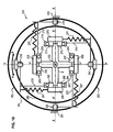
- FIGS. 1A and 1B schematically represent a mini-scale 100 according to a first embodiment of the invention.
- the mini-stick 100 comprises a frame 101 intended for example to be integrated into an armrest of a seat, a handle 102 mounted to rotate relative to the frame, and a mechanical assembly 103 connecting the handle to the frame for generating a return of force on the handle according to two axes of rotation.
- the handle 102 has a generally elongate shape in a longitudinal direction (Z 'axis). More specifically, the handle 102 comprises an elongated upper portion 112 intended to be grasped by the hand of the pilot, an elongated lower portion 122 adapted to cooperate with the mechanical linkage assembly 103, and an intermediate portion 132 having a spherical outer surface 142 .
- the frame 101 comprises a support portion having a spherical inner surface 111 receiving the intermediate portion 132 of the handle 102.
- the handle 102 is thus connected to the frame 101 by a ball joint 150 constituted by the spherical outer surface 142 of the intermediate portion 132 of the handle 102 and the spherical inner surface 111 complementary to the support portion of the frame 101.
- the mechanical linking assembly 103 comprises two pairs of connecting pieces, including a first pair of connecting pieces 113, 123 and a second pair of connecting pieces 133, 143.
- Each connecting piece 113, 123 of the first pair is mounted to rotate relative to the frame 101 about a first axis of rotation (X axis) through first pivot links 110 and 120.
- each connecting piece 133, 143 of the second pair is mounted to move relative to the frame 101 about a second axis of rotation (Y axis) through second pivot links 130 and 140.
- the second axis of rotation (Y axis) is perpendicular to the first axis of rotation (X axis ).
- the first axis of rotation and the second axis of rotation intersect at a point of intersection O which is also the center of rotation of the lever 102 relative to the frame 101, the center of the ball joint 150 (shown offset on the figure along the Z 'axis for the sole purpose of clearing the view of the parts in the drawing).
- the mechanical linking assembly 103 also comprises four sets of cradles 153, 163, 173 and 183, including two first sets of cradles 153, 163 and two second sets of cradles 173, 183.
- Each set of cradles includes a built-in cradle and a cradle controller.
- each first set of cradles 153, 163 the cradle 154, 164 is mounted integral with the first connecting pieces 113, 123, so that a rotation of the first connecting pieces 113, 123 around the first axis of rotation X leads to also a rotation of the first sets of cradles 153, 163.
- the cradle 155, 165 is rotatably mounted relative to the cradle 154, 164 according to a third axis of rotation (Y 'axis) perpendicular to the first axis of rotation (X axis).
- the cradle 174, 184 is mounted integral with the second connecting pieces 133, 143, so that a rotation of the second connecting pieces 133, 143 around the second axis of Rotation Y also causes a rotation of the second sets of cradles 173, 183.
- the cradle 175, 185 is rotatably mounted relative to the outer cradle 174, 184 along a fourth axis of rotation (X 'axis) perpendicular to the second axis of rotation (Y axis).
- the lever cradles 155, 165, 175 and 185 constitute intermediate parts of the mechanical linking assembly 103 for linking the connecting pieces to the lever 102.
- each first set of cradles 153, 163, the cradle 155, 165 is adapted to be rotated relative to the cradle 154, 164 (and therefore relative to the first connecting piece) under the action of the handle 102 around the third axis of rotation.
- a rotation of the handle 102 about the third axis (Y axis) concurrently causes a rotation of the second sets of cradles 173, 183 and the second connecting pieces 133, 143 around the second axis of rotation relative to the frame (Y axis). ).
- each second set of cradles 173, 183 the cradle 175, 185 is adapted to be rotated relative to the cradle 174, 184 (and therefore compared to the second connecting piece) under the action of the handle 102 around the fourth axis of rotation.
- a rotation of the handle 102 about the fourth axis (X 'axis) concurrently causes a rotation of the first sets of cradles 153, 163 and first connecting pieces 113, 123 around the first axis of rotation relative to the frame 101 (axis X).
- the minimium 100 comprises a connecting piece 113, a set of cradles including a fixed cradle 154 relative to the connecting piece 113 and a cradle 155 movable relative to the cradle fixed frame 154 (and therefore with respect to the piece link), and a return member 156 extending between a connecting piece 123 and the cradle mobile lever 155.
- the return member 156 is adapted to exert a return torque tending to oppose a rotation of the cradle lever 155 relative to the cradle frame 154, that is to say to oppose a rotation of the handle 102 relative to the frame 101.
- the return member 156 comprises a helical linear spring 157 and a ribbon 158 from wrapping around a cylindrical surface portion of the cradle 155.
- the ribbon 158 has a first end attached to the cylindrical surface portion and a second end attached to a second end of the spring.
- the spring 157 has a first end attached to the connecting piece and a second end attached to the second end of the ribbon.
- a rotation of the handle cradle 155 relative to the cradle 154 causes a winding of the tape 158 and an elongation of the spring 157, the elongation of the spring 157 being proportional to the rotation angle ⁇ of the cradle 155 relative to the cradle frame 154 around the Y 'axis.
- This arrangement makes it possible to obtain a linear force feedback on the handle 102.
- the cradle 155 lever is the outer cradle and the cradle 154 is the inner cradle of the set of 153. Therefore, the return member 156 exerts a return force on the outer lever cradle 155.
- the figures 3 , 4A and 4B are an example of mounting in which, in each set of cradles 173, 183, the cradle 175, 185 is the inner cradle and the cradle 174, 184 is the outer cradle.
- the return member 176, 186 exerts a return force on the internal lever cradle 175, 185.
- the lower portion 122 of the handle 102 comprises four protuberances 152, 162, 172 and 182.
- each cradle 155, 165, 175 and 185 handle has a stop.
- Each protuberance 152, 162, 172 and 182 is adapted to bear against a corresponding stop of a cradle lever 155, 165, 175 and 185 to rotate the cradle handle.
- the protuberances and the stops are arranged so that a rotation of the handle 102 along the fourth axis of rotation (axis X ') in a first direction causes a rotation of the handle cradle 175 relative to the cradle 174, without causing the cradle joystick 185 in rotation. Conversely, a rotation of the handle 102 along the fourth axis of rotation (axis X ') in a second direction, opposite to the first direction, causes a rotation of the cradle lever 185 relative to the cradle frame 184, without causing the cradle joystick 175 in rotation.
- each cradle 155, 165, 175, 185 is equipped with its own return member, it is possible to provide return members 156, 166, 176, 186 having different characteristics, in order to obtain a force feedback. different in the direction of stress on the handle around the axis X 'and the axis Y'.
- the proposed assembly makes it possible to work the return members 156, 166, 176, 186 only in tension, so that no device for guiding the return members is necessary and that any risk of buckling of the elements constituting these return members, whether the ribbon 158 or the helical linear spring 157, is eliminated.
- this arrangement makes it possible to design a mini-stick 100 in which the return members 156, 166, 176, 186 are mounted by being pretensioned in tension, that is to say that each return member 156, 166, 176, 186 exerts a non-zero return force on the handle 102 when the handle 102 is in the neutral position. This makes it possible to create a threshold of effort to be overcome during the initialization of the displacement of the joystick.
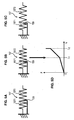
- FIGS. 5A to 5C schematically represent an example of a return member 156 for generating a double stiffness in a direction of rotation.
- the return member 156 comprises a spring 157 and a stopper 159.
- the spring 157 has a first spring portion 1571 and a second spring portion 1572 connected in series with the first spring portion 1572, the stopper 159 being interposed between a turn of the first spring portion 1571 and a turn of the second spring portion 1572.
- the Figures 5B and 5C represent the spring 157 when the lever 102 is biased by the pilot around the axis of rotation Y '.
- the spring 157 has been stretched by a first length Li.
- the two spring portions 1571 and 1572 have elongated until a turn of the first spring portion 1571 comes into play. against the stop 159. Once the turn of the first spring portion 1571 abuts against the stop 159, the first spring portion 1571 can no longer be elongated.
- the spring has been stretched by a second length L 2 , greater than the first length L 1 , but only the second spring portion 1572 has elongated, the first spring portion 1571 being neutralized by the stop 159.
- the figure 5D illustrates the intensity of the return force F generated by the return member 156 as a function of the elongation L of the spring 157. It can be seen that the force F generated follows a double slope force law. During the first phase, the two portions of spring are biased, so that the force generated has a linear variation having a first slope. During the second phase, only the second spring portion is biased, so that the force has a linear variation having a second slope; greater than the first slope.
- the ball joint 150 connecting the lever 102 to the frame 101 can be replaced by a universal joint 20.
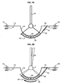
- the Figures 6A to 6C show schematically an example of gimbal system 21 that can be used to mount the handle 102 on the housing 101 of the mini 100. The system shown reduces the friction forces and eliminate any risk of seizure.
- the generally planar shape of the cardan system 21 shown frees space above the center of rotation 132 of the handle 102, which is particularly advantageous in a confined environment.
- the cardan system 21 shown on the Figures 6A to 6C comprises a flat base 22, a flat intermediate piece 23, and two support pieces 24 and 25.
- the flat base 22 is fixed to the frame 101 of the mini-board 100 and the handle 102 is fixed to the two support pieces 24 and 25:
- the cardan system 21 further comprises two flexible blades 26, 27 linking the base 22 to the intermediate part 23 and allowing a rotation of the intermediate part 23 relative to the base 22 plane according to a first axis of rotation (x axis).
- the cardan system 21 also comprises two flexible blades 28, 29 linking the intermediate piece 23 to the support pieces 24, 25 and allowing a rotation of the support pieces 24, 25 with respect to the intermediate piece 23 along a second axis of rotation ( y axis) perpendicular to the first axis of rotation.
- the handle 102 can be rotated relative to the housing according to the two axes of rotation x and y, these two axes of rotation being fixed relative to the frame 101.
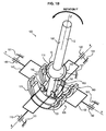
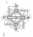
- FIGS. 7A to 7C schematically represent a mini-stick 200 according to a second embodiment of the invention.
- the sets of cradles 153, 163, 173 and 183 have been replaced by ball bearings 253, 263, 273, 283, each bearing comprising a handle ring 255, 265, 275, 285 and a ring built 254, 264, 274, 284.
- the minimium 200 comprises a frame 201, a handle 202 mounted to rotate with respect to the frame, and a mechanical assembly 203 for connecting the handle to the frame.
- the mechanical linking assembly 203 comprises two pairs of connecting pieces, including a first pair of connecting pieces 213, 223 and a second pair of connecting pieces 233, 243.
- Each connecting piece 213, 223 of the first pair is mounted to rotate relative to the frame 201 about a first axis of rotation (X axis) through first pivot links 210 and 220.
- each connecting piece 233, 243 of the second pair is mounted movably relative to the frame 201 about a second axis of rotation (Y axis) through second pivot links 230 and 240.
- the mechanical linkage assembly 203 also comprises four bearings 253, 263, 273 and 283, including a first pair of bearings 253, 263 and a second pair of bearings 273, 283.
- Each bearing comprises a handle ring and a housing ring.
- the housing ring 254, 264 is mounted integral with the first connecting pieces 213, 223, so that a rotation of the first connecting pieces 213, 223 around the first axis of rotation X leads to also a rotation of the bearings 253, 263.
- the handle ring 255, 265 is rotatably mounted relative to the housing ring 254, 264 according to a third axis of rotation (Y 'axis) perpendicular to the first axis of rotation ( X axis).
- the ring 274, 284 is mounted integral with the second connecting pieces 233, 243, so that a rotation of the second connecting pieces 233, 243 around the second axis of rotation Y also causes rotation of the bearings 273, 283.
- the handle ring 275, 285 is rotatably mounted relative to the frame ring 274, 284 along a fourth axis of rotation (axis X ') perpendicular to the second axis rotation (Y axis).
- lever rings 255, 265, 275 and 285 constitute intermediate parts of the mechanical linkage assembly 203 for linking the connecting pieces to the lever 202.
- the minimium 200 comprises a return member 256 extending between a connecting piece 223 and the handle ring 255, as in the first embodiment.
- the return member 256 is able to exert a return torque tending to oppose a rotation of the handle ring 255 relative to the ring 254, that is to say to oppose a rotation of the handle 202 relative to the frame 201.
- the return member 256 comprises a helical linear spring 257 and a ribbon 258 wound around a cylindrical surface portion 259 of the handle ring 255.
- the figure 8A illustrates the return member 256 when the joystick 202 is in the neutral position.
- the Figure 8B illustrates the return member 256 when the handle 202 is rotated about the axis Y 'in a first direction of rotation.
- the lever ring 255 rotated by the handle 202, does not cause the ribbon 258, which does not wrap around the cylinder portion of the handle ring 255, leaving unchanged the elongation of the spring 257.
- the Figure 8C illustrates the return member 256 when the handle 202 is rotated about the axis Y 'in a second direction of rotation, opposite to the first direction of rotation.
- the handle 202 rotates the handle ring 255, which has the effect of winding the tape 258 around the handle ring 255.
- the tape 258 exerts a pull on the spring 257 which elongates and generates a return force tending to oppose the rotation of the handle ring 255 with respect to the frame ring 254.
- each cradle handles 175 and 185 has a stop.
- the lower part 122 of the handle 102 is able to bear against a stop of a cradle 175 and handle 185 to rotate the cradle lever.
- the stops are arranged so that a rotation of the handle 102 along the fourth axis of rotation (axis X ') in a first direction causes a rotation of the cradle 175 relative to the cradle 174, without driving the cradle 185 lever rotation. Conversely, a rotation of the handle 102 along the fourth axis of rotation (axis X ') in a second direction, opposite to the first direction, causes a rotation of the cradle lever 185 relative to the cradle frame 184, without causing the cradle joystick 175 in rotation.
- the handle 102 is in contact with the stops in a rectilinear line of contact.
- the handle 202 is in contact with the stops along a cylindrical contact surface.
- the contact between the lever 102 and the stops allows a rotation of the lever 102 relative to the cradles 175 and lever 185 around the Z 'axis without causing any parasitic rotation of the cradles 175 and 185 relative to the cradles frame 174 and 184, which is essential not to generate coupling between the axes X 'and Y'.
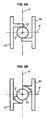
- the figure 10 schematically represents a first variant of the Figures 7A to 7C .
- the pivots 220 and 210 are fixedly mounted on the frame 201, while the pivots 230 and 240 are rotatably mounted relative to the frame 201.
- the second connecting pieces 233 and 243 are rotatably mounted compared to the frame 201 around a fifth axis (Z axis), the fifth axis being perpendicular to the first axis (X axis) and the second axis (Y axis) and passing through the center of rotation O of the joystick 202.
- the mechanical linkage unit 203 comprises a fifth bearing 293 comprising an outer ring 294 fixedly mounted relative to the frame 201 and an inner ring 295 rotatably mounted relative to the outer ring 294 (and therefore with respect to the frame 201) about the Z axis.
- the connecting pieces 233 and 243 are rotatably mounted on the inner ring 295 about the Y axis through pivots 230 and 240.
- This arrangement allows a rotation of one of the fixed reference systems (Y defined by the connecting pieces 233 and 243) relative to the other fixed reference (X defined by the connecting pieces 213 and 223) around the Z axis , while the two axes X 'and Y' of the pivotal reference remain fixed and orthogonal with respect to each other.
- This arrangement allows a variation of the angle formed between the first axis of rotation X and the second axis of rotation Y, the first axis of rotation X being fixed relative to the frame 201.
- the figure 11 schematically represents a second variant of the Figures 7A to 7C wherein the first axis of rotation X and the second axis of rotation Y are movable relative to the frame 201.
- the mechanical linkage assembly 203 comprises a fifth bearing 293 comprising an outer ring 294 and an inner ring 295, each of the rings 294 and 295 being rotatably mounted relative to the frame 201 about the Z axis.
- the mechanical linkage assembly 203 also comprises a plurality of rollers 296 interposed between the rings 294 and 295 and rotatably mounted by relative to the frame 201 about their axis, which are parallel to the Z axis and fixed relative to the frame 201.
- the rollers 296 make it possible to rotate the rings 294 and 295 in rotation so that a rotation of one of the rings relative to the frame 201 in one direction causes concomitantly a rotation of the other ring in the opposite direction of an identical angle. .
- This arrangement also allows a rotation of the fixed reference systems X and Y relative to each other (defined on the one hand by the connecting pieces 213 and 223 and on the other hand by the connecting pieces 233 and 243) around of the Z axis, while the two axes X 'and Y' of the pivotal reference remain fixed and orthogonal with respect to each other.
- This assembly thanks to this additional degree of freedom made indispensable by projection of the vectors rotations, also allows a displacement of the joystick 202 in rotation simultaneously along the first axis of rotation X and the second axis of rotation Y, and this without inducing rotation of the handle along the axis Z '.
- the figure 12 schematically represents a third variant of the Figures 7A to 7C wherein the bearings are rotatable.
- the bearings 253 and 263 are fixedly mounted relative to the handle 202, while the bearings 273 and 283 are rotatably mounted relative to the handle 202.
- the intermediate parts 275 and 285 (formed by the bearing bushes 273 and 283) are rotatably mounted relative to the handle 202.
- the fifth axis being perpendicular to the third axis (Y' axis) and the fourth axis ( X ') and passing through the center of rotation O of the joystick 202.
- the mechanical connection unit 203 comprises a fifth bearing 293 comprising an inner ring 295 fixed mounted relative to the handle 202 and an outer ring 294 mounted movable relative to the inner ring 295 (and therefore relative to the handle 202) about the axis Z '.
- the intermediate parts 275 and 285 are fixedly mounted on the outer ring 294 of the fifth bearing 293.
- This arrangement allows a rotation of the handle 202 relative to one of the pivotal references (defined by the connecting pieces 233 and 243) about the axis Z '(longitudinal axis of the handle 202).
- This arrangement allows a variation of the angle formed between the third axis of rotation Y 'and the fourth axis of rotation X', the third axis of rotation Y 'being fixed relative to the handle 202.
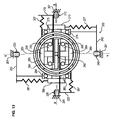
- the figure 13 schematically represents a fourth variant of the Figures 7A to 7C .
- This fourth variant has a functioning identical to that of the third variant. While the third variant allows the use of identical bearings 253, 263, 273 and 283, the fourth variant is more compact by including nested bearings.
- the outer ring 294 of the fifth bearing 293 is fixed to the internal lever rings 275 and 285 of the bearings 273 and 283 of the second pair.
- the inner ring 295 of the fifth bearing 293 is attached to the outer handle rings 255 and 265 of the bearings 253 and 263 of the first pair.
- the figure 14 schematically represents a fifth variant of the Figures 7A to 7C , wherein the fourth axis of rotation X 'and the third axis of rotation Y' are movable relative to the handle 202.
- the mechanical linkage assembly 203 comprises a fifth bearing 293 comprising an outer ring 294 and an inner ring 295, each of the rings 294 and 295 being rotatably mounted relative to the handle 202 about the axis Z '.
- the mechanical connection unit 203 also comprises a plurality of rollers 296 interposed between the rings 294 and 295 and rotatably mounted relative to the lever about their axes, which are parallel to the axis Z 'and fixed relative to the joystick 202.
- the rollers 296 make it possible to link the rings 294 and 295 in rotation so that a rotation of one of the rings relative to the lever 202 in one direction simultaneously causes a rotation of the other ring in the opposite direction of an angle. identical.
- This arrangement allows a rotation of the handle 202 with respect to each of the pivotal reference frames (the pivotal references being respectively defined by the connecting pieces 213 and 223 and by the connecting pieces 233 and 243) about the axis Z '.
- This assembly thanks to this additional degree of freedom made indispensable by projection of the vectors rotations, also allows a displacement of the joystick 202 in rotation simultaneously along the first axis of rotation X and the second axis of rotation Y, and this without inducing rotation of the handle along the axis Z '.
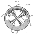
- the figure 15 schematically shows a connecting member 393 that can be used in the variant of the figure 14 instead of the fifth bearing 293 and the plurality of associated rollers 296.
- the link member 393 shown comprises a first portion 394, a second portion 395 and a third portion 396.
- the first portion 394 is movably mounted relative to the third portion 396.
- the second portion 395 is mounted movably relative to in the third part 396.
- the connecting member 393 also comprises two pairs of flexible blades 301 and 302, 303 and 304.
- Each flexible blade 301, 302 of first pair connects the first portion 394 and the third portion 396 between them and is elastically deformable to allow rotation of the third portion 396 relative to the first portion 394.
- the flexible blades 301 and 302 are adapted to generate a return torque tending to oppose the rotation of the parts 394 and 396 between them.
- each flexible blade 303, 304 of the second pair connects the second portion 395 and the third portion 396 between them and is elastically deformable to allow rotation of the third portion 396 relative to the second portion 395.
- the flexible blades 303, 304 are able to generate a return torque tending to oppose the rotation of the parts 395 and 396 between them.
- the first portion 394 is attached to the intermediate pieces 275 and 285.
- the second part 395 is attached to the intermediate parts 255 and 265.
- the third portion 396 is attached to the joystick 202.
- this assembly allows a rotation of the handle 202 relative to each of the pivotal reference frames (the pivotal references being defined respectively by the connecting pieces 213 and 223 and the connecting pieces 233 and 243) about the axis Z '.
- This assembly thanks to this additional degree of freedom made indispensable by projection of the vectors rotations, also allows a displacement of the joystick 202 in rotation simultaneously along the first axis of rotation X and the second axis of rotation Y, and this without inducing rotation of the handle along the axis Z '.
Landscapes
- Engineering & Computer Science (AREA)
- Automation & Control Theory (AREA)
- Aviation & Aerospace Engineering (AREA)
- Physics & Mathematics (AREA)
- General Physics & Mathematics (AREA)
- Mechanical Control Devices (AREA)
- Position Input By Displaying (AREA)
Claims (19)
- Sidestick (100, 200) zur Steuerung eines Luftfahrzeugs, der ein Gehäuse (101, 201), einen Griff (102, 202), der in Bezug zu dem Gehäuse drehbeweglich gelagert ist, und eine mechanische Baugruppe zur Verbindung (103, 203) des Griffs mit dem Gehäuse umfasst, wobei die mechanische Verbindungsbaugruppe (103, 203) Folgendes umfasst:- ein erstes Verbindungsteil (113, 123, 213, 223), das in Bezug zum Gehäuse (101, 201) um eine erste Drehachse (X) herum beweglich gelagert ist, und- ein zweites Verbindungsteil (133, 143, 233, 243), das in Bezug zu dem Gehäuse (101, 201) um eine zweite Drehachse (Y) herum beweglich gelagert ist, wobei die zweite Drehachse einen Winkel von nicht Null mit der ersten Drehachse bildet, dadurch gekennzeichnet, dass die mechanische Baugruppe zur Verbindung ferner umfasst:- ein drittes, dazwischenliegendes Teil (155, 165, 255, 265), das in Bezug zum ersten Verbindungsteil (113, 123, 213, 223) um eine dritte Drehachse (Y') herum drehbeweglich gelagert ist, und- ein viertes, dazwischenliegendes Teil (175, 185, 275, 285), das in Bezug zu dem zweiten Verbindungsteil (133, 143, 233, 243) um eine vierte Drehachse (X') herum drehbeweglich gelagert ist, wobei die vierte Drehachse einen Winkel von nicht Null mit der dritten Drehachse bildet,und dass die Verbindungsteile (113, 123, 213, 223 ; 133, 143, 233, 243) oder die dazwischenliegenden Teile (155, 165, 255, 265 ; 175, 185, 275, 285) in Bezug zueinander um eine fünfte Drehachse (Z, Z') herum drehbeweglich sind, die einen Winkel von nicht Null mit der ersten Drehachse (X) und der zweiten Drehachse (Y) beziehungsweise mit der dritten Drehachse (X') und der vierten Drehachse (Y') bildet, derart, dass eine Veränderung des Winkels, der zwischen der ersten Drehachse und der zweiten Drehachse gebildet wird, oder des Winkels, der zwischen der dritten Drehachse und der vierten Drehachse gebildet wird, zugelassen wird.
- Sidestick nach Anspruch 1, wobei die mechanische Verbindungsbaugruppe (203) ein Verbindungsorgan (293) umfasst, das einen äußeren Ring (294) und einen inneren Ring (295) umfasst, die in Bezug zueinander um die fünfte Drehachse (Z, Z') herum drehbar gelagert sind, wobei jedes der Verbindungsteile (213, 223 ; 233, 243) beziehungsweise der dazwischenliegenden Teile (255, 265 ; 275, 285) mit einem entsprechenden Ring (294, 295) des Verbindungsorgans (293) verbunden ist, wobei der Griff (102, 202) fest mit dem dritten dazwischenliegenden Teil (255, 265) und/oder dem vierten dazwischenliegenden Teil (275, 285) verbunden ist.
- Sidestick nach Anspruch 2, wobei einer der Ringe (294) des Verbindungsorgans (293) in Bezug zum ersten Verbindungsteil (213, 223) fest ist und der andere Ring (295) in Bezug zum zweiten Verbindungsteil (233, 243) fest ist.
- Sidestick nach Anspruch 3, wobei einer von den Ringen (294 oder 295) des Verbindungsorgans (293) in Bezug zum Gehäuse (201) fest ist, derart, dass eine Drehung einzig des ersten Verbindungsteils (213, 223) oder einzig des zweiten Verbindungsteils (233, 243) in Bezug zum Gehäuse (201) um die fünfte Drehachse (Z) herum zugelassen wird.
- Sidestick nach Anspruch 3, wobei das Verbindungsorgan (293) mindestens eine Rolle (296) umfasst, die um eine Drehachse herum drehbar ist, die in Bezug zum Gehäuse (201) fest ist, wobei die Rolle (296) derart zwischen dem inneren Ring (295) und dem äußeren Ring (294) angeordnet ist, dass eine Drehung von einem der Ringe in Bezug zu dem Gehäuse (201) begleitend eine Drehung des anderen Rings in die entgegengesetzte Richtung in Bezug zu dem Gehäuse (201) mit sich bringt.
- Sidestick nach Anspruch 2, wobei einer der Ringe (295) des Verbindungsorgans (293) in Bezug zum dritten dazwischenliegenden Teil (255, 265) fest ist und der andere Ring (294) in Bezug zum vierten dazwischenliegenden Teil (275, 285) fest ist.
- Sidestick nach Anspruch 6, wobei einer von den Ringen (294 oder 295) des Verbindungsorgans (293) in Bezug zum Griff (202) fest ist, derart, dass eine Drehung des Griffs (202) einzig in Bezug zum dritten dazwischenliegenden Teil (255, 265) oder einzig in Bezug zum vierten dazwischenliegenden Teil (275, 285) um die fünfte Drehachse (Z') herum zugelassen wird.
- Sidestick nach Anspruch 6, wobei das Verbindungsorgan (293) mindestens eine Rolle (296) umfasst, die um eine Drehachse herum drehbar gelagert ist, die in Bezug zum Griff (202) fest ist, wobei die Rolle (296) derart zwischen dem inneren Ring (295) und dem äußeren Ring (294) angeordnet ist, dass eine Drehung von einem der Ringe (294, 295) in Bezug zu dem Griff (202) begleitend eine Drehung des anderen Rings (294, 295) in die entgegengesetzte Richtung in Bezug zu dem Griff (202) mit sich bringt.
- Sidestick nach Anspruch 1, wobei die mechanische Verbindungsbaugruppe (203) ein Verbindungsorgan (393) umfasst, das einen festen Teil (396) und einen Teil (394, 395) umfasst, der in Bezug zum festen Teil beweglich gelagert ist, wobei das Verbindungsorgan (393) mindestens zwei biegsame Blätter (301, 302 ; 303, 304) umfasst, wobei jedes biegsame Blatt (301, 302 ; 303, 304) die Teile (394, 395, 396) untereinander verbindet und elastisch verformbar ist, um eine Drehung des beweglichen Teils (394, 395) in Bezug zum festen Teil (396) zuzulassen, wobei die beweglichen Blätter (301, 302 ; 303, 304) geeignet sind, ein Rückstellmoment zu erzeugen, das dazu neigt, der Drehung der Teile (394, 395, 396) untereinander entgegen zu wirken.
- Sidestick nach Anspruch 9, wobei das dritte dazwischenliegende Teil (255, 265) oder das vierte dazwischenliegende Teil (275, 285) an einem Teil (394, 395) des Verbindungsorgans (393) befestigt ist und der Griff (202) an dem anderen Teil (396) des Verbindungsorgans (393) befestigt ist.
- Sidestick nach einem der vorhergehenden Ansprüche, wobei der Griff (102, 202) mit dem Gehäuse (101, 201) durch eine Kugelgelenkverbindung (150) verbunden ist, die eine Drehung des Griffs (102, 202) entlang den drei Drehachsen (X, Y, Z ; Z') in Bezug zum Gehäuse (101, 201) zulässt.
- Sidestick nach Anspruch 1, wobei der Griff (102, 202) mit dem Gehäuse (101, 201) durch eine Kardangelenkverbindung verbunden ist, die einzig eine Drehung des Griffs (102, 202) entlang der ersten Achse (X) und eine Drehung des Griffs (102, 202) entlang der zweiten Achse (Y) in Bezug zum Gehäuse (101, 201) zulässt.
- Sidestick nach Anspruch 12, wobei der Griff (102, 202) geeignet ist, in einfache Auflage auf dem dritten dazwischenliegenden Teil und auf dem vierten dazwischenliegenden Teil zu kommen, um die dazwischenliegenden Teile entlang der dritten beziehungsweise der vierten Achse (Y', X') drehbar zu beanspruchen, derart, dass eine relative Drehung der dazwischenliegenden Teile in Bezug zum Griff (102, 202) entlang der fünften Drehachse (Z, Z') zugelassen wird.
- Sidestick nach Anspruch 13, wobei eines der dazwischenliegenden Teile einen Anschlag umfasst, der derart angeordnet ist, dass der Griff (202) geeignet ist, auf dem Anschlag in Auflage zu kommen, um das dazwischenliegende Teil zu beanspruchen und die Drehung des dazwischenliegenden Teils in eine einzige Beanspruchungsrichtung zu bewirken.
- Sidestick nach Anspruch 14, wobei der Griff (202) geeignet ist, auf dem Anschlag entlang einer geradlinigen Berührungslinie in Auflage zu kommen, die parallel zur fünften Drehachse (Z, Z') ist.
- Sidestick nach Anspruch 14, wobei der Griff (202) geeignet ist, auf dem Anschlag entlang einer zylindrischen Berührungslinie in Auflage zu kommen, die eine Rotationsachse aufweist, die parallel zur fünften Drehachse (Z, Z') ist.
- Sidestick nach einem der vorhergehenden Ansprüche, der ein Rückstellorgan (156, 166, 176, 186, 256, 266, 276, 286) umfasst, das geeignet ist, eines der dazwischenliegenden Teile (155, 165, 175, 185, 255, 265, 275, 285) des Verbindungsorgans (253, 263, 273, 283) zu beanspruchen, um der Drehung des dazwischenliegenden Teils entgegen zu wirken.
- Sidestick nach Anspruch 17, wobei das Rückstellorgan (156, 166, 176, 186, 256, 266, 276, 286) eine Zugfeder (157, 167, 177, 187, 257, 267, 277, 287) umfasst, die das erste Verbindungsteil (113, 123, 213, 223) oder das zweite Verbindungsteil (133, 143, 233, 243) mit dem dazwischenliegenden Teil (155, 165, 175, 185, 255, 265, 275, 285) verbindet, das unter der Einwirkung des Griffs (202) drehbar mitgenommen wird.
- Sidestick nach Anspruch 18, wobei das Rückstellorgan (156, 166, 176, 186, 256, 266, 276, 286) ein Band (158, 258) umfasst, das die Zugfeder (157, 167, 177, 187, 257, 267, 277, 287) und das dazwischenliegende Teil (155, 165, 175, 185, 255, 265, 275, 285) verbindet, wobei das Band geeignet ist, sich um ein zylindrisches Element (259, 269, 279, 289) herum zu wickeln, und fest mit dem dazwischenliegenden Teil (155, 165, 175, 185, 255, 265, 275, 285) verbunden ist.
Applications Claiming Priority (2)
| Application Number | Priority Date | Filing Date | Title |
|---|---|---|---|
| FR1255322A FR2991662B1 (fr) | 2012-06-07 | 2012-06-07 | Minimanche de pilotage d'un aeronef |
| PCT/EP2013/061792 WO2013182679A1 (fr) | 2012-06-07 | 2013-06-07 | Minimanche de pilotage d'un aeronef |
Publications (2)
| Publication Number | Publication Date |
|---|---|
| EP2858897A1 EP2858897A1 (de) | 2015-04-15 |
| EP2858897B1 true EP2858897B1 (de) | 2016-04-27 |
Family
ID=46785631
Family Applications (1)
| Application Number | Title | Priority Date | Filing Date |
|---|---|---|---|
| EP13729007.8A Active EP2858897B1 (de) | 2012-06-07 | 2013-06-07 | Joystick zum steuern eines flugzeugs |
Country Status (9)
| Country | Link |
|---|---|
| US (1) | US9242722B2 (de) |
| EP (1) | EP2858897B1 (de) |
| CN (1) | CN104520183B (de) |
| BR (1) | BR112014030398A2 (de) |
| CA (1) | CA2875929A1 (de) |
| FR (1) | FR2991662B1 (de) |
| IN (1) | IN2014DN10364A (de) |
| RU (1) | RU2611323C2 (de) |
| WO (1) | WO2013182679A1 (de) |
Families Citing this family (15)
| Publication number | Priority date | Publication date | Assignee | Title |
|---|---|---|---|---|
| FR2991663B1 (fr) * | 2012-06-07 | 2014-06-13 | Sagem Defense Securite | Minimanche de pilotage d'un aeronef |
| US10004348B2 (en) | 2014-01-19 | 2018-06-26 | Runway Blue, Llc | Lid for a container |
| FR3042775B1 (fr) * | 2015-10-21 | 2017-11-10 | Sagem Defense Securite | Dispositif de commande de vol d'un aeronef |
| CN105947186B (zh) * | 2016-05-31 | 2018-08-24 | 中国航空工业集团公司西安飞机设计研究所 | 一种中性速度稳定性补偿控制方法 |
| US10098778B1 (en) * | 2016-06-20 | 2018-10-16 | Boston Incubator Center, LLC | Compliant body support system for crouching and kneeling work |
| JP6731302B2 (ja) * | 2016-07-21 | 2020-07-29 | 川崎重工業株式会社 | 操作装置 |
| RU2652284C1 (ru) * | 2016-12-27 | 2018-04-25 | Федеральное государственное бюджетное образовательное учреждение высшего образования "Чувашский государственный университет имени И.Н. Ульянова" | Устройство ручного управления летательным аппаратом |
| US10272327B2 (en) * | 2017-07-13 | 2019-04-30 | Performance Designed Products Llc | Detachable joystick for video game controller |
| US10183218B1 (en) | 2017-07-13 | 2019-01-22 | Performance Designed Products Llc | Detachable joystick for video game controller |
| USD890846S1 (en) | 2017-08-07 | 2020-07-21 | Performance Designed Products Llc | Video game controller |
| CN109460048B (zh) * | 2018-11-02 | 2021-10-15 | 中国航空工业集团公司西安飞机设计研究所 | 一种轨迹不稳定性控制方法 |
| RU2724939C1 (ru) * | 2019-12-18 | 2020-06-26 | Федеральное государственное бюджетное образовательное учреждение высшего образования "Поволжский государственный технологический университет" | Устройство для обучения управлению подвижными объектами с помощью джойстиков |
| FR3117623A1 (fr) * | 2020-12-15 | 2022-06-17 | Dassault Aviation | Dispositif de pilotage d'un aéronef et procédé associé |
| WO2022216939A1 (en) * | 2021-04-08 | 2022-10-13 | SkyRyse, Inc. | Four-axis mechanical controller |
| USD1034816S1 (en) | 2022-03-07 | 2024-07-09 | Performance Designed Products Llc | Video game controller |
Family Cites Families (20)
| Publication number | Priority date | Publication date | Assignee | Title |
|---|---|---|---|---|
| US1415176A (en) * | 1921-06-04 | 1922-05-09 | John T Hughes | Aeroplane control |
| US3394611A (en) * | 1966-04-25 | 1968-07-30 | Bell Telephone Labor Inc | Output control device with adjustable self-returning null |
| US3757597A (en) * | 1972-10-20 | 1973-09-11 | France Etat | Aiming device |
| DE2842842A1 (de) * | 1978-10-02 | 1980-05-29 | Brand Elektronik Gmbh | Steuereinrichtung, insbesondere fernsteuereinrichtung fuer flugmodelle |
| US4587510A (en) * | 1983-10-19 | 1986-05-06 | Wico Corporation | Analog joystick controller |
| DE3825809A1 (de) * | 1988-07-29 | 1990-02-08 | Messerschmitt Boelkow Blohm | Steuereinrichtung mit einem steuerknueppel |
| JPH0434610A (ja) * | 1990-05-31 | 1992-02-05 | Fuji Heavy Ind Ltd | ジンバル装置 |
| RU2018458C1 (ru) * | 1991-04-19 | 1994-08-30 | Московский научно-производственный комплекс "Авионика" | Боковая рукоятка управления |
| JPH07111664B2 (ja) * | 1992-03-18 | 1995-11-29 | 川崎重工業株式会社 | 航空機用ジョイスティックタイプコントローラのフィール機構 |
| US6437771B1 (en) * | 1995-01-18 | 2002-08-20 | Immersion Corporation | Force feedback device including flexure member between actuator and user object |
| WO1997017651A1 (fr) * | 1995-11-10 | 1997-05-15 | Nintendo Co., Ltd. | Systeme de manche a balai |
| US6128971A (en) * | 1998-12-21 | 2000-10-10 | Caterpillar Inc. | Control device |
| JP2001020907A (ja) * | 1999-05-06 | 2001-01-23 | Komatsu Ltd | 操作レバー装置 |
| US6647820B2 (en) * | 2001-09-17 | 2003-11-18 | Lockheed Martin Corporation | Variable position hand control mount for operator controls |
| SE524018C2 (sv) * | 2002-10-03 | 2004-06-15 | Parker Hannifin Ab | Manöveranordning samt metod för manövrering av ett manöverobjekt |
| GB2437746A (en) * | 2006-05-05 | 2007-11-07 | Cnh Uk Ltd | Remotely configurable control lever |
| US8033197B2 (en) * | 2006-11-20 | 2011-10-11 | Honeywell International Inc. | Fully floating, self-aligning, self-adjusting gimbal assembly for an active human machine interface |
| DE102008034444B4 (de) * | 2008-05-14 | 2013-09-05 | Diehl Aerospace Gmbh | Eingabesystem für eine Landeklappensteuerung eines Flugzeugs |
| US8770055B2 (en) * | 2010-06-11 | 2014-07-08 | Mason Electric Company | Multi-axis pivot assembly for control sticks and associated systems and methods |
| CN102141468B (zh) * | 2010-12-20 | 2013-05-01 | 中国商用飞机有限责任公司 | 一种二自由度操纵杆驱动试验装置及其控制方法 |
-
2012
- 2012-06-07 FR FR1255322A patent/FR2991662B1/fr active Active
-
2013
- 2013-06-07 US US14/405,758 patent/US9242722B2/en active Active
- 2013-06-07 BR BR112014030398A patent/BR112014030398A2/pt not_active IP Right Cessation
- 2013-06-07 IN IN10364DEN2014 patent/IN2014DN10364A/en unknown
- 2013-06-07 RU RU2014150489A patent/RU2611323C2/ru active
- 2013-06-07 EP EP13729007.8A patent/EP2858897B1/de active Active
- 2013-06-07 CN CN201380034136.8A patent/CN104520183B/zh active Active
- 2013-06-07 CA CA2875929A patent/CA2875929A1/fr not_active Abandoned
- 2013-06-07 WO PCT/EP2013/061792 patent/WO2013182679A1/fr active Application Filing
Non-Patent Citations (1)
| Title |
|---|
| None * |
Also Published As
| Publication number | Publication date |
|---|---|
| US20150158575A1 (en) | 2015-06-11 |
| RU2014150489A (ru) | 2016-07-27 |
| CN104520183A (zh) | 2015-04-15 |
| CA2875929A1 (fr) | 2013-12-12 |
| FR2991662B1 (fr) | 2014-06-13 |
| EP2858897A1 (de) | 2015-04-15 |
| FR2991662A1 (fr) | 2013-12-13 |
| IN2014DN10364A (de) | 2015-08-07 |
| RU2611323C2 (ru) | 2017-02-21 |
| US9242722B2 (en) | 2016-01-26 |
| WO2013182679A1 (fr) | 2013-12-12 |
| BR112014030398A2 (pt) | 2017-06-27 |
| CN104520183B (zh) | 2016-04-13 |
Similar Documents
| Publication | Publication Date | Title |
|---|---|---|
| EP2858897B1 (de) | Joystick zum steuern eines flugzeugs | |
| FR2988689A1 (fr) | Dispositif de pilotage d'un vehicule, notamment d'aeronef | |
| WO2015107208A2 (fr) | Actionneur de commande d'un plan horizontal de stabilisation d'un aeronef | |
| EP2965989A1 (de) | Schnellbefestigungssystem eines zubehörteils am körper einer drohne | |
| WO2014161796A1 (fr) | Verin a cable permettant un debattement articulaire augmente | |
| EP2858896B1 (de) | Joystick zum steuern eines flugzeugs | |
| FR3013680A3 (fr) | Train d'atterrissage pour un avion leger ou un aeronef sans equipage et aeronef equipe d'un tel train d'atterrissage | |
| CA3124781C (fr) | Dispositif d'application d'effort pour un manche de pilotage d'un aeronef | |
| EP2500265A1 (de) | Zyklischer Steuerknüppel mit mechanischer Übersetzung zum Steuern eines Drehflügelflugzeugs, der einen selektiv erweiterten Hebelarm für den Notfall umfasst | |
| CA2977277A1 (fr) | Atterrisseur d'aeronef equipe d'un dispositif d'attenuation de shimmy | |
| EP1201537B1 (de) | Gestängeanordnung für Steuerflächen eines Flugzeuges | |
| EP2327604B1 (de) | Einstellvorrichtung für eine Lenksäule | |
| FR3048954A1 (fr) | Systeme de desengagement verrouillable d’actionneur de roue sur un atterisseur d’aeronef. | |
| EP3676062B1 (de) | Mechanische vorrichtung mit passiver nachgiebigkeit zur übertragung einer drehbewegung | |
| EP3203299B1 (de) | Verformbarer spiegel | |
| EP3365225B1 (de) | Flugsteuerungsvorrichtung für ein flugzeug | |
| EP1820079A1 (de) | Haptische schnittstelle mit kabeln | |
| EP3857329B1 (de) | Vorrichtung zur steuerung des flugs eines flugzeugs | |
| EP3847096B1 (de) | Flugsteuervorrichtung für ein flugzeug | |
| EP3467612B1 (de) | Vorrichtung zur erzeugung einer kraftempfindung durch reibung für ein flugsteuerungssystem eines luftfahrzeugs | |
| EP2905512B1 (de) | Steuervorrichtung eines Getriebes für Kraftfahrzeug | |
| FR2872128A1 (fr) | Dispositif de restitution artificielle d'effort antagoniste pour un dispositif de commande a distance de gouvernes d'un aeronef | |
| EP3156271A1 (de) | Stabilisator mit über eine verschiebbare manschette gekoppelten armen für eine kraftfahrzeugachse | |
| EP2136104B1 (de) | Vorrichtung zum Übertragen einer Drehbewegung und eine solche Vorrichtung umfassender Übertragungsmechanismus | |
| WO2013087790A1 (fr) | Ensemble mecanique articule et main mecanique comportant un tel ensemble |
Legal Events
| Date | Code | Title | Description |
|---|---|---|---|
| PUAI | Public reference made under article 153(3) epc to a published international application that has entered the european phase |
Free format text: ORIGINAL CODE: 0009012 |
|
| 17P | Request for examination filed |
Effective date: 20150106 |
|
| AK | Designated contracting states |
Kind code of ref document: A1 Designated state(s): AL AT BE BG CH CY CZ DE DK EE ES FI FR GB GR HR HU IE IS IT LI LT LU LV MC MK MT NL NO PL PT RO RS SE SI SK SM TR |
|
| AX | Request for extension of the european patent |
Extension state: BA ME |
|
| DAX | Request for extension of the european patent (deleted) | ||
| GRAP | Despatch of communication of intention to grant a patent |
Free format text: ORIGINAL CODE: EPIDOSNIGR1 |
|
| INTG | Intention to grant announced |
Effective date: 20151002 |
|
| GRAS | Grant fee paid |
Free format text: ORIGINAL CODE: EPIDOSNIGR3 |
|
| INTG | Intention to grant announced |
Effective date: 20160222 |
|
| GRAA | (expected) grant |
Free format text: ORIGINAL CODE: 0009210 |
|
| AK | Designated contracting states |
Kind code of ref document: B1 Designated state(s): AL AT BE BG CH CY CZ DE DK EE ES FI FR GB GR HR HU IE IS IT LI LT LU LV MC MK MT NL NO PL PT RO RS SE SI SK SM TR |
|
| REG | Reference to a national code |
Ref country code: GB Ref legal event code: FG4D Free format text: NOT ENGLISH |
|
| REG | Reference to a national code |
Ref country code: CH Ref legal event code: EP |
|
| REG | Reference to a national code |
Ref country code: AT Ref legal event code: REF Ref document number: 794459 Country of ref document: AT Kind code of ref document: T Effective date: 20160515 |
|
| REG | Reference to a national code |
Ref country code: IE Ref legal event code: FG4D Free format text: LANGUAGE OF EP DOCUMENT: FRENCH |
|
| REG | Reference to a national code |
Ref country code: FR Ref legal event code: PLFP Year of fee payment: 4 |
|
| REG | Reference to a national code |
Ref country code: DE Ref legal event code: R096 Ref document number: 602013007087 Country of ref document: DE |
|
| RAP2 | Party data changed (patent owner data changed or rights of a patent transferred) |
Owner name: SAFRAN ELECTRONICS & DEFENSE |
|
| REG | Reference to a national code |
Ref country code: LT Ref legal event code: MG4D |
|
| REG | Reference to a national code |
Ref country code: NL Ref legal event code: MP Effective date: 20160427 |
|
| REG | Reference to a national code |
Ref country code: AT Ref legal event code: MK05 Ref document number: 794459 Country of ref document: AT Kind code of ref document: T Effective date: 20160427 |
|
| PG25 | Lapsed in a contracting state [announced via postgrant information from national office to epo] |
Ref country code: NL Free format text: LAPSE BECAUSE OF FAILURE TO SUBMIT A TRANSLATION OF THE DESCRIPTION OR TO PAY THE FEE WITHIN THE PRESCRIBED TIME-LIMIT Effective date: 20160427 |
|
| PG25 | Lapsed in a contracting state [announced via postgrant information from national office to epo] |
Ref country code: FI Free format text: LAPSE BECAUSE OF FAILURE TO SUBMIT A TRANSLATION OF THE DESCRIPTION OR TO PAY THE FEE WITHIN THE PRESCRIBED TIME-LIMIT Effective date: 20160427 Ref country code: LT Free format text: LAPSE BECAUSE OF FAILURE TO SUBMIT A TRANSLATION OF THE DESCRIPTION OR TO PAY THE FEE WITHIN THE PRESCRIBED TIME-LIMIT Effective date: 20160427 Ref country code: PL Free format text: LAPSE BECAUSE OF FAILURE TO SUBMIT A TRANSLATION OF THE DESCRIPTION OR TO PAY THE FEE WITHIN THE PRESCRIBED TIME-LIMIT Effective date: 20160427 Ref country code: NO Free format text: LAPSE BECAUSE OF FAILURE TO SUBMIT A TRANSLATION OF THE DESCRIPTION OR TO PAY THE FEE WITHIN THE PRESCRIBED TIME-LIMIT Effective date: 20160727 |
|
| PG25 | Lapsed in a contracting state [announced via postgrant information from national office to epo] |
Ref country code: LV Free format text: LAPSE BECAUSE OF FAILURE TO SUBMIT A TRANSLATION OF THE DESCRIPTION OR TO PAY THE FEE WITHIN THE PRESCRIBED TIME-LIMIT Effective date: 20160427 Ref country code: AT Free format text: LAPSE BECAUSE OF FAILURE TO SUBMIT A TRANSLATION OF THE DESCRIPTION OR TO PAY THE FEE WITHIN THE PRESCRIBED TIME-LIMIT Effective date: 20160427 Ref country code: RS Free format text: LAPSE BECAUSE OF FAILURE TO SUBMIT A TRANSLATION OF THE DESCRIPTION OR TO PAY THE FEE WITHIN THE PRESCRIBED TIME-LIMIT Effective date: 20160427 Ref country code: GR Free format text: LAPSE BECAUSE OF FAILURE TO SUBMIT A TRANSLATION OF THE DESCRIPTION OR TO PAY THE FEE WITHIN THE PRESCRIBED TIME-LIMIT Effective date: 20160728 Ref country code: SE Free format text: LAPSE BECAUSE OF FAILURE TO SUBMIT A TRANSLATION OF THE DESCRIPTION OR TO PAY THE FEE WITHIN THE PRESCRIBED TIME-LIMIT Effective date: 20160427 Ref country code: ES Free format text: LAPSE BECAUSE OF FAILURE TO SUBMIT A TRANSLATION OF THE DESCRIPTION OR TO PAY THE FEE WITHIN THE PRESCRIBED TIME-LIMIT Effective date: 20160427 Ref country code: HR Free format text: LAPSE BECAUSE OF FAILURE TO SUBMIT A TRANSLATION OF THE DESCRIPTION OR TO PAY THE FEE WITHIN THE PRESCRIBED TIME-LIMIT Effective date: 20160427 Ref country code: PT Free format text: LAPSE BECAUSE OF FAILURE TO SUBMIT A TRANSLATION OF THE DESCRIPTION OR TO PAY THE FEE WITHIN THE PRESCRIBED TIME-LIMIT Effective date: 20160829 |
|
| PG25 | Lapsed in a contracting state [announced via postgrant information from national office to epo] |
Ref country code: BE Free format text: LAPSE BECAUSE OF NON-PAYMENT OF DUE FEES Effective date: 20160630 Ref country code: IT Free format text: LAPSE BECAUSE OF FAILURE TO SUBMIT A TRANSLATION OF THE DESCRIPTION OR TO PAY THE FEE WITHIN THE PRESCRIBED TIME-LIMIT Effective date: 20160427 |
|
| REG | Reference to a national code |
Ref country code: DE Ref legal event code: R097 Ref document number: 602013007087 Country of ref document: DE |
|
| PG25 | Lapsed in a contracting state [announced via postgrant information from national office to epo] |
Ref country code: CZ Free format text: LAPSE BECAUSE OF FAILURE TO SUBMIT A TRANSLATION OF THE DESCRIPTION OR TO PAY THE FEE WITHIN THE PRESCRIBED TIME-LIMIT Effective date: 20160427 Ref country code: MC Free format text: LAPSE BECAUSE OF FAILURE TO SUBMIT A TRANSLATION OF THE DESCRIPTION OR TO PAY THE FEE WITHIN THE PRESCRIBED TIME-LIMIT Effective date: 20160427 Ref country code: SK Free format text: LAPSE BECAUSE OF FAILURE TO SUBMIT A TRANSLATION OF THE DESCRIPTION OR TO PAY THE FEE WITHIN THE PRESCRIBED TIME-LIMIT Effective date: 20160427 Ref country code: DK Free format text: LAPSE BECAUSE OF FAILURE TO SUBMIT A TRANSLATION OF THE DESCRIPTION OR TO PAY THE FEE WITHIN THE PRESCRIBED TIME-LIMIT Effective date: 20160427 Ref country code: EE Free format text: LAPSE BECAUSE OF FAILURE TO SUBMIT A TRANSLATION OF THE DESCRIPTION OR TO PAY THE FEE WITHIN THE PRESCRIBED TIME-LIMIT Effective date: 20160427 Ref country code: RO Free format text: LAPSE BECAUSE OF FAILURE TO SUBMIT A TRANSLATION OF THE DESCRIPTION OR TO PAY THE FEE WITHIN THE PRESCRIBED TIME-LIMIT Effective date: 20160427 |
|
| REG | Reference to a national code |
Ref country code: CH Ref legal event code: PL |
|
| PG25 | Lapsed in a contracting state [announced via postgrant information from national office to epo] |
Ref country code: SM Free format text: LAPSE BECAUSE OF FAILURE TO SUBMIT A TRANSLATION OF THE DESCRIPTION OR TO PAY THE FEE WITHIN THE PRESCRIBED TIME-LIMIT Effective date: 20160427 |
|
| PLBE | No opposition filed within time limit |
Free format text: ORIGINAL CODE: 0009261 |
|
| STAA | Information on the status of an ep patent application or granted ep patent |
Free format text: STATUS: NO OPPOSITION FILED WITHIN TIME LIMIT |
|
| REG | Reference to a national code |
Ref country code: IE Ref legal event code: MM4A |
|
| 26N | No opposition filed |
Effective date: 20170130 |
|
| PG25 | Lapsed in a contracting state [announced via postgrant information from national office to epo] |
Ref country code: CH Free format text: LAPSE BECAUSE OF NON-PAYMENT OF DUE FEES Effective date: 20160630 Ref country code: LI Free format text: LAPSE BECAUSE OF NON-PAYMENT OF DUE FEES Effective date: 20160630 |
|
| REG | Reference to a national code |
Ref country code: FR Ref legal event code: PLFP Year of fee payment: 5 |
|
| PG25 | Lapsed in a contracting state [announced via postgrant information from national office to epo] |
Ref country code: IE Free format text: LAPSE BECAUSE OF NON-PAYMENT OF DUE FEES Effective date: 20160607 Ref country code: SI Free format text: LAPSE BECAUSE OF FAILURE TO SUBMIT A TRANSLATION OF THE DESCRIPTION OR TO PAY THE FEE WITHIN THE PRESCRIBED TIME-LIMIT Effective date: 20160427 |
|
| REG | Reference to a national code |
Ref country code: FR Ref legal event code: PLFP Year of fee payment: 6 |
|
| PG25 | Lapsed in a contracting state [announced via postgrant information from national office to epo] |
Ref country code: HU Free format text: LAPSE BECAUSE OF FAILURE TO SUBMIT A TRANSLATION OF THE DESCRIPTION OR TO PAY THE FEE WITHIN THE PRESCRIBED TIME-LIMIT; INVALID AB INITIO Effective date: 20130607 |
|
| PG25 | Lapsed in a contracting state [announced via postgrant information from national office to epo] |
Ref country code: MT Free format text: LAPSE BECAUSE OF FAILURE TO SUBMIT A TRANSLATION OF THE DESCRIPTION OR TO PAY THE FEE WITHIN THE PRESCRIBED TIME-LIMIT Effective date: 20160427 Ref country code: CY Free format text: LAPSE BECAUSE OF FAILURE TO SUBMIT A TRANSLATION OF THE DESCRIPTION OR TO PAY THE FEE WITHIN THE PRESCRIBED TIME-LIMIT Effective date: 20160427 Ref country code: MK Free format text: LAPSE BECAUSE OF FAILURE TO SUBMIT A TRANSLATION OF THE DESCRIPTION OR TO PAY THE FEE WITHIN THE PRESCRIBED TIME-LIMIT Effective date: 20160427 Ref country code: IS Free format text: LAPSE BECAUSE OF FAILURE TO SUBMIT A TRANSLATION OF THE DESCRIPTION OR TO PAY THE FEE WITHIN THE PRESCRIBED TIME-LIMIT Effective date: 20160427 Ref country code: LU Free format text: LAPSE BECAUSE OF NON-PAYMENT OF DUE FEES Effective date: 20160607 |
|
| PG25 | Lapsed in a contracting state [announced via postgrant information from national office to epo] |
Ref country code: BG Free format text: LAPSE BECAUSE OF FAILURE TO SUBMIT A TRANSLATION OF THE DESCRIPTION OR TO PAY THE FEE WITHIN THE PRESCRIBED TIME-LIMIT Effective date: 20160427 |
|
| PG25 | Lapsed in a contracting state [announced via postgrant information from national office to epo] |
Ref country code: TR Free format text: LAPSE BECAUSE OF FAILURE TO SUBMIT A TRANSLATION OF THE DESCRIPTION OR TO PAY THE FEE WITHIN THE PRESCRIBED TIME-LIMIT Effective date: 20160427 Ref country code: AL Free format text: LAPSE BECAUSE OF FAILURE TO SUBMIT A TRANSLATION OF THE DESCRIPTION OR TO PAY THE FEE WITHIN THE PRESCRIBED TIME-LIMIT Effective date: 20160427 |
|
| PGFP | Annual fee paid to national office [announced via postgrant information from national office to epo] |
Ref country code: GB Payment date: 20240521 Year of fee payment: 12 |
|
| PGFP | Annual fee paid to national office [announced via postgrant information from national office to epo] |
Ref country code: DE Payment date: 20240521 Year of fee payment: 12 |
|
| PGFP | Annual fee paid to national office [announced via postgrant information from national office to epo] |
Ref country code: FR Payment date: 20240521 Year of fee payment: 12 |