EP2858759B1 - Verfahren zur oberflächenbehandlung von gegenständen - Google Patents
Verfahren zur oberflächenbehandlung von gegenständen Download PDFInfo
- Publication number
- EP2858759B1 EP2858759B1 EP13730480.4A EP13730480A EP2858759B1 EP 2858759 B1 EP2858759 B1 EP 2858759B1 EP 13730480 A EP13730480 A EP 13730480A EP 2858759 B1 EP2858759 B1 EP 2858759B1
- Authority
- EP
- European Patent Office
- Prior art keywords
- coating
- pattern
- functional
- vehicle body
- painting
- Prior art date
- Legal status (The legal status is an assumption and is not a legal conclusion. Google has not performed a legal analysis and makes no representation as to the accuracy of the status listed.)
- Active
Links
Images


Classifications
-
- B—PERFORMING OPERATIONS; TRANSPORTING
- B05—SPRAYING OR ATOMISING IN GENERAL; APPLYING FLUENT MATERIALS TO SURFACES, IN GENERAL
- B05D—PROCESSES FOR APPLYING FLUENT MATERIALS TO SURFACES, IN GENERAL
- B05D7/00—Processes, other than flocking, specially adapted for applying liquids or other fluent materials to particular surfaces or for applying particular liquids or other fluent materials
- B05D7/14—Processes, other than flocking, specially adapted for applying liquids or other fluent materials to particular surfaces or for applying particular liquids or other fluent materials to metal, e.g. car bodies
-
- B—PERFORMING OPERATIONS; TRANSPORTING
- B05—SPRAYING OR ATOMISING IN GENERAL; APPLYING FLUENT MATERIALS TO SURFACES, IN GENERAL
- B05D—PROCESSES FOR APPLYING FLUENT MATERIALS TO SURFACES, IN GENERAL
- B05D5/00—Processes for applying liquids or other fluent materials to surfaces to obtain special surface effects, finishes or structures
- B05D5/06—Processes for applying liquids or other fluent materials to surfaces to obtain special surface effects, finishes or structures to obtain multicolour or other optical effects
-
- B—PERFORMING OPERATIONS; TRANSPORTING
- B05—SPRAYING OR ATOMISING IN GENERAL; APPLYING FLUENT MATERIALS TO SURFACES, IN GENERAL
- B05D—PROCESSES FOR APPLYING FLUENT MATERIALS TO SURFACES, IN GENERAL
- B05D7/00—Processes, other than flocking, specially adapted for applying liquids or other fluent materials to particular surfaces or for applying particular liquids or other fluent materials
- B05D7/50—Multilayers
-
- B—PERFORMING OPERATIONS; TRANSPORTING
- B05—SPRAYING OR ATOMISING IN GENERAL; APPLYING FLUENT MATERIALS TO SURFACES, IN GENERAL
- B05D—PROCESSES FOR APPLYING FLUENT MATERIALS TO SURFACES, IN GENERAL
- B05D7/00—Processes, other than flocking, specially adapted for applying liquids or other fluent materials to particular surfaces or for applying particular liquids or other fluent materials
- B05D7/50—Multilayers
- B05D7/56—Three layers or more
- B05D7/57—Three layers or more the last layer being a clear coat
Definitions
- the invention relates to a method for the surface treatment of vehicle bodies or parts thereof.
- DE 10 2004 044655 A1 discloses a painting device for painting a curved surface, with a painting material ejection device, with a guiding device in the form of a robot arm and with a control device. A relief pattern is applied, thereby reducing an aircraft's drag and reducing fuel consumption.
- a pattern is applied using a nozzle to guide the robot arm.
- the DE 34 45 401 A1 discloses a method in which an identification pattern with the technical function of enabling the identification of the vehicle to be read out is applied to a vehicle body without the pattern being optically visible.
- the selection of either heat-insulating paint or metal creates the technical function of a reading option using temperature measuring devices or ultrasonic sensors.
- This object is achieved in that the object is provided with a functional model by means of a coating process according to claim 1.
- the object is provided with the functional model as part of a painting process, in which the object is provided with a coating in one or more steps in a coating room.
- a coating such as a paint finish
- the functional model can be integrated into the coating of the object or applied to the outside of the coating of the object. If the functional model is integrated into the coating of the object, good protection of the functional model against external influences and manipulation from the outside can be achieved.
- a print surface of the object which is a surface area of the article that is exposed to the coating in the course of the coating process or after its completion and is available for printing.
- a print surface can also be given in the course of a varnishing process by an intermediate layer of varnish and then later covered with another layer.
- the printing surface is formed on the surface of a material wall of the article or a layer of a coating material.
- the functional model is an individual model, an information model or a technical model.
- the functional model is a technical model in the form of a sensor for detecting environmental properties in the form of a light sensor, gas sensor, distance sensor, tactile sensor, or in the form of a solar cell or light-emitting diode (LED) or organic light-emitting diode (OLED) or an electrical or electronic circuit or a electrical conductor track or an RFID transponder.
- the functional pattern is designed as a relief pattern, it can additionally or additionally be palpable, which can be advantageous in some cases.
- a relief pattern is characterized by elevations and depressions, among other possible functions.
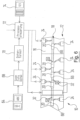
- figure 1 10 denotes a system for coating objects as an example of a surface treatment of an object, which is shown by way of example as a painting system 12, in which objects are painted and of which only a section is shown.
- a painting system 12 in which objects are painted and of which only a section is shown.
- objects to be coated are in figure 1 Vehicle bodies 14 shown.
- the painting installation 10 comprises a painting tunnel 16 as a coating space, in which a conveyor system 18 known per se is arranged, with which the vehicle bodies 14 are conveyed through the painting tunnel 16 .
- the vehicle bodies 14 are provided with a coating in the form of a multilayer paint finish 20, for which purpose the vehicle bodies 14 pass through a number of coating zones 22, of which in figure 1 three coating zones 22a, 22b and 22c are shown from right to left.
- a coating robot in the form of a multi-axis painting robot 24 is arranged in each coating zone 22, as is known per se and by means of which the paintwork 20 is applied to the vehicle body 14.
- each painting robot 24 carries a paint application device, such as a high-speed rotary atomizer 26 .
- the vehicle bodies thus go through a coating process in the form of a painting process.
- sample application robots 28 with a sample application device 30, which in the present exemplary embodiment are designed as a multi-axis printing robot 32 and as a print head 34, the latter working on the principle of an inkjet print head.
- two printing robots 32a and 32b are arranged in the coating zone 22a, whereas only a single printing robot 32c is present in the coating zone 22c.
- the pattern application device 30 is movably guided.
- the sample application device 30 does not have to be carried by its own sample application robot 28 either, but can also be guided by a painting robot 24 .
- this can include, for example, a paint application device and a pattern application device 30 as a type of interchangeable head.
- the vehicle bodies 14 are provided with a functional pattern 36 by means of a coating process with the aid of the pattern application robot 28 .
- This functional pattern 36 can be integrated into the paintwork 20 or applied to it on the outside.
- the sample application robots 28 or the printing robots 32 can also be arranged in a treatment room that is separate from the painting tunnel 16 and through which the vehicle bodies 14 pass after the painting process.
- the functional patterns 36 are printed onto a printing surface 38 of the vehicle body 14.
- a printing surface 38 is a surface area of the vehicle body 14 which is on the outside in the course of the painting process or after its completion and is available for printing.
- FIG. 40 designates a material wall of an object, in the present example a sheet metal wall of a vehicle body 14 .
- the sheet metal wall 40 now carries the paintwork 20, which is shown in FIGS. 2B, 3B, 4B and 5C and there, by way of example, comprises three layers.
- a layer of a primer 42 is first applied to the sheet metal wall 40 .
- the primer 42 is then provided with a coloring top coat 44 .
- a top coat 46 is then applied to the top coat 44 .
- This can be a transparent clear coat or a colored coat.
- Such a painting process is known per se.
- the functional pattern 36 was applied as a single-layer functional pattern 48 to the top coat 44 of the paintwork 20 in a first process step A before the top coat 46 is applied to it.
- the top coat 44 thus forms the printing surface 38.
- the top coat 44 and the single-layer functional sample 48 are then coated with the top coat 46 and thereby sealed to the outside.
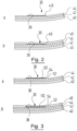
- figure 3 shows a two-layer functional pattern 50 with a first layer 52 and a second layer 54.
- the top coat 44 forms the printing surface 38.
- the first layer 52 is applied by the pattern application robot 28 to the top coat 44 in a first partial step upset.
- the first layer 52 of the two-layer functional model 50 is then covered with the second layer 54 .
- the top coat 44 and the two-layer functional sample 50 are then coated with the top coat 46 .
- a relief pattern 56 is shown as a functional pattern 28, which was also applied to the top coat 44 in a first process step A, which in turn serves as a printing surface 38.
- the relief pattern 56 includes elevations 58 and depressions 60, which can be visually recognized or felt by an observer. So that the relief pattern 56 can still be felt after the painting is complete, in a second process step B, the top coat 46 is applied to the top coat 44 and the relief pattern 56 in such a way that the top coat 46 follows the surface profile of the relief pattern 56, so that the relief contour of the relief pattern 56 finally reflected in the surface profile of the top coat 46.
- the top coat 46 can also be applied as a layer to the relief pattern 56, which levels out the elevations 58 and the depressions 60, so that a smooth paint surface of the vehicle body 14 without structuring is formed in the area of the relief pattern.
- the relief pattern 56 can only be recognized visually.
- FIG 5 a modification is shown in which the relief pattern 56 was not applied to the top coat 44, but rather to the primer 42 in a first process step A, which thus provides the printing surface 38.
- a second process step B the primer 42 and the relief pattern 56 are then covered with the top coat 44, which is then sealed with the top coat 46 in a third process step C.
- the surface contour of the relief pattern 56 on the surface of the top coat 46 is retained.
- the elevations 58 and depressions 60 of the relief pattern 56 are shown in figure 5 not provided with reference marks.
- the top coat 46 or already the top coat 44 can be applied to the relief pattern 65 in such a way that its surface structure is balanced and the top coat 46 again forms a smooth surface without structuring in the area of the relief pattern 56 .
- the functional pattern 36 is printed directly onto the sheet metal wall 40 and then covered by the three layers of primer 42, top coat 44 and top coat 46.
- Functional patterns 36 can now be patterns that can be applied to the used printing surface 38 by means of printing methods known per se, in particular according to the principle of inkjet printers.
- individual samples are interesting, through which a vehicle can already be individualized for the end buyer and end user during the painting process.
- Such individual patterns can be, for example, photos, images, texts, Be patterns and structures or the like that can be specified individually by the end buyer or end user to the manufacturer.
- Such individual patterns can be applied to the inside of the vehicle body 14 as a decorative pattern, for example.
- FIG 1 This is illustrated, for example, by the printing robot 32c in the coating zone 22c, which guides the print head 34 in the interior of the vehicle body 14.
- the printing robot 32c in the coating zone 22c, which guides the print head 34 in the interior of the vehicle body 14.
- a vehicle body 14 can also be provided with individual patterns on the outside, which the printing robot 32a makes clear in the treatment zone 22a. There, the printing robot 32a imprints an opened tailgate 62 of the vehicle body 14.
- the tailgate 62 of the vehicle body 14 can be provided in this way with an individual pattern, which replaces the usual manufacturer's emblem.
- Such individual patterns can be handed over to the manufacturer, for example, as an image 64, which is figure 6 is shown.
- image 64 which is figure 6 is shown.
- items 66 are shown generally, only some of which bear a reference number.
- the image 64 is first converted into a file 68 electronically. If necessary--or if the manufacturer is given a file 68 directly by the customer--a conversion 70 into a data format may also be necessary, which is used by a process controller 72 for the printing robot or robots 32 of the paint shop 12 can be processed. In the present exemplary embodiment, the process controller 72 also communicates with the painting robots 24, which figure 6 is shown by the dashed lines.
- the process controller 72 then coordinates the painting process and controls the painting robots 24 and the printing robots 32 in such a way that the result is an individualized vehicle body 14 or an individualized object 66 which corresponds to the customer's requirements.
- a functional pattern 36 can also be in the form of an information pattern which provides information about or about the coated object, in the present case information about or about the vehicle.
- information patterns can be incorporated in particular into the coating 20 and thus protected against external influences.
- FIG 1 1 illustrates the printing of such a chassis number on a vehicle body 14 by the printing robot 32b in the treatment zone 22a, the non-recognizable print head 34 of which is guided in the engine compartment of the vehicle body 14.
- figure 6 74 designates a data input via which an information pattern can be transferred to the process control 72, which is indicated there by way of example by a barcode and a sequence of digits.
- functional models 36 are also designed as technical models.
- Technical patterns are linked to a technical functionality.
- these include sensors for detecting environmental properties, e.g. light sensors, gas sensors, distance sensors, tactile sensors or the like, as well as solar cells and light-emitting diodes (LEDs) and organic light-emitting diodes (OLEDs).
- LEDs light-emitting diodes
- OLEDs organic light-emitting diodes
- electrical or electronic circuits and electrical conductor tracks, with which other technical patterns or other electrical or electronic assemblies can be connected, can also be printed on as technical patterns.
- Such technical patterns can also be applied to surfaces according to the principle of inkjet printers, which is known in particular for solar cells, distance sensors, electronic circuits, LEDs or OLEDs.
- Functional patterns 36 can also be printed, which fulfill several functions at the same time.
- a printed RFID transponder from which information can be read is both an information pattern and a technical pattern.
- both information patterns and technical patterns can be printed as individual patterns and hidden in a decor, so to speak, to ensure the pure to obscure functionality from the buyer or end user.
- the functional patterns 36 can also always be subsequently applied to an object by means of separate printing robots 32 or also differently guided print heads 34 .
- Additional functional models 36 can also be attached to functional models 36 that are already present. This may be necessary, for example, if the equipment list changes due to the retrofitting of equipment features on a vehicle, which is then stored in an information template adapted to this.
- Functional models 36 can also be applied to an object during or after repairs or maintenance work is carried out. For example, information about the work steps carried out and maintenance or repair work can be attached to the object - also in coded form.
- the individual method steps that are necessary to create the functional model 36 are variable.
- the printing robot 32 can work together with a camera system, whereby the functional model 36 can be attached to the object, in the present exemplary embodiment thus to the vehicle body 14, with the smallest possible positional tolerances and can also be checked after application.
- a printing robot 32 can also carry other treatment units with it, for example in order to cause the functional pattern 36 to flow or, in the case of a multi-layer functional pattern 36, to a layer of the same impede.
- treatment units can be, for example, heat or radiation units, by means of which a printed layer is dried or hardened by heat radiation or electromagnetic radiation.
- All patterns can be designed as a relief pattern 56, as in the Figures 4 and 5 is illustrated.
Landscapes
- Life Sciences & Earth Sciences (AREA)
- Engineering & Computer Science (AREA)
- Wood Science & Technology (AREA)
- Application Of Or Painting With Fluid Materials (AREA)
- Spray Control Apparatus (AREA)
- Coating Apparatus (AREA)
- Automobile Manufacture Line, Endless Track Vehicle, Trailer (AREA)
Description
- Die Erfindung betrifft ein Verfahren zur Oberflächenbehandlung von Fahrzeugkarosserien oder von Teilen davon.
- Bei der Fertigung von vielen Gegenständen werden diese einer Oberflächenbehandlung unterzogen. Hierbei wird die Güte der Oberfläche beispielsweise veredelt und/oder gegen äußere Einflüsse geschützt. Beispielsweise werden Fahrzeugkarosserien oder Teile davon, aber auch eine Vielzahl von anderen Gegenständen wie z.B. Sportgeräte oder dergleichen hierzu mit einer Lackierung versehen.
- Häufig besteht der Wunsch nach einer Individualisierung der Gegenstände, durch welche sich die Gegenstände gegenüber anderen Gegenständen aus einer gleichen Produktionslinie unterscheiden. Dies betrifft die Gegenstände einerseits während des Produktionsprozesses auf Herstellerseite, um beispielsweise Produkt-Informationen mit dem Gegenstand zu verknüpfen. Andererseits wünschen sich häufig die Endkäufer und Endnutzer eines Gegenstandes nach dessen Fertigstellung) dass sich der Gegenstand in individueller Weise von anderen, ansonsten gleichen Gegenständen unterscheidet, um dem eigenen Gegenstand auch eine eigene persönliche Note geben zu können. Hierzu werden Gegenstände beispielsweise nachträglich mit Aufklebern oder dergleichen versehen. Aber auch eine Individualisierung durch technische Merkmale, die einen Gegenstand von einem anderen Gegenstand oder eine erste Produktlinie von einer zweiten Produktlinie unterscheiden, kann gewünscht sein.
- Aus der
DE 10 2010 047808 A1 ist ein Verfahren bekannt, um ein strukturiertes Muster als integrierten Prozessschritt während eines Lackierprozesses auf eine Fahrzeugkarosserie oder eines Teils davon aufzubringen. -
DE 10 2004 044655 A1 offenbart eine Lackier-Vorrichtung zum Lackieren einer gekrümmten Oberfläche, mit einer Lackmaterialausstoß-Einrichtung, mit einer Führungseinrichtung in Form eines Roboterarms und mit einer Steuer-Einrichtung. Ein Reliefmuster wird aufgetragen, wodurch der Luftwiderstand eines Flugzeugs reduziert und der Treibstoffbedarf vermindert werden. -
DE 10 2009 004878 A1 beschreibt ein Verfahren zum Lackieren durch Auftragen von überlappenden Bahnen mittels eines Roboterarms. - Zur Führung des Roboterarms wird ein Muster mittels einer Düse aufgetragen.
- Die
DE 34 45 401 A1 offenbart ein Verfahren, bei dem ein Identifikationsmuster mit der technischen Funktion einer Auslesemöglichkeit der Identifikation des Fahrzeugs ermöglicht, ohne dass das Muster optisch sichtbar ist auf eine Fahrzeugkarosserie aufgetragen wird. Durch die Auswahl von entweder wärmedämmender Farbe oder Metall entsteht dabei die technische Funktion einer Auslesemöglichkeit mittels Temperaturmessgeräten oder Ultraschallsensoren. - Es ist Aufgabe der Erfindung, ein Verfahren der eingangs genannten Art zu schaffen, welches diesen Gedanken Rechnung trägt.
- Diese Aufgabe wird dadurch gelöst dass der Gegenstand mittels eines Beschichtungsvorganges gemäß Anspruch 1 mit einem Funktionsmuster versehen wird.
- Erfindungsgemäß wurde erkannt, dass durch diese Maßnahme eine besonders zuverlässige und beständige Individualisierung erreicht werden kann. Anstatt von leicht ablösbaren Aufklebern oder nachträglichen Anbauten, wie Schildern oder technischen Komponenten oder dergleichen, wird der Gegenstand mit einer Beschichtung versehen, welche die gewünschte Individualisierung herbeiführt. Auf die Art und die Natur eines solchen Funktionsmusters wird weiter unten nochmals im Detail eingegangen.
- Es ist besonders günstig, wenn der Gegenstand im Rahmen eines Lackierprozesses mit dem Funktionsmuster versehen wird, bei welchem der Gegenstand in einem Beschichtungsraum in einem oder mehreren Schritten mit einer Beschichtung versehen wird. Auf diese Weise werden eng verwandte Arbeitsschritte miteinander verknüpft, nämlich die Beschichtung des Gegenstandes mit einer Beschichtung, wie beispielsweise einer Lackierung, einerseits und die Beschichtung des Gegenstandes mit dem Funktionsmuster andererseits.
- Dabei kann das Funktionsmuster in die Beschichtung des Gegenstandes integriert oder außen auf die Beschichtung des Gegenstandes aufgebracht werden. Wenn das Funktionsmuster in die Beschichtung des Gegenstandes integriert wird, kann ein guter Schutz des Funktionsmusters gegen äußere Einflüsse sowie gegen Manipulationen von außen erreicht werden.
- Es ist besonders praktikabel, wenn das Funktionsmuster auf eine Druckoberfläche des Gegenstandes aufgedruckt wird, welche ein Oberflächenbereich des Gegenstandes ist, der im Laufe des Beschichtungsprozesses für die Beschichtung oder nach dessen Vollendung außen liegt und für ein Bedrucken zur Verfügung steht. Eine Druckoberfläche kann also auch im Laufe eines Lackierprozesses durch eine Zwischenschicht eines Lackes gegeben sein und dann später mit einer weiteren Schicht bedeckt werden.
- Dementsprechend kann es von Vorteil sein, wenn die Druckoberfläche auf der Oberfläche einer Materialwand des Gegenstandes oder einer Schicht aus einem Beschichtungsmaterial ausgebildet ist.
- Es ist besonders günstig, wenn das Funktionsmuster ein Individualmuster, ein Informationsmuster oder ein technisches Muster ist. Erfindungsgemäß ist das Funktionsmuster ein technisches Muster in Form eines Sensors zur Erfassung von Umgebungseigenschaften in Form eines Lichtsensors, Gassensors, Abstandssensors, Tastsensors, oder in Form einer Solarzelle oder Leuchtdiode (LED) oder organischen Leuchtdiode (OLED) oder eines elektrischen oder elektronischen Schaltkreises oder einer elektrischen Leiterbahn oder eines RFID-Transponders.
- Auch hierauf wird weiter unten nochmals im Detail eingegangen.
- Wenn das Funktionsmuster als Reliefmuster ausgebildet wird, kann es zusätzlich oder ergänzend ertastbar sein, was in manchen Fällen von Vorteil sein kann. Ein Reliefmuster zeichnet sich neben möglichen anderen Funktionen durch Erhebungen und Vertiefungen aus.
- Nachstehend werden Ausführungsbeispiele der Erfindung anhand der Zeichnungen näher erläutert. In diesen zeigen:
- Figur 1
- schematisch eine Lackierkabine, in der Applikationsroboter und ein Fördersystem angeordnet sind, mit deren Hilfe Fahrzeugkarosserien lackiert und mit einem Funktionsmuster versehen werden;
- Figuren 2 bis 5
- verschiedene Varianten der Erzeugung eines Funktionsmusters;
- Figur 6
- schematisch einen Prozessablauf zur Erzeugung eines Funktionsmusters.
- In
Figur 1 ist mit 10 als Beispiel für eine Oberflächenbehandlung eines Gegenstandes insgesamt eine Anlage zum Beschichten von Gegenständen bezeichnet, die beispielhaft als Lackieranlage 12 gezeigt ist, in welcher Gegenstände lackiert werden und von der lediglich ein Abschnitt gezeigt ist. Als Beispiel für zu beschichtende Gegenstände sind inFigur 1 Fahrzeugkarosserien 14 dargestellt. - Die Lackieranlage 10 umfasst als Beschichtungsraum einen Lackiertunnel 16, in dem ein an und für sich bekanntes Fördersystem 18 angeordnet ist, mit dem die Fahrzeugkarosserien 14 durch den Lackiertunnel 16 hindurch gefördert werden.
- Auf ihrem Weg durch den Lackiertunnel 16 hindurch werden die Fahrzeugkarosserien 14 mit einer Beschichtung in Form einer mehrschichtigen Lackierung 20 versehen, wozu die Fahrzeugkarosserien 14 mehrere Beschichtungszonen 22 durchlaufen, von denen in
Figur 1 von rechts nach links drei Beschichtungszonen 22a, 22b und 22c gezeigt sind. In jeder Beschichtungszone 22 ist ein Beschichtungsroboter in Form eines mehrachsigen Lackierroboters 24 angeordnet, wie er an und für sich bekannt ist und mittels welchem die Lackierung 20 auf die Fahrzeugkarosserie 14 aufgebracht wird. Hierzu führt jeder Lackierroboter 24 eine Lack-Applikationsvorrichtung, wie beispielsweise einen Hochrotationszerstäuber 26, mit sich. Im Lackiertunnel 16 durchlaufen die Fahrzeugkarosserien somit einen Beschichtungsprozess in Form eines Lackierprozesses. - In den Beschichtungszonen 22a und 22c befinden sich neben den dortigen Lackierrobotern 24 noch Muster-Applikationsroboter 28 mit einer Muster-Applikationseinrichtung 30, die beim vorliegenden Ausführungsbeispiel als mehrachsiger Druckroboter 32 und als Druckkopf 34 ausgebildet sind, wobei letzterer nach dem Prinzip eines Tintenstrahldruckkopfes arbeitet. In der Beschichtungszone 22a sind beim vorliegenden Ausführungsbeispiel zwei Druckroboter 32a und 32b angeordnet, wogegen in der Beschichtungszone 22c nur ein einziger Druckroboter 32c vorhanden ist.
- Allgemein ausgedrückt ist die Muster-Applikationseinrichtung 30 beweglich geführt. Die Muster-Applikationseinrichtung 30 muss auch nicht von einem eigenen Muster-Applikationsroboter 28 getragen sein, sondern kann auch von einen Lackierroboter 24 geführt werden. Dieser kann hierzu z.B. eine Lack-Applikationsvorrichtung und eine Muster-Applikationsvorrichtung 30 als eine Art Wechselkopf umfassen.
- Die Fahrzeugkarosserien 14 werden mit Hilfe der Muster-Applikationsroboter 28 mittels eines Beschichtungsvorganges mit einem Funktionsmuster 36 versehen. Dieses Funktionsmuster 36 kann in die Lackierung 20 integriert oder außen auf diese aufgebracht sein. In letztem Fall können die Muster-Applikationsroboter 28 bzw. die Druckroboter 32 auch in einem vom Lackiertunnel 16 getrennten Behandlungsraum angeordnet sein, der von den Fahrzugkarosserien 14 im Anschluss an den Lackiervorgang durchlaufen werden.
- Auf Details zu dem Funktionsmuster 36 wird weiter unten nochmals näher eingegangen.
- Im vorliegenden Fall der Druckroboter 32 werden die Funktionsmuster 36 auf eine Druckoberfläche 38 der Fahrzeugkarosserie 14 aufgedruckt. Eine Druckoberfläche 38 ist dabei ein Oberflächenbereich der Fahrzeugkarosserie 14, der im Laufe des Lackierprozesses oder nach dessen Vollendung außen liegt und für ein Bedrucken zur Verfügung steht.
- Dies ist in den
Figuren 2 bis 5 veranschaulicht. Dort ist mit 40 eine Materialwand eines Gegenstandes, beim vorliegenden Beispiel also eine Blechwand einer Fahrzeugkarosserie 14, bezeichnet. - Die Blechwand 40 trägt nun die Lackierung 20, die in den Figuren 2B, 3B, 4B und 5C gezeigt ist und dort jeweils beispielhaft drei Schichten umfasst. Im Lackierprozess wird zunächst eine Schicht aus einem Primer 42 auf die Blechwand 40 aufgetragen. Der Primer 42 wird dann mit einem farbgebenden Decklack 44 versehen. Auf den Decklack 44 wird dann ein Oberlack 46 aufgetragen. Dieser kann ein transparenter Klarlack oder ein farbiger Lack sein. Ein solcher Lackierprozess ist an und für sich bekannt.
- In
Figur 2 ist veranschaulicht, dass das Funktionsmuster 36 als einschichtiges Funktionsmuster 48 in einem ersten Prozessschritt A auf den Decklack 44 der Lackierung 20 aufgebracht wurde, bevor diese mit dem Oberlack 46 versehen wird. In diesem Fall bildet somit der Decklack 44 die Druckoberfläche 38. In einem zweiten Prozessschritt B wird dann der Decklack 44 und das einschichtige Funktionsmuster 48 mit dem Oberlack 46 beschichtet und hierdurch nach außen versiegelt. -
Figur 3 zeigt ein zweischichtiges Funktionsmuster 50 mit einer ersten Schicht 52 und einer zweiten Schicht 54. Auch hier bildet der Decklack 44 die Druckoberfläche 38. In einem ersten Prozessschritt A wird in einem ersten Teilschritt die erste Schicht 52 durch die Muster-Applikationsroboter 28 auf den Decklack 44 aufgebracht. In einem zweiten Teilschritt des Prozessschrittes A wird dann die erste Schicht 52 des zweischichtigen Funktionsmusters 50 mit der zweiten Schicht 54 bedeckt. In einem zweiten Prozessschritt B wird dann der Decklack 44 und das zweischichtige Funktionsmuster 50 mit dem Oberlack 46 beschichtet. - In
Figur 4 ist als Funktionsmuster 28 ein Reliefmuster 56 gezeigt, welches ebenfalls in einem ersten Prozessschritt A auf den Decklack 44 aufgebracht wurde, die also wiederum als Druckoberfläche 38 dient. Das Reliefmuster 56 umfasst Erhebungen 58 und Vertiefungen 60, welche von einem Betrachter visuell erkannt oder ertastet werden können. Damit das Reliefmuster 56 nach Abschluss der Lackierung ertastbar bleibt, wird der Oberlack 46 in einem zweiten Prozessschritt B derart auf den Decklack 44 und das Reliefmuster 56 aufgetragen, dass der Oberlack 46 dem Oberflächenverlauf des Reliefmusters 56 folgt, so dass sich die Reliefkontur des Reliefmusters 56 schließlich im Oberflächenverlauf des Oberlacks 46 widerspiegelt. - Gegebenenfalls kann der Oberlack 46 auch als Schicht auf das Reliefmuster 56 aufgebracht werden, welche die Erhebungen 58 und die Vertiefungen 60 ausgleicht, so dass im Bereich des Reliefmusters eine glatte Lackoberfläche der Fahrzeugkarosserie 14 ohne Strukturierung ausgebildet ist. In diesem Fall kann das Reliefmuster 56 lediglich visuell erkannt werden.
- In
Figur 5 ist eine Abwandlung gezeigt, bei welcher das Reliefmuster 56 nicht auf den Decklack 44, sondern in einem ersten Prozessschritt A bereits auf den Primer 42 aufgetragen wurde, welcher somit die Druckoberfläche 38 bereitstellt. In einem zweiten Prozessschritt B wird dann der Primer 42 und das Reliefmuster 56 mit dem Decklack 44 bedeckt, die dann in einem dritten Prozessschritt C mit dem Oberlack 46 versiegelt wird. Dabei bleibt die Oberflächenkontur des Reliefmusters 56 an der Oberfläche des Oberlacks 46 erhalten. Der Übersichtlichkeit halber sind die Erhebungen 58 und Vertiefungen 60 des Reliefmusters 56 inFigur 5 nicht mit Bezeugzeichen versehen. - Alternativ können der Oberlack 46 oder bereits der Decklack 44 so auf das Reliefmuster 65 aufgetragen werden, dass dessen Oberflächenstruktur ausgeglichen wird und der Oberlack 46 im Bereich des Reliefmusters 56 wieder eine glatte Oberfläche ohne Strukturierung ausbildet.
- Bei einer hier nicht eigens gezeigten Abwandlung wird das Funktionsmuster 36 direkt auf die Blechwand 40 gedruckt und danach von den drei Schichten aus Primer 42, Decklack 44 und Oberlack 46 abgedeckt.
- Als Funktionsmuster 36 kommen nun Muster in Frage, welche mittels an und für sich bekannter Druckmethoden, insbesondere nach dem Prinzip von Tintenstrahldruckern, auf die genutzte Druckoberfläche 38 aufgebracht werden können.
- Hierbei sind beispielsweise Individualmuster interessant, durch welche ein Fahrzeug bereits beim Lackierprozess für den Endkäufer und Endnutzer individualisiert werden kann. Derartige Individualmuster können z.B. Fotos, Bilder, Texte, Muster und Strukturen oder dergleichen sein, die dem Hersteller von dem Endkäufer oder Endnutzer individuell vorgegeben werden können.
- Derartige Individualmuster können beispielsweise als Dekormuster innen auf die Fahrzeugkarosserie 14 aufgebracht werden. In
Figur 1 veranschaulicht dies z.B. der Druckroboter 32c in der Beschichtungszone 22c, der den Druckkopf 34 in dem Innenraum der Fahrzeugkarosserie 14 führt. Beispielsweise kommt in Betracht, ein Foto oder Bild eines Familienmitglieds des Endkäufers als Dekormuster im Innenraum der Fahrzeugkarosserie aufzudrucken. - Aber auch außen kann eine Fahrzeugkarosserie 14 entsprechend mit Individualmustern versehen werden, was der Druckroboter 32a in der Behandlungszone 22a anschaulich macht. Der Druckroboter 32a bedruckt dort eine geöffnete Heckklappe 62 der Fahrzeugkarosserie 14. Beispielsweise kann die Heckklappe 62 der Fahrzeugkarosserie 14 auf diese Weise mit einem Individualmuster versehen werden, welches das übliche Herstelleremblem ersetzt.
- Derartige Individualmuster können dem Hersteller beispielsweise als Abbild 64 übergeben werden, was in
Figur 6 gezeigt ist. Dort sind abweichend vonFigur 1 mehr Lackierroboter 24 im Lackiertunnel 16 angeordnet und die Druckroboter 32 anders positioniert. Außerdem sind statt Fahrzeugkarosserien 14 allgemein Gegenstände 66 gezeigt, von denen nur einige ein Bezugszeichen tragen. - Das Abbild 64 wird zunächst elektronisch in eine Datei 68 umgewandelt. Gegebenenfalls - oder wenn dem Hersteller vom Kunden direkt eine Datei 68 übergeben wird - kann noch eine Konvertierung 70 in ein Datenformat notwendig sein, welches von einer Prozesssteuerung 72 für den oder die Druckroboter 32 der Lackieranlage 12 verarbeitet werden kann. Die Prozesssteuerung 72 kommuniziert beim vorliegenden Ausführungsbeispiel auch mit den Lackierrobotern 24, was in
Figur 6 anhand der gestrichelten Linien gezeigt ist. - Die Prozesssteuerung 72 koordiniert dann den Lackierprozess und steuert die Lackierroboter 24 und die Druckroboter 32 so an, das im Ergebnis eine individualisierte Fahrzeugkarosserie 14 oder ein individualisierter Gegenstand 66 entsteht, die bzw. der dem Kundenwunsch entspricht.
- Ein Funktionsmuster 36 kann auch als Informationsmuster ausgebildet sein, welche Informationen über den oder zu dem beschichteten Gegenstand liefern, vorliegend also Informationen über das oder zu dem Fahrzeug. Hierzu zählen beispielsweise Serien- oder Produktionsnummern, visuell codierte Produktinformationen wie z.B. Barcodes, QR-Codes oder auch Hologramme, in denen z.B. Ausstattungsmerkmale und -umfänge abgelegt sind, besondere Wartungs- oder Bedienungshinweise, Typenbezeichnungen, Piktogramme, Markennamen und Firmenlogos oder dergleichen. In der oben beschriebenen Weise können solche Informationsmuster insbesondere in die Lackierung 20 eingearbeitet sein und so gegen einen Einfluss von außen geschützt sein.
- Besonders bei Seriennummern kann dies von Vorteil sein. Beispielsweise fällt ein Entfernen und/oder Ändern der an der Fahrzeugkarosserie angebrachten Fahrgestellnummer schnell auf, da hierzu die Lackierung 20 angegriffen und nicht nur ein Schild ausgetauscht werden muss. In
Figur 1 ist der Druck einer solchen Fahrgestellnummer auf eine Fahrzeugkarosserie 14 durch den Druckroboter 32b in der Behandlungszone 22a veranschaulicht, dessen nicht zu erkennender Drucckopf 34 im Motorraum der Fahrzeugkarosserie 14 geführt wird. InFigur 6 ist mit 74 eine Dateneingabe bezeichnet, über welche der Prozesssteuerung 72 ein Informationsmuster übergeben werden kann, welches dort beispielhaft durch einen Barcode und eine Ziffernfolge angedeutet ist. - Erfindungsgemäß sind Funktionsmuster 36 auch als technische Muster ausgebildet. Technische Muster sind mit einer technischen Funktionalität verknüpft. Hierzu zählen erfindungsemäß Sensoren zur Erfassung von Umgebungseigenschaften, z.B. Lichtsensoren, Gassensoren, Abstandssensoren, Tastsensoren oder dergleichen, ebenso wie Solarzellen und Leuchtdioden (LEDs) sowie organischer Leuchtdioden (OLEDs). Auch elektrische oder elektronische Schaltkreise sowie elektrische Leiterbahnen, mit denen wiederum andere technische Muster oder sonstige elektrische oder elektronische Baugruppen verschaltet werden können, können erfindungsgemäß als technische Muster aufgedruckt werden.
- Auch solche technischen Muster können nach dem Prinzip von Tintenstrahldruckern auf Oberflächen aufgetragen werden, was insbesondere für Solarzellen, Abstandssensoren, elektronische Schaltungen, LEDs oder OLEDs bekannt ist.
- Es können auch Funktionsmuster 36 aufgedruckt werden, die mehrere Funktionen zugleich erfüllen. Beispielsweise ist ein aufgedruckter RFID-Transponder, aus welchem Informationen ausgelesen werden können, sowohl ein Informationsmuster als auch ein technisches Muster.
- Auch das Aufdrucken von RFIDs ist aus dem Stand der Technik an und für sich bekannt.
- Darüber hinaus können sowohl Informationsmuster als auch technische Muster als Individualmuster aufgedruckt und gleichsam in einem Dekor versteckt werden, um die reine Funktionalität für den Käufer oder Endnutzer zu verdecken.
- Die Funktionsmuster 36 können auch immer nachträglich auf mittels separater Druckroboter 32 oder auch anders geführter Druckköpfe 34 auf einen Gegenstand aufgebracht werden. Auch können nachträglich zusätzliche Funktionsmuster 36 zu bereits vorhandenen Funktionsmustern 36 angebracht werden. Dies kann z.B. notwendig sein, wenn sich durch das Nachrüsten von Ausstattungsmerkmalen eines Fahrzeugs die Ausstattungsliste ändert, was dann in einem daran angepassten Informationsmuster abgelegt ist.
- Auch bei bzw. nach einer Reparatur oder der Durchführung von Wartungsarbeiten können Funktionsmuster 36 auf einen Gegenstand aufgebracht werden. Beispielsweise können damit Informationen über die durchgeführten Arbeitsschritte und Wartungs- oder Reparaturarbeiten - auch in codierter Form - an dem Gegenstand angebracht werden.
- Abhängig vom Ort, an dem das Funktionsmuster aufgebracht wird, und von der Art und Weise, wie dies geschieht, sind die einzelnen Verfahrensschritte variabel, die zur Erstellung des Funktionsmusters 36 notwendig sind.
- Gegebenenfalls kann der Druckroboter 32 mit einem Kamerasystem zusammenarbeiten, wodurch das Funktionsmuster 36 am Gegenstand, beim vorliegenden Ausführungsbeispiel somit an der Fahrzeugkarosserie 14, mit möglichst geringen Lagetoleranzen angebracht werden kann und nach dem Aufbringen auch kontrolliert werden kann.
- Neben dem Druckkopf 34 kann ein Druckroboter 32 auch weitere Behandlungseinheiten mit sich führen, um beispielsweise ein Verfließen des Funktionsmusters 36 oder bei einem mehrschichtigen Funktionsmuster 36 einer Schicht desselben zu verhindern. Derartige Behandlungseinheiten können z.B. Wärme- oder Strahlungseinheiten sein, durch welche eine aufgedruckte Schicht durch Wärmestrahlung oder elektromagnetische Strahlung getrocknet oder gehärtet wird.
- Alle Muster, seien es Individual-, Informations- oder technische Muster, können als Reliefmuster 56 ausgebildet sein, wie es in den
Figuren 4 und 5 veranschaulicht ist.
Claims (5)
- Verfahren zur Oberflächenbehandlung von Fahrzeugkarosserien oder von Teilen davon, wobei die Fahrzeugkarosserie (14; 66) oder ein Teil davon mittels eines Beschichtungsvorganges mit einem Funktionsmuster (36) versehen wird, und die Fahrzeugkarosserie (14; 66) oder ein Teil davon im Rahmen eines Lackierprozesses mit dem Funktionsmuster (36) versehen wird, bei welchem die Fahrzeugkarosserie (14; 66) oder ein Teil davon in einem Beschichtungsraum (16) in einem oder mehreren Schritten mittels von Lackierrobotern (24; 28) beweglich geführten Lack-Applikationsvorrichtungen mit einer Beschichtung (20) versehen wird, unddie Fahrzeugkarosserie (14; 66) oder ein Teil davon mit Hilfe einer von einem Roboter (24; 28) beweglich geführten Muster-Applikationseinrichtung (30) mit dem Funktionsmuster (36) versehen wird,dadurch gekennzeichnet, dassdas Funktionsmuster (36) ein technisches Muster ist, in Form eines Sensors zur Erfassung von Umgebungseigenschaften in Form eines Lichtsensors, Gassensors, Abstandssensors, Tastsensors, oder in Form einer Solarzelle oder Leuchtdiode (LED) oder organischen Leuchtdiode (OLED) oder eines elektrischen oder elektronischen Schaltkreises oder einer elektrischen Leiterbahn oder eines RFID-Transponders.
- Verfahren nach Anspruch 1, dadurch gekennzeichnet, dass das Funktionsmuster (36) in die Beschichtung (20) des Gegenstandes (14; 66) integriert oder außen auf die Beschichtung (20) des Gegenstandes (14; 66) aufgebracht wird.
- Verfahren nach Anspruch 1 oder 2, dadurch gekennzeichnet, dass das Funktionsmuster (36) auf eine Druckoberfläche (38) des Gegenstandes (14; 66) aufgedruckt wird, welche ein Oberflächenbereich des Gegenstandes (14; 66) ist, der im Laufe des Beschichtungsprozesses für die Beschichtung (20) oder nach dessen Vollendung außen liegt und für ein Bedrucken zur Verfügung steht.
- Verfahren nach Anspruch 3, dadurch gekennzeichnet, dass die Druckoberfläche (38) auf der Oberfläche einer Materialwand (40) des Gegenstandes (14; 66) oder einer Schicht aus einem Beschichtungsmaterial (42, 44, 46) ausgebildet ist.
- Verfahren nach einem der Ansprüche 1 bis 4, dadurch gekennzeichnet, dass das Funktionsmuster (36) als Reliefmuster (56) ausgebildet wird.
Applications Claiming Priority (2)
| Application Number | Priority Date | Filing Date | Title |
|---|---|---|---|
| DE102012011254A DE102012011254A1 (de) | 2012-06-06 | 2012-06-06 | Verfahren zur Oberflächenbehandlung von Gegenständen |
| PCT/EP2013/001577 WO2013182280A2 (de) | 2012-06-06 | 2013-05-29 | Verfahren zur oberflächenbehandlung von gegenständen |
Publications (2)
| Publication Number | Publication Date |
|---|---|
| EP2858759A2 EP2858759A2 (de) | 2015-04-15 |
| EP2858759B1 true EP2858759B1 (de) | 2023-04-05 |
Family
ID=48670481
Family Applications (1)
| Application Number | Title | Priority Date | Filing Date |
|---|---|---|---|
| EP13730480.4A Active EP2858759B1 (de) | 2012-06-06 | 2013-05-29 | Verfahren zur oberflächenbehandlung von gegenständen |
Country Status (5)
| Country | Link |
|---|---|
| US (1) | US9566611B2 (de) |
| EP (1) | EP2858759B1 (de) |
| CN (1) | CN104395003A (de) |
| DE (1) | DE102012011254A1 (de) |
| WO (1) | WO2013182280A2 (de) |
Families Citing this family (5)
| Publication number | Priority date | Publication date | Assignee | Title |
|---|---|---|---|---|
| DE102013002433A1 (de) | 2013-02-11 | 2014-08-14 | Dürr Systems GmbH | Lackierverfahren und Lackieranlage für Zierstreifen |
| DE102014018339B4 (de) | 2014-12-10 | 2020-08-20 | Audi Ag | Verfahren zur Applikation eines Oberflächenmusters |
| DE102016112787A1 (de) | 2016-07-12 | 2016-10-06 | Eisenmann Se | Verfahren zum Lackieren einer Kraftfahrzeugkarosserie |
| DE102018114101B4 (de) * | 2018-06-13 | 2022-03-10 | Humbaur Gmbh | Fahrzeugaufbau und Anhänger mit einem solchen Fahrzeugaufbau |
| US11745206B2 (en) | 2020-08-24 | 2023-09-05 | Columbus Industries, Inc. | Filtering apparatus with at least one filter unit |
Citations (4)
| Publication number | Priority date | Publication date | Assignee | Title |
|---|---|---|---|---|
| DE3445401A1 (de) * | 1984-12-13 | 1986-06-26 | Rosorius, Gerhard, 2085 Quickborn | Fahrzeug, insbesondere kraftfahrzeug |
| DE102004044655A1 (de) * | 2004-09-15 | 2006-03-30 | Airbus Deutschland Gmbh | Lackier-Vorrichtung, Lackier-Anordnung, Verfahren zum Lackieren einer gekrümmten Oberfläche eines Objekts und Verwendung einer Inkjet-Einrichtung zum Lackieren eines Flugzeugs |
| DE102009004878A1 (de) * | 2009-01-16 | 2010-07-29 | Bauer, Jörg R. | Verfahren zum Beschichten, insbesondere Lackieren, einer Oberfläche sowie digitales Beschichtungssystem |
| DE102010047808A1 (de) * | 2009-11-05 | 2011-05-12 | Heidelberger Druckmaschinen Aktiengesellschaft | Verfahren zum mehrfarbigen, permanenten Lackieren eines Produkts |
Family Cites Families (25)
| Publication number | Priority date | Publication date | Assignee | Title |
|---|---|---|---|---|
| US2403084A (en) * | 1942-01-28 | 1946-07-02 | Westinghouse Electric Corp | Application of markings to surfaces |
| DE2719450B2 (de) * | 1977-04-30 | 1981-03-26 | Eugen 67122 Altrip Schneider | Folienbahn aus Kunststoff zur Verarbeitung auf formatbildenden, automatischen Maschinen mit einer Abzugsvorrichtung |
| FR2413940A1 (fr) * | 1978-01-10 | 1979-08-03 | Renault | Constitution d'un revetement de sol, notamment pour l'habitacle d'un vehicule automobile |
| US4299637A (en) * | 1978-06-14 | 1981-11-10 | John R. Koza | Method of making a game ticket |
| DE2945217C2 (de) | 1979-11-09 | 1982-03-11 | J.H. Benecke Gmbh, 3000 Hannover | Verfahren zur dekorativen Musterung von Oberflächen |
| US4513027A (en) * | 1981-12-29 | 1985-04-23 | Tropicana Products, Inc. | UPC Scannable marking composition and applications thereof |
| US4431321A (en) * | 1982-01-29 | 1984-02-14 | Product Identification Corporation | Computer controlled marking apparatus |
| DE4335308C2 (de) * | 1993-10-16 | 1995-12-14 | Daimler Benz Ag | Kennzeichnung von Fahrzeugen zur Erschwerung von Diebstahl und oder unbefugter Veräußerung |
| US5436027A (en) * | 1993-12-23 | 1995-07-25 | The Boeing Company | Method of applying a coating design |
| US5925402A (en) * | 1998-07-15 | 1999-07-20 | Morton International, Inc. | Method of forming a hidden identification using powder coating |
| AU2977800A (en) * | 1999-02-01 | 2000-08-18 | National Paper & Packaging | System and method for identification of manufacturing components |
| US6376016B1 (en) * | 2000-06-14 | 2002-04-23 | Ford Global Tech., Inc. | Method for painting a vehicle with at least two colors |
| DE20100608U1 (de) * | 2001-01-15 | 2001-04-26 | Kampmeier, René, 63263 Neu-Isenburg | Haushaltsgegenstände mit Antihaftschicht und Dekorschicht |
| JP3883832B2 (ja) * | 2001-10-02 | 2007-02-21 | セメダインヘンケル株式会社 | 制振材付車体パネル及び制振材塗布装置 |
| US20030108725A1 (en) * | 2001-12-10 | 2003-06-12 | Matthew Hamilton | Visual images produced by surface patterning |
| WO2006041451A1 (en) * | 2004-09-29 | 2006-04-20 | Durr Industries, Inc. | Production paint shop design |
| US20070166463A1 (en) * | 2005-01-28 | 2007-07-19 | Kelly Craig J | Paint spray booth |
| EP2229282A1 (de) * | 2007-12-31 | 2010-09-22 | Exatec, LLC. | Vorrichtung und verfahren zum drucken dreidimensionaler artikel |
| WO2009115201A2 (de) * | 2008-03-20 | 2009-09-24 | Dürr Systems GmbH | Lackierroboter und zugehöriges betriebsverfahren |
| US9375746B2 (en) * | 2008-06-05 | 2016-06-28 | Durr Systems Gmbh | Compact paint booth |
| DE102009004877B4 (de) * | 2009-01-16 | 2015-10-08 | Jörg R. Bauer | Bauteil mit einem Grundkörper und einer darauf mittels eines digitalen Beschichtungssystems aufgebrachten Schicht |
| CN101879799A (zh) | 2009-05-04 | 2010-11-10 | 富准精密工业(深圳)有限公司 | 壳体及其制造方法 |
| DE102010006665B4 (de) | 2010-02-03 | 2021-05-27 | Bayerische Motoren Werke Aktiengesellschaft | Verfahren zum Herstellen eines Farbkontrastmusters |
| RU2445700C1 (ru) * | 2010-07-05 | 2012-03-20 | Общество с ограниченной ответственностью "Флуоресцентные информационные технологии" | Верифицируемая символьная метка прямого нанесения и способ ее изготовления |
| US8628823B2 (en) * | 2011-06-16 | 2014-01-14 | Xerox Corporation | Methods and systems for making patterned photoreceptor outer layer |
-
2012
- 2012-06-06 DE DE102012011254A patent/DE102012011254A1/de not_active Ceased
-
2013
- 2013-05-29 WO PCT/EP2013/001577 patent/WO2013182280A2/de not_active Ceased
- 2013-05-29 EP EP13730480.4A patent/EP2858759B1/de active Active
- 2013-05-29 CN CN201380029763.2A patent/CN104395003A/zh active Pending
- 2013-05-29 US US14/405,869 patent/US9566611B2/en active Active
Patent Citations (4)
| Publication number | Priority date | Publication date | Assignee | Title |
|---|---|---|---|---|
| DE3445401A1 (de) * | 1984-12-13 | 1986-06-26 | Rosorius, Gerhard, 2085 Quickborn | Fahrzeug, insbesondere kraftfahrzeug |
| DE102004044655A1 (de) * | 2004-09-15 | 2006-03-30 | Airbus Deutschland Gmbh | Lackier-Vorrichtung, Lackier-Anordnung, Verfahren zum Lackieren einer gekrümmten Oberfläche eines Objekts und Verwendung einer Inkjet-Einrichtung zum Lackieren eines Flugzeugs |
| DE102009004878A1 (de) * | 2009-01-16 | 2010-07-29 | Bauer, Jörg R. | Verfahren zum Beschichten, insbesondere Lackieren, einer Oberfläche sowie digitales Beschichtungssystem |
| DE102010047808A1 (de) * | 2009-11-05 | 2011-05-12 | Heidelberger Druckmaschinen Aktiengesellschaft | Verfahren zum mehrfarbigen, permanenten Lackieren eines Produkts |
Also Published As
| Publication number | Publication date |
|---|---|
| WO2013182280A3 (de) | 2014-03-27 |
| WO2013182280A2 (de) | 2013-12-12 |
| CN104395003A (zh) | 2015-03-04 |
| US20150174612A1 (en) | 2015-06-25 |
| US9566611B2 (en) | 2017-02-14 |
| DE102012011254A1 (de) | 2013-12-12 |
| EP2858759A2 (de) | 2015-04-15 |
Similar Documents
| Publication | Publication Date | Title |
|---|---|---|
| DE102012212469B4 (de) | Verfahren zum Bedrucken einer Oberfläche und Vorrichtung zum Bedrucken einer Oberfläche | |
| DE102009021608B4 (de) | Einrichtung und Verfahren zum Lackieren gekrümmter Außenoberflächen eines Luftfahrzeuges | |
| DE102009004877B4 (de) | Bauteil mit einem Grundkörper und einer darauf mittels eines digitalen Beschichtungssystems aufgebrachten Schicht | |
| EP3723991B1 (de) | Verfahren zur herstellung eines wenigstens zwei farbschichten aufweisenden bauteils für ein kraftfahrzeug | |
| EP3966646B1 (de) | Verfahren zur analyse von qualitätsmängeln | |
| DE102012017538A1 (de) | Verfahren zum Bebildern und/oder Lackieren der Oberfläche von Gegenständen | |
| EP2858759A2 (de) | Verfahren zur oberflächenbehandlung von gegenständen | |
| EP2858825B1 (de) | Verfahren zum bedrucken einer zylindrischen druckoberfläche einer getränkedose und bedruckte getränkedose | |
| EP2319630A1 (de) | Verfahren zum mehrfarbigen, permanenten Lackieren eines Produkts | |
| DE102013004144B4 (de) | Verfahren und Vorrichtung zur Oberflächenbehandlung von Gegenständen | |
| EP3804863A1 (de) | Applikationsverfahren und applikationsanlage | |
| EP2208541A2 (de) | Verfahren zum Beschichten, insbesondere Lackieren, einer Oberfläche sowie digitales Beschichtungssystem | |
| DE102014006651A1 (de) | Beschichtungsanlage zur Beschichtung von Bauteilen, insbesondere zur Lackierung von Kraftfahrzeugkarosseriebauteilen | |
| EP2953733A1 (de) | Lackierverfahren und lackieranlage für zierstreifen | |
| EP4338024B1 (de) | Betriebsverfahren für eine beschichtungsanlage und beschichtungsanlage zur ausführung des betriebsverfahrens | |
| DE102017215725A1 (de) | Vorrichtung und Verfahren zur Applikation eines Dicht- und/oder Beschichtungsstoffes | |
| DE102020127852A1 (de) | Betriebsverfahren für eine Beschichtungsanlage und entsprechend angepasste Beschichtungsanlage | |
| DE102019206833A1 (de) | Verfahren zur Analyse von Qualitätsmängeln | |
| EP4041553A1 (de) | Beschichtungsvorrichtung und verfahren mit prägestation und druckstation | |
| DE102009050601B4 (de) | Bauteil mit Beschichtung und Beschichtungsverfahren | |
| DE102016210186A1 (de) | Verfahren zum Bedrucken eines 3D-Objektes | |
| DE102013021371A1 (de) | Verfahren und Vorrichtung zur Herstellung von Formteilen in einer Pressenlinie | |
| DE102008046124A1 (de) | Verfahren zur Oberflächenbehandlung von Bauteilen | |
| DE102015208560A1 (de) | Verfahren und Vorrichtung zur Individualisierung von Interieur- und/oder Exterieurbauteilen eines Kraftfahrzeugs mittels Beschriftungslaser | |
| EP2367639B1 (de) | Verfahren zum aufbringen einer lackfolie als flüssigfolie |
Legal Events
| Date | Code | Title | Description |
|---|---|---|---|
| PUAI | Public reference made under article 153(3) epc to a published international application that has entered the european phase |
Free format text: ORIGINAL CODE: 0009012 |
|
| 17P | Request for examination filed |
Effective date: 20141120 |
|
| AK | Designated contracting states |
Kind code of ref document: A2 Designated state(s): AL AT BE BG CH CY CZ DE DK EE ES FI FR GB GR HR HU IE IS IT LI LT LU LV MC MK MT NL NO PL PT RO RS SE SI SK SM TR |
|
| AX | Request for extension of the european patent |
Extension state: BA ME |
|
| DAX | Request for extension of the european patent (deleted) | ||
| RAP1 | Party data changed (applicant data changed or rights of an application transferred) |
Owner name: EISENMANN SE |
|
| STAA | Information on the status of an ep patent application or granted ep patent |
Free format text: STATUS: EXAMINATION IS IN PROGRESS |
|
| 17Q | First examination report despatched |
Effective date: 20181005 |
|
| 19U | Interruption of proceedings before grant |
Effective date: 20190731 |
|
| 19W | Proceedings resumed before grant after interruption of proceedings |
Effective date: 20200803 |
|
| GRAP | Despatch of communication of intention to grant a patent |
Free format text: ORIGINAL CODE: EPIDOSNIGR1 |
|
| STAA | Information on the status of an ep patent application or granted ep patent |
Free format text: STATUS: GRANT OF PATENT IS INTENDED |
|
| INTG | Intention to grant announced |
Effective date: 20221031 |
|
| RAP1 | Party data changed (applicant data changed or rights of an application transferred) |
Owner name: B+M SURFACE SYSTEMS GMBH |
|
| GRAS | Grant fee paid |
Free format text: ORIGINAL CODE: EPIDOSNIGR3 |
|
| GRAA | (expected) grant |
Free format text: ORIGINAL CODE: 0009210 |
|
| STAA | Information on the status of an ep patent application or granted ep patent |
Free format text: STATUS: THE PATENT HAS BEEN GRANTED |
|
| AK | Designated contracting states |
Kind code of ref document: B1 Designated state(s): AL AT BE BG CH CY CZ DE DK EE ES FI FR GB GR HR HU IE IS IT LI LT LU LV MC MK MT NL NO PL PT RO RS SE SI SK SM TR |
|
| REG | Reference to a national code |
Ref country code: GB Ref legal event code: FG4D Free format text: NOT ENGLISH |
|
| REG | Reference to a national code |
Ref country code: DE Ref legal event code: R096 Ref document number: 502013016364 Country of ref document: DE |
|
| REG | Reference to a national code |
Ref country code: CH Ref legal event code: EP |
|
| REG | Reference to a national code |
Ref country code: AT Ref legal event code: REF Ref document number: 1557846 Country of ref document: AT Kind code of ref document: T Effective date: 20230415 |
|
| REG | Reference to a national code |
Ref country code: IE Ref legal event code: FG4D Free format text: LANGUAGE OF EP DOCUMENT: GERMAN |
|
| REG | Reference to a national code |
Ref country code: LT Ref legal event code: MG9D |
|
| REG | Reference to a national code |
Ref country code: NL Ref legal event code: MP Effective date: 20230405 |
|
| PG25 | Lapsed in a contracting state [announced via postgrant information from national office to epo] |
Ref country code: NL Free format text: LAPSE BECAUSE OF FAILURE TO SUBMIT A TRANSLATION OF THE DESCRIPTION OR TO PAY THE FEE WITHIN THE PRESCRIBED TIME-LIMIT Effective date: 20230405 |
|
| PG25 | Lapsed in a contracting state [announced via postgrant information from national office to epo] |
Ref country code: SE Free format text: LAPSE BECAUSE OF FAILURE TO SUBMIT A TRANSLATION OF THE DESCRIPTION OR TO PAY THE FEE WITHIN THE PRESCRIBED TIME-LIMIT Effective date: 20230405 Ref country code: PT Free format text: LAPSE BECAUSE OF FAILURE TO SUBMIT A TRANSLATION OF THE DESCRIPTION OR TO PAY THE FEE WITHIN THE PRESCRIBED TIME-LIMIT Effective date: 20230807 Ref country code: NO Free format text: LAPSE BECAUSE OF FAILURE TO SUBMIT A TRANSLATION OF THE DESCRIPTION OR TO PAY THE FEE WITHIN THE PRESCRIBED TIME-LIMIT Effective date: 20230705 Ref country code: ES Free format text: LAPSE BECAUSE OF FAILURE TO SUBMIT A TRANSLATION OF THE DESCRIPTION OR TO PAY THE FEE WITHIN THE PRESCRIBED TIME-LIMIT Effective date: 20230405 |
|
| P01 | Opt-out of the competence of the unified patent court (upc) registered |
Effective date: 20231009 |
|
| PG25 | Lapsed in a contracting state [announced via postgrant information from national office to epo] |
Ref country code: RS Free format text: LAPSE BECAUSE OF FAILURE TO SUBMIT A TRANSLATION OF THE DESCRIPTION OR TO PAY THE FEE WITHIN THE PRESCRIBED TIME-LIMIT Effective date: 20230405 Ref country code: PL Free format text: LAPSE BECAUSE OF FAILURE TO SUBMIT A TRANSLATION OF THE DESCRIPTION OR TO PAY THE FEE WITHIN THE PRESCRIBED TIME-LIMIT Effective date: 20230405 Ref country code: LV Free format text: LAPSE BECAUSE OF FAILURE TO SUBMIT A TRANSLATION OF THE DESCRIPTION OR TO PAY THE FEE WITHIN THE PRESCRIBED TIME-LIMIT Effective date: 20230405 Ref country code: LT Free format text: LAPSE BECAUSE OF FAILURE TO SUBMIT A TRANSLATION OF THE DESCRIPTION OR TO PAY THE FEE WITHIN THE PRESCRIBED TIME-LIMIT Effective date: 20230405 Ref country code: IS Free format text: LAPSE BECAUSE OF FAILURE TO SUBMIT A TRANSLATION OF THE DESCRIPTION OR TO PAY THE FEE WITHIN THE PRESCRIBED TIME-LIMIT Effective date: 20230805 Ref country code: HR Free format text: LAPSE BECAUSE OF FAILURE TO SUBMIT A TRANSLATION OF THE DESCRIPTION OR TO PAY THE FEE WITHIN THE PRESCRIBED TIME-LIMIT Effective date: 20230405 Ref country code: GR Free format text: LAPSE BECAUSE OF FAILURE TO SUBMIT A TRANSLATION OF THE DESCRIPTION OR TO PAY THE FEE WITHIN THE PRESCRIBED TIME-LIMIT Effective date: 20230706 Ref country code: AL Free format text: LAPSE BECAUSE OF FAILURE TO SUBMIT A TRANSLATION OF THE DESCRIPTION OR TO PAY THE FEE WITHIN THE PRESCRIBED TIME-LIMIT Effective date: 20230405 |
|
| PG25 | Lapsed in a contracting state [announced via postgrant information from national office to epo] |
Ref country code: FI Free format text: LAPSE BECAUSE OF FAILURE TO SUBMIT A TRANSLATION OF THE DESCRIPTION OR TO PAY THE FEE WITHIN THE PRESCRIBED TIME-LIMIT Effective date: 20230405 |
|
| REG | Reference to a national code |
Ref country code: CH Ref legal event code: PL |
|
| REG | Reference to a national code |
Ref country code: DE Ref legal event code: R097 Ref document number: 502013016364 Country of ref document: DE |
|
| PG25 | Lapsed in a contracting state [announced via postgrant information from national office to epo] |
Ref country code: SK Free format text: LAPSE BECAUSE OF FAILURE TO SUBMIT A TRANSLATION OF THE DESCRIPTION OR TO PAY THE FEE WITHIN THE PRESCRIBED TIME-LIMIT Effective date: 20230405 |
|
| PG25 | Lapsed in a contracting state [announced via postgrant information from national office to epo] |
Ref country code: MC Free format text: LAPSE BECAUSE OF FAILURE TO SUBMIT A TRANSLATION OF THE DESCRIPTION OR TO PAY THE FEE WITHIN THE PRESCRIBED TIME-LIMIT Effective date: 20230405 |
|
| REG | Reference to a national code |
Ref country code: BE Ref legal event code: MM Effective date: 20230531 |
|
| PG25 | Lapsed in a contracting state [announced via postgrant information from national office to epo] |
Ref country code: SM Free format text: LAPSE BECAUSE OF FAILURE TO SUBMIT A TRANSLATION OF THE DESCRIPTION OR TO PAY THE FEE WITHIN THE PRESCRIBED TIME-LIMIT Effective date: 20230405 Ref country code: SK Free format text: LAPSE BECAUSE OF FAILURE TO SUBMIT A TRANSLATION OF THE DESCRIPTION OR TO PAY THE FEE WITHIN THE PRESCRIBED TIME-LIMIT Effective date: 20230405 Ref country code: RO Free format text: LAPSE BECAUSE OF FAILURE TO SUBMIT A TRANSLATION OF THE DESCRIPTION OR TO PAY THE FEE WITHIN THE PRESCRIBED TIME-LIMIT Effective date: 20230405 Ref country code: MC Free format text: LAPSE BECAUSE OF FAILURE TO SUBMIT A TRANSLATION OF THE DESCRIPTION OR TO PAY THE FEE WITHIN THE PRESCRIBED TIME-LIMIT Effective date: 20230405 Ref country code: LU Free format text: LAPSE BECAUSE OF NON-PAYMENT OF DUE FEES Effective date: 20230529 Ref country code: EE Free format text: LAPSE BECAUSE OF FAILURE TO SUBMIT A TRANSLATION OF THE DESCRIPTION OR TO PAY THE FEE WITHIN THE PRESCRIBED TIME-LIMIT Effective date: 20230405 Ref country code: DK Free format text: LAPSE BECAUSE OF FAILURE TO SUBMIT A TRANSLATION OF THE DESCRIPTION OR TO PAY THE FEE WITHIN THE PRESCRIBED TIME-LIMIT Effective date: 20230405 Ref country code: CZ Free format text: LAPSE BECAUSE OF FAILURE TO SUBMIT A TRANSLATION OF THE DESCRIPTION OR TO PAY THE FEE WITHIN THE PRESCRIBED TIME-LIMIT Effective date: 20230405 Ref country code: CH Free format text: LAPSE BECAUSE OF NON-PAYMENT OF DUE FEES Effective date: 20230531 Ref country code: LI Free format text: LAPSE BECAUSE OF NON-PAYMENT OF DUE FEES Effective date: 20230531 |
|
| PLBE | No opposition filed within time limit |
Free format text: ORIGINAL CODE: 0009261 |
|
| STAA | Information on the status of an ep patent application or granted ep patent |
Free format text: STATUS: NO OPPOSITION FILED WITHIN TIME LIMIT |
|
| REG | Reference to a national code |
Ref country code: IE Ref legal event code: MM4A |
|
| 26N | No opposition filed |
Effective date: 20240108 |
|
| GBPC | Gb: european patent ceased through non-payment of renewal fee |
Effective date: 20230705 |
|
| PG25 | Lapsed in a contracting state [announced via postgrant information from national office to epo] |
Ref country code: IE Free format text: LAPSE BECAUSE OF NON-PAYMENT OF DUE FEES Effective date: 20230529 |
|
| PG25 | Lapsed in a contracting state [announced via postgrant information from national office to epo] |
Ref country code: IE Free format text: LAPSE BECAUSE OF NON-PAYMENT OF DUE FEES Effective date: 20230529 Ref country code: GB Free format text: LAPSE BECAUSE OF NON-PAYMENT OF DUE FEES Effective date: 20230705 |
|
| PG25 | Lapsed in a contracting state [announced via postgrant information from national office to epo] |
Ref country code: SI Free format text: LAPSE BECAUSE OF FAILURE TO SUBMIT A TRANSLATION OF THE DESCRIPTION OR TO PAY THE FEE WITHIN THE PRESCRIBED TIME-LIMIT Effective date: 20230405 |
|
| PG25 | Lapsed in a contracting state [announced via postgrant information from national office to epo] |
Ref country code: SI Free format text: LAPSE BECAUSE OF FAILURE TO SUBMIT A TRANSLATION OF THE DESCRIPTION OR TO PAY THE FEE WITHIN THE PRESCRIBED TIME-LIMIT Effective date: 20230405 Ref country code: IT Free format text: LAPSE BECAUSE OF FAILURE TO SUBMIT A TRANSLATION OF THE DESCRIPTION OR TO PAY THE FEE WITHIN THE PRESCRIBED TIME-LIMIT Effective date: 20230405 Ref country code: BE Free format text: LAPSE BECAUSE OF NON-PAYMENT OF DUE FEES Effective date: 20230531 |
|
| REG | Reference to a national code |
Ref country code: AT Ref legal event code: MM01 Ref document number: 1557846 Country of ref document: AT Kind code of ref document: T Effective date: 20230529 |
|
| PG25 | Lapsed in a contracting state [announced via postgrant information from national office to epo] |
Ref country code: AT Free format text: LAPSE BECAUSE OF NON-PAYMENT OF DUE FEES Effective date: 20230529 |
|
| PG25 | Lapsed in a contracting state [announced via postgrant information from national office to epo] |
Ref country code: AT Free format text: LAPSE BECAUSE OF NON-PAYMENT OF DUE FEES Effective date: 20230529 |
|
| PG25 | Lapsed in a contracting state [announced via postgrant information from national office to epo] |
Ref country code: BG Free format text: LAPSE BECAUSE OF FAILURE TO SUBMIT A TRANSLATION OF THE DESCRIPTION OR TO PAY THE FEE WITHIN THE PRESCRIBED TIME-LIMIT Effective date: 20230405 |
|
| PG25 | Lapsed in a contracting state [announced via postgrant information from national office to epo] |
Ref country code: BG Free format text: LAPSE BECAUSE OF FAILURE TO SUBMIT A TRANSLATION OF THE DESCRIPTION OR TO PAY THE FEE WITHIN THE PRESCRIBED TIME-LIMIT Effective date: 20230405 |
|
| PGFP | Annual fee paid to national office [announced via postgrant information from national office to epo] |
Ref country code: DE Payment date: 20250521 Year of fee payment: 13 |
|
| PGFP | Annual fee paid to national office [announced via postgrant information from national office to epo] |
Ref country code: FR Payment date: 20250521 Year of fee payment: 13 |
|
| PG25 | Lapsed in a contracting state [announced via postgrant information from national office to epo] |
Ref country code: CY Free format text: LAPSE BECAUSE OF FAILURE TO SUBMIT A TRANSLATION OF THE DESCRIPTION OR TO PAY THE FEE WITHIN THE PRESCRIBED TIME-LIMIT; INVALID AB INITIO Effective date: 20130529 |
|
| PG25 | Lapsed in a contracting state [announced via postgrant information from national office to epo] |
Ref country code: HU Free format text: LAPSE BECAUSE OF FAILURE TO SUBMIT A TRANSLATION OF THE DESCRIPTION OR TO PAY THE FEE WITHIN THE PRESCRIBED TIME-LIMIT; INVALID AB INITIO Effective date: 20130529 |
|
| PG25 | Lapsed in a contracting state [announced via postgrant information from national office to epo] |
Ref country code: TR Free format text: LAPSE BECAUSE OF FAILURE TO SUBMIT A TRANSLATION OF THE DESCRIPTION OR TO PAY THE FEE WITHIN THE PRESCRIBED TIME-LIMIT Effective date: 20230405 |