EP2858715B1 - Current control for electrotransport drug delivery - Google Patents
Current control for electrotransport drug delivery Download PDFInfo
- Publication number
- EP2858715B1 EP2858715B1 EP13804530.7A EP13804530A EP2858715B1 EP 2858715 B1 EP2858715 B1 EP 2858715B1 EP 13804530 A EP13804530 A EP 13804530A EP 2858715 B1 EP2858715 B1 EP 2858715B1
- Authority
- EP
- European Patent Office
- Prior art keywords
- transistor
- voltage
- current
- patient
- patient contact
- Prior art date
- Legal status (The legal status is an assumption and is not a legal conclusion. Google has not performed a legal analysis and makes no representation as to the accuracy of the status listed.)
- Not-in-force
Links
Images


Classifications
-
- A—HUMAN NECESSITIES
- A61—MEDICAL OR VETERINARY SCIENCE; HYGIENE
- A61N—ELECTROTHERAPY; MAGNETOTHERAPY; RADIATION THERAPY; ULTRASOUND THERAPY
- A61N1/00—Electrotherapy; Circuits therefor
- A61N1/02—Details
- A61N1/025—Digital circuitry features of electrotherapy devices, e.g. memory, clocks, processors
-
- A—HUMAN NECESSITIES
- A61—MEDICAL OR VETERINARY SCIENCE; HYGIENE
- A61N—ELECTROTHERAPY; MAGNETOTHERAPY; RADIATION THERAPY; ULTRASOUND THERAPY
- A61N1/00—Electrotherapy; Circuits therefor
- A61N1/02—Details
- A61N1/04—Electrodes
- A61N1/0404—Electrodes for external use
- A61N1/0408—Use-related aspects
- A61N1/0428—Specially adapted for iontophoresis, e.g. AC, DC or including drug reservoirs
-
- A—HUMAN NECESSITIES
- A61—MEDICAL OR VETERINARY SCIENCE; HYGIENE
- A61N—ELECTROTHERAPY; MAGNETOTHERAPY; RADIATION THERAPY; ULTRASOUND THERAPY
- A61N1/00—Electrotherapy; Circuits therefor
- A61N1/02—Details
- A61N1/08—Arrangements or circuits for monitoring, protecting, controlling or indicating
-
- A—HUMAN NECESSITIES
- A61—MEDICAL OR VETERINARY SCIENCE; HYGIENE
- A61N—ELECTROTHERAPY; MAGNETOTHERAPY; RADIATION THERAPY; ULTRASOUND THERAPY
- A61N1/00—Electrotherapy; Circuits therefor
- A61N1/18—Applying electric currents by contact electrodes
- A61N1/20—Applying electric currents by contact electrodes continuous direct currents
- A61N1/30—Apparatus for iontophoresis, i.e. transfer of media in ionic state by an electromotoric force into the body, or cataphoresis
-
- A—HUMAN NECESSITIES
- A61—MEDICAL OR VETERINARY SCIENCE; HYGIENE
- A61N—ELECTROTHERAPY; MAGNETOTHERAPY; RADIATION THERAPY; ULTRASOUND THERAPY
- A61N1/00—Electrotherapy; Circuits therefor
- A61N1/18—Applying electric currents by contact electrodes
- A61N1/32—Applying electric currents by contact electrodes alternating or intermittent currents
- A61N1/325—Applying electric currents by contact electrodes alternating or intermittent currents for iontophoresis, i.e. transfer of media in ionic state by an electromotoric force into the body
Definitions
- the present description relates generally to an electrotransport drug delivery device.
- the description is directed to a constant current supply circuit which has improved safety.
- the invention is set out in the appended claims.
- a variety of drug delivery systems including automatic drug delivery systems, are known. Because the consequences of delivering an inappropriate dosage (e.g., too much or too little) of a drug can be life threatening, it is of critical importance that drug delivery systems be extremely accurate. Drug delivery systems that are configured to deliver medication to patients must be configured to prevent even unlikely accidental delivery events. In particular, drug delivery systems that electrically delivery drug to a patient, including transdermal or other electrotransport drug delivery devices, be prevented from accidentally providing drug to the patient.
- electrotransport refers generally to the delivery of an agent (e.g., a drug) through a membrane, such as skin, mucous membrane, or nails.
- an agent e.g., a drug
- the delivery is induced or aided by application of an electrical potential.
- a beneficial therapeutic agent may be introduced into the systemic circulation of a human body by electrotransport delivery through the skin.
- electromigration also called iontophoresis
- electro-osmosis involves the flow of a liquid. The liquid contains the agent to be delivered, under the influence of an electric field.
- electrotransport involves the formation of transiently-existing pores in a biological membrane by the application of an electric field.
- An agent can be delivered through the pores either passively (i.e., without electrical assistance) or actively (i.e., under the influence of an electric potential).
- electrotransport should be given its broadest possible interpretation so that it includes the electrically induced or enhanced transport of at least one agent, which may be charged, uncharged, or a mixture thereof, regardless of the specific mechanism or mechanisms by which the agent actually is transported.
- electrotransport devices use at least two electrodes that are in electrical contact with some portion of the skin, nails, mucous membrane, or other surface of the body.
- One electrode commonly called the “donor” or “active” electrode, is the electrode from which the agent is delivered into the body.
- the other electrode typically termed the “counter” or “return” electrode, serves to close the electrical circuit through the body.
- the agent to be delivered is positively charged, i.e., a cation
- the anode is the active or donor electrode
- the cathode serves to complete the circuit.
- an agent is negatively charged, i.e., an anion
- the cathode is the donor electrode.
- both the anode and cathode may be considered donor electrodes if both anionic and cationic agent ions, or if uncharged dissolved agents, are to be delivered.
- electrotransport delivery systems generally require at least one reservoir or source of the agent to be delivered to the body.
- donor reservoirs include a pouch or cavity, a porous sponge or pad, and a hydrophilic polymer or a gel matrix.
- Such donor reservoirs are electrically connected to, and positioned between, the anode or cathode and the body surface, to provide a fixed or renewable source of one or more agents or drugs.
- Electrotransport devices also have an electrical power source such as one or more batteries. Typically, one pole of the power source is electrically connected to the donor electrode, while the opposite pole is electrically connected to the counter electrode.
- some electrotransport devices have an electrical controller that controls the current applied through the electrodes, thereby regulating the rate of agent delivery.
- passive flux control membranes, adhesives for maintaining device contact with a body surface, insulating members, and impermeable backing members are some other potential components of an electrotransport device.
- Small, self-contained electrotransport drug delivery devices adapted to be worn on the skin for extended periods of time have been proposed. See, e.g., U.S. Pat. No. 6171294 , U.S. Pat. No. 6881208 , U.S. Pat. No. 5843014 , U.S. Pat. No. 6181963 , U.S. Pat. No. 7027859 , U.S. Pat. No. 6975902 , and U.S. Pat. No. 6,216,033 .
- These electrotransport agent delivery devices typically utilize an electrical circuit to electrically connect the power source (e.g., a battery) and the electrodes.
- the electrical components in such miniaturized iontophoretic drug delivery devices are also preferably miniaturized, and may be in the form of either integrated circuits (i.e., microchips) or small printed circuits.
- Electronic components such as batteries, resistors, pulse generators, capacitors, etc. are electrically connected to form an electronic circuit that controls the amplitude, polarity, timing waveform shape, etc. of the electric current supplied by the power source.
- Other examples of small, self-contained electrotransport delivery devices are disclosed in U.S. 5,224,927 ; U.S. Pat. No. 5,203,768 ; U.S. Pat. No. 5,224,928 ; and U.S. Pat. No. 5,246,418 .
- Constant current supplies for variable resistance loads such as those appropriate for use with an electrotransport drug delivery device have been previously described, however such systems require the use of the cathode to determine the voltage and/or current at the cathode.
- US 5,804,957 to Coln describes a constant current supply system for a variable resistance load.
- This system includes a constant current circuit connected to a second output terminal (e.g., anode) for providing a predetermined current to the load (patient) and a constant control circuit.
- a voltage supply control circuit monitors the voltage at the second terminal across the constant current circuit and adjusts the voltage supply to maintain the second terminal at a preselected voltage for maintaining the predetermined current to the variable resistance load. See, e.g., FIG. 1 , which illustrates a prior art system including a voltage control circuit that directly monitors the cathode (via a comparator "throttle" element 140).
- described herein are methods, devices and systems for monitoring and controlling electrotransport drug delivery devices including indirectly monitoring and controlling the circuit not directly connected to the patient terminal (e.g., cathode) using a switching element.
- WO-A-97/07854 discloses a drug delivery system in accordance with the precharacterizing section of claim 1.
- an electrotransport drug delivery system having a constant current supply, the system comprising:
- the first patient contact may also be connected indirectly to the power source.
- the current control transistor may be controlled by an amplifier receiving input from a microcontroller. Any appropriate transistor may be used.
- the transistor may be a FET or a bipolar transistor.
- the second patient contact may be connected to the drain of the transistor.
- the sensing circuit is configured to compare the voltage at the transistor to a threshold voltage.
- the sensing circuit may provide input to a feedback circuit.
- this feedback circuit may provide an alarm based on the comparison between the voltage at the transistor (e.g., at the gate of the transistor when the drain is patient-contacting) and the threshold voltage to indicate constant current cannot be maintained.
- the feedback circuit may automatically control the power source based on the comparison between the voltage at the transistor and the threshold voltage to maintain constant current while minimizing power consumption. For example, in some variations, the current may be maintained at about 170 ⁇ A.
- electrotransport drug delivery systems having a constant current supply
- the system comprising: a power source; a first patient contact connected to the power source; a second patient contact connected to a transistor (e.g., a drain of a transistor); a current control feedback circuit for providing a control signal to the transistor when the connection between the first patient contact and the second patient contact is closed; wherein the transistor is connected to the second patient contact; and a sensing circuit for measuring a voltage applied at the transistor when the connection is closed; wherein the second patient contact is connected to the current control feedback circuit and sensing circuit only though the transistor.
- the second patient contact may be connected to the drain of the transistor, which is separate from the feedback/sensing circuit that may be connected to the gate of the transistor.
- the transistor may be any appropriate transistor, including a bipolar transistor and/or a field-effect transistor (FET).
- FET field-effect transistor
- the second patient contact may be connected to a drain of the transistor, and the control signal may comprise a voltage applied to a gate of the transistor.
- the transistor is a bipolar transistor, and the second patient contact is connected to a collector, while the control signal comprises a current applied to the base of the bipolar transistor.
- the control signal may be a voltage and/or a current applied to the transistor.
- control signal provided to the transistor may be controlled by an amplifier receiving input from a microcontroller.
- the feedback circuit may control the voltage applied to the power source. For example, in some variations, the feedback circuit compares the transistor (e.g., gate) voltage to a reference voltage. The feedback circuit controls the power source based on the comparison between the transistor gate voltage and the reference voltage. The feedback circuit may provide a power source sufficient to deliver a constant current. For example, the feedback circuit may provide a power source sufficient to deliver a constant current of about 170 ⁇ A. The feedback circuit may include a digital to analogue converter for providing a constant current.
- the sensing circuit may be isolated (e.g., electrically isolated) from the first and second patient contacts by the transistor.
- the transistor may be located between the second patient contact and a sense resistor.
- the first patient contact may be an anode and the second patient contact may be a cathode.
- the connection between the first patient contact and the second patient contact is typically configured to be closed (e.g., connected) by a patient's skin.
- Also described herein are methods for operating an electrotransport drug delivery system including a constant current supply the method comprising: contacting a patient's skin with an anode and cathode to form a connection between the anode and cathode; applying an anode voltage to the anode; providing a control signal to a transistor (e.g., gate) connected to the cathode (e.g., at the drain); detecting a voltage at the transistor, wherein the cathode is isolated from the voltage detection by the transistor; comparing the transistor voltage to a threshold voltage; and controlling the anode voltage applied to the anode based on the comparison between the transistor voltage and the threshold voltage.
- a transistor e.g., gate
- the methods may include the use of any appropriate transistor.
- the transistor may be a FET and the control signal comprises a voltage applied to a gate of the transistor.
- the anode voltage may be applied to the anode in response to an input.
- the control signal applied to the transistor may be provided to the transistor by an amplifier, the amplifier isolated from the anode and the cathode by the transistor.
- any appropriate control signal may be used, in particular an electrical voltage and/or a current.
- the current provided from the transistor is a constant current.
- the provided current may be controlled to be about 170 ⁇ A.
- the method includes adjusting the voltage applied to the anode based on the comparison of the transistor voltage to the threshold voltage.
- Electrotransport techniques may include iontophoresis, electroosmosis, and electroporation.
- Electrotransport devices such as iontophoretic devices are known in the art.
- One electrode which may be referred to as the active or donor electrode, is the electrode from which the active agent is delivered into the body.
- the other electrode which may be referred to as the counter or return electrode, serves to close the electrical circuit through the body.
- the circuit is completed by connection of the electrodes to a source of electrical energy, and usually to circuitry capable of controlling the current passing through the device when the device is "on" delivering current. If the substance to be driven into the body is ionic and is positively charged, then the positive electrode (the anode) will be the active electrode and the negative electrode (the cathode) will serve as the counter electrode. If the ionic substance to be delivered is negatively charged, then the cathodic electrode will be the active electrode and the anodic electrode will be the counter electrode.
- a switch-operated therapeutic agent delivery device can provide single or multiple doses of a therapeutic agent to a patient by activating a switch. Upon activation, such a device delivers a therapeutic agent to a patient.
- a patient-controlled device offers the patient the ability to self- administer a therapeutic agent as the need arises.
- the therapeutic agent can be an analgesic agent that a patient can administer whenever sufficient pain is felt.
- any appropriate drug may be delivered by the devices described herein.
- the drug may be an analgesic such as fentanyl (e.g., fentanyl HCL) or sufentanil.
- the different parts of the electrotransport system are stored separately and connected together for use.
- examples of electrotransport devices having parts being connected together before use include those described in U.S. Pat. No. 5,320,597 (Sage, Jr. et al ); U.S. Pat. No. 4,731,926 (Sibalis ), U.S. Pat. No. 5,358,483 (Sibalis ), U.S. Pat. No. 5,135,479 (Sibalis et al. ), UK Patent Publication GB2239803 (Devane et al ), U.S. Pat. No. 5,919,155 (Lattin et al. ), U.S. Pat. No.
- the systems and devices described herein include an anode and cathode for the electrotransport of a drug or drugs into the patient (e.g., through the skin or other membrane) and a controller for controlling the delivery (e.g., turning the delivery on or off); all of the variations described herein may also include an off-current module for monitoring the anode and cathode when the device is off (but still powered) to determine if there is a potential and/or current (above a threshold value) between the anode and cathode when the controller for device has otherwise turned the device "off" so that it should not be delivering drug to the patient.
- the controller may include an activation controller (e.g., an activation module or activation circuitry) for regulating the when the device is on, applying current/voltage between the anode and cathode and thereby delivering drug.
- the term "user” indicates anyone who uses the device, whether a healthcare professional, a patient, or other individual, with the aim of delivering a therapeutic agent to a patient.
- the devices described herein may include control logic and/or circuitry for regulating the application of current by the device.
- FIG. 2 illustrates a schematic for controlling the application of current to deliver drug.
- a feedback circuit may be controlled or regulated by a controller and be part of (or separate from) the drug delivery circuit.
- the controller and circuit may include hardware, software, firmware, or some combination thereof (including control logic).
- a system may include an anode, cathode and feedback circuit.
- the feedback circuit may form part (or be used by) the drug delivery module to provide current between the anode and cathode and deliver drug.
- the device may also include a controller controlling operation of the device.
- the controller may include a processor or ASIC.
- the feedback circuit may be referred to as a type of self-test that is performed by the device.
- FIG. 3 illustrates one variation of a feedback circuit for controlling the current and/or voltage applied across the patient electrodes (anode and cathode), and is included and described in greater detail below in the context of FIG. 4 .
- FIG. 4 illustrates one variation of a diagram illustrating the circuit controlling the application of current to deliver drug to a patient.
- the drug dose is regulated by the control of the current through the electrodes (anode to cathode).
- the current in this example is programmable (e.g., using a 10 bit DAC), but may be preset.
- the target current may be preset to deliver a dose using a current of 170 ⁇ A, as illustrated.
- the dotted line schematically indicates ASIC components; this integrated circuit may be separate from the Rsense resistor.
- the patient tissue completes the circuit between the anode and cathode elements.
- Rsense is on the printed circuit board.
- the Rsense may be on the circuit board (e.g., but not within the ASICS).
- the Rsense and everything within the dotted box may be on the printed circuit board.
- the anode and the cathode may be connected to the patient.
- VHV the voltage source that applies the voltage to deliver a current and therefore drive delivery of drug.
- a Vboost may also be included as part of (or in connection with) the VHV.
- a switch, S1 may be included as a software-enabled switch to control the application of voltage to the anode.
- the S1 switch may act as a safety feature to control (via software) when current is not delivered.
- the voltage may be turned off completely and the switch opened so that even if there were some other voltage present, the anode would be floating. Thus, current could not be pulled through the anode to cathode because the anode is floating (and there is no source of electrons to pull current through, since it is a completely open circuit).
- the M2 switch is a transistor (e.g., a field effect transistor) that acts as a valve to control the flow of current.
- the M2 switch may be referred to as a current control valve or throttle that regulates the current flow down to Rsense resistor, where it goes to the ground.
- the current is throttled by the M2 switch, which may allow control of the current at various levels. For example, in FIG. 4 , the current level is set to be approximately 170uA.
- Rsense may be used to set the current range, and/or the maximum value. A square wave of current may be delivered.
- M2 may be regulated by an amplifier (e.g., Amp1).
- Amp1 is an analogue amplifier; the input to Amp1 is a digital to analogue converter (DAC), which is set with the target 170 ⁇ A level.
- DAC digital to analogue converter
- a microcontroller may be used to set a digital signal using an analogue to digital converter, corresponding to the target delivery current (e.g., 170 ⁇ A).
- the controller e.g., microcontroller
- the controller may be configured so that when no current is to be delivered the DAC may be set to 0 and when current is to be delivered, it may be set to 170uA, providing an analogue output to AMP1 that allows current to flow to Rsense.
- the input to M2 may be used to monitor the voltage at the transistor gate using a comparator, e.g., CMP1.
- the voltage at the gate is compared to a threshold (Vthreshold). If the voltage at the gate of M2 is low, it may be increased, and if it is high, it may be decreased. This feedback may be used to adjust VHV, as illustrated in FIG. 4 .
- cathode is connected only to the current control transistor and not directly connected to the sensing circuit, potential faults in the sensing circuit are isolated from the second patient contact and could not result in additional current flow from anode to cathode, and therefore could not result in additional drug delivered to the patient.
- the voltage may be changed to set the current with that DAC and AMP1.
- the current may be set to 170uA, and the control system described herein prevents it from going over 170uA, providing a constant current source.
- the M2 throttles the maximum amount of current to limit it to 170uA, allowing the voltage to be adjusted.
- the control and monitoring circuit may do this by adjusting the voltage to automatically drop the voltage as necessary. Monitoring the gate at M2 to maintain saturation so that the source voltage VHV value is kept above the level sufficient to deliver current at the set (e.g., 170 ⁇ A) value. Below the saturation level, the gate may deliver less than 170uA.
- the voltage is allowed to drop until it reaches a limit at which it is saturated; and as soon as this threshold is reached, the comparator may sense that the saturation and may adjust the voltage back up.
- This feedback takes place at the level of the M2 gate (throttle) and provides a constant feedback loop where it is constantly comparing the gate of the M2 to a threshold value.
- this feedback loop occurs at the throttle, e.g., rather than the cathode (by, for example, monitoring the voltage at the cathode), additional benefits may be realized.
- Monitoring the voltage at that gate (M2) to control the VHV allows control of the boost voltage without altering (e.g., touching) the cathode at all, e.g., maintaining the monitoring and control aspects of the system in electrical isolation. This allows separation of the control aspect from a risk management aspect of the device, preventing the device from applying inappropriate current and thereby drug.
- self-checks measuring the anode-cathode voltage may be performed independently of the control of the voltage and/or current across the anode and cathode, since the cathode (and/or anode) is not used for monitoring. Instead, the cathode is used to deliver the drug.
- This configuration allows control of the voltage to reduce power consumption, and/or monitoring and controlling the voltage without having to monitor at the cathode, resulting in an efficiency of the system by monitoring at the throttle point where the system can meet safety objectives while only making measurements at the anode and cathode that are related to current flow through the anode cathode.
- the cathode does not require connection of a measurement line to the electrode (e.g., cathode).
- Control of the voltage is therefore independent of safety features such as error detection (e.g., leak current detection). Further, this architecture separates the voltage control mechanism from such an error detection mechanism.
- Error detection mechanisms may include (e.g., within the ASICS) an analogue to digital convertor and the analogue to digital convertor multiplexed to measure the voltage at the anode, the cathode, the VHV voltage, or the like.
- the feedback detection and control of the voltage and current may be regulated from the cathode (e.g., gate M2) rather than the level of the cathode.
- the advantage of this logical separation may include making only measurements on that anode and cathode that are related to whether or not there is leakage current present (whether or not there is a safety problem). Measurements at the gate M2 may be constantly ongoing (e.g., every couple of clock ticks); it is not necessary to measure at the cathode in this configuration, so that the cathode remains isolated from the feedback circuit through the gate M2. The anode cathode measurement is independent verification that there is no current flowing there. By configuring the system in this manner, the cathode is isolated from the feedback that is controlling the voltage. Separation permits the feedback mechanism to be separate from the actual patient connection delivering the current.
- the voltage is less critical for patient safety and the monitoring and controlling of the voltage is configured to provide efficiency of the system and the battery power.
- Current may flow through the drain to the source of the transistor without requiring additional circuitry between the cathode and ground, reducing the chance for malfunction (e.g., additional current flow) through this additional current path.
- Patient safety can be dramatically affected by even small errors in the circuitry.
- the system is limited so that the only connections to the anode/cathode are those that must be there, as shown and described herein.
- the systems and methods described herein use a gate (e.g., transistor M2) to isolate the patient connections, e.g., anode and cathode, from the feedback module used to control the applied voltage and to regulate the current between the patient connections.
- the feedback module is configured as a circuit including a comparator that compares the voltage on the transistor to a threshold voltage.
- this circuit regulates the current between the patient connections so that it rides at or below the target current level (e.g., 170 ⁇ A).
- the circuit may sense when the current is above 170uA.
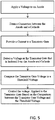
- FIG. 5 schematically illustrates one variation of a method for regulating the voltage and/or current across the patient connections (e.g., anode and cathode) of an electrotransport drug delivery system.
- a pair of patient connections are configured to contact a patient tissue (e.g., skin) to complete the patient circuit.
- the first patient connection (in some configurations the anode, in other configurations, the cathode) is connected to a driving voltage source.
- the connection between the driving voltage source and the first patient connection may be regulated by a switch or gate, which may be regulated or controlled (e.g., by a microcontroller).
- the second patient connection (e.g., in some variations a cathode, in other variations an anode) is then connected in series to a transistor drain (or other throttle element), and a feedback module for monitoring and controlling the current and voltage applied between the first and second patient connections are isolated from the second patient connection by this transistor gate.
- a transistor drain or other throttle element
- a voltage is first applied to the first patient connection (e.g., anode) after or before a connection is made by skin contact between the first and second patient connections.
- Current is then provided to the transistor drain downstream of the second patient contact, and a feedback module determines the voltage at the transistor gate in isolation of the first and second patient contacts.
- the voltage at the transistor gate is compared to a threshold voltage and this comparison is used to adjust the applied voltage at the first patient connection.
- a target current may be provided (e.g., from a microcontroller) to the transistor to regulate the current between the first and second patient connections.
- the constant current supply described above may be used to regulate the dosing of the system to deliver a target current (e.g., drug delivery current) at a low voltage even with variable patient resistances.
- a target current e.g., drug delivery current
- the circuit shown in FIGS. 3 and 4 may be used to provide a dose of drug by delivering a predetermined 170 ⁇ A drug delivery current over a dosing period (e.g., a 10 minute dose).
- the circuit controlling the anode and cathode shown in FIG. 3 and 4 includes a control block containing circuitry to connect the output of the voltage boost converter (VHV) to the anode electrode (EL_A) through the switch S1.
- VHV voltage boost converter
- EL_A anode electrode
- a 10 bit DAC is used to configure the current output to a set value proportional to the desired dosing current.
- the DAC drives AMP1 which controls the current flowing through EL_A and EL_C by driving the gate of M2.
- the source of M2 determines the current flow through Rsense which causes the voltage drop that is fed back into AMP1.
- Rsense As the skin resistance between EL_A and EL_C varies, so does the current through Rsense, which triggers a change in the output of AMP1.
- AMP1 becomes saturated if there is not sufficient voltage to deliver the programmed current with the resistance between EL_A and EL_C.
- Driver functions are available to control and monitor various the points of this circuit.
Applications Claiming Priority (2)
| Application Number | Priority Date | Filing Date | Title |
|---|---|---|---|
| US13/493,314 US8428709B1 (en) | 2012-06-11 | 2012-06-11 | Current control for electrotransport drug delivery |
| PCT/US2013/029114 WO2013187951A1 (en) | 2012-06-11 | 2013-03-05 | Current control for electrotransport drug delivery |
Publications (3)
| Publication Number | Publication Date |
|---|---|
| EP2858715A1 EP2858715A1 (en) | 2015-04-15 |
| EP2858715A4 EP2858715A4 (en) | 2016-01-06 |
| EP2858715B1 true EP2858715B1 (en) | 2017-04-19 |
Family
ID=48094932
Family Applications (1)
| Application Number | Title | Priority Date | Filing Date |
|---|---|---|---|
| EP13804530.7A Not-in-force EP2858715B1 (en) | 2012-06-11 | 2013-03-05 | Current control for electrotransport drug delivery |
Country Status (18)
| Country | Link |
|---|---|
| US (2) | US8428709B1 (ru) |
| EP (1) | EP2858715B1 (ru) |
| JP (1) | JP6363070B2 (ru) |
| KR (1) | KR20150023004A (ru) |
| CN (1) | CN104487132B (ru) |
| AU (1) | AU2013274873B2 (ru) |
| BR (1) | BR112014030823A2 (ru) |
| CA (1) | CA2874983A1 (ru) |
| DK (1) | DK2858715T3 (ru) |
| ES (1) | ES2635242T3 (ru) |
| IL (1) | IL235936A0 (ru) |
| IN (1) | IN2015DN00012A (ru) |
| MX (1) | MX342033B (ru) |
| NZ (1) | NZ702360A (ru) |
| PT (1) | PT2858715T (ru) |
| RU (1) | RU2637560C2 (ru) |
| SG (1) | SG11201408039YA (ru) |
| WO (1) | WO2013187951A1 (ru) |
Families Citing this family (9)
| Publication number | Priority date | Publication date | Assignee | Title |
|---|---|---|---|---|
| US8428709B1 (en) | 2012-06-11 | 2013-04-23 | Incline Therapeutics, Inc. | Current control for electrotransport drug delivery |
| US8428708B1 (en) | 2012-05-21 | 2013-04-23 | Incline Therapeutics, Inc. | Self-test for analgesic product |
| FR3015299B1 (fr) * | 2013-12-20 | 2017-10-06 | Oreal | Dispositif d'iontophorese a gestion independante de courant |
| FR3015300B1 (fr) | 2013-12-20 | 2018-03-02 | L'oreal | Dispositif d'iontophorese a reservoir |
| JP5885803B1 (ja) * | 2014-10-09 | 2016-03-16 | 株式会社ホーマーイオン研究所 | イオン導入用電気刺激装置。 |
| ES2885062T3 (es) | 2017-06-28 | 2021-12-13 | Fundacion Tecnalia Res & Innovation | Dispositivo para la administración transdérmica controlada y vigilada de principios activos y uso del mismo |
| CN108106971A (zh) * | 2018-02-13 | 2018-06-01 | 常州华佳医疗器械有限公司 | 一种新型智能透皮和口腔给药设备及方法 |
| CN108671392A (zh) * | 2018-06-19 | 2018-10-19 | 常州华佳医疗器械有限公司 | 一种用于表皮皮肤供电的电路控制系统 |
| RU2736855C1 (ru) * | 2020-05-11 | 2020-11-20 | Альберт Петрович Притыко | Генератор для электропорации |
Family Cites Families (115)
| Publication number | Priority date | Publication date | Assignee | Title |
|---|---|---|---|---|
| US3521641A (en) * | 1967-09-14 | 1970-07-28 | Harry B Farensbach | Electronic apparatus for inducing sleep |
| US4141359A (en) | 1976-08-16 | 1979-02-27 | University Of Utah | Epidermal iontophoresis device |
| JPS5810066A (ja) | 1981-07-10 | 1983-01-20 | 株式会社アドバンス | イオントフオレ−ゼ用プラスタ−構造体 |
| US4731926A (en) | 1985-02-19 | 1988-03-22 | Drug Delivery Systems Inc. | Method of manufacturing disposable and/or replenishable transdermal drug applicators |
| US4856188A (en) | 1984-10-12 | 1989-08-15 | Drug Delivery Systems Inc. | Method for making disposable and/or replenishable transdermal drug applicators |
| US5224928A (en) | 1983-08-18 | 1993-07-06 | Drug Delivery Systems Inc. | Mounting system for transdermal drug applicator |
| US5135479A (en) | 1983-08-18 | 1992-08-04 | Drug Delivery Systems, Inc. | Programmable control and mounting system for transdermal drug applicator |
| US4588580B2 (en) | 1984-07-23 | 1999-02-16 | Alaz Corp | Transdermal administration of fentanyl and device therefor |
| US5135477A (en) | 1984-10-29 | 1992-08-04 | Medtronic, Inc. | Iontophoretic drug delivery |
| US4752285B1 (en) | 1986-03-19 | 1995-08-22 | Univ Utah Res Found | Methods and apparatus for iontophoresis application of medicaments |
| US4698582A (en) | 1986-07-23 | 1987-10-06 | Motorola, Inc. | Power driver having short circuit protection |
| US4878892A (en) | 1987-02-10 | 1989-11-07 | Drug Delivery Systems Inc. | Electrolytic transdermal delivery of polypeptides |
| US4822802A (en) | 1987-02-24 | 1989-04-18 | Alza Corporation | Method of fentanly administration for postoperative pain relief |
| US5080646A (en) | 1988-10-03 | 1992-01-14 | Alza Corporation | Membrane for electrotransport transdermal drug delivery |
| US4931046A (en) | 1987-05-15 | 1990-06-05 | Newman Martin H | Iontophoresis drug delivery system |
| EP0398960B1 (en) | 1988-01-21 | 1995-12-06 | Massachusetts Institute Of Technology | Transport of molecules across tissue using electroporation |
| US5169382A (en) | 1988-10-03 | 1992-12-08 | Alza Corporation | Membrane for electrotransport transdermal drug delivery |
| US5057072A (en) | 1988-10-28 | 1991-10-15 | Medtronic, Inc. | Iontophoresis electrode |
| US5006108A (en) | 1988-11-16 | 1991-04-09 | Noven Pharmaceuticals, Inc. | Apparatus for iontophoretic drug delivery |
| US5199155A (en) | 1989-07-05 | 1993-04-06 | S.N.C. Livbag | Method for manufacture of a cold-gas pyrotechnic generator |
| US5320597A (en) | 1991-02-08 | 1994-06-14 | Becton, Dickinson And Company | Device and method for renewing electrodes during iontophoresis |
| US5232448A (en) | 1989-12-05 | 1993-08-03 | Prime Medical Products | Patient-controlled analgesia device |
| IT1244030B (it) | 1989-12-21 | 1994-06-28 | Elan Corp Plc | Dispostitivo in due parti per la somministrazione controllata di un ingrediente |
| US5047007A (en) | 1989-12-22 | 1991-09-10 | Medtronic, Inc. | Method and apparatus for pulsed iontophoretic drug delivery |
| US5084008A (en) | 1989-12-22 | 1992-01-28 | Medtronic, Inc. | Iontophoresis electrode |
| US5207752A (en) | 1990-03-30 | 1993-05-04 | Alza Corporation | Iontophoretic drug delivery system with two-stage delivery profile |
| EP0522043B1 (en) | 1990-03-30 | 2003-10-15 | Alza Corporation | Iontophoretic delivery device |
| US5213568A (en) | 1990-03-30 | 1993-05-25 | Medtronic Inc. | Activity controlled electrotransport drug delivery device |
| US5147297A (en) | 1990-05-07 | 1992-09-15 | Alza Corporation | Iontophoretic delivery device |
| US5224927A (en) | 1990-11-01 | 1993-07-06 | Robert Tapper | Iontophoretic treatment system |
| US5254081A (en) | 1991-02-01 | 1993-10-19 | Empi, Inc. | Multiple site drug iontophoresis electronic device and method |
| JP2507478Y2 (ja) | 1991-06-26 | 1996-08-14 | 株式会社エンヤシステム | ウエ―ハ反転貼付装置 |
| US5203768A (en) | 1991-07-24 | 1993-04-20 | Alza Corporation | Transdermal delivery device |
| US5246418A (en) | 1991-12-17 | 1993-09-21 | Becton Dickinson And Company | Iontophresis system having features for reducing skin irritation |
| USH1324H (en) | 1992-09-08 | 1994-06-07 | Cobe Laboratories, Inc. | Extracorporeal circulation system |
| US5306235A (en) | 1992-09-30 | 1994-04-26 | Becton Dickinson And Company | Failsafe iontophoresis drug delivery system |
| US5644463A (en) | 1992-10-20 | 1997-07-01 | University Of Washington | Adaptive sequential controller with minimum switching energy |
| DE69328042T2 (de) | 1992-12-31 | 2000-11-16 | Alza Corp | Elektrotransporteinrichtung |
| JPH0662433U (ja) | 1993-02-15 | 1994-09-02 | 日本航空電子工業株式会社 | 防水型パネルスイッチユニット |
| US5445609A (en) | 1993-05-28 | 1995-08-29 | Alza Corporation | Electrotransport agent delivery device having a disposable component and a removable liner |
| US5458569A (en) | 1993-06-08 | 1995-10-17 | Becton Dickinson And Company | Wearable iontophoresis system |
| USD352357S (en) | 1993-08-06 | 1994-11-08 | Becton Dickinson And Company | Iontophoretic drug delivery system |
| KR970000259B1 (ko) | 1993-08-19 | 1997-01-08 | 주식회사 삼보컴퓨터 | Ac 파형을 이용한 모니터 전력 제어 방법 및 그 장치 |
| FR2709670B1 (fr) | 1993-09-10 | 1995-10-20 | Asulab Sa | Dispositif en trois modules pour l'administration transdermique de médicaments par électrophorèse ou iontophorèse. |
| JP2818999B2 (ja) | 1993-11-22 | 1998-10-30 | ドラッグ デリバリー システムズ インコーポレイテッド | 経皮薬剤アプリケータ |
| AU2286995A (en) | 1994-04-08 | 1995-10-30 | Alza Corporation | Electrotransport system with ion exchange competitive ion capture |
| US7027859B1 (en) | 1994-09-26 | 2006-04-11 | Alza Corporation | Electrotransport delivery device having improved safety and reduced abuse potential |
| US5551953A (en) | 1994-10-31 | 1996-09-03 | Alza Corporation | Electrotransport system with remote telemetry link |
| US5697896A (en) | 1994-12-08 | 1997-12-16 | Alza Corporation | Electrotransport delivery device |
| US5562607A (en) | 1995-01-18 | 1996-10-08 | Alza Corporation | Electrotransport device having reusable controller power saver |
| US5941846A (en) | 1995-03-13 | 1999-08-24 | Alaris Medical Systems, Inc. | Method and apparatus for power connection in a modular patient care system |
| US5843014A (en) | 1995-03-24 | 1998-12-01 | Alza Corporation | Display for an electrotransport delivery device |
| USD372098S (en) | 1995-05-15 | 1996-07-23 | Alza Corporation | Electrotransport drug delivery system |
| AU714537C (en) | 1995-05-15 | 2001-11-08 | Alza Corporation | Electrotransport device having reusable controller |
| IE960312A1 (en) | 1995-06-02 | 1996-12-11 | Alza Corp | An electrotransport delivery device with voltage boosting¹circuit |
| US6425892B2 (en) | 1995-06-05 | 2002-07-30 | Alza Corporation | Device for transdermal electrotransport delivery of fentanyl and sufentanil |
| US6216033B1 (en) | 1996-05-22 | 2001-04-10 | Alza Corporation | Device for transdermal electrotransport delivery of fentanyl and sufentanil |
| US6881208B1 (en) | 1995-06-05 | 2005-04-19 | Joseph B. Phipps | Method and device for transdermal electrotransport delivery of fentanyl and sufentanil |
| CA2218369C (en) | 1995-06-05 | 2010-02-09 | Alza Corporation | Transdermal electrotransport delivery of fentanyl and sufentanil |
| US6355025B1 (en) | 1995-06-07 | 2002-03-12 | Alza Corporation | Adjustable electrotransport drug delivery using a fixed output controller |
| US6167301A (en) | 1995-08-29 | 2000-12-26 | Flower; Ronald J. | Iontophoretic drug delivery device having high-efficiency DC-to-DC energy conversion circuit |
| US5688232A (en) | 1995-09-28 | 1997-11-18 | Becton Dickinson And Company | Iontophoretic drug delivery device having an improved controller |
| US5718562A (en) | 1995-11-02 | 1998-02-17 | Abbott Laboratories | Interface module for use with an NCT-based pumping mechanism and NCT-based cassette |
| USD384745S (en) | 1996-01-23 | 1997-10-07 | Alza Corporation | Electrotransport drug delivery system |
| FR2747313B1 (fr) | 1996-04-16 | 1998-06-05 | Lhd Lab Hygiene Dietetique | Dispositif d'administration transdermique de medicaments par ionophorese |
| US5879143A (en) | 1996-04-26 | 1999-03-09 | Sims Deltec, Inc. | Reservoir enclosure adaptors and methods |
| US6086572A (en) | 1996-05-31 | 2000-07-11 | Alza Corporation | Electrotransport device and method of setting output |
| US5928196A (en) | 1996-08-14 | 1999-07-27 | Sims Deltec, Inc. | Control module cassette locks and methods |
| US6029083A (en) | 1997-04-04 | 2000-02-22 | Becton, Dickinson And Company | Circuit and method for automatically turning off an iontophoresis system |
| US5804957A (en) * | 1997-08-13 | 1998-09-08 | Analog Devices, Inc. | Constant current supply system for a variable resistance load |
| US6047208A (en) | 1997-08-27 | 2000-04-04 | Becton, Dickinson And Company | Iontophoretic controller |
| US5983133A (en) | 1997-09-29 | 1999-11-09 | Becton, Dickinson And Company | Iontophoresis system with voltage step-up circuit |
| US6295469B1 (en) | 1997-11-14 | 2001-09-25 | Alza Corporation | Formulation for electrically assisted delivery of lidocaine and epinephrine |
| US6039977A (en) | 1997-12-09 | 2000-03-21 | Alza Corporation | Pharmaceutical hydrogel formulations, and associated drug delivery devices and methods |
| JP2002508228A (ja) * | 1997-12-16 | 2002-03-19 | アルザ・コーポレーション | 調整された投与を維持する人為的負荷を備えた調整器 |
| US6192270B1 (en) | 1998-08-14 | 2001-02-20 | Genetronics, Inc. | Apparatus and method for the delivery of drugs and genes into tissue |
| US6949081B1 (en) | 1998-08-26 | 2005-09-27 | Non-Invasive Technology, Inc. | Sensing and interactive drug delivery |
| US7193521B2 (en) | 1998-10-29 | 2007-03-20 | Medtronic Minimed, Inc. | Method and apparatus for detecting errors, fluid pressure, and occlusions in an ambulatory infusion pump |
| US7621893B2 (en) | 1998-10-29 | 2009-11-24 | Medtronic Minimed, Inc. | Methods and apparatuses for detecting occlusions in an ambulatory infusion pump |
| US7766873B2 (en) | 1998-10-29 | 2010-08-03 | Medtronic Minimed, Inc. | Method and apparatus for detecting occlusions in an ambulatory infusion pump |
| RU2232608C2 (ru) | 1998-11-02 | 2004-07-20 | Элзэ Копэрейшн | Устройство для чрескожной доставки лекарственного средства электропереносом и способ его изготовления, способ чрескожной доставки лекарственного средства пациенту электропереносом |
| JP2000157320A (ja) | 1998-11-25 | 2000-06-13 | Hiroshi Miyata | 鞄並びにケ―ス及びトランク類の盗難防止装置 |
| US6792306B2 (en) | 2000-03-10 | 2004-09-14 | Biophoretic Therapeutic Systems, Llc | Finger-mounted electrokinetic delivery system for self-administration of medicaments and methods therefor |
| US7127285B2 (en) | 1999-03-12 | 2006-10-24 | Transport Pharmaceuticals Inc. | Systems and methods for electrokinetic delivery of a substance |
| US6385488B1 (en) | 1999-05-20 | 2002-05-07 | Vyteris, Inc. | Circuits for increasing the reliability of an iontophoretic system |
| JP4199385B2 (ja) | 1999-09-20 | 2008-12-17 | 久光製薬株式会社 | イオントフォレーシスシステム |
| JP4162813B2 (ja) | 1999-10-28 | 2008-10-08 | 久光製薬株式会社 | イオントフォレーシス装置 |
| EP1977776B2 (en) | 1999-11-29 | 2022-09-07 | KCI Licensing, Inc. | Wound treatment apparatus |
| US6764462B2 (en) | 2000-11-29 | 2004-07-20 | Hill-Rom Services Inc. | Wound treatment apparatus |
| US6687536B1 (en) | 1999-12-09 | 2004-02-03 | Iomed, Inc. | Connection system for an iontophoretic drug delivery device |
| EP1239916B1 (en) | 1999-12-10 | 2005-11-23 | ALZA Corporation | Device and method for enhancing microprotrusion skin piercing |
| EP1295455A2 (en) | 2000-06-12 | 2003-03-26 | Mediashell Corp. | System and method controlling access to digital works using a network |
| WO2002022204A2 (en) | 2000-09-11 | 2002-03-21 | Alza Coporation | Transdermal electrotransport device and method for manufacturing same |
| US6453195B1 (en) | 2001-03-19 | 2002-09-17 | Medtronic, Inc. | Closed loop drug delivery system and remote management thereof |
| CA2471459A1 (en) | 2001-12-20 | 2003-07-03 | Alza Corporation | Electrotransport device having an integrally molded reservoir housing |
| US7597679B2 (en) | 2002-03-27 | 2009-10-06 | Novo Nordisk A/S | Safety system for an electrically driven medical delivery device and a computer-readable medium |
| WO2004002571A1 (en) | 2002-06-28 | 2004-01-08 | Alza Corporation | A reservoir for use in an electrotransport drug delivery device |
| DE602004019889D1 (de) | 2003-03-31 | 2009-04-23 | Alza Corp | Elektrotransportvorrichtung mit einem behältergehäuse mit einem biegsamen leitfähigen element |
| UY28935A1 (es) | 2004-06-03 | 2005-07-29 | Alza Corp | Sistema y metodo para la administracion transdermica de un anticoagulante |
| RU2269368C1 (ru) * | 2004-06-18 | 2006-02-10 | Виталий Михайлович Щелконогов | Лечебный аппликатор |
| US7408274B2 (en) | 2004-12-30 | 2008-08-05 | Inpower Llc | Control and operating condition monitoring of dual series switch contactors for electric motor or other electrical load |
| US7395479B2 (en) | 2004-12-30 | 2008-07-01 | Teradyne, Inc. | Over-voltage test for automatic test equipment |
| WO2006077263A1 (en) | 2005-01-24 | 2006-07-27 | Novo Nordisk A/S | Transcutaneous device assembly |
| JP2009509656A (ja) | 2005-09-30 | 2009-03-12 | Tti・エルビュー株式会社 | 生体界面に活性物質を送達するイオントフォレーシス装置における動作不良を検出するための方法及びシステム |
| US20080234628A1 (en) | 2007-03-22 | 2008-09-25 | Wanda Dent | Multiple part electrotransport drug delivery device |
| US20080234627A1 (en) | 2007-03-22 | 2008-09-25 | Wanda Dent | Pivotally engaged multiple part electrotransport drug delivery device |
| US20090043244A1 (en) * | 2007-08-08 | 2009-02-12 | Inan Omer T | Electrotransport Drug Delivery Device Adaptable to Skin Resistance Change |
| US8185237B2 (en) | 2007-12-28 | 2012-05-22 | Malema Engineering Corporation | Dispense verification meters |
| WO2009120840A2 (en) | 2008-03-28 | 2009-10-01 | Alza Corporation | Humidity controlling absorber for electrotransport drug delivery devices |
| EA201100891A1 (ru) | 2008-12-30 | 2012-05-30 | Нюпэф Инк. | Электронный контроль системы доставки лекарственного средства |
| TW201043287A (en) | 2009-05-08 | 2010-12-16 | Isis Biopolymer Llc | Iontophoretic device with improved counterelectrode |
| US8428708B1 (en) | 2012-05-21 | 2013-04-23 | Incline Therapeutics, Inc. | Self-test for analgesic product |
| US8781571B2 (en) | 2011-03-31 | 2014-07-15 | Incline Therapeutics, Inc. | Switch validation circuit and method |
| US8301238B2 (en) | 2011-03-31 | 2012-10-30 | Incline Therapeutics, Inc. | Two-part electrotransport device |
| US8428709B1 (en) | 2012-06-11 | 2013-04-23 | Incline Therapeutics, Inc. | Current control for electrotransport drug delivery |
-
2012
- 2012-06-11 US US13/493,314 patent/US8428709B1/en not_active Expired - Fee Related
-
2013
- 2013-03-05 PT PT138045307T patent/PT2858715T/pt unknown
- 2013-03-05 BR BR112014030823A patent/BR112014030823A2/pt not_active Application Discontinuation
- 2013-03-05 WO PCT/US2013/029114 patent/WO2013187951A1/en active Application Filing
- 2013-03-05 MX MX2014014788A patent/MX342033B/es active IP Right Grant
- 2013-03-05 IN IN12DEN2015 patent/IN2015DN00012A/en unknown
- 2013-03-05 EP EP13804530.7A patent/EP2858715B1/en not_active Not-in-force
- 2013-03-05 NZ NZ702360A patent/NZ702360A/en not_active IP Right Cessation
- 2013-03-05 AU AU2013274873A patent/AU2013274873B2/en not_active Ceased
- 2013-03-05 US US14/406,969 patent/US9919151B2/en not_active Expired - Fee Related
- 2013-03-05 JP JP2015517237A patent/JP6363070B2/ja not_active Expired - Fee Related
- 2013-03-05 ES ES13804530.7T patent/ES2635242T3/es active Active
- 2013-03-05 KR KR20157000740A patent/KR20150023004A/ko not_active Application Discontinuation
- 2013-03-05 SG SG11201408039YA patent/SG11201408039YA/en unknown
- 2013-03-05 DK DK13804530.7T patent/DK2858715T3/en active
- 2013-03-05 RU RU2014153102A patent/RU2637560C2/ru not_active IP Right Cessation
- 2013-03-05 CA CA2874983A patent/CA2874983A1/en not_active Abandoned
- 2013-03-05 CN CN201380030720.6A patent/CN104487132B/zh not_active Expired - Fee Related
-
2014
- 2014-11-27 IL IL235936A patent/IL235936A0/en unknown
Also Published As
| Publication number | Publication date |
|---|---|
| DK2858715T3 (en) | 2017-08-14 |
| RU2014153102A (ru) | 2016-07-27 |
| EP2858715A4 (en) | 2016-01-06 |
| AU2013274873B2 (en) | 2016-10-27 |
| CN104487132B (zh) | 2017-04-12 |
| SG11201408039YA (en) | 2015-01-29 |
| WO2013187951A1 (en) | 2013-12-19 |
| CA2874983A1 (en) | 2013-12-19 |
| JP6363070B2 (ja) | 2018-07-25 |
| KR20150023004A (ko) | 2015-03-04 |
| BR112014030823A2 (pt) | 2017-06-27 |
| MX342033B (es) | 2016-09-12 |
| US8428709B1 (en) | 2013-04-23 |
| NZ702360A (en) | 2016-08-26 |
| JP2015519177A (ja) | 2015-07-09 |
| ES2635242T3 (es) | 2017-10-03 |
| US9919151B2 (en) | 2018-03-20 |
| MX2014014788A (es) | 2015-05-11 |
| RU2637560C2 (ru) | 2017-12-05 |
| AU2013274873A1 (en) | 2014-12-18 |
| PT2858715T (pt) | 2017-07-20 |
| IN2015DN00012A (ru) | 2015-05-22 |
| IL235936A0 (en) | 2015-01-29 |
| US20150196754A1 (en) | 2015-07-16 |
| EP2858715A1 (en) | 2015-04-15 |
| CN104487132A (zh) | 2015-04-01 |
Similar Documents
| Publication | Publication Date | Title |
|---|---|---|
| EP2858715B1 (en) | Current control for electrotransport drug delivery | |
| KR100376723B1 (ko) | 전기수송전달장치 | |
| KR100994631B1 (ko) | 전리요법을 이용해 그라니세트론을 포함한 치료제를투약하기 위한 경피형 시스템 | |
| US5254081A (en) | Multiple site drug iontophoresis electronic device and method | |
| KR100454667B1 (ko) | 승압회로를구비한전기수송주입장치 | |
| US8983594B2 (en) | Electronic control of drug delivery system | |
| JPH05245214A (ja) | 皮膚刺激を減ずる特徴を有するイオン導入システム | |
| US9180286B2 (en) | Iontophoretic electrode | |
| US6208891B1 (en) | Disabling circuit for an iontophoretic system | |
| US7937141B1 (en) | Device for iontophoresis |
Legal Events
| Date | Code | Title | Description |
|---|---|---|---|
| PUAI | Public reference made under article 153(3) epc to a published international application that has entered the european phase |
Free format text: ORIGINAL CODE: 0009012 |
|
| 17P | Request for examination filed |
Effective date: 20141223 |
|
| AK | Designated contracting states |
Kind code of ref document: A1 Designated state(s): AL AT BE BG CH CY CZ DE DK EE ES FI FR GB GR HR HU IE IS IT LI LT LU LV MC MK MT NL NO PL PT RO RS SE SI SK SM TR |
|
| AX | Request for extension of the european patent |
Extension state: BA ME |
|
| DAX | Request for extension of the european patent (deleted) | ||
| RA4 | Supplementary search report drawn up and despatched (corrected) |
Effective date: 20151204 |
|
| RIC1 | Information provided on ipc code assigned before grant |
Ipc: A61M 37/00 20060101ALI20151130BHEP Ipc: A61N 1/30 20060101AFI20151130BHEP |
|
| GRAP | Despatch of communication of intention to grant a patent |
Free format text: ORIGINAL CODE: EPIDOSNIGR1 |
|
| INTG | Intention to grant announced |
Effective date: 20161020 |
|
| RIN1 | Information on inventor provided before grant (corrected) |
Inventor name: LEMKE, JOHN Inventor name: DOUGHERTY, JASON, E. Inventor name: WHITE, BRADLEY, E. Inventor name: SATRE, SCOT Inventor name: READ, BRIAN, W. Inventor name: CHEN, CORINNA, X Inventor name: HAYTER, PAUL |
|
| STAA | Information on the status of an ep patent application or granted ep patent |
Free format text: STATUS: GRANT OF PATENT IS INTENDED |
|
| GRAS | Grant fee paid |
Free format text: ORIGINAL CODE: EPIDOSNIGR3 |
|
| GRAA | (expected) grant |
Free format text: ORIGINAL CODE: 0009210 |
|
| STAA | Information on the status of an ep patent application or granted ep patent |
Free format text: STATUS: THE PATENT HAS BEEN GRANTED |
|
| AK | Designated contracting states |
Kind code of ref document: B1 Designated state(s): AL AT BE BG CH CY CZ DE DK EE ES FI FR GB GR HR HU IE IS IT LI LT LU LV MC MK MT NL NO PL PT RO RS SE SI SK SM TR |
|
| REG | Reference to a national code |
Ref country code: GB Ref legal event code: FG4D |
|
| REG | Reference to a national code |
Ref country code: CH Ref legal event code: EP |
|
| REG | Reference to a national code |
Ref country code: AT Ref legal event code: REF Ref document number: 885366 Country of ref document: AT Kind code of ref document: T Effective date: 20170515 |
|
| REG | Reference to a national code |
Ref country code: IE Ref legal event code: FG4D |
|
| REG | Reference to a national code |
Ref country code: DE Ref legal event code: R096 Ref document number: 602013020105 Country of ref document: DE |
|
| REG | Reference to a national code |
Ref country code: PT Ref legal event code: SC4A Ref document number: 2858715 Country of ref document: PT Date of ref document: 20170720 Kind code of ref document: T Free format text: AVAILABILITY OF NATIONAL TRANSLATION Effective date: 20170714 |
|
| REG | Reference to a national code |
Ref country code: NL Ref legal event code: FP |
|
| REG | Reference to a national code |
Ref country code: CH Ref legal event code: NV Representative=s name: VENI GMBH, CH |
|
| REG | Reference to a national code |
Ref country code: SE Ref legal event code: TRGR |
|
| REG | Reference to a national code |
Ref country code: DK Ref legal event code: T3 Effective date: 20170811 |
|
| REG | Reference to a national code |
Ref country code: LT Ref legal event code: MG4D |
|
| REG | Reference to a national code |
Ref country code: NO Ref legal event code: T2 Effective date: 20170419 |
|
| REG | Reference to a national code |
Ref country code: ES Ref legal event code: FG2A Ref document number: 2635242 Country of ref document: ES Kind code of ref document: T3 Effective date: 20171003 |
|
| PG25 | Lapsed in a contracting state [announced via postgrant information from national office to epo] |
Ref country code: HR Free format text: LAPSE BECAUSE OF FAILURE TO SUBMIT A TRANSLATION OF THE DESCRIPTION OR TO PAY THE FEE WITHIN THE PRESCRIBED TIME-LIMIT Effective date: 20170419 Ref country code: LT Free format text: LAPSE BECAUSE OF FAILURE TO SUBMIT A TRANSLATION OF THE DESCRIPTION OR TO PAY THE FEE WITHIN THE PRESCRIBED TIME-LIMIT Effective date: 20170419 |
|
| PG25 | Lapsed in a contracting state [announced via postgrant information from national office to epo] |
Ref country code: PL Free format text: LAPSE BECAUSE OF FAILURE TO SUBMIT A TRANSLATION OF THE DESCRIPTION OR TO PAY THE FEE WITHIN THE PRESCRIBED TIME-LIMIT Effective date: 20170419 Ref country code: BG Free format text: LAPSE BECAUSE OF FAILURE TO SUBMIT A TRANSLATION OF THE DESCRIPTION OR TO PAY THE FEE WITHIN THE PRESCRIBED TIME-LIMIT Effective date: 20170719 Ref country code: LV Free format text: LAPSE BECAUSE OF FAILURE TO SUBMIT A TRANSLATION OF THE DESCRIPTION OR TO PAY THE FEE WITHIN THE PRESCRIBED TIME-LIMIT Effective date: 20170419 Ref country code: IS Free format text: LAPSE BECAUSE OF FAILURE TO SUBMIT A TRANSLATION OF THE DESCRIPTION OR TO PAY THE FEE WITHIN THE PRESCRIBED TIME-LIMIT Effective date: 20170819 Ref country code: RS Free format text: LAPSE BECAUSE OF FAILURE TO SUBMIT A TRANSLATION OF THE DESCRIPTION OR TO PAY THE FEE WITHIN THE PRESCRIBED TIME-LIMIT Effective date: 20170419 |
|
| REG | Reference to a national code |
Ref country code: DE Ref legal event code: R097 Ref document number: 602013020105 Country of ref document: DE |
|
| PG25 | Lapsed in a contracting state [announced via postgrant information from national office to epo] |
Ref country code: CZ Free format text: LAPSE BECAUSE OF FAILURE TO SUBMIT A TRANSLATION OF THE DESCRIPTION OR TO PAY THE FEE WITHIN THE PRESCRIBED TIME-LIMIT Effective date: 20170419 Ref country code: SK Free format text: LAPSE BECAUSE OF FAILURE TO SUBMIT A TRANSLATION OF THE DESCRIPTION OR TO PAY THE FEE WITHIN THE PRESCRIBED TIME-LIMIT Effective date: 20170419 Ref country code: EE Free format text: LAPSE BECAUSE OF FAILURE TO SUBMIT A TRANSLATION OF THE DESCRIPTION OR TO PAY THE FEE WITHIN THE PRESCRIBED TIME-LIMIT Effective date: 20170419 Ref country code: RO Free format text: LAPSE BECAUSE OF FAILURE TO SUBMIT A TRANSLATION OF THE DESCRIPTION OR TO PAY THE FEE WITHIN THE PRESCRIBED TIME-LIMIT Effective date: 20170419 |
|
| REG | Reference to a national code |
Ref country code: GR Ref legal event code: EP Ref document number: 20170402004 Country of ref document: GR Effective date: 20180119 |
|
| PLBE | No opposition filed within time limit |
Free format text: ORIGINAL CODE: 0009261 |
|
| STAA | Information on the status of an ep patent application or granted ep patent |
Free format text: STATUS: NO OPPOSITION FILED WITHIN TIME LIMIT |
|
| PG25 | Lapsed in a contracting state [announced via postgrant information from national office to epo] |
Ref country code: SM Free format text: LAPSE BECAUSE OF FAILURE TO SUBMIT A TRANSLATION OF THE DESCRIPTION OR TO PAY THE FEE WITHIN THE PRESCRIBED TIME-LIMIT Effective date: 20170419 |
|
| 26N | No opposition filed |
Effective date: 20180122 |
|
| PG25 | Lapsed in a contracting state [announced via postgrant information from national office to epo] |
Ref country code: SI Free format text: LAPSE BECAUSE OF FAILURE TO SUBMIT A TRANSLATION OF THE DESCRIPTION OR TO PAY THE FEE WITHIN THE PRESCRIBED TIME-LIMIT Effective date: 20170419 |
|
| REG | Reference to a national code |
Ref country code: FR Ref legal event code: PLFP Year of fee payment: 6 |
|
| PG25 | Lapsed in a contracting state [announced via postgrant information from national office to epo] |
Ref country code: MC Free format text: LAPSE BECAUSE OF FAILURE TO SUBMIT A TRANSLATION OF THE DESCRIPTION OR TO PAY THE FEE WITHIN THE PRESCRIBED TIME-LIMIT Effective date: 20170419 |
|
| PG25 | Lapsed in a contracting state [announced via postgrant information from national office to epo] |
Ref country code: LU Free format text: LAPSE BECAUSE OF NON-PAYMENT OF DUE FEES Effective date: 20180305 |
|
| PGFP | Annual fee paid to national office [announced via postgrant information from national office to epo] |
Ref country code: IT Payment date: 20190326 Year of fee payment: 7 Ref country code: GB Payment date: 20190227 Year of fee payment: 7 Ref country code: IE Payment date: 20190311 Year of fee payment: 7 Ref country code: NO Payment date: 20190308 Year of fee payment: 7 Ref country code: FI Payment date: 20190311 Year of fee payment: 7 Ref country code: CH Payment date: 20190314 Year of fee payment: 7 Ref country code: DE Payment date: 20190219 Year of fee payment: 7 |
|
| PGFP | Annual fee paid to national office [announced via postgrant information from national office to epo] |
Ref country code: GR Payment date: 20190213 Year of fee payment: 7 Ref country code: FR Payment date: 20190213 Year of fee payment: 7 Ref country code: AT Payment date: 20190226 Year of fee payment: 7 Ref country code: BE Payment date: 20190215 Year of fee payment: 7 Ref country code: SE Payment date: 20190311 Year of fee payment: 7 Ref country code: TR Payment date: 20190227 Year of fee payment: 7 Ref country code: NL Payment date: 20190313 Year of fee payment: 7 Ref country code: DK Payment date: 20190312 Year of fee payment: 7 |
|
| PGFP | Annual fee paid to national office [announced via postgrant information from national office to epo] |
Ref country code: PT Payment date: 20190304 Year of fee payment: 7 |
|
| REG | Reference to a national code |
Ref country code: ES Ref legal event code: FD2A Effective date: 20190830 |
|
| PG25 | Lapsed in a contracting state [announced via postgrant information from national office to epo] |
Ref country code: ES Free format text: LAPSE BECAUSE OF NON-PAYMENT OF DUE FEES Effective date: 20180306 |
|
| PG25 | Lapsed in a contracting state [announced via postgrant information from national office to epo] |
Ref country code: MT Free format text: LAPSE BECAUSE OF NON-PAYMENT OF DUE FEES Effective date: 20180305 |
|
| REG | Reference to a national code |
Ref country code: AT Ref legal event code: UEP Ref document number: 885366 Country of ref document: AT Kind code of ref document: T Effective date: 20170419 |
|
| PG25 | Lapsed in a contracting state [announced via postgrant information from national office to epo] |
Ref country code: CY Free format text: LAPSE BECAUSE OF FAILURE TO SUBMIT A TRANSLATION OF THE DESCRIPTION OR TO PAY THE FEE WITHIN THE PRESCRIBED TIME-LIMIT Effective date: 20170419 Ref country code: HU Free format text: LAPSE BECAUSE OF FAILURE TO SUBMIT A TRANSLATION OF THE DESCRIPTION OR TO PAY THE FEE WITHIN THE PRESCRIBED TIME-LIMIT; INVALID AB INITIO Effective date: 20130305 Ref country code: MK Free format text: LAPSE BECAUSE OF NON-PAYMENT OF DUE FEES Effective date: 20170419 |
|
| PG25 | Lapsed in a contracting state [announced via postgrant information from national office to epo] |
Ref country code: AL Free format text: LAPSE BECAUSE OF FAILURE TO SUBMIT A TRANSLATION OF THE DESCRIPTION OR TO PAY THE FEE WITHIN THE PRESCRIBED TIME-LIMIT Effective date: 20170419 |
|
| REG | Reference to a national code |
Ref country code: DE Ref legal event code: R119 Ref document number: 602013020105 Country of ref document: DE |
|
| REG | Reference to a national code |
Ref country code: FI Ref legal event code: MAE |
|
| REG | Reference to a national code |
Ref country code: NO Ref legal event code: MMEP |
|
| PG25 | Lapsed in a contracting state [announced via postgrant information from national office to epo] |
Ref country code: FI Free format text: LAPSE BECAUSE OF NON-PAYMENT OF DUE FEES Effective date: 20200305 |
|
| REG | Reference to a national code |
Ref country code: CH Ref legal event code: PL |
|
| REG | Reference to a national code |
Ref country code: DK Ref legal event code: EBP Effective date: 20200331 |
|
| REG | Reference to a national code |
Ref country code: NL Ref legal event code: MM Effective date: 20200401 |
|
| REG | Reference to a national code |
Ref country code: AT Ref legal event code: MM01 Ref document number: 885366 Country of ref document: AT Kind code of ref document: T Effective date: 20200305 |
|
| REG | Reference to a national code |
Ref country code: BE Ref legal event code: MM Effective date: 20200331 |
|
| PG25 | Lapsed in a contracting state [announced via postgrant information from national office to epo] |
Ref country code: NL Free format text: LAPSE BECAUSE OF NON-PAYMENT OF DUE FEES Effective date: 20200401 |
|
| PG25 | Lapsed in a contracting state [announced via postgrant information from national office to epo] |
Ref country code: GR Free format text: LAPSE BECAUSE OF NON-PAYMENT OF DUE FEES Effective date: 20201008 Ref country code: FR Free format text: LAPSE BECAUSE OF NON-PAYMENT OF DUE FEES Effective date: 20200331 Ref country code: LI Free format text: LAPSE BECAUSE OF NON-PAYMENT OF DUE FEES Effective date: 20200331 Ref country code: PT Free format text: LAPSE BECAUSE OF NON-PAYMENT OF DUE FEES Effective date: 20201009 Ref country code: IE Free format text: LAPSE BECAUSE OF NON-PAYMENT OF DUE FEES Effective date: 20200305 Ref country code: NO Free format text: LAPSE BECAUSE OF NON-PAYMENT OF DUE FEES Effective date: 20200331 Ref country code: CH Free format text: LAPSE BECAUSE OF NON-PAYMENT OF DUE FEES Effective date: 20200331 Ref country code: SE Free format text: LAPSE BECAUSE OF NON-PAYMENT OF DUE FEES Effective date: 20200306 Ref country code: AT Free format text: LAPSE BECAUSE OF NON-PAYMENT OF DUE FEES Effective date: 20200305 Ref country code: DE Free format text: LAPSE BECAUSE OF NON-PAYMENT OF DUE FEES Effective date: 20201001 |
|
| PG25 | Lapsed in a contracting state [announced via postgrant information from national office to epo] |
Ref country code: BE Free format text: LAPSE BECAUSE OF NON-PAYMENT OF DUE FEES Effective date: 20200331 |
|
| GBPC | Gb: european patent ceased through non-payment of renewal fee |
Effective date: 20200305 |
|
| PG25 | Lapsed in a contracting state [announced via postgrant information from national office to epo] |
Ref country code: DK Free format text: LAPSE BECAUSE OF NON-PAYMENT OF DUE FEES Effective date: 20200331 Ref country code: GB Free format text: LAPSE BECAUSE OF NON-PAYMENT OF DUE FEES Effective date: 20200305 |
|
| PG25 | Lapsed in a contracting state [announced via postgrant information from national office to epo] |
Ref country code: IT Free format text: LAPSE BECAUSE OF NON-PAYMENT OF DUE FEES Effective date: 20200305 |
|
| PG25 | Lapsed in a contracting state [announced via postgrant information from national office to epo] |
Ref country code: TR Free format text: LAPSE BECAUSE OF NON-PAYMENT OF DUE FEES Effective date: 20200305 |