EP2857734A2 - Schutzkappe, entsprechende Kappe und entsprechende Flüssigkeitsflasche - Google Patents
Schutzkappe, entsprechende Kappe und entsprechende Flüssigkeitsflasche Download PDFInfo
- Publication number
- EP2857734A2 EP2857734A2 EP14183803.7A EP14183803A EP2857734A2 EP 2857734 A2 EP2857734 A2 EP 2857734A2 EP 14183803 A EP14183803 A EP 14183803A EP 2857734 A2 EP2857734 A2 EP 2857734A2
- Authority
- EP
- European Patent Office
- Prior art keywords
- cap
- knob
- head
- hat according
- bottle
- Prior art date
- Legal status (The legal status is an assumption and is not a legal conclusion. Google has not performed a legal analysis and makes no representation as to the accuracy of the status listed.)
- Withdrawn
Links
- 239000012530 fluid Substances 0.000 title claims abstract description 11
- 230000001681 protective effect Effects 0.000 title claims abstract description 11
- 230000005489 elastic deformation Effects 0.000 claims description 3
- 208000031968 Cadaver Diseases 0.000 description 3
- 239000000463 material Substances 0.000 description 2
- 235000001674 Agaricus brunnescens Nutrition 0.000 description 1
- 101100230509 Neurospora crassa (strain ATCC 24698 / 74-OR23-1A / CBS 708.71 / DSM 1257 / FGSC 987) hat-1 gene Proteins 0.000 description 1
- 238000004026 adhesive bonding Methods 0.000 description 1
- 239000002783 friction material Substances 0.000 description 1
- 238000009434 installation Methods 0.000 description 1
- 238000000034 method Methods 0.000 description 1
- 238000003466 welding Methods 0.000 description 1
Images


Classifications
-
- F—MECHANICAL ENGINEERING; LIGHTING; HEATING; WEAPONS; BLASTING
- F17—STORING OR DISTRIBUTING GASES OR LIQUIDS
- F17C—VESSELS FOR CONTAINING OR STORING COMPRESSED, LIQUEFIED OR SOLIDIFIED GASES; FIXED-CAPACITY GAS-HOLDERS; FILLING VESSELS WITH, OR DISCHARGING FROM VESSELS, COMPRESSED, LIQUEFIED, OR SOLIDIFIED GASES
- F17C1/00—Pressure vessels, e.g. gas cylinder, gas tank, replaceable cartridge
-
- F—MECHANICAL ENGINEERING; LIGHTING; HEATING; WEAPONS; BLASTING
- F17—STORING OR DISTRIBUTING GASES OR LIQUIDS
- F17C—VESSELS FOR CONTAINING OR STORING COMPRESSED, LIQUEFIED OR SOLIDIFIED GASES; FIXED-CAPACITY GAS-HOLDERS; FILLING VESSELS WITH, OR DISCHARGING FROM VESSELS, COMPRESSED, LIQUEFIED, OR SOLIDIFIED GASES
- F17C2201/00—Vessel construction, in particular geometry, arrangement or size
- F17C2201/01—Shape
- F17C2201/0104—Shape cylindrical
-
- F—MECHANICAL ENGINEERING; LIGHTING; HEATING; WEAPONS; BLASTING
- F17—STORING OR DISTRIBUTING GASES OR LIQUIDS
- F17C—VESSELS FOR CONTAINING OR STORING COMPRESSED, LIQUEFIED OR SOLIDIFIED GASES; FIXED-CAPACITY GAS-HOLDERS; FILLING VESSELS WITH, OR DISCHARGING FROM VESSELS, COMPRESSED, LIQUEFIED, OR SOLIDIFIED GASES
- F17C2201/00—Vessel construction, in particular geometry, arrangement or size
- F17C2201/03—Orientation
- F17C2201/032—Orientation with substantially vertical main axis
-
- F—MECHANICAL ENGINEERING; LIGHTING; HEATING; WEAPONS; BLASTING
- F17—STORING OR DISTRIBUTING GASES OR LIQUIDS
- F17C—VESSELS FOR CONTAINING OR STORING COMPRESSED, LIQUEFIED OR SOLIDIFIED GASES; FIXED-CAPACITY GAS-HOLDERS; FILLING VESSELS WITH, OR DISCHARGING FROM VESSELS, COMPRESSED, LIQUEFIED, OR SOLIDIFIED GASES
- F17C2201/00—Vessel construction, in particular geometry, arrangement or size
- F17C2201/05—Size
- F17C2201/058—Size portable (<30 l)
-
- F—MECHANICAL ENGINEERING; LIGHTING; HEATING; WEAPONS; BLASTING
- F17—STORING OR DISTRIBUTING GASES OR LIQUIDS
- F17C—VESSELS FOR CONTAINING OR STORING COMPRESSED, LIQUEFIED OR SOLIDIFIED GASES; FIXED-CAPACITY GAS-HOLDERS; FILLING VESSELS WITH, OR DISCHARGING FROM VESSELS, COMPRESSED, LIQUEFIED, OR SOLIDIFIED GASES
- F17C2205/00—Vessel construction, in particular mounting arrangements, attachments or identifications means
- F17C2205/01—Mounting arrangements
- F17C2205/0153—Details of mounting arrangements
- F17C2205/0157—Details of mounting arrangements for transport
- F17C2205/0165—Details of mounting arrangements for transport with handgrip
-
- F—MECHANICAL ENGINEERING; LIGHTING; HEATING; WEAPONS; BLASTING
- F17—STORING OR DISTRIBUTING GASES OR LIQUIDS
- F17C—VESSELS FOR CONTAINING OR STORING COMPRESSED, LIQUEFIED OR SOLIDIFIED GASES; FIXED-CAPACITY GAS-HOLDERS; FILLING VESSELS WITH, OR DISCHARGING FROM VESSELS, COMPRESSED, LIQUEFIED, OR SOLIDIFIED GASES
- F17C2205/00—Vessel construction, in particular mounting arrangements, attachments or identifications means
- F17C2205/03—Fluid connections, filters, valves, closure means or other attachments
- F17C2205/0302—Fittings, valves, filters, or components in connection with the gas storage device
- F17C2205/0308—Protective caps
-
- F—MECHANICAL ENGINEERING; LIGHTING; HEATING; WEAPONS; BLASTING
- F17—STORING OR DISTRIBUTING GASES OR LIQUIDS
- F17C—VESSELS FOR CONTAINING OR STORING COMPRESSED, LIQUEFIED OR SOLIDIFIED GASES; FIXED-CAPACITY GAS-HOLDERS; FILLING VESSELS WITH, OR DISCHARGING FROM VESSELS, COMPRESSED, LIQUEFIED, OR SOLIDIFIED GASES
- F17C2260/00—Purposes of gas storage and gas handling
- F17C2260/01—Improving mechanical properties or manufacturing
- F17C2260/015—Facilitating maintenance
-
- F—MECHANICAL ENGINEERING; LIGHTING; HEATING; WEAPONS; BLASTING
- F17—STORING OR DISTRIBUTING GASES OR LIQUIDS
- F17C—VESSELS FOR CONTAINING OR STORING COMPRESSED, LIQUEFIED OR SOLIDIFIED GASES; FIXED-CAPACITY GAS-HOLDERS; FILLING VESSELS WITH, OR DISCHARGING FROM VESSELS, COMPRESSED, LIQUEFIED, OR SOLIDIFIED GASES
- F17C2270/00—Applications
- F17C2270/07—Applications for household use
- F17C2270/0745—Gas bottles
Definitions
- the present invention relates to a protective cap for a valve, a cap and a corresponding fluid pressure bottle.
- the invention relates more particularly to a protective cap for a pressurized fluid bottle valve comprising a body whose one end is intended to be mounted on a bottle and whose other end comprises a manual grip.
- One solution is to provide casters at the base of the bottles. Another solution is to use trolleys with wheels. Another solution adopted by some users is to roll the bottles by their base. That is to say that the operator holds the bottle with one hand from the top (where one usually finds a protective hat and sometimes a pommel) and rolls the bottle by pushing with the foot or with his other hand.
- An object of the present invention is to overcome all or part of the disadvantages of the prior art noted above.
- the protective cap according to the invention is essentially characterized in that it comprises a cap removably attached to the pommel, in fixed position said cap being secured in translation of the knob but free in rotation on the latter.
- Such a structure facilitates grip of the knob via a rotating cap.
- this solution can be used easily on existing bottle caps with a non-rotating knob.
- the invention also relates to a bottle of pressurized fluid comprising a cap according to any one of the above characteristics or below.
- a cap for a pressurized fluid bottle cap comprising a generally hollow dome-shaped body whose base edge forms a continuous or discrete rim facing inwardly of the cap.
- the invention may also relate to any alternative device or method comprising any combination of the above or below features.
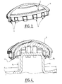
- the device illustrated in figure 1 comprises a bottle 3 of pressurized fluid provided with a protective cap 1 of a tap.
- the bottle 3 is shown schematically and partially and the valve is not shown.
- the protective cap 1 comprises a body of which a first lower end 2 is intended to be mounted on the bottle or a tap and a second upper end comprises a knob 4 for manual gripping.
- the knob 4 is for example monobloc or fixed mounted (gluing, welding, riveting, screwing ...) on the body of the cap 1.
- the cap 5 is removably attached to the knob 4.
- the cap 5 is elastically deformable and snapped onto the end of the knob 4.
- the cap 5 In the fixed position, the cap 5 is integral in translation of the knob 4 (longitudinally or laterally) but free to rotate on the latter.
- the longitudinal direction is for example the direction of the axis of the knob 4 (parallel to the bottle longitudinal axis 3 when the cap 1 is mounted on the upper end of the bottle 3).
- the knob 4 has the general shape of a mushroom that is to say a body 14 in the form of rod surmounted by a head 24 forming an outgrowth.
- the head 24 has for example the general shape of a sphere portion.
- any other geometry of knob 4 may be considered.
- the cap 5 may have the general hollow shape of the shape of the head 24 of the knob 4, for example a dome.
- the circular edge of the base of the cap 5 is provided with several elastic hooks 6 cooperating in resilient engagement with the head 24 of the knob 4.
- the hooks 6 can be oriented towards the interior of the dome so as to hook at the base of the head 24 of the knob 4. For example, four to fifteen hooks 6 can be distributed around the circumference (circular) of the cap 5 .
- the cap 5 is for example threaded so as to engage the head 24 of the knob 4 between the hooks 6 which deviate and then retract elastically when they reach the base of the head 24 of the knob 4.
- This structure allows the cap 5 to rotate relative to the fixed pommel 4. An operator can thus grip the cap 5 to rotate the bottle 3 on itself.
- the inner face of the cap and / or the outer face of the knob 4 may be shaped (shape or material) to facilitate this rotation (limited friction).
- a layer of low friction material may be provided.
- the inner face of the cap 5 may comprise ribs 7 which come into contact with the outer surface of the pommel 4 only according to point of support points and / or bearing lines.
- the base of the cap 5 has the general shape of a U or an arc of a circle, that is to say that its border has a first end forming a lateral access opening.
- the lower edge of the cap 5 has a flange 16 folded towards the inside of the cap to allow it to hook to the base of the head 24 of the knob 4.
- the first end of the cap 5 is devoid of flange 6.
- the cap 5 is introduced and threaded onto the head 24 of the knob 4 via its first end and in a direction transverse to the body 14 of the pommel.
- the opening of the first end of the cap 5 has dimensions smaller than those of the head 24 of the knob 4 so as to require an elastic deformation of the cap 5 to allow the head 24 to enter the cap 5 ( removable installation by snap-fastening).
- the cap 5 is held on the head 24 while being able to rotate around the head 24.
- the cap 5 may comprise an opening, cut or notch 8 giving access to a portion of the head 24 of the knob 4 when the cap 5 is in a fixed position on the head 24.
- This opening 8 may be provided at the first end 5 of the cap (at the opposite end of the closed end of the flange 16 closed cap 5.
- This opening 8 may allow if necessary to put a finger (for example an inch) on the knob 4 or on the visible end of the head 24, for example to prevent the head 24 of the knob 4 from inadvertently out of the cap 5 and / or to control the relative rotation between these parts.
- the cap 5 is snapped onto the end of the knob 4 with a functional clearance, for example a few millimeters.
- the cap 5 is preferably made of plastic molded or injected.
- the hat 1 has the general shape of a housing provided with lateral openings and where appropriate greater.
- the invention can be applied to any other type of hat, for example in the form of a bow or other.
- the invention makes it possible to easily and effectively equip bottle caps with a rotating knob.
Landscapes
- Engineering & Computer Science (AREA)
- Mechanical Engineering (AREA)
- General Engineering & Computer Science (AREA)
- Closures For Containers (AREA)
- Filling Or Discharging Of Gas Storage Vessels (AREA)
Applications Claiming Priority (1)
| Application Number | Priority Date | Filing Date | Title |
|---|---|---|---|
| FR1359695A FR3011611B1 (fr) | 2013-10-07 | 2013-10-07 | Chapeau de protection, capuchon et bouteille de fluide correspondants |
Publications (2)
| Publication Number | Publication Date |
|---|---|
| EP2857734A2 true EP2857734A2 (de) | 2015-04-08 |
| EP2857734A3 EP2857734A3 (de) | 2016-04-06 |
Family
ID=49753402
Family Applications (1)
| Application Number | Title | Priority Date | Filing Date |
|---|---|---|---|
| EP14183803.7A Withdrawn EP2857734A3 (de) | 2013-10-07 | 2014-09-05 | Schutzkappe, entsprechende Kappe und entsprechende Flüssigkeitsflasche |
Country Status (2)
| Country | Link |
|---|---|
| EP (1) | EP2857734A3 (de) |
| FR (1) | FR3011611B1 (de) |
Cited By (2)
| Publication number | Priority date | Publication date | Assignee | Title |
|---|---|---|---|---|
| US20150083237A1 (en) * | 2012-04-19 | 2015-03-26 | L'Air Liquide, Société Anonyme pour I'Etude Exploitation des Procétdés George Claude | Protective cap for a pressurised fluid cylinder valve and production method thereof |
| US20220099254A1 (en) * | 2020-09-25 | 2022-03-31 | Richard Bradley TAVES | Gas cylinder mobility aid |
Citations (5)
| Publication number | Priority date | Publication date | Assignee | Title |
|---|---|---|---|---|
| FR2803366A1 (fr) | 2000-01-05 | 2001-07-06 | Air Liquide | Bouteille de gaz equipee d'un capotage a pommeau mobile et/ ou rotatif |
| DE10057425A1 (de) | 2000-11-20 | 2002-05-29 | Messer Griesheim Gmbh | Griffelement mit Knauf für Schutzkappen von Druckgasbehältern |
| WO2007012524A1 (de) | 2005-07-27 | 2007-02-01 | Vdo Automotive Ag | Getriebe für ein bremssystem und bremssystem |
| FR2976047A1 (fr) | 2011-05-31 | 2012-12-07 | Air Liquide | Chapeau de protection pour robinet de bouteille de fluide sous pression |
| FR2976046A1 (fr) | 2011-05-31 | 2012-12-07 | Air Liquide | Chapeau de protection pour robinet de bouteille de fluide sous pression |
-
2013
- 2013-10-07 FR FR1359695A patent/FR3011611B1/fr not_active Expired - Fee Related
-
2014
- 2014-09-05 EP EP14183803.7A patent/EP2857734A3/de not_active Withdrawn
Patent Citations (5)
| Publication number | Priority date | Publication date | Assignee | Title |
|---|---|---|---|---|
| FR2803366A1 (fr) | 2000-01-05 | 2001-07-06 | Air Liquide | Bouteille de gaz equipee d'un capotage a pommeau mobile et/ ou rotatif |
| DE10057425A1 (de) | 2000-11-20 | 2002-05-29 | Messer Griesheim Gmbh | Griffelement mit Knauf für Schutzkappen von Druckgasbehältern |
| WO2007012524A1 (de) | 2005-07-27 | 2007-02-01 | Vdo Automotive Ag | Getriebe für ein bremssystem und bremssystem |
| FR2976047A1 (fr) | 2011-05-31 | 2012-12-07 | Air Liquide | Chapeau de protection pour robinet de bouteille de fluide sous pression |
| FR2976046A1 (fr) | 2011-05-31 | 2012-12-07 | Air Liquide | Chapeau de protection pour robinet de bouteille de fluide sous pression |
Cited By (4)
| Publication number | Priority date | Publication date | Assignee | Title |
|---|---|---|---|---|
| US20150083237A1 (en) * | 2012-04-19 | 2015-03-26 | L'Air Liquide, Société Anonyme pour I'Etude Exploitation des Procétdés George Claude | Protective cap for a pressurised fluid cylinder valve and production method thereof |
| US20150107695A1 (en) * | 2012-04-19 | 2015-04-23 | L'Air Liquide, Société Anonyme pour l'Etude de l'Exploitation des Procédé Georges Claude | Protective cap for a pressurised fluid cylinder valve and production method thereof |
| US20220099254A1 (en) * | 2020-09-25 | 2022-03-31 | Richard Bradley TAVES | Gas cylinder mobility aid |
| US11512814B2 (en) * | 2020-09-25 | 2022-11-29 | Richard Bradley TAVES | Gas cylinder mobility aid |
Also Published As
| Publication number | Publication date |
|---|---|
| FR3011611A1 (fr) | 2015-04-10 |
| EP2857734A3 (de) | 2016-04-06 |
| FR3011611B1 (fr) | 2016-02-26 |
Similar Documents
| Publication | Publication Date | Title |
|---|---|---|
| EP0729719B9 (de) | Vorrichtung zum Auftragen eines pastösen Produktes, insbesondere eines kosmetischen Produktes wie Lippenstift | |
| EP3088970B1 (de) | Armbanduhr, die zum befestigen auf einer entfernbaren halterung konzipiert ist | |
| FR2466405A1 (fr) | Dispositif de stockage de produits tels que semences ou analogues comprenant un reservoir cryobiologique | |
| FR2675081A1 (fr) | Dispositif de montage de roues a nez sur un axe de roue. | |
| FR2866324A1 (fr) | Recipient destine a conserver des boissons | |
| EP2857734A2 (de) | Schutzkappe, entsprechende Kappe und entsprechende Flüssigkeitsflasche | |
| EP0953513B1 (de) | Verpackung aus Metall mit Sicherheitskappe | |
| EP2162623B1 (de) | Kupplungsteil zur befestigung und entnahme eines abnehmbaren zubehörteils in zusammenhang mit einer stationären trägerstruktur | |
| EP2958816A1 (de) | Verfahren zum schutz eines behälters und auf diese weise geschützter behälter | |
| FR3075764B1 (fr) | Bouteille munie d'un dispositif de verrouillage dans le bouchon | |
| EP2715207B1 (de) | Schutzkappe für ein druckflüssigkeitszylinderventil | |
| FR3016425A1 (fr) | Chapeau de protection et bouteille de fluide comprenant un tel chapeau | |
| FR3031089A1 (fr) | Enveloppe rigide pour tube compressible | |
| FR3144769A1 (fr) | Couteau à lame articulée muni d’un décapsuleur | |
| EP2409928B1 (de) | Mit einem Clip verschließbarer Verschlussstopfen | |
| EP1488856B1 (de) | Mit einem Druckknopf versehene Vorrichtung zur Verpackung und Abgabe | |
| WO2010046566A1 (fr) | Bouchon a obturateur coulissant | |
| FR2664947A1 (fr) | Systeme de fixation demontable d'un element par rapport a un organe fixe, ledit element etant notamment un enjoliveur de roue de vehicule. | |
| EP4436719B1 (de) | Öffungs-/schliess- und sprüh-vorrichtung für eine flasche, z.b. für eine parfümflasche, sowie eine solche flasche | |
| FR2753950A1 (fr) | Support-papier pour tube de poignee de chariot de transport ou manutention, et tube de poignee et chariot equipes d'un tel support-papier | |
| FR3064898A1 (fr) | Ensemble pour un dispositif de conditionnement de produit cosmetique comportant un support et un bloc de produit cosmetique et un tel support de produit cosmetique | |
| FR3125386A1 (fr) | Dispositif et procédé de support et de retenue d’un tissu. | |
| FR3000010A1 (fr) | Ensemble de fixation de roue de secours dans un vehicule automobile | |
| FR2678242A1 (fr) | Capot pour le coiffage de recipients tels que des atomiseurs ou des vaporisateurs. | |
| EP2612641A1 (de) | Positionshaltevorrichtung eines Stocks in umgekehrter, im Wesentlichen vertikaler Position |
Legal Events
| Date | Code | Title | Description |
|---|---|---|---|
| PUAI | Public reference made under article 153(3) epc to a published international application that has entered the european phase |
Free format text: ORIGINAL CODE: 0009012 |
|
| 17P | Request for examination filed |
Effective date: 20140905 |
|
| AK | Designated contracting states |
Kind code of ref document: A2 Designated state(s): AL AT BE BG CH CY CZ DE DK EE ES FI FR GB GR HR HU IE IS IT LI LT LU LV MC MK MT NL NO PL PT RO RS SE SI SK SM TR |
|
| AX | Request for extension of the european patent |
Extension state: BA ME |
|
| PUAL | Search report despatched |
Free format text: ORIGINAL CODE: 0009013 |
|
| AK | Designated contracting states |
Kind code of ref document: A3 Designated state(s): AL AT BE BG CH CY CZ DE DK EE ES FI FR GB GR HR HU IE IS IT LI LT LU LV MC MK MT NL NO PL PT RO RS SE SI SK SM TR |
|
| AX | Request for extension of the european patent |
Extension state: BA ME |
|
| RIC1 | Information provided on ipc code assigned before grant |
Ipc: F17C 1/00 20060101AFI20160229BHEP |
|
| R17P | Request for examination filed (corrected) |
Effective date: 20161006 |
|
| RBV | Designated contracting states (corrected) |
Designated state(s): AL AT BE BG CH CY CZ DE DK EE ES FI FR GB GR HR HU IE IS IT LI LT LU LV MC MK MT NL NO PL PT RO RS SE SI SK SM TR |
|
| GRAP | Despatch of communication of intention to grant a patent |
Free format text: ORIGINAL CODE: EPIDOSNIGR1 |
|
| STAA | Information on the status of an ep patent application or granted ep patent |
Free format text: STATUS: THE APPLICATION HAS BEEN WITHDRAWN |
|
| INTG | Intention to grant announced |
Effective date: 20190520 |
|
| 18W | Application withdrawn |
Effective date: 20190527 |