EP2857230A1 - Verstellbarer Reifendruckdetektor - Google Patents
Verstellbarer Reifendruckdetektor Download PDFInfo
- Publication number
- EP2857230A1 EP2857230A1 EP13187512.2A EP13187512A EP2857230A1 EP 2857230 A1 EP2857230 A1 EP 2857230A1 EP 13187512 A EP13187512 A EP 13187512A EP 2857230 A1 EP2857230 A1 EP 2857230A1
- Authority
- EP
- European Patent Office
- Prior art keywords
- assembly
- gas
- hole
- section
- tire pressure
- Prior art date
- Legal status (The legal status is an assumption and is not a legal conclusion. Google has not performed a legal analysis and makes no representation as to the accuracy of the status listed.)
- Granted
Links
- 238000003825 pressing Methods 0.000 claims abstract description 7
- 230000008878 coupling Effects 0.000 claims description 37
- 238000010168 coupling process Methods 0.000 claims description 37
- 238000005859 coupling reaction Methods 0.000 claims description 37
- 238000009434 installation Methods 0.000 claims description 16
- 230000000149 penetrating effect Effects 0.000 claims description 6
- 239000011324 bead Substances 0.000 claims description 4
- 238000000034 method Methods 0.000 description 4
- 230000005856 abnormality Effects 0.000 description 1
- 230000005540 biological transmission Effects 0.000 description 1
- 230000000295 complement effect Effects 0.000 description 1
- 230000007774 longterm Effects 0.000 description 1
- 238000004519 manufacturing process Methods 0.000 description 1
- 238000012986 modification Methods 0.000 description 1
- 230000004048 modification Effects 0.000 description 1
- 238000005086 pumping Methods 0.000 description 1
Images


Classifications
-
- B—PERFORMING OPERATIONS; TRANSPORTING
- B60—VEHICLES IN GENERAL
- B60C—VEHICLE TYRES; TYRE INFLATION; TYRE CHANGING; CONNECTING VALVES TO INFLATABLE ELASTIC BODIES IN GENERAL; DEVICES OR ARRANGEMENTS RELATED TO TYRES
- B60C23/00—Devices for measuring, signalling, controlling, or distributing tyre pressure or temperature, specially adapted for mounting on vehicles; Arrangement of tyre inflating devices on vehicles, e.g. of pumps or of tanks; Tyre cooling arrangements
- B60C23/02—Signalling devices actuated by tyre pressure
- B60C23/04—Signalling devices actuated by tyre pressure mounted on the wheel or tyre
- B60C23/0408—Signalling devices actuated by tyre pressure mounted on the wheel or tyre transmitting the signals by non-mechanical means from the wheel or tyre to a vehicle body mounted receiver
- B60C23/0422—Signalling devices actuated by tyre pressure mounted on the wheel or tyre transmitting the signals by non-mechanical means from the wheel or tyre to a vehicle body mounted receiver characterised by the type of signal transmission means
- B60C23/0433—Radio signals
- B60C23/0447—Wheel or tyre mounted circuits
- B60C23/0452—Antenna structure, control or arrangement
-
- B—PERFORMING OPERATIONS; TRANSPORTING
- B60—VEHICLES IN GENERAL
- B60C—VEHICLE TYRES; TYRE INFLATION; TYRE CHANGING; CONNECTING VALVES TO INFLATABLE ELASTIC BODIES IN GENERAL; DEVICES OR ARRANGEMENTS RELATED TO TYRES
- B60C23/00—Devices for measuring, signalling, controlling, or distributing tyre pressure or temperature, specially adapted for mounting on vehicles; Arrangement of tyre inflating devices on vehicles, e.g. of pumps or of tanks; Tyre cooling arrangements
- B60C23/02—Signalling devices actuated by tyre pressure
- B60C23/04—Signalling devices actuated by tyre pressure mounted on the wheel or tyre
- B60C23/0491—Constructional details of means for attaching the control device
- B60C23/0494—Valve stem attachments positioned inside the tyre chamber
Definitions
- the present invention relates to an adjustable tire pressure detector, and particularly to an adjustable tire pressure detector adapted to various types of tire rims.
- a tire pressure sensor disposed on a tire rim of a vehicle, constantly monitors the gas pressure and temperature of the tire, and outputs sensed values to a vehicle display device or a vehicle status warning device through wireless transmission. As such, a driver of the vehicle may be informed of the tire pressure status in real-time during a driving process, so as to prevent accidents resulted by tire abnormalities.
- a tire sensor is usually connected to a gas intake nozzle disposed on an assembly hole of the tire rim.
- the gas intake nozzle serves as an input end for a user to pump gas into the tire.
- manufacturer needs to perform structural adjustments to the tire pressure sensor for each vehicle model or each uniquely designed tire rim individually. Consequently, production costs are increased.
- a tire pressure sensor capable of appropriately adjusting according to the shape of a tire rim is proposed. For example, as a tire pressure sensor disclosed in the Taiwan Utility Model No. M405977 , a gas intake nozzle thereof is disposed with an arched outer adjustment surface.
- the tire pressure sensor is further disposed with an arched inner adjustment surface at a position connecting to the gas intake nozzle.
- the outer adjustment surface and the inner adjustment surface are complementary in shape to perform relative sliding movements.
- the gas intake nozzle is fastened on the tire pressure sensor by penetrating a screw bolt through the outer adjustment surface of the gas intake nozzle and the inner adjustment surface of the tire pressure sensor.
- tire pressure sensor becomes suitable for any desired tire rim.
- the gas intake nozzle is able to slide relatively to the tire pressure sensor and the two are fastened merely by one single screw bolt, jittering during a driving process may cause the gas intake nozzle to waver relatively to the tire pressure sensor. Under a long-term use, the gas intake nozzle is prone to loosening or even disengagement from the tire pressure sensor.
- the primary object of the present invention is to provide an adjustable tire pressure detector that can be installed on different types of tire rims.
- an adjustable tire pressure detector is provided according to an embodiment of the present invention.
- the adjustable tire pressure detector is installed on a tire rim.
- the tire rim includes two fastening sections at two sides to engage with a tire bead of a tire, a connecting section connecting the two fastening sections, and an assembly through hole disposed at one of the fastening sections.
- the adjustable tire pressure detector includes a detector body, a gas intake nozzle, and a gas nozzle assembly member.
- the detector body is disposed at the fastening sections and includes a housing and a gas nozzle assembly hole penetrating through the housing.
- the gas nozzle assembly hole includes two parallel limiting contact surfaces and at least one connecting surface connecting the two limiting contact surfaces.
- the gas intake nozzle includes a coupling section inserted into the gas nozzle assembly hole, and a gas intake section extending from the coupling section towards the assembly through hole.
- the coupling section includes two compact surfaces corresponding to and tightly pressing against the limiting contact surfaces, at least one abutting contact surface connecting the two compact surfaces and contacting with the connecting surface, and an assembly hole facing the gas nozzle assembly hole. A distance between the two compact surfaces gradually increases from the coupling section towards the gas intake section.
- the gas nozzle assembly member penetrates through the gas nozzle assembly hole to couple with the assembly hole of the gas intake nozzle, so as to fasten the gas intake nozzle onto the detector body.
- the detector body includes at least one support section extending towards the connection section. Further, the support section includes a buffer member abutting against the connecting section.
- the gas nozzle assembly member further includes an outer screw thread
- the assembly hole includes an inner screw thread for screwing with the outer screw thread
- the gas intake nozzle includes a limiting fixing section disposed between the coupling section and the gas intake section to engage with the assembly through hole.
- the detector body includes an installation sleeve disposed between gas nozzle assembly hole and the coupling section of the gas intake nozzle.
- the installation sleeve allows the gas intake nozzle to perform an adjustment movement after being assembled.
- the installation sleeve includes an assembly end, and the detector body includes an installation portion to couple with the assembly end.
- the adjustable tire pressure detector of the present invention offers the features below:
- the adjustable tire pressure detector includes a detector body, a gas intake nozzle, and a gas nozzle assembly member.
- the detector body is disposed at the fastening sections, and includes a housing and a gas nozzle assembly hole formed on the housing.
- the gas nozzle assembly hole includes two parallel limiting contact surfaces; an assembly surface connecting the two limiting contact surfaces, and including an opening facing the assembly through hole; and an assembly space surrounded by the two limiting contact surfaces and the assembly surface.
- the gas intake nozzle includes a coupling section inserted into the assembly space, and a gas intake section extending from the coupling section towards the assembly through hole.
- the coupling section includes two parallel compact surfaces corresponding to and tightly pressing against the limiting contact surfaces; and an arched assembly surface connecting the two parallel compact surfaces, including an assembly hole corresponding to the opening, and being in line contact with the assembly surface.
- the gas nozzle assembly member penetrates through the opening to couple with the assembly hole of the gas intake nozzle, so as to fasten the gas intake nozzle onto the detector body.
- the detector body includes at least one support section extending towards the connection section.
- the gas nozzle assembly member further includes an outer screw thread
- the assembly hole includes an inner screw thread for screwing with the outer screw thread
- the gas intake nozzle further includes a limiting fixing section disposed between the coupling section and the gas intake section to engage with the assembly through hole.
- the gas intake nozzle further includes a gas outlet through hole interconnected with the assembly hole to allow an inflation gas to enter the tire.
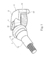
- an adjustable tire pressure detector of the present invention is installed on a tire rim 11.
- the tire rim 11 includes two fastening sections 111 at two sides to engage with a tire bead of a tire (not shown), a connecting section 112 connecting the two fastening sections 111, and an assembly through hole 113 disposed at one of the fastening sections 111.
- the adjustable tire pressure detector includes a detector body 2, a gas intake nozzle 3, and a gas nozzle assembly member 4.
- the detector body 2 includes a housing 21 and a gas nozzle assembly hole 22 penetrating through the housing 21.
- the gas nozzle assembly hole 22 which appears an ellipse shape, includes two parallel limiting contact surfaces 221 and at least one connecting surface 222 connecting the two limiting contact surfaces 221.
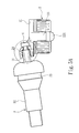
- the gas intake nozzle 3 includes a coupling section 31 inserted into the gas nozzle assembly hole 22, and a gas intake section 32 extending from the coupling section 31 towards the assembly through hole 113.
- the coupling section 31 includes two compact surfaces 311 corresponding to and tightly pressing against the limiting contact surfaces 221, at least one abutting contact surface 312 connecting the two compact surfaces 311 and contacting with the connecting surface 222, and an assembly hole 313 facing the gas nozzle assembly hole 22. A distance between the two compact surfaces 311 gradually increases from the coupling section 31 towards the gas intake section 32.
- each of the compact surfaces 311 is formed at a width smaller than that of the limiting contact surface 221, such that an appropriate adjustment can be performed according to a size of the tire rim 11 after inserting the coupling section 31 into the gas nozzle assembly hole 22.
- the gas nozzle assembly member 4 penetrates through the gas nozzle assembly hole 22 and then couples with the assembly hole 313 of the gas intake nozzle 3, so as to fasten the gas intake nozzle 3 onto the detector body 2.
- the detector body 2 further includes a support section 23 extending towards the connecting section 112 to separate the detector body 2 from the tire rim 11 by a distance.
- the support section 23 includes a buffer member 231 abutting against the connecting section 112.
- the buffer member 231 is disposed to alleviate the jittering of the tire rim 11 which may damage of the detector body 2 during a driving process.
- the gas intake nozzle 3 includes a limiting fixing section 33 and a gas outlet through hole.
- the limiting fixing section 33 is disposed between the coupling section 31 and the gas intake section 32 to engage with the assembly through hole 113.
- the gas outlet through hole is interconnected with the assembly hole 313 and allows pumping gas to enter the tire.
- the gas nozzle assembly member 4 further includes an outer screw thread 41
- the assembly hole 313 includes an inner screw thread 314 for screwing with the outer screw thread 41.
- the detector body 2 further includes an installation sleeve 24 disposed between gas nozzle assembly hole 22 and the coupling section 31 of the gas intake nozzle 3.
- the installation sleeve 24 allows the gas intake nozzle 3 to perform an adjustment movement after being assembled.
- the installation sleeve 24 appears similar to a taper shape, such that only an end portion of the coupling section 31 comes into contact with the installation sleeve 24 after inserting the coupling section 31 into the installation sleeve 24.
- the gas intake nozzle 3 when installing the gas intake nozzle 3 on the tire rim 11, the gas intake nozzle 3 is not inserted into the gas nozzle assembly hole 22 by a fixed angle. More specifically, the above-mentioned adjustment movement refers to a process that, through the installation sleeve 24, the coupling section 31 of the gas intake nozzle 3 is allowed to move appropriately in the gas nozzle assembly hole 22, such as moving up or down, or swinging up or down, to adjust to a preferred assembly position.
- the installation sleeve 24 further includes an assembly end 241, and the detector body 2 further includes an installation portion 211 to couple with the assembly end 241.
- the installation portion 211 may be a through hole.
- the gas intake nozzle 3 is disassembled into the coupling section 31 and the gas intake section 32.
- the gas intake section 32 is disposed from an outer side of the tire rim 11 towards an inner side of the tire rim 11, and the coupling section 31 is disposed from the inner side of the tire rim 11 towards the outer side of the tire rim 11, so as to couple the coupling section 31 with the gas intake section 32 from two sides of the assembly through hole 113 and thus fasten the gas intake nozzle 3 onto the tire rim 11.
- the coupling section 31 is inserted into the gas nozzle assembly hole 22 of the detector body 2, and an assembly angle of the coupling section 31 is adjusted according to a shape of the tire rim 11.
- the abutting contact surface 312 comes into contact with only one of the connecting surfaces 222, and the compact surfaces 311 is limited and oppressed by the limiting contact surface 221, so as to assemble the gas intake nozzle 3 onto the detector body 2.
- the coupling section 31 is allowed to adjust an assembly angle thereof in the gas nozzle assembly hole 22 to adapt to different type of tire rims 11.
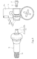
- FIG. 6 shows another embodiment of the present invention.
- a gas nozzle assembly hole 22a on a detector body 2a includes two parallel limiting contact surfaces 221a; an assembly surface 223a connecting the two limiting contact surfaces 221a and including an opening 224a facing the assembly through hole 113; and an assembly space 225a surrounded by the two limiting contact surfaces 221a and the assembly surface 223a.
- a coupling section 31a of a gas intake nozzle 3a includes two parallel compact surfaces 311a corresponding to and tightly pressing against the limiting contact surfaces 221a; and an arched assembly surface 315a connecting the two parallel compact surfaces 311a, including an assembly hole 313a corresponding to the opening 224a, and being in line contact with the assembly surface 223a.
- an angle at which the gas intake nozzle 3a enters the assembly space 225a may be adjusted. That is, a position at which the arched assembly surface 315a comes into contact with the assembly surface 223a is adjustable, so as to allow the gas inlet nozzle 3a to move in the assembly space 225a to adjust to a preferred assembly angle.
- the size of the gas intake nozzle 3 a may be smaller than that of the assembly space 225a, so that the gas intake nozzle 3a may be levelly moved to be adjusted to an appropriate assembly position during assembling.
- an adjustable tire pressure detector of the present invention installed to a tire rim, includes a detector body, a gas intake nozzle and a gas nozzle assembly member.
- the detector body includes a housing and a gas nozzle assembly hole.
- the gas nozzle assembly hole has two parallel limiting contact surfaces, and at least one contact surface connecting the two limiting contact surfaces.
- the gas intake nozzle includes two compact surfaces respectively corresponding to the limiting contact surfaces to closely pack against the limiting contact surfaces, at least one abutting contact surface connecting the two compact surfaces and contacting with the connecting surface, and an assembly hole facing the gas nozzle assembly hole.
- the gas nozzle assembly member is assembled to the assembly hole of the gas intake nozzle to fasten the gas intake nozzle onto the detector body.
- the adjustable tire pressure detector of the present invention may be installed to tire rims of different sizes.
Landscapes
- Engineering & Computer Science (AREA)
- Mechanical Engineering (AREA)
- Measuring Fluid Pressure (AREA)
Priority Applications (1)
| Application Number | Priority Date | Filing Date | Title |
|---|---|---|---|
| EP13187512.2A EP2857230B1 (de) | 2013-10-07 | 2013-10-07 | Verstellbarer Reifendruckdetektor |
Applications Claiming Priority (1)
| Application Number | Priority Date | Filing Date | Title |
|---|---|---|---|
| EP13187512.2A EP2857230B1 (de) | 2013-10-07 | 2013-10-07 | Verstellbarer Reifendruckdetektor |
Publications (2)
| Publication Number | Publication Date |
|---|---|
| EP2857230A1 true EP2857230A1 (de) | 2015-04-08 |
| EP2857230B1 EP2857230B1 (de) | 2016-06-08 |
Family
ID=49326548
Family Applications (1)
| Application Number | Title | Priority Date | Filing Date |
|---|---|---|---|
| EP13187512.2A Not-in-force EP2857230B1 (de) | 2013-10-07 | 2013-10-07 | Verstellbarer Reifendruckdetektor |
Country Status (1)
| Country | Link |
|---|---|
| EP (1) | EP2857230B1 (de) |
Cited By (1)
| Publication number | Priority date | Publication date | Assignee | Title |
|---|---|---|---|---|
| US11338631B2 (en) * | 2017-10-16 | 2022-05-24 | Continental Automotive France | Inflation valve for tire rim with limitation of elastic deformation |
Families Citing this family (1)
| Publication number | Priority date | Publication date | Assignee | Title |
|---|---|---|---|---|
| US11760138B2 (en) * | 2021-09-23 | 2023-09-19 | Wonder S.P.A. | Tire inflation valve equipped with adjusting system for a TPMS sensor |
Citations (6)
| Publication number | Priority date | Publication date | Assignee | Title |
|---|---|---|---|---|
| DE202007009443U1 (de) * | 2006-12-04 | 2007-09-13 | Shanghai Baolong Industries Corporation, Dongjing | Signalgehäuseeinheit für einen stufenweise einstellbaren Reifendrucksensor |
| US20080074251A1 (en) * | 2006-01-23 | 2008-03-27 | Emmanuel Marguet | Tire monitor system having tire valve antenna |
| CN201376472Y (zh) * | 2008-12-17 | 2010-01-06 | 翔鑫科技股份有限公司 | 胎压侦测器的结构改良 |
| TWM405977U (en) | 2011-01-19 | 2011-06-21 | Cub Elecparts Inc | Tire pressure sensor and air nozzle assembly |
| US20130009762A1 (en) * | 2011-07-06 | 2013-01-10 | San-Chuan Yu | Tire pressure sensor and nozzle assembly |
| FR2983781A1 (fr) * | 2011-12-12 | 2013-06-14 | Schrader | Valve asymetrique pour roue de vehicule associee a un boitier capteur de pression par des moyens d'indexation reciproques |
-
2013
- 2013-10-07 EP EP13187512.2A patent/EP2857230B1/de not_active Not-in-force
Patent Citations (6)
| Publication number | Priority date | Publication date | Assignee | Title |
|---|---|---|---|---|
| US20080074251A1 (en) * | 2006-01-23 | 2008-03-27 | Emmanuel Marguet | Tire monitor system having tire valve antenna |
| DE202007009443U1 (de) * | 2006-12-04 | 2007-09-13 | Shanghai Baolong Industries Corporation, Dongjing | Signalgehäuseeinheit für einen stufenweise einstellbaren Reifendrucksensor |
| CN201376472Y (zh) * | 2008-12-17 | 2010-01-06 | 翔鑫科技股份有限公司 | 胎压侦测器的结构改良 |
| TWM405977U (en) | 2011-01-19 | 2011-06-21 | Cub Elecparts Inc | Tire pressure sensor and air nozzle assembly |
| US20130009762A1 (en) * | 2011-07-06 | 2013-01-10 | San-Chuan Yu | Tire pressure sensor and nozzle assembly |
| FR2983781A1 (fr) * | 2011-12-12 | 2013-06-14 | Schrader | Valve asymetrique pour roue de vehicule associee a un boitier capteur de pression par des moyens d'indexation reciproques |
Cited By (1)
| Publication number | Priority date | Publication date | Assignee | Title |
|---|---|---|---|---|
| US11338631B2 (en) * | 2017-10-16 | 2022-05-24 | Continental Automotive France | Inflation valve for tire rim with limitation of elastic deformation |
Also Published As
| Publication number | Publication date |
|---|---|
| EP2857230B1 (de) | 2016-06-08 |
Similar Documents
| Publication | Publication Date | Title |
|---|---|---|
| US9315079B2 (en) | Adjustable tire pressure detector | |
| US9475350B2 (en) | Tire pressure measurement apparatus | |
| US9238389B2 (en) | Adjustable tire pressure detector | |
| CN104903599B (zh) | 适合拧的索环连接组件 | |
| EP3284957B1 (de) | Werkzeug zur sensorbefestigung | |
| US8539826B2 (en) | Pressure sensor and nozzle assembly | |
| US8585336B2 (en) | Fastener | |
| CA2455458A1 (en) | System and technique for mounting a faucet | |
| US10288201B2 (en) | Hose line and method for producing a hose line | |
| EP2857230A1 (de) | Verstellbarer Reifendruckdetektor | |
| US11408157B2 (en) | Fixture pod for a lavatory fixture | |
| US20180186201A1 (en) | Auxiliary Fixture for a Tire Pressure Monitoring Device | |
| KR101470758B1 (ko) | 조절 가능한 타이어 압력 탐지기 | |
| JP5841573B2 (ja) | 調整式タイヤ空気圧センサ | |
| US20150183098A1 (en) | Torque tire arbor | |
| CN204568361U (zh) | 冷媒连接管的封口塞 | |
| US20090245926A1 (en) | Quick Connector for Portable Power Tools | |
| CN109424837A (zh) | 壁挂结构 | |
| CN104712639A (zh) | 一种用于空气滤清器的锁紧卡扣机构 | |
| CN208216431U (zh) | 一种安装角度可调式胎压监测传感器 | |
| EP3650248A1 (de) | Reifendrucksensorvorrichtung | |
| JP3187036U (ja) | クランプリング | |
| CN221497887U (zh) | 一种车载摄像头的固定结构及车载摄像头 | |
| CN201672857U (zh) | 气枪 | |
| JP4993787B2 (ja) | 取付け角度調整型ワッシャー |
Legal Events
| Date | Code | Title | Description |
|---|---|---|---|
| PUAI | Public reference made under article 153(3) epc to a published international application that has entered the european phase |
Free format text: ORIGINAL CODE: 0009012 |
|
| 17P | Request for examination filed |
Effective date: 20140513 |
|
| AK | Designated contracting states |
Kind code of ref document: A1 Designated state(s): AL AT BE BG CH CY CZ DE DK EE ES FI FR GB GR HR HU IE IS IT LI LT LU LV MC MK MT NL NO PL PT RO RS SE SI SK SM TR |
|
| AX | Request for extension of the european patent |
Extension state: BA ME |
|
| 17Q | First examination report despatched |
Effective date: 20150803 |
|
| GRAP | Despatch of communication of intention to grant a patent |
Free format text: ORIGINAL CODE: EPIDOSNIGR1 |
|
| INTG | Intention to grant announced |
Effective date: 20160209 |
|
| GRAS | Grant fee paid |
Free format text: ORIGINAL CODE: EPIDOSNIGR3 |
|
| GRAA | (expected) grant |
Free format text: ORIGINAL CODE: 0009210 |
|
| AK | Designated contracting states |
Kind code of ref document: B1 Designated state(s): AL AT BE BG CH CY CZ DE DK EE ES FI FR GB GR HR HU IE IS IT LI LT LU LV MC MK MT NL NO PL PT RO RS SE SI SK SM TR |
|
| REG | Reference to a national code |
Ref country code: GB Ref legal event code: FG4D |
|
| REG | Reference to a national code |
Ref country code: CH Ref legal event code: EP |
|
| REG | Reference to a national code |
Ref country code: IE Ref legal event code: FG4D |
|
| REG | Reference to a national code |
Ref country code: AT Ref legal event code: REF Ref document number: 804946 Country of ref document: AT Kind code of ref document: T Effective date: 20160715 |
|
| REG | Reference to a national code |
Ref country code: DE Ref legal event code: R096 Ref document number: 602013008340 Country of ref document: DE |
|
| REG | Reference to a national code |
Ref country code: NL Ref legal event code: FP |
|
| REG | Reference to a national code |
Ref country code: LT Ref legal event code: MG4D |
|
| REG | Reference to a national code |
Ref country code: FR Ref legal event code: PLFP Year of fee payment: 4 |
|
| PG25 | Lapsed in a contracting state [announced via postgrant information from national office to epo] |
Ref country code: NO Free format text: LAPSE BECAUSE OF FAILURE TO SUBMIT A TRANSLATION OF THE DESCRIPTION OR TO PAY THE FEE WITHIN THE PRESCRIBED TIME-LIMIT Effective date: 20160908 Ref country code: LT Free format text: LAPSE BECAUSE OF FAILURE TO SUBMIT A TRANSLATION OF THE DESCRIPTION OR TO PAY THE FEE WITHIN THE PRESCRIBED TIME-LIMIT Effective date: 20160608 Ref country code: FI Free format text: LAPSE BECAUSE OF FAILURE TO SUBMIT A TRANSLATION OF THE DESCRIPTION OR TO PAY THE FEE WITHIN THE PRESCRIBED TIME-LIMIT Effective date: 20160608 |
|
| REG | Reference to a national code |
Ref country code: AT Ref legal event code: MK05 Ref document number: 804946 Country of ref document: AT Kind code of ref document: T Effective date: 20160608 |
|
| PG25 | Lapsed in a contracting state [announced via postgrant information from national office to epo] |
Ref country code: LV Free format text: LAPSE BECAUSE OF FAILURE TO SUBMIT A TRANSLATION OF THE DESCRIPTION OR TO PAY THE FEE WITHIN THE PRESCRIBED TIME-LIMIT Effective date: 20160608 Ref country code: RS Free format text: LAPSE BECAUSE OF FAILURE TO SUBMIT A TRANSLATION OF THE DESCRIPTION OR TO PAY THE FEE WITHIN THE PRESCRIBED TIME-LIMIT Effective date: 20160608 Ref country code: ES Free format text: LAPSE BECAUSE OF FAILURE TO SUBMIT A TRANSLATION OF THE DESCRIPTION OR TO PAY THE FEE WITHIN THE PRESCRIBED TIME-LIMIT Effective date: 20160608 Ref country code: HR Free format text: LAPSE BECAUSE OF FAILURE TO SUBMIT A TRANSLATION OF THE DESCRIPTION OR TO PAY THE FEE WITHIN THE PRESCRIBED TIME-LIMIT Effective date: 20160608 Ref country code: SE Free format text: LAPSE BECAUSE OF FAILURE TO SUBMIT A TRANSLATION OF THE DESCRIPTION OR TO PAY THE FEE WITHIN THE PRESCRIBED TIME-LIMIT Effective date: 20160608 Ref country code: GR Free format text: LAPSE BECAUSE OF FAILURE TO SUBMIT A TRANSLATION OF THE DESCRIPTION OR TO PAY THE FEE WITHIN THE PRESCRIBED TIME-LIMIT Effective date: 20160909 |
|
| PG25 | Lapsed in a contracting state [announced via postgrant information from national office to epo] |
Ref country code: EE Free format text: LAPSE BECAUSE OF FAILURE TO SUBMIT A TRANSLATION OF THE DESCRIPTION OR TO PAY THE FEE WITHIN THE PRESCRIBED TIME-LIMIT Effective date: 20160608 Ref country code: SK Free format text: LAPSE BECAUSE OF FAILURE TO SUBMIT A TRANSLATION OF THE DESCRIPTION OR TO PAY THE FEE WITHIN THE PRESCRIBED TIME-LIMIT Effective date: 20160608 Ref country code: IS Free format text: LAPSE BECAUSE OF FAILURE TO SUBMIT A TRANSLATION OF THE DESCRIPTION OR TO PAY THE FEE WITHIN THE PRESCRIBED TIME-LIMIT Effective date: 20161008 Ref country code: RO Free format text: LAPSE BECAUSE OF FAILURE TO SUBMIT A TRANSLATION OF THE DESCRIPTION OR TO PAY THE FEE WITHIN THE PRESCRIBED TIME-LIMIT Effective date: 20160608 |
|
| PG25 | Lapsed in a contracting state [announced via postgrant information from national office to epo] |
Ref country code: AT Free format text: LAPSE BECAUSE OF FAILURE TO SUBMIT A TRANSLATION OF THE DESCRIPTION OR TO PAY THE FEE WITHIN THE PRESCRIBED TIME-LIMIT Effective date: 20160608 Ref country code: SM Free format text: LAPSE BECAUSE OF FAILURE TO SUBMIT A TRANSLATION OF THE DESCRIPTION OR TO PAY THE FEE WITHIN THE PRESCRIBED TIME-LIMIT Effective date: 20160608 Ref country code: PT Free format text: LAPSE BECAUSE OF FAILURE TO SUBMIT A TRANSLATION OF THE DESCRIPTION OR TO PAY THE FEE WITHIN THE PRESCRIBED TIME-LIMIT Effective date: 20161010 Ref country code: PL Free format text: LAPSE BECAUSE OF FAILURE TO SUBMIT A TRANSLATION OF THE DESCRIPTION OR TO PAY THE FEE WITHIN THE PRESCRIBED TIME-LIMIT Effective date: 20160608 Ref country code: BE Free format text: LAPSE BECAUSE OF NON-PAYMENT OF DUE FEES Effective date: 20160608 |
|
| REG | Reference to a national code |
Ref country code: DE Ref legal event code: R097 Ref document number: 602013008340 Country of ref document: DE |
|
| PLBE | No opposition filed within time limit |
Free format text: ORIGINAL CODE: 0009261 |
|
| STAA | Information on the status of an ep patent application or granted ep patent |
Free format text: STATUS: NO OPPOSITION FILED WITHIN TIME LIMIT |
|
| 26N | No opposition filed |
Effective date: 20170309 |
|
| PG25 | Lapsed in a contracting state [announced via postgrant information from national office to epo] |
Ref country code: DK Free format text: LAPSE BECAUSE OF FAILURE TO SUBMIT A TRANSLATION OF THE DESCRIPTION OR TO PAY THE FEE WITHIN THE PRESCRIBED TIME-LIMIT Effective date: 20160608 Ref country code: SI Free format text: LAPSE BECAUSE OF FAILURE TO SUBMIT A TRANSLATION OF THE DESCRIPTION OR TO PAY THE FEE WITHIN THE PRESCRIBED TIME-LIMIT Effective date: 20160608 |
|
| REG | Reference to a national code |
Ref country code: CH Ref legal event code: PL |
|
| REG | Reference to a national code |
Ref country code: IE Ref legal event code: MM4A |
|
| PG25 | Lapsed in a contracting state [announced via postgrant information from national office to epo] |
Ref country code: LI Free format text: LAPSE BECAUSE OF NON-PAYMENT OF DUE FEES Effective date: 20161031 Ref country code: CH Free format text: LAPSE BECAUSE OF NON-PAYMENT OF DUE FEES Effective date: 20161031 |
|
| PG25 | Lapsed in a contracting state [announced via postgrant information from national office to epo] |
Ref country code: LU Free format text: LAPSE BECAUSE OF NON-PAYMENT OF DUE FEES Effective date: 20161007 |
|
| REG | Reference to a national code |
Ref country code: FR Ref legal event code: PLFP Year of fee payment: 5 |
|
| PGFP | Annual fee paid to national office [announced via postgrant information from national office to epo] |
Ref country code: CZ Payment date: 20170927 Year of fee payment: 5 |
|
| PG25 | Lapsed in a contracting state [announced via postgrant information from national office to epo] |
Ref country code: IE Free format text: LAPSE BECAUSE OF NON-PAYMENT OF DUE FEES Effective date: 20161007 |
|
| PGFP | Annual fee paid to national office [announced via postgrant information from national office to epo] |
Ref country code: NL Payment date: 20171023 Year of fee payment: 5 Ref country code: IT Payment date: 20171020 Year of fee payment: 5 |
|
| PG25 | Lapsed in a contracting state [announced via postgrant information from national office to epo] |
Ref country code: HU Free format text: LAPSE BECAUSE OF FAILURE TO SUBMIT A TRANSLATION OF THE DESCRIPTION OR TO PAY THE FEE WITHIN THE PRESCRIBED TIME-LIMIT; INVALID AB INITIO Effective date: 20131007 |
|
| PG25 | Lapsed in a contracting state [announced via postgrant information from national office to epo] |
Ref country code: MK Free format text: LAPSE BECAUSE OF FAILURE TO SUBMIT A TRANSLATION OF THE DESCRIPTION OR TO PAY THE FEE WITHIN THE PRESCRIBED TIME-LIMIT Effective date: 20160608 Ref country code: MT Free format text: LAPSE BECAUSE OF NON-PAYMENT OF DUE FEES Effective date: 20161031 Ref country code: CY Free format text: LAPSE BECAUSE OF FAILURE TO SUBMIT A TRANSLATION OF THE DESCRIPTION OR TO PAY THE FEE WITHIN THE PRESCRIBED TIME-LIMIT Effective date: 20160608 Ref country code: MC Free format text: LAPSE BECAUSE OF FAILURE TO SUBMIT A TRANSLATION OF THE DESCRIPTION OR TO PAY THE FEE WITHIN THE PRESCRIBED TIME-LIMIT Effective date: 20160608 |
|
| PG25 | Lapsed in a contracting state [announced via postgrant information from national office to epo] |
Ref country code: BG Free format text: LAPSE BECAUSE OF FAILURE TO SUBMIT A TRANSLATION OF THE DESCRIPTION OR TO PAY THE FEE WITHIN THE PRESCRIBED TIME-LIMIT Effective date: 20160608 |
|
| REG | Reference to a national code |
Ref country code: FR Ref legal event code: PLFP Year of fee payment: 6 |
|
| PG25 | Lapsed in a contracting state [announced via postgrant information from national office to epo] |
Ref country code: TR Free format text: LAPSE BECAUSE OF FAILURE TO SUBMIT A TRANSLATION OF THE DESCRIPTION OR TO PAY THE FEE WITHIN THE PRESCRIBED TIME-LIMIT Effective date: 20160608 Ref country code: AL Free format text: LAPSE BECAUSE OF FAILURE TO SUBMIT A TRANSLATION OF THE DESCRIPTION OR TO PAY THE FEE WITHIN THE PRESCRIBED TIME-LIMIT Effective date: 20160608 |
|
| PGFP | Annual fee paid to national office [announced via postgrant information from national office to epo] |
Ref country code: DE Payment date: 20181031 Year of fee payment: 6 |
|
| PGFP | Annual fee paid to national office [announced via postgrant information from national office to epo] |
Ref country code: FR Payment date: 20181023 Year of fee payment: 6 Ref country code: GB Payment date: 20181025 Year of fee payment: 6 |
|
| PG25 | Lapsed in a contracting state [announced via postgrant information from national office to epo] |
Ref country code: CZ Free format text: LAPSE BECAUSE OF NON-PAYMENT OF DUE FEES Effective date: 20181007 |
|
| REG | Reference to a national code |
Ref country code: NL Ref legal event code: MM Effective date: 20181101 |
|
| PG25 | Lapsed in a contracting state [announced via postgrant information from national office to epo] |
Ref country code: NL Free format text: LAPSE BECAUSE OF NON-PAYMENT OF DUE FEES Effective date: 20181101 |
|
| PG25 | Lapsed in a contracting state [announced via postgrant information from national office to epo] |
Ref country code: IT Free format text: LAPSE BECAUSE OF NON-PAYMENT OF DUE FEES Effective date: 20181007 |
|
| REG | Reference to a national code |
Ref country code: DE Ref legal event code: R119 Ref document number: 602013008340 Country of ref document: DE |
|
| PG25 | Lapsed in a contracting state [announced via postgrant information from national office to epo] |
Ref country code: DE Free format text: LAPSE BECAUSE OF NON-PAYMENT OF DUE FEES Effective date: 20200501 |
|
| GBPC | Gb: european patent ceased through non-payment of renewal fee |
Effective date: 20191007 |
|
| PG25 | Lapsed in a contracting state [announced via postgrant information from national office to epo] |
Ref country code: FR Free format text: LAPSE BECAUSE OF NON-PAYMENT OF DUE FEES Effective date: 20191031 Ref country code: GB Free format text: LAPSE BECAUSE OF NON-PAYMENT OF DUE FEES Effective date: 20191007 |