EP2856071B1 - Protecteur de lessivage pour champs de tir extérieurs - Google Patents
Protecteur de lessivage pour champs de tir extérieurs Download PDFInfo
- Publication number
- EP2856071B1 EP2856071B1 EP13800626.7A EP13800626A EP2856071B1 EP 2856071 B1 EP2856071 B1 EP 2856071B1 EP 13800626 A EP13800626 A EP 13800626A EP 2856071 B1 EP2856071 B1 EP 2856071B1
- Authority
- EP
- European Patent Office
- Prior art keywords
- layer
- firing
- security
- support element
- covering
- Prior art date
- Legal status (The legal status is an assumption and is not a legal conclusion. Google has not performed a legal analysis and makes no representation as to the accuracy of the status listed.)
- Active
Links
- 230000001012 protector Effects 0.000 title claims description 30
- 238000002386 leaching Methods 0.000 title claims description 29
- 238000010304 firing Methods 0.000 claims description 64
- 239000000463 material Substances 0.000 claims description 40
- 230000035515 penetration Effects 0.000 claims description 11
- 229920001971 elastomer Polymers 0.000 claims description 9
- 239000004744 fabric Substances 0.000 claims description 7
- 239000013013 elastic material Substances 0.000 claims description 5
- 239000005060 rubber Substances 0.000 claims description 5
- 239000000806 elastomer Substances 0.000 claims description 4
- 239000004743 Polypropylene Substances 0.000 claims description 2
- -1 polypropylene Polymers 0.000 claims description 2
- 229920001155 polypropylene Polymers 0.000 claims description 2
- 229920002635 polyurethane Polymers 0.000 claims description 2
- 239000004814 polyurethane Substances 0.000 claims description 2
- 239000012779 reinforcing material Substances 0.000 claims description 2
- 229920003051 synthetic elastomer Polymers 0.000 claims description 2
- 239000005061 synthetic rubber Substances 0.000 claims description 2
- 239000010410 layer Substances 0.000 description 152
- XLYOFNOQVPJJNP-UHFFFAOYSA-N water Substances O XLYOFNOQVPJJNP-UHFFFAOYSA-N 0.000 description 11
- 239000003657 drainage water Substances 0.000 description 7
- 229910000831 Steel Inorganic materials 0.000 description 3
- 239000000088 plastic resin Substances 0.000 description 3
- 239000010959 steel Substances 0.000 description 3
- CBENFWSGALASAD-UHFFFAOYSA-N Ozone Chemical compound [O-][O+]=O CBENFWSGALASAD-UHFFFAOYSA-N 0.000 description 2
- 239000000356 contaminant Substances 0.000 description 2
- 238000009434 installation Methods 0.000 description 2
- 230000000149 penetrating effect Effects 0.000 description 2
- 229920000728 polyester Polymers 0.000 description 2
- 229920001225 polyester resin Polymers 0.000 description 2
- 239000004645 polyester resin Substances 0.000 description 2
- 239000011347 resin Substances 0.000 description 2
- 229920005989 resin Polymers 0.000 description 2
- 238000007789 sealing Methods 0.000 description 2
- 241001465754 Metazoa Species 0.000 description 1
- 238000004026 adhesive bonding Methods 0.000 description 1
- 238000005260 corrosion Methods 0.000 description 1
- 230000007797 corrosion Effects 0.000 description 1
- 230000001419 dependent effect Effects 0.000 description 1
- 238000007599 discharging Methods 0.000 description 1
- 230000000694 effects Effects 0.000 description 1
- 230000007613 environmental effect Effects 0.000 description 1
- 239000011152 fibreglass Substances 0.000 description 1
- 238000001914 filtration Methods 0.000 description 1
- 230000008014 freezing Effects 0.000 description 1
- 238000007710 freezing Methods 0.000 description 1
- 239000008187 granular material Substances 0.000 description 1
- 229920001903 high density polyethylene Polymers 0.000 description 1
- 239000004700 high-density polyethylene Substances 0.000 description 1
- 238000007689 inspection Methods 0.000 description 1
- 238000000034 method Methods 0.000 description 1
- 239000000203 mixture Substances 0.000 description 1
- 230000004048 modification Effects 0.000 description 1
- 238000012986 modification Methods 0.000 description 1
- 238000001556 precipitation Methods 0.000 description 1
- 230000001105 regulatory effect Effects 0.000 description 1
- 239000007787 solid Substances 0.000 description 1
- 239000002344 surface layer Substances 0.000 description 1
- 239000002352 surface water Substances 0.000 description 1
Images


Classifications
-
- F—MECHANICAL ENGINEERING; LIGHTING; HEATING; WEAPONS; BLASTING
- F41—WEAPONS
- F41J—TARGETS; TARGET RANGES; BULLET CATCHERS
- F41J13/00—Bullet catchers
Definitions
- the present invention relates to a leaching protector for lead and other contaminants from ammunition or stopping material at outdoor shooting ranges.
- the leaching protector is provided with a new covering layer arrangement.
- the shots are aimed at target areas e.g. in the shape of ring-marked square targets or figure-like targets of various sizes and shapes. Behind the targets there is generally a projectile arresting arrangement.
- the outdoor type arresting arrangement generally consists of ground masses or gravel being dozed into an elongated bank, or as an alternative, the arrester is a natural slope.
- the extension of the arrester is determined by the target area, and beyond that, by the regulated safety distances for the type of fire arms used and the manner of shooting.
- projectile-arresting material on the section being shot at. Such a material is carefully selected for the type of shooting and will arrest the projectiles and keep them inside the layer.
- This type of projectile arrester has the drawback that the material is unprotected against precipitation, leading to large amounts of unwanted lead and other contaminants from ammunition or stopping material being leached by water and spread in an uncontrolled manner into the surrounding environment. There are environmental demands for limiting these lead emissions, and imperative legislation concerning measures for cleansing of lead from shooting bank. A further problem is the freezing of the projectile-arresting material under extremely cold conditions, caused by large amounts of bound water. This limits the use for safety reasons.
- US6715761 (B1 ) discloses a device for installation at shooting ranges.
- the device comprises a housing with a resilient top layer and a bottom support surface wherein a granulate projectile-arresting material is sandwiched between said top layer and bottom surface.
- the device further comprises a channel with moving discs, through which channel arrested projectiles can be discarded.
- US5799948 discloses a leaching protector which tries to overcome these problems.
- the leaching protector has on the top surface an elastic layer which, after the passage of the projectile, exhibits a very small entry hole.
- the projectile is subsequently arrested in the projectile-arresting material beneath it.
- This material in turn is contained in an enclosed space, having a bottom and sides consisting of a watertight layer, with the projectile-arresting material as a distance material, and with said top surface layer as a water-repelling cover.
- the enclosed space is drained by a drainage system.
- the object of the present invention is to provide a leaching protector having a covering layer arrangement where the previously mentioned problems are avoided.
- the covering layer arrangement comprises a security layer covering a security area having a low probability of being penetrated by projectiles, and a firing layer covering a firing area having a high probability of being penetrated by projectiles, wherein the security layer and the firing layer are penetrable by projectiles, the security layer and the firing layer are separate layers, and wherein the security layer is made of a first material and wherein the firing layer is made of a second material.
- the firing area may be the area receiving the majority of the fired projectiles.
- the firing area may be the area receiving more than 90-95% of all fired projectiles depending of type of shooting and weapons.
- the security area may be the area which receives the rest of the fired projectiles.
- the advantage with this covering layer arrangement is that the firing layer is made of a material which is suitable when the layer is penetrated frequently by projectiles and that the security layer is made of another material which is suitable when the layer is only rarely penetrated by projectiles. This has the effect that the firing layer and the security layer can be changed separately.
- the security layer may be formulated to be resilient to outdoor conditions and can therefore be changed more rarely than the firing layer, which saves costs and material. Since the security layer will only be exposed to a limited number of penetrations, it can be made in a more durable material, which resists wind, snow, UV-rays, Ozone and other loads better.
- the covering layer arrangement may comprise a first support element, a second support element and a third support element, wherein an upper edge of the security layer is connected to the first support element, a lower edge of the firing layer is connected to the second support element, and an upper edge of the firing layer and a lower edge of the security layer are connected to the third support element.
- the advantage with this covering layer arrangement is that the firing layer and the security layer can be connected to each other and stretched between the support elements so that they make one plane surface.
- the covering layer arrangement may comprise at least one support strap having a first end and a second end, which support strap is connected in the first end to the first support element and in the second end to the third support element.
- the firing layer may be made of an elastic material such that it exhibits a very small entry hole after penetration. E.g. at projectile diameter up to 12 mm and with point tip, the hole is not visible. Multiple shots at the same aiming point may cause the material to break up and show holes big enough to let water sip into the stopping material. Other types like "Hollow-Point” and “Flat-Nose” makes bigger holes and are not recommended because of increased service.
- the advantage with this covering layer arrangement is that by providing e.g. an elastic material which makes the entry holes as small as possible, rain water is prohibited to flow into the leaching protector through the many holes, which minimises leaching of projectile material.
- the security layer may be made of an elastic material having a high tensile strength and a high durability.
- the advantage with this covering layer arrangement is that since this layer is only rarely penetrated, the layer doesn't have to be changed so often, in comparison to the firing layer.
- the security layer is able to withstand time, weather, UV, Ozone and loads.
- the first support element and/or the second support element and/or the third support element may be essentially horizontal.
- the advantage with this covering layer arrangement is that the covering layer arrangement can be constructed easily. It is also easy to stretch the two layers evenly and to predict loads affecting the layers.
- the upper edge of the firing layer and a lower edge of the security layer are overlapping in a joint area.
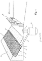
- Figures 1-3 show a leaching protector according to the state of the art showed in US5799948 (A ).
- the covering layer 1 rests upon the projectile-arresting material 3, and it is joined together with vulcanised overlapping joints.
- the terminating ends of the covering layer 1 are, in all directions, fastened to the backing layer 2 by means of said fastening devices 4. At the lowermost end, the covering layer 1 is fastened to a collection gutter formed by the backing layer 2, likewise by means of a fastening device 4.
- the backing layer 2 is shaped by forming side walls and upper and lower longitudinal walls into a box-shaped structure, adapted to the selected arresting material and the locational demands applied to the device.
- Glued-on supports of fibreglass-reinforced polyester may be necessary as a support for the backing layer 2 at the upper and lower walls in case the arresting material layer is thick.
- Fastening devices made of corrosion resistant flat steel support elements, pulled together by screw connections, with layers 1 and 2 between them, into a watertight attachment.
- a drain pipe 5 of perforated resin placed at the bottom of the collection gutter formed by the fibreglass reinforced polyester at the lowermost end of the backing layer 2, and connected to a wall outlet 7.
- An outlet connector 6 having a suitable dimension for connection to a discharge pipe 9, fitting in a watertight connection to said wall outlet 7.
- An anti-slide protector 8 may be necessary, depending on the inclination angle and the selected arresting material, in which case such devices are placed at a suitable angle on the backing layer 2 in the form of glued-in wooden ribs 8, appropriately spaced so as to prevent the selected arresting material 3 from sliding downwards.
- a collection reservoir 10 for the drainage water is provided.
- the device is drained from leach water via the sealed resin pipe 9, to be collected in the closed plastic resin reservoir 10 with its lid 11 for emptying and inspection.
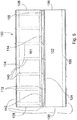
- FIG 4 shows a side view of a covering layer arrangement 100 for a leaching protector according to one embodiment of the present invention.
- the leaching protector may be constructed in the same way as described in US5799948 .
- the leaching protector of the present invention may be constructed in the same way as described in US5799948 , except for the above described outlet connector 6, the plastic resin wall outlet 7, the anti-slide protector 8, the discharge pipe 9, the collection reservoir 10 and the lid 11, described with reference to figures 1-3 .
- the drain pipe 5 can be sealed with a lid in each end and a drainage outlet connector can be arranged to the drain pipe 5.
- the outer free end of the drainage outlet connector can also be sealed with a lid.
- the drainage water collected in the drain pipe 5 can be discharged via the drainage outlet connector occasionally by removing the lid from the drainage outlet connector and connecting a discharging conduit to the end of the drainage outlet connector for emptying the water.
- the length of the drainage outlet connector approximately correspond the depth of the projectile-arresting material 3 such that the lid of the drainage outlet connector can be arranged just below the covering layer 1. Consequently, the upper free end of the drainage outlet connector and the lid can be hidden and the covering layer 1 is only opened occasionally for emptying the drainage water.
- the covering layer arrangement 100 is preferably inclined with approximately 30° with respect to the ground level.
- the covering layer arrangement 100 comprises a security layer 101 covering a security area 110 and a firing layer 102 covering a firing area 120.
- the probability of projectiles penetrating the security area 110 is low and the probability of projectiles penetrating the firing area 120 is high.
- the firing area 120 may be the area receiving more than 90-95% of all fired projectiles and the security area 110 may be the area which receives the rest of the fired projectiles.
- the security area 110 and the firing area 120 are best seen in figure 7.
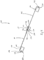
- Figure 7 shows the covering layer arrangement 100 seen obliquely from above. The figure is intended to show the principles of how the covering layer arrangement can be constructed.
- the measures and the relative sizes of the different parts of the invention are not to scale. For sake of clarity some details are not illustrated in figure 7 .
- the security area 110 is shown with dots and the firing area 120 is shown with stripes.
- the security area 110 and the firing area 120 are overlapping each other in a joint area 114.
- the security layer 101 is preferably positioned in the upper half of the covering layer arrangement 100 and the firing layer 102 is preferably positioned in the lower half of the covering layer arrangement 100.
- the security layer 101 can e.g. have a height of 4-6 meters and a width of about 30-80 meters.
- the firing layer 102 can e.g. have a height of 7 meters and a width of about 30-80 meters. Both the security layer 101 and the firing layer 102 are supported by the projectile arresting material positioned under the layers (not illustrated).
- the security layer 101 will not be frequently penetrated and it is optimised to have a high tensile strength and a high durability. It can e.g. be made of reinforced rubber fabric of synthetic rubber or of other elastomers with reinforcing material adapted to resist tensile forces and tearing.
- the material of the security layer 101 can be made thinner than the material of the firing layer 102 since the number of penetrations is negligible in comparison with the firing layer 102 and the penetrations are more spread which minimises the risk of large holes.
- the security layer 101 can be made of several smaller pieces of fabrics which are bonded together to form one large fabric.
- the security layer 101 has an upper edge 122, a lower edge 124 and two side edges 126 and 128 (see figure 5 ).
- the upper edge 122 of the security layer 101 is attached to a first support element 104 which extends along the upper edge of the security layer 101.
- the security layer 101 can e.g. be attached to the first support element 104 by means of a clamping strip 142 and fastening devices 112 like e.g. screw joints.
- the firing layer 102 will be frequently penetrated and is optimised to exhibit a very small entry hole after penetration.
- the size of a penetration hole after penetration by a projectile may be between 0.0 - 0.5 mm depending on the size of the projectile. It is undesired to have large penetration holes, since this will permit rain water to enter into the leaching protector.
- the firing layer 102 can be a fabric made of crude rubber or other elastomers like e.g. polyurethane.
- the firing layer 102 can be made of several smaller pieces of fabrics which are bonded together to form one large fabric.
- the firing layer 102 has an upper edge 132, a lower edge 134 and two side edges 136 and 138 (see figure 5 ).
- the lower edge 134 of the firing layer 102 is attached to a second support element 106 which extends along the lower edge 134 of the firing layer 101.
- the firing layer 102 can e.g. be attached to the second support element 106 by means of a clamping strip 142 and fastening devices 112 like e.g. screw joints.
- the lower edge 124 of the security layer 101 and upper edge 132 of the firing layer 102 are overlapping each other in the joint area 114 and both layers are connected to a third support element 108 which extends along the lower edge of the security layer 101 and the upper edge of the firing layer 102.
- the third support element can e.g. be a solid high density polyethylene support element. It can also be a tubular support element or a support element made of a penetrable material which does not cause any ricochets.
- the security layer 101 and the firing layer 102 are connected to the third support element 108 by means of clamping strips 142 and fastening devices 112 like e.g. screw joints.
- the side edges 126 and 128 of the security layer and the side edges 136, 138 of the firing layer can e.g. be attached with clamping devices to the sides of the leaching protector.
- the security layer 101 has a relatively high tensile strength, it must withstand the forces from wind, snow and from the weight of the third support element 108 and the firing layer 102 as well as the tensile forces from the stretching of the layer and from the weight of entering wild animals or humans. Since it is difficult to combine the high tensile strength and elastic properties of the security layer 101 in order to minimise the penetration holes, support straps 140 are provided as illustrated in figure 5 .
- the support straps are arranged under the security layer 101, so that the support straps 140 are covered by the security layer 101.
- the upper end of the support straps are connected to the first support element 104 by means of fastening devices 112.
- the lower end of the support straps 140 may be winded round the third support element 108 and are attached to the third support element 108 by means of fastening means 112.
- the support straps 140 can have a width of e.g. 50 mm and they can be arranged with an interval of e.g. 1 meter. They can e.g. be woven and/or be made of polypropylene. They are preferably arranged to handle penetrations without breaking.
- the support straps 140 are adapted to carry the load of the third support element 108 and of the firing layer 102 alone during the mounting procedure. When the security layer 101 is mounted, the security layer 101 helps carrying the permanent load from e.g. snow and wind and also the stress from the firing layer.
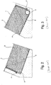
- Figure 5 shows schematically the covering layer arrangement 100 seen obliquely from above.
- the parts of the covering layer arrangement 100 which are hidden by the security layer 101 or by the firing layer 102, are shown with dashed lines.
- the figure is intended to show the principles of how the covering layer arrangement can be constructed. The measures and the relative sizes of the different parts of the invention are not to scale.
- Figure 6 shows the covering layer arrangement 100, depicted in the same view as in figure 5 , but without the hidden parts.
- Figure 7 shows the covering layer arrangement 100, depicted in the same view as in figure 5 or 6 , but aims at illustrating the support area 110 and the firing area 120.
Landscapes
- Engineering & Computer Science (AREA)
- General Engineering & Computer Science (AREA)
- Aiming, Guidance, Guns With A Light Source, Armor, Camouflage, And Targets (AREA)
- Emergency Lowering Means (AREA)
- Laminated Bodies (AREA)
Claims (10)
- Protecteur de lessivage pour champs de tir extérieurs, comprenant :- un agencement de couches de recouvrement élastiques (100),- un matériau anti-projectile, et- un dispositif de drainage,l'agencement de couches de recouvrement (100) comprenant une couche de sécurité (101) recouvrant une zone de sécurité (110) ayant une faible probabilité de recevoir des projectiles tirés, et une couche de tir (102) recouvrant une zone de tir (120) ayant une forte probabilité de recevoir des projectiles tirés, la couche de sécurité (101) et la couche de tir (102) étant pénétrables par des projectiles, la couche de sécurité (101) et la couche de tir (102) étant des couches séparées, la couche de sécurité (101) est faite d'un premier matériau et la couche de tir (102) est faite d'un deuxième matériau, caractérisé en ce que la couche de sécurité (101) est positionnée dans la moitié supérieure de la couche de recouvrement, et la couche de tir (102) est positionnée dans la moitié inférieure de la couche de recouvrement, un bord supérieur (132) de la couche de tir (102) et un bord inférieur (124) de la couche de sécurité (101) étant reliés à un élément de support (108), qui s'étend le long du bord inférieur de la couche de sécurité (101) et du bord supérieur de la couche de tir (102), au moyen de bandes de serrage (142) et de moyens de fixation (112).
- Protecteur de lessivage selon la revendication 1, dans lequel l'agencement (100) comprend un premier élément de support (104), un deuxième élément de support (106), dans lequel l'élément de support (108) auquel la partie supérieure (132) de la couche de tir (102) et un bord inférieur (124) de la couche de sécurité (101) sont reliés est un troisième élément de support (108), dans lequel un bord supérieur (122) de la couche de sécurité (101) est relié au premier élément de support (104), et un bord inférieur (134) de la couche de tir (101) est relié au deuxième élément de support (106).
- Protecteur de lessivage selon la revendication 2, dans lequel le bord supérieur de la couche de sécurité (101) et le bord inférieur de la couche de tir (101) sont reliés aux premier (104) et deuxième (106) éléments de support au moyen de bandes de serrage (142) et de moyens de fixation (112).
- Protecteur de lessivage selon l'une quelconque des revendications 2 à 3, dans lequel l'agencement (100) comprend au moins une sangle de support (140), ladite sangle de support (140) étant reliée par une première extrémité au premier élément de support (104) et par une deuxième extrémité au troisième élément de support (108).
- Protecteur de lessivage selon la revendication 4, dans lequel la sangle de support (140) est reliée au premier élément de support (104) au moyen de bandes de serrage (142) et de moyens de fixation (112) et la sangle de support (140) est reliée au troisième élément de support (108) au moyen de moyens de fixation (112).
- Protecteur de lessivage selon l'une quelconque des revendications 1 à 5, dans lequel la couche de tir (102) est faite d'un matériau élastique si bien que la couche de tir (102) présente un très petit trou d'entrée après la pénétration d'un projectile.
- Protecteur de lessivage selon la revendication 6, dans lequel la couche de tir (102) est faite de caoutchouc ou d'autres élastomères tels que par ex. polyuréthane.
- Protecteur de lessivage selon l'une quelconque des revendications 1 à 7, dans lequel la couche de sécurité (101) est faite d'un matériau élastique ayant une résistance élevée à la traction et une durabilité élevée, tel que tissu de caoutchouc renforcé de caoutchouc synthétique ou d'autres élastomères avec un matériau de renforcement adapté pour résister à des forces de traction et à des déchirures.
- Protecteur de lessivage selon l'une quelconque des revendications 4 à 5, dans lequel la bande de support (140) est tissée et / ou est faite en polypropylène.
- Protecteur de lessivage selon l'une quelconque des revendications 1 à 8, dans lequel la couche de tir (102) et la couche de sécurité (101) se chevauchent dans une zone de joint (114).
Priority Applications (1)
| Application Number | Priority Date | Filing Date | Title |
|---|---|---|---|
| PL13800626T PL2856071T3 (pl) | 2012-06-04 | 2013-05-31 | Ochraniacz ługujący do strzelnic plenerowych |
Applications Claiming Priority (2)
| Application Number | Priority Date | Filing Date | Title |
|---|---|---|---|
| SE1250579A SE536516C2 (sv) | 2012-06-04 | 2012-06-04 | Urlakningsskydd för skjutbanor utomhus |
| PCT/SE2013/050638 WO2013184062A1 (fr) | 2012-06-04 | 2013-05-31 | Protecteur de lessivage pour champs de tir extérieurs |
Publications (3)
| Publication Number | Publication Date |
|---|---|
| EP2856071A1 EP2856071A1 (fr) | 2015-04-08 |
| EP2856071A4 EP2856071A4 (fr) | 2015-11-18 |
| EP2856071B1 true EP2856071B1 (fr) | 2018-05-23 |
Family
ID=49712338
Family Applications (1)
| Application Number | Title | Priority Date | Filing Date |
|---|---|---|---|
| EP13800626.7A Active EP2856071B1 (fr) | 2012-06-04 | 2013-05-31 | Protecteur de lessivage pour champs de tir extérieurs |
Country Status (11)
| Country | Link |
|---|---|
| US (1) | US10066909B2 (fr) |
| EP (1) | EP2856071B1 (fr) |
| JP (1) | JP2015522787A (fr) |
| CN (1) | CN104335004B (fr) |
| CA (1) | CA2870135C (fr) |
| DK (1) | DK2856071T3 (fr) |
| ES (1) | ES2680219T3 (fr) |
| PL (1) | PL2856071T3 (fr) |
| SE (1) | SE536516C2 (fr) |
| WO (1) | WO2013184062A1 (fr) |
| ZA (1) | ZA201408134B (fr) |
Families Citing this family (1)
| Publication number | Priority date | Publication date | Assignee | Title |
|---|---|---|---|---|
| SE1950454A1 (en) | 2019-04-11 | 2020-10-12 | Bap Pats S R O | A projectile arresting device and a method for preparing a projectile arresting device |
Family Cites Families (28)
| Publication number | Priority date | Publication date | Assignee | Title |
|---|---|---|---|---|
| US579948A (en) * | 1897-04-06 | Automatic feeding-machine for sawing materials | ||
| JPS576577Y2 (fr) * | 1978-06-19 | 1982-02-08 | ||
| US4741132A (en) * | 1981-06-17 | 1988-05-03 | Emblin Robert T | Multiple panel metal roofing system with overlapping panel edges |
| JPS5845748U (ja) * | 1981-09-19 | 1983-03-28 | 大日通商有限会社 | 連結シ−ト |
| EG16973A (en) | 1984-06-01 | 1993-12-30 | Impressa Construzioni Soc Fra | Ballistic projectile arrester, having a generation and or recovery system for the impact material swited to fires with small arms or others, in particular in indoors firing grounds |
| JPS60135326U (ja) * | 1984-12-24 | 1985-09-09 | 押川 真人 | 河川,貯水池等の法面における防護装置 |
| JPS6229610A (ja) * | 1985-07-31 | 1987-02-07 | Ohbayashigumi Ltd | 土壌地盤面の防水工法 |
| US4786059A (en) * | 1985-12-20 | 1988-11-22 | A B C Appalti Bonifiche E Costruzioni Di Elio Floria & C.S.A.S. | Equipment with energy knocking-down septum for bullets, to be installed in shooting ranges |
| JPS6312228A (ja) * | 1986-07-02 | 1988-01-19 | 徳増 陽司 | 地表シ−ト張方法 |
| US4773653A (en) * | 1987-01-20 | 1988-09-27 | Linatex Corporation Of America | Cover for ballistic target assembly |
| GB2242730A (en) | 1990-04-07 | 1991-10-09 | John Alan Vertanness | Bullet trap |
| US5848794A (en) * | 1991-01-18 | 1998-12-15 | Caswell International Corporation | Granulate backstop assembly |
| JPH0730538B2 (ja) * | 1992-09-18 | 1995-04-05 | 山水産業株式会社 | 遮水シート固定用接手シート |
| DE4317742A1 (de) * | 1993-05-27 | 1994-12-01 | Spieth Ernst K Gmbh | Geschoßfang und Geschoßfangkasten für einen solchen Geschoßfang |
| JP3007541B2 (ja) * | 1994-11-04 | 2000-02-07 | バブコック日立株式会社 | 停弾装置 |
| DE4441559A1 (de) * | 1994-11-22 | 1996-05-23 | Philipps Claus Hermann Dipl In | Geschoßfangsystem für Raumschießanlagen |
| DE29521148U1 (de) * | 1995-03-08 | 1996-09-19 | Ernst K. Spieth Gmbh, 73730 Esslingen | Geschoßfang für Streubeschuß |
| SE505107C2 (sv) * | 1995-10-17 | 1997-06-23 | Gerth Moberg | Urlakningsskydd |
| JP2003287399A (ja) * | 2002-03-28 | 2003-10-10 | Sumitomo Electric Ind Ltd | 銃弾回収装置及びその方法 |
| RU2213320C1 (ru) | 2002-06-24 | 2003-09-27 | Институт прикладной механики УрО РАН | Световая мишень |
| US7134664B2 (en) * | 2002-12-02 | 2006-11-14 | The United States Of America As Represented By The Secretary Of The Army | Modular bullet trap cover |
| EP1588117B1 (fr) * | 2003-01-20 | 2009-03-18 | Gerth Moberg | Dispositif pour champs de tir |
| WO2004068060A1 (fr) * | 2003-01-31 | 2004-08-12 | Svenska Pistolskytteförbundet | Procede permettant d'empecher la dispersion non controlee de produits metalliques degrades a partir d'une butte de tir sur un champ de tir et butte de tir permettant la mise en oeuvre dudit procede |
| US6715761B1 (en) * | 2003-03-14 | 2004-04-06 | Gerth Moberg | Apparatus for shooting ranges |
| JP2005188894A (ja) * | 2003-12-26 | 2005-07-14 | Babcock Hitachi Kk | 停弾装置 |
| DE202005002672U1 (de) * | 2005-02-19 | 2005-05-19 | Gerd Bücheler Schießanlagen und Schießstandbau | Abbremsvorrichtung |
| KR101087283B1 (ko) * | 2008-12-24 | 2011-11-29 | 오인규 | 탄두 회수 장치 |
| US20110233869A1 (en) * | 2010-03-25 | 2011-09-29 | John Ernest M | Ballistic paneling for bullet traps |
-
2012
- 2012-06-04 SE SE1250579A patent/SE536516C2/sv unknown
-
2013
- 2013-05-31 EP EP13800626.7A patent/EP2856071B1/fr active Active
- 2013-05-31 JP JP2015515982A patent/JP2015522787A/ja active Pending
- 2013-05-31 CN CN201380025148.4A patent/CN104335004B/zh active Active
- 2013-05-31 PL PL13800626T patent/PL2856071T3/pl unknown
- 2013-05-31 CA CA2870135A patent/CA2870135C/fr active Active
- 2013-05-31 US US14/404,921 patent/US10066909B2/en active Active
- 2013-05-31 WO PCT/SE2013/050638 patent/WO2013184062A1/fr active Application Filing
- 2013-05-31 DK DK13800626.7T patent/DK2856071T3/en active
- 2013-05-31 ES ES13800626.7T patent/ES2680219T3/es active Active
-
2014
- 2014-11-06 ZA ZA2014/08134A patent/ZA201408134B/en unknown
Non-Patent Citations (1)
| Title |
|---|
| None * |
Also Published As
| Publication number | Publication date |
|---|---|
| CN104335004A (zh) | 2015-02-04 |
| PL2856071T3 (pl) | 2018-10-31 |
| SE1250579A1 (sv) | 2013-12-05 |
| ES2680219T3 (es) | 2018-09-05 |
| US10066909B2 (en) | 2018-09-04 |
| SE536516C2 (sv) | 2014-01-21 |
| CA2870135A1 (fr) | 2013-12-12 |
| DK2856071T3 (en) | 2018-08-06 |
| CA2870135C (fr) | 2020-12-15 |
| ZA201408134B (en) | 2015-12-23 |
| EP2856071A4 (fr) | 2015-11-18 |
| US20150123347A1 (en) | 2015-05-07 |
| JP2015522787A (ja) | 2015-08-06 |
| EP2856071A1 (fr) | 2015-04-08 |
| WO2013184062A1 (fr) | 2013-12-12 |
| CN104335004B (zh) | 2016-09-28 |
Similar Documents
| Publication | Publication Date | Title |
|---|---|---|
| US10053867B2 (en) | Apparatus for diverting water | |
| US20160040820A1 (en) | Downspout end cap | |
| RU2525771C2 (ru) | Устройство защиты, по меньшей мере, одного трубопровода, проложенного на дне водного бассейна, и соответствующая система транспортировки текучей среды | |
| EP2856071B1 (fr) | Protecteur de lessivage pour champs de tir extérieurs | |
| US9726464B2 (en) | Projectile arresting module and projectile arresting arrangement | |
| US5799948A (en) | Leaching protector | |
| EP3134701B1 (fr) | Dispositif d'arrêt de projectile et agencement d'arrêt de projectile | |
| CA2847436A1 (fr) | Remplacement d'agregat | |
| ES2268249T3 (es) | Disposicion de recogida de perdigones. | |
| US20200326164A1 (en) | Projectile arresting device and a method for preparing a projectile arresting device | |
| US7185892B2 (en) | Apparatus for shooting ranges | |
| CZ20536U1 (cs) | Lyzimetrická sonda | |
| DE19613723C1 (de) | Umhauste Anlage für das sportliche und/oder jagdliche und/oder behördliche Schießen mit Schußwaffen | |
| US20160067530A1 (en) | Air gully manifold | |
| JP2011026845A (ja) | 軒先用雪止め装置 | |
| JP2007010302A (ja) | 射撃場鉛弾環境汚染防止装置 | |
| DE29913841U1 (de) | Schießsportanlage |
Legal Events
| Date | Code | Title | Description |
|---|---|---|---|
| PUAI | Public reference made under article 153(3) epc to a published international application that has entered the european phase |
Free format text: ORIGINAL CODE: 0009012 |
|
| 17P | Request for examination filed |
Effective date: 20141017 |
|
| AK | Designated contracting states |
Kind code of ref document: A1 Designated state(s): AL AT BE BG CH CY CZ DE DK EE ES FI FR GB GR HR HU IE IS IT LI LT LU LV MC MK MT NL NO PL PT RO RS SE SI SK SM TR |
|
| AX | Request for extension of the european patent |
Extension state: BA ME |
|
| DAX | Request for extension of the european patent (deleted) | ||
| RA4 | Supplementary search report drawn up and despatched (corrected) |
Effective date: 20151015 |
|
| RIC1 | Information provided on ipc code assigned before grant |
Ipc: F41J 13/00 20090101AFI20151009BHEP |
|
| STAA | Information on the status of an ep patent application or granted ep patent |
Free format text: STATUS: EXAMINATION IS IN PROGRESS |
|
| 17Q | First examination report despatched |
Effective date: 20170412 |
|
| GRAP | Despatch of communication of intention to grant a patent |
Free format text: ORIGINAL CODE: EPIDOSNIGR1 |
|
| STAA | Information on the status of an ep patent application or granted ep patent |
Free format text: STATUS: GRANT OF PATENT IS INTENDED |
|
| INTG | Intention to grant announced |
Effective date: 20171212 |
|
| RIN1 | Information on inventor provided before grant (corrected) |
Inventor name: MOBERG, GERTH |
|
| GRAS | Grant fee paid |
Free format text: ORIGINAL CODE: EPIDOSNIGR3 |
|
| GRAA | (expected) grant |
Free format text: ORIGINAL CODE: 0009210 |
|
| STAA | Information on the status of an ep patent application or granted ep patent |
Free format text: STATUS: THE PATENT HAS BEEN GRANTED |
|
| AK | Designated contracting states |
Kind code of ref document: B1 Designated state(s): AL AT BE BG CH CY CZ DE DK EE ES FI FR GB GR HR HU IE IS IT LI LT LU LV MC MK MT NL NO PL PT RO RS SE SI SK SM TR |
|
| REG | Reference to a national code |
Ref country code: GB Ref legal event code: FG4D |
|
| REG | Reference to a national code |
Ref country code: CH Ref legal event code: EP |
|
| REG | Reference to a national code |
Ref country code: IE Ref legal event code: FG4D |
|
| REG | Reference to a national code |
Ref country code: AT Ref legal event code: REF Ref document number: 1001857 Country of ref document: AT Kind code of ref document: T Effective date: 20180615 |
|
| REG | Reference to a national code |
Ref country code: DE Ref legal event code: R096 Ref document number: 602013037876 Country of ref document: DE |
|
| REG | Reference to a national code |
Ref country code: FR Ref legal event code: PLFP Year of fee payment: 6 |
|
| REG | Reference to a national code |
Ref country code: DK Ref legal event code: T3 Effective date: 20180730 |
|
| REG | Reference to a national code |
Ref country code: SE Ref legal event code: TRGR |
|
| REG | Reference to a national code |
Ref country code: ES Ref legal event code: FG2A Ref document number: 2680219 Country of ref document: ES Kind code of ref document: T3 Effective date: 20180905 |
|
| REG | Reference to a national code |
Ref country code: NL Ref legal event code: MP Effective date: 20180523 |
|
| REG | Reference to a national code |
Ref country code: LT Ref legal event code: MG4D |
|
| REG | Reference to a national code |
Ref country code: NO Ref legal event code: T2 Effective date: 20180523 |
|
| PG25 | Lapsed in a contracting state [announced via postgrant information from national office to epo] |
Ref country code: LT Free format text: LAPSE BECAUSE OF FAILURE TO SUBMIT A TRANSLATION OF THE DESCRIPTION OR TO PAY THE FEE WITHIN THE PRESCRIBED TIME-LIMIT Effective date: 20180523 Ref country code: BG Free format text: LAPSE BECAUSE OF FAILURE TO SUBMIT A TRANSLATION OF THE DESCRIPTION OR TO PAY THE FEE WITHIN THE PRESCRIBED TIME-LIMIT Effective date: 20180823 |
|
| PG25 | Lapsed in a contracting state [announced via postgrant information from national office to epo] |
Ref country code: GR Free format text: LAPSE BECAUSE OF FAILURE TO SUBMIT A TRANSLATION OF THE DESCRIPTION OR TO PAY THE FEE WITHIN THE PRESCRIBED TIME-LIMIT Effective date: 20180824 Ref country code: RS Free format text: LAPSE BECAUSE OF FAILURE TO SUBMIT A TRANSLATION OF THE DESCRIPTION OR TO PAY THE FEE WITHIN THE PRESCRIBED TIME-LIMIT Effective date: 20180523 Ref country code: LV Free format text: LAPSE BECAUSE OF FAILURE TO SUBMIT A TRANSLATION OF THE DESCRIPTION OR TO PAY THE FEE WITHIN THE PRESCRIBED TIME-LIMIT Effective date: 20180523 Ref country code: HR Free format text: LAPSE BECAUSE OF FAILURE TO SUBMIT A TRANSLATION OF THE DESCRIPTION OR TO PAY THE FEE WITHIN THE PRESCRIBED TIME-LIMIT Effective date: 20180523 Ref country code: NL Free format text: LAPSE BECAUSE OF FAILURE TO SUBMIT A TRANSLATION OF THE DESCRIPTION OR TO PAY THE FEE WITHIN THE PRESCRIBED TIME-LIMIT Effective date: 20180523 |
|
| REG | Reference to a national code |
Ref country code: CH Ref legal event code: PL |
|
| REG | Reference to a national code |
Ref country code: BE Ref legal event code: MM Effective date: 20180531 |
|
| PG25 | Lapsed in a contracting state [announced via postgrant information from national office to epo] |
Ref country code: SK Free format text: LAPSE BECAUSE OF FAILURE TO SUBMIT A TRANSLATION OF THE DESCRIPTION OR TO PAY THE FEE WITHIN THE PRESCRIBED TIME-LIMIT Effective date: 20180523 Ref country code: EE Free format text: LAPSE BECAUSE OF FAILURE TO SUBMIT A TRANSLATION OF THE DESCRIPTION OR TO PAY THE FEE WITHIN THE PRESCRIBED TIME-LIMIT Effective date: 20180523 Ref country code: RO Free format text: LAPSE BECAUSE OF FAILURE TO SUBMIT A TRANSLATION OF THE DESCRIPTION OR TO PAY THE FEE WITHIN THE PRESCRIBED TIME-LIMIT Effective date: 20180523 |
|
| REG | Reference to a national code |
Ref country code: DE Ref legal event code: R097 Ref document number: 602013037876 Country of ref document: DE |
|
| PG25 | Lapsed in a contracting state [announced via postgrant information from national office to epo] |
Ref country code: LI Free format text: LAPSE BECAUSE OF NON-PAYMENT OF DUE FEES Effective date: 20180531 Ref country code: SM Free format text: LAPSE BECAUSE OF FAILURE TO SUBMIT A TRANSLATION OF THE DESCRIPTION OR TO PAY THE FEE WITHIN THE PRESCRIBED TIME-LIMIT Effective date: 20180523 Ref country code: CH Free format text: LAPSE BECAUSE OF NON-PAYMENT OF DUE FEES Effective date: 20180531 |
|
| REG | Reference to a national code |
Ref country code: IE Ref legal event code: MM4A |
|
| PG25 | Lapsed in a contracting state [announced via postgrant information from national office to epo] |
Ref country code: MC Free format text: LAPSE BECAUSE OF FAILURE TO SUBMIT A TRANSLATION OF THE DESCRIPTION OR TO PAY THE FEE WITHIN THE PRESCRIBED TIME-LIMIT Effective date: 20180523 Ref country code: LU Free format text: LAPSE BECAUSE OF NON-PAYMENT OF DUE FEES Effective date: 20180531 |
|
| PLBE | No opposition filed within time limit |
Free format text: ORIGINAL CODE: 0009261 |
|
| STAA | Information on the status of an ep patent application or granted ep patent |
Free format text: STATUS: NO OPPOSITION FILED WITHIN TIME LIMIT |
|
| PG25 | Lapsed in a contracting state [announced via postgrant information from national office to epo] |
Ref country code: IE Free format text: LAPSE BECAUSE OF NON-PAYMENT OF DUE FEES Effective date: 20180531 |
|
| 26N | No opposition filed |
Effective date: 20190226 |
|
| PG25 | Lapsed in a contracting state [announced via postgrant information from national office to epo] |
Ref country code: SI Free format text: LAPSE BECAUSE OF FAILURE TO SUBMIT A TRANSLATION OF THE DESCRIPTION OR TO PAY THE FEE WITHIN THE PRESCRIBED TIME-LIMIT Effective date: 20180523 Ref country code: BE Free format text: LAPSE BECAUSE OF NON-PAYMENT OF DUE FEES Effective date: 20180531 |
|
| PG25 | Lapsed in a contracting state [announced via postgrant information from national office to epo] |
Ref country code: AL Free format text: LAPSE BECAUSE OF FAILURE TO SUBMIT A TRANSLATION OF THE DESCRIPTION OR TO PAY THE FEE WITHIN THE PRESCRIBED TIME-LIMIT Effective date: 20180523 |
|
| PG25 | Lapsed in a contracting state [announced via postgrant information from national office to epo] |
Ref country code: MT Free format text: LAPSE BECAUSE OF NON-PAYMENT OF DUE FEES Effective date: 20180531 |
|
| PG25 | Lapsed in a contracting state [announced via postgrant information from national office to epo] |
Ref country code: TR Free format text: LAPSE BECAUSE OF FAILURE TO SUBMIT A TRANSLATION OF THE DESCRIPTION OR TO PAY THE FEE WITHIN THE PRESCRIBED TIME-LIMIT Effective date: 20180523 |
|
| PG25 | Lapsed in a contracting state [announced via postgrant information from national office to epo] |
Ref country code: PT Free format text: LAPSE BECAUSE OF FAILURE TO SUBMIT A TRANSLATION OF THE DESCRIPTION OR TO PAY THE FEE WITHIN THE PRESCRIBED TIME-LIMIT Effective date: 20180523 |
|
| PG25 | Lapsed in a contracting state [announced via postgrant information from national office to epo] |
Ref country code: MK Free format text: LAPSE BECAUSE OF NON-PAYMENT OF DUE FEES Effective date: 20180523 Ref country code: CY Free format text: LAPSE BECAUSE OF FAILURE TO SUBMIT A TRANSLATION OF THE DESCRIPTION OR TO PAY THE FEE WITHIN THE PRESCRIBED TIME-LIMIT Effective date: 20180523 Ref country code: HU Free format text: LAPSE BECAUSE OF FAILURE TO SUBMIT A TRANSLATION OF THE DESCRIPTION OR TO PAY THE FEE WITHIN THE PRESCRIBED TIME-LIMIT; INVALID AB INITIO Effective date: 20130531 |
|
| PG25 | Lapsed in a contracting state [announced via postgrant information from national office to epo] |
Ref country code: IS Free format text: LAPSE BECAUSE OF FAILURE TO SUBMIT A TRANSLATION OF THE DESCRIPTION OR TO PAY THE FEE WITHIN THE PRESCRIBED TIME-LIMIT Effective date: 20180923 |
|
| REG | Reference to a national code |
Ref country code: AT Ref legal event code: UEP Ref document number: 1001857 Country of ref document: AT Kind code of ref document: T Effective date: 20180523 |
|
| PGFP | Annual fee paid to national office [announced via postgrant information from national office to epo] |
Ref country code: ES Payment date: 20230609 Year of fee payment: 11 |
|
| PGFP | Annual fee paid to national office [announced via postgrant information from national office to epo] |
Ref country code: SE Payment date: 20240326 Year of fee payment: 12 Ref country code: FR Payment date: 20240326 Year of fee payment: 12 |
|
| PGFP | Annual fee paid to national office [announced via postgrant information from national office to epo] |
Ref country code: GB Payment date: 20240403 Year of fee payment: 12 |
|
| PGFP | Annual fee paid to national office [announced via postgrant information from national office to epo] |
Ref country code: DE Payment date: 20240417 Year of fee payment: 12 |
|
| PGFP | Annual fee paid to national office [announced via postgrant information from national office to epo] |
Ref country code: DK Payment date: 20240408 Year of fee payment: 12 |
|
| PGFP | Annual fee paid to national office [announced via postgrant information from national office to epo] |
Ref country code: AT Payment date: 20240415 Year of fee payment: 12 Ref country code: CZ Payment date: 20240328 Year of fee payment: 12 |
|
| PGFP | Annual fee paid to national office [announced via postgrant information from national office to epo] |
Ref country code: NO Payment date: 20240424 Year of fee payment: 12 Ref country code: IT Payment date: 20240417 Year of fee payment: 12 Ref country code: FI Payment date: 20240419 Year of fee payment: 12 |
|
| PGFP | Annual fee paid to national office [announced via postgrant information from national office to epo] |
Ref country code: PL Payment date: 20240426 Year of fee payment: 12 |