EP2855152B1 - A lithographic printing plate precursor - Google Patents
A lithographic printing plate precursor Download PDFInfo
- Publication number
- EP2855152B1 EP2855152B1 EP13710855.1A EP13710855A EP2855152B1 EP 2855152 B1 EP2855152 B1 EP 2855152B1 EP 13710855 A EP13710855 A EP 13710855A EP 2855152 B1 EP2855152 B1 EP 2855152B1
- Authority
- EP
- European Patent Office
- Prior art keywords
- group
- silox
- precursor
- coating
- polysiloxane
- Prior art date
- Legal status (The legal status is an assumption and is not a legal conclusion. Google has not performed a legal analysis and makes no representation as to the accuracy of the status listed.)
- Not-in-force
Links
- 238000007639 printing Methods 0.000 title claims description 139
- 239000002243 precursor Substances 0.000 title claims description 86
- -1 polysiloxane Polymers 0.000 claims description 106
- 238000000576 coating method Methods 0.000 claims description 82
- 239000011248 coating agent Substances 0.000 claims description 80
- 150000001875 compounds Chemical class 0.000 claims description 66
- 229920001296 polysiloxane Polymers 0.000 claims description 55
- 150000003961 organosilicon compounds Chemical class 0.000 claims description 53
- 239000011230 binding agent Substances 0.000 claims description 27
- 150000003254 radicals Chemical class 0.000 claims description 24
- 238000000034 method Methods 0.000 claims description 21
- 125000003118 aryl group Chemical group 0.000 claims description 20
- 125000002496 methyl group Chemical group [H]C([H])([H])* 0.000 claims description 19
- 125000001072 heteroaryl group Chemical group 0.000 claims description 17
- 125000005647 linker group Chemical group 0.000 claims description 17
- 125000002887 hydroxy group Chemical group [H]O* 0.000 claims description 16
- 125000003342 alkenyl group Chemical group 0.000 claims description 15
- 125000000547 substituted alkyl group Chemical group 0.000 claims description 15
- 125000000304 alkynyl group Chemical group 0.000 claims description 14
- 125000004432 carbon atom Chemical group C* 0.000 claims description 14
- 125000000753 cycloalkyl group Chemical group 0.000 claims description 14
- 125000002947 alkylene group Chemical group 0.000 claims description 13
- 239000001257 hydrogen Substances 0.000 claims description 12
- 229910052739 hydrogen Inorganic materials 0.000 claims description 12
- 150000003839 salts Chemical class 0.000 claims description 12
- 239000003505 polymerization initiator Substances 0.000 claims description 11
- 125000002252 acyl group Chemical group 0.000 claims description 10
- 125000003545 alkoxy group Chemical group 0.000 claims description 9
- 229910052799 carbon Inorganic materials 0.000 claims description 8
- 125000004104 aryloxy group Chemical group 0.000 claims description 7
- 125000002993 cycloalkylene group Chemical group 0.000 claims description 7
- UFHFLCQGNIYNRP-UHFFFAOYSA-N Hydrogen Chemical compound [H][H] UFHFLCQGNIYNRP-UHFFFAOYSA-N 0.000 claims description 6
- 125000004423 acyloxy group Chemical group 0.000 claims description 6
- 125000000732 arylene group Chemical group 0.000 claims description 6
- 125000005549 heteroarylene group Chemical group 0.000 claims description 6
- 230000005660 hydrophilic surface Effects 0.000 claims description 6
- XUIMIQQOPSSXEZ-UHFFFAOYSA-N Silicon Chemical group [Si] XUIMIQQOPSSXEZ-UHFFFAOYSA-N 0.000 claims description 5
- QAOWNCQODCNURD-UHFFFAOYSA-N Sulfuric acid Chemical compound OS(O)(=O)=O QAOWNCQODCNURD-UHFFFAOYSA-N 0.000 claims description 5
- 150000001732 carboxylic acid derivatives Chemical class 0.000 claims description 5
- 125000001931 aliphatic group Chemical group 0.000 claims description 4
- 125000004435 hydrogen atom Chemical group [H]* 0.000 claims description 3
- 125000005496 phosphonium group Chemical group 0.000 claims description 3
- 125000001453 quaternary ammonium group Chemical group 0.000 claims description 3
- BDHFUVZGWQCTTF-UHFFFAOYSA-N sulfonic acid Chemical compound OS(=O)=O BDHFUVZGWQCTTF-UHFFFAOYSA-N 0.000 claims description 3
- 239000001117 sulphuric acid Substances 0.000 claims description 3
- 235000011149 sulphuric acid Nutrition 0.000 claims description 3
- 125000000383 tetramethylene group Chemical group [H]C([H])([*:1])C([H])([H])C([H])([H])C([H])([H])[*:2] 0.000 claims description 2
- 125000001183 hydrocarbyl group Chemical group 0.000 claims 2
- 239000010410 layer Substances 0.000 description 83
- 239000000243 solution Substances 0.000 description 49
- NIXOWILDQLNWCW-UHFFFAOYSA-M Acrylate Chemical compound [O-]C(=O)C=C NIXOWILDQLNWCW-UHFFFAOYSA-M 0.000 description 39
- LFQSCWFLJHTTHZ-UHFFFAOYSA-N Ethanol Chemical compound CCO LFQSCWFLJHTTHZ-UHFFFAOYSA-N 0.000 description 38
- 239000000203 mixture Substances 0.000 description 34
- HRPVXLWXLXDGHG-UHFFFAOYSA-N Acrylamide Chemical class NC(=O)C=C HRPVXLWXLXDGHG-UHFFFAOYSA-N 0.000 description 29
- 238000006243 chemical reaction Methods 0.000 description 26
- XLYOFNOQVPJJNP-UHFFFAOYSA-N water Substances O XLYOFNOQVPJJNP-UHFFFAOYSA-N 0.000 description 25
- 230000000052 comparative effect Effects 0.000 description 24
- 239000000049 pigment Substances 0.000 description 24
- 238000012545 processing Methods 0.000 description 24
- 239000000976 ink Substances 0.000 description 21
- 239000000178 monomer Substances 0.000 description 21
- 239000003999 initiator Substances 0.000 description 20
- 230000035945 sensitivity Effects 0.000 description 20
- 241001479434 Agfa Species 0.000 description 18
- 230000015572 biosynthetic process Effects 0.000 description 17
- 238000003384 imaging method Methods 0.000 description 17
- 125000000217 alkyl group Chemical group 0.000 description 16
- 239000000975 dye Substances 0.000 description 16
- 229920002451 polyvinyl alcohol Polymers 0.000 description 15
- SKKPKVRWHCKIAK-UHFFFAOYSA-N 2-triethoxysilylethylphosphonic acid Chemical compound CCO[Si](OCC)(OCC)CCP(O)(O)=O SKKPKVRWHCKIAK-UHFFFAOYSA-N 0.000 description 14
- XAGFODPZIPBFFR-UHFFFAOYSA-N aluminium Chemical compound [Al] XAGFODPZIPBFFR-UHFFFAOYSA-N 0.000 description 14
- 238000003786 synthesis reaction Methods 0.000 description 14
- 229910052782 aluminium Inorganic materials 0.000 description 13
- 239000003086 colorant Substances 0.000 description 13
- 238000011161 development Methods 0.000 description 13
- 230000018109 developmental process Effects 0.000 description 13
- 230000003287 optical effect Effects 0.000 description 12
- 235000019422 polyvinyl alcohol Nutrition 0.000 description 12
- 238000002360 preparation method Methods 0.000 description 12
- 239000004372 Polyvinyl alcohol Substances 0.000 description 11
- 125000001495 ethyl group Chemical group [H]C([H])([H])C([H])([H])* 0.000 description 11
- 238000010438 heat treatment Methods 0.000 description 11
- 229920000642 polymer Polymers 0.000 description 11
- LYCAIKOWRPUZTN-UHFFFAOYSA-N Ethylene glycol Chemical compound OCCO LYCAIKOWRPUZTN-UHFFFAOYSA-N 0.000 description 10
- 239000007864 aqueous solution Substances 0.000 description 10
- 239000003795 chemical substances by application Substances 0.000 description 10
- 239000007788 liquid Substances 0.000 description 10
- 230000001681 protective effect Effects 0.000 description 10
- 238000011282 treatment Methods 0.000 description 10
- YXIWHUQXZSMYRE-UHFFFAOYSA-N 1,3-benzothiazole-2-thiol Chemical compound C1=CC=C2SC(S)=NC2=C1 YXIWHUQXZSMYRE-UHFFFAOYSA-N 0.000 description 9
- IMROMDMJAWUWLK-UHFFFAOYSA-N Ethenol Chemical compound OC=C IMROMDMJAWUWLK-UHFFFAOYSA-N 0.000 description 9
- HEMHJVSKTPXQMS-UHFFFAOYSA-M Sodium hydroxide Chemical compound [OH-].[Na+] HEMHJVSKTPXQMS-UHFFFAOYSA-M 0.000 description 9
- ARXJGSRGQADJSQ-UHFFFAOYSA-N 1-methoxypropan-2-ol Chemical compound COCC(C)O ARXJGSRGQADJSQ-UHFFFAOYSA-N 0.000 description 8
- 239000004593 Epoxy Substances 0.000 description 8
- 239000002253 acid Substances 0.000 description 8
- 239000004411 aluminium Substances 0.000 description 8
- 125000001449 isopropyl group Chemical group [H]C([H])([H])C([H])(*)C([H])([H])[H] 0.000 description 8
- 238000012216 screening Methods 0.000 description 8
- 238000012360 testing method Methods 0.000 description 8
- GMIUUCWUOPOETN-UHFFFAOYSA-N 2,4,5-triphenyl-1-(2,4,5-triphenylimidazol-2-yl)imidazole Chemical compound C1=CC=CC=C1C1=NC(N2C(=C(N=C2C=2C=CC=CC=2)C=2C=CC=CC=2)C=2C=CC=CC=2)(C=2C=CC=CC=2)N=C1C1=CC=CC=C1 GMIUUCWUOPOETN-UHFFFAOYSA-N 0.000 description 7
- URDOJQUSEUXVRP-UHFFFAOYSA-N 3-triethoxysilylpropyl 2-methylprop-2-enoate Chemical compound CCO[Si](OCC)(OCC)CCCOC(=O)C(C)=C URDOJQUSEUXVRP-UHFFFAOYSA-N 0.000 description 7
- IAYPIBMASNFSPL-UHFFFAOYSA-N Ethylene oxide Chemical group C1CO1 IAYPIBMASNFSPL-UHFFFAOYSA-N 0.000 description 7
- 125000000484 butyl group Chemical group [H]C([*])([H])C([H])([H])C([H])([H])C([H])([H])[H] 0.000 description 7
- KPUWHANPEXNPJT-UHFFFAOYSA-N disiloxane Chemical class [SiH3]O[SiH3] KPUWHANPEXNPJT-UHFFFAOYSA-N 0.000 description 7
- 238000011156 evaluation Methods 0.000 description 7
- 239000004615 ingredient Substances 0.000 description 7
- 125000001436 propyl group Chemical group [H]C([*])([H])C([H])([H])C([H])([H])[H] 0.000 description 7
- 239000000758 substrate Substances 0.000 description 7
- YMWUJEATGCHHMB-UHFFFAOYSA-N Dichloromethane Chemical compound ClCCl YMWUJEATGCHHMB-UHFFFAOYSA-N 0.000 description 6
- DNIAPMSPPWPWGF-UHFFFAOYSA-N Propylene glycol Chemical compound CC(O)CO DNIAPMSPPWPWGF-UHFFFAOYSA-N 0.000 description 6
- 150000001252 acrylic acid derivatives Chemical class 0.000 description 6
- 150000001721 carbon Chemical group 0.000 description 6
- 125000002915 carbonyl group Chemical group [*:2]C([*:1])=O 0.000 description 6
- 125000002091 cationic group Chemical group 0.000 description 6
- 125000000623 heterocyclic group Chemical group 0.000 description 6
- 230000007062 hydrolysis Effects 0.000 description 6
- 238000006460 hydrolysis reaction Methods 0.000 description 6
- 239000002736 nonionic surfactant Substances 0.000 description 6
- 238000006116 polymerization reaction Methods 0.000 description 6
- 239000011541 reaction mixture Substances 0.000 description 6
- 238000009877 rendering Methods 0.000 description 6
- LHENQXAPVKABON-UHFFFAOYSA-N 1-methoxypropan-1-ol Chemical compound CCC(O)OC LHENQXAPVKABON-UHFFFAOYSA-N 0.000 description 5
- RTZKZFJDLAIYFH-UHFFFAOYSA-N Diethyl ether Chemical compound CCOCC RTZKZFJDLAIYFH-UHFFFAOYSA-N 0.000 description 5
- QYKIQEUNHZKYBP-UHFFFAOYSA-N Vinyl ether Chemical group C=COC=C QYKIQEUNHZKYBP-UHFFFAOYSA-N 0.000 description 5
- QVGXLLKOCUKJST-UHFFFAOYSA-N atomic oxygen Chemical compound [O] QVGXLLKOCUKJST-UHFFFAOYSA-N 0.000 description 5
- 229920001577 copolymer Polymers 0.000 description 5
- 150000002430 hydrocarbons Chemical group 0.000 description 5
- 239000001301 oxygen Substances 0.000 description 5
- 229910052760 oxygen Inorganic materials 0.000 description 5
- 239000002245 particle Substances 0.000 description 5
- 125000001147 pentyl group Chemical group C(CCCC)* 0.000 description 5
- 239000000126 substance Substances 0.000 description 5
- 125000001424 substituent group Chemical group 0.000 description 5
- 239000004094 surface-active agent Substances 0.000 description 5
- 230000004888 barrier function Effects 0.000 description 4
- 230000008901 benefit Effects 0.000 description 4
- 238000001035 drying Methods 0.000 description 4
- 238000005516 engineering process Methods 0.000 description 4
- 125000001301 ethoxy group Chemical group [H]C([H])([H])C([H])([H])O* 0.000 description 4
- 230000002209 hydrophobic effect Effects 0.000 description 4
- 239000011229 interlayer Substances 0.000 description 4
- 125000000959 isobutyl group Chemical group [H]C([H])([H])C([H])(C([H])([H])[H])C([H])([H])* 0.000 description 4
- 239000000463 material Substances 0.000 description 4
- 125000000956 methoxy group Chemical group [H]C([H])([H])O* 0.000 description 4
- NBIIXXVUZAFLBC-UHFFFAOYSA-N phosphoric acid Substances OP(O)(O)=O NBIIXXVUZAFLBC-UHFFFAOYSA-N 0.000 description 4
- 230000008569 process Effects 0.000 description 4
- 125000006850 spacer group Chemical group 0.000 description 4
- FRGPKMWIYVTFIQ-UHFFFAOYSA-N triethoxy(3-isocyanatopropyl)silane Chemical compound CCO[Si](OCC)(OCC)CCCN=C=O FRGPKMWIYVTFIQ-UHFFFAOYSA-N 0.000 description 4
- LQIAZOCLNBBZQK-UHFFFAOYSA-N 1-(1,2-Diphosphanylethyl)pyrrolidin-2-one Chemical compound PCC(P)N1CCCC1=O LQIAZOCLNBBZQK-UHFFFAOYSA-N 0.000 description 3
- YQTCQNIPQMJNTI-UHFFFAOYSA-N 2,2-dimethylpropan-1-one Chemical group CC(C)(C)[C]=O YQTCQNIPQMJNTI-UHFFFAOYSA-N 0.000 description 3
- XDLMVUHYZWKMMD-UHFFFAOYSA-N 3-trimethoxysilylpropyl 2-methylprop-2-enoate Chemical compound CO[Si](OC)(OC)CCCOC(=O)C(C)=C XDLMVUHYZWKMMD-UHFFFAOYSA-N 0.000 description 3
- 239000002202 Polyethylene glycol Substances 0.000 description 3
- UKLDJPRMSDWDSL-UHFFFAOYSA-L [dibutyl(dodecanoyloxy)stannyl] dodecanoate Chemical compound CCCCCCCCCCCC(=O)O[Sn](CCCC)(CCCC)OC(=O)CCCCCCCCCCC UKLDJPRMSDWDSL-UHFFFAOYSA-L 0.000 description 3
- 238000000862 absorption spectrum Methods 0.000 description 3
- 125000002777 acetyl group Chemical group [H]C([H])([H])C(*)=O 0.000 description 3
- 150000003926 acrylamides Chemical class 0.000 description 3
- NIXOWILDQLNWCW-UHFFFAOYSA-N acrylic acid group Chemical group C(C=C)(=O)O NIXOWILDQLNWCW-UHFFFAOYSA-N 0.000 description 3
- 230000032683 aging Effects 0.000 description 3
- 125000004448 alkyl carbonyl group Chemical group 0.000 description 3
- 150000001412 amines Chemical group 0.000 description 3
- 125000005129 aryl carbonyl group Chemical group 0.000 description 3
- 125000003236 benzoyl group Chemical group [H]C1=C([H])C([H])=C(C([H])=C1[H])C(*)=O 0.000 description 3
- 229920001400 block copolymer Polymers 0.000 description 3
- IYYIVELXUANFED-UHFFFAOYSA-N bromo(trimethyl)silane Chemical compound C[Si](C)(C)Br IYYIVELXUANFED-UHFFFAOYSA-N 0.000 description 3
- 238000004132 cross linking Methods 0.000 description 3
- 125000004093 cyano group Chemical group *C#N 0.000 description 3
- 125000000113 cyclohexyl group Chemical group [H]C1([H])C([H])([H])C([H])([H])C([H])(*)C([H])([H])C1([H])[H] 0.000 description 3
- 239000012975 dibutyltin dilaurate Substances 0.000 description 3
- 239000012530 fluid Substances 0.000 description 3
- 238000009472 formulation Methods 0.000 description 3
- 125000000524 functional group Chemical group 0.000 description 3
- 150000002431 hydrogen Chemical class 0.000 description 3
- 239000012860 organic pigment Substances 0.000 description 3
- 229920001223 polyethylene glycol Polymers 0.000 description 3
- 229920002689 polyvinyl acetate Polymers 0.000 description 3
- 239000011118 polyvinyl acetate Substances 0.000 description 3
- 239000002904 solvent Substances 0.000 description 3
- 125000003696 stearoyl group Chemical group O=C([*])C([H])([H])C([H])([H])C([H])([H])C([H])([H])C([H])([H])C([H])([H])C([H])([H])C([H])([H])C([H])([H])C([H])([H])C([H])([H])C([H])([H])C([H])([H])C([H])([H])C([H])([H])C([H])([H])C([H])([H])[H] 0.000 description 3
- 238000004381 surface treatment Methods 0.000 description 3
- 125000001302 tertiary amino group Chemical group 0.000 description 3
- JIHQDMXYYFUGFV-UHFFFAOYSA-N 1,3,5-triazine Chemical class C1=NC=NC=N1 JIHQDMXYYFUGFV-UHFFFAOYSA-N 0.000 description 2
- DURPTKYDGMDSBL-UHFFFAOYSA-N 1-butoxybutane Chemical compound CCCCOCCCC DURPTKYDGMDSBL-UHFFFAOYSA-N 0.000 description 2
- OAAZUWWNSYWWHG-UHFFFAOYSA-N 1-phenoxypropan-1-ol Chemical compound CCC(O)OC1=CC=CC=C1 OAAZUWWNSYWWHG-UHFFFAOYSA-N 0.000 description 2
- OVSKIKFHRZPJSS-UHFFFAOYSA-N 2,4-D Chemical compound OC(=O)COC1=CC=C(Cl)C=C1Cl OVSKIKFHRZPJSS-UHFFFAOYSA-N 0.000 description 2
- RGAHQVPQZZNNOV-UHFFFAOYSA-N 2-diethoxyphosphorylethyl(triethoxy)silane Chemical compound CCO[Si](OCC)(OCC)CCP(=O)(OCC)OCC RGAHQVPQZZNNOV-UHFFFAOYSA-N 0.000 description 2
- SXIFAEWFOJETOA-UHFFFAOYSA-N 4-hydroxy-butyl Chemical group [CH2]CCCO SXIFAEWFOJETOA-UHFFFAOYSA-N 0.000 description 2
- VTYYLEPIZMXCLO-UHFFFAOYSA-L Calcium carbonate Chemical compound [Ca+2].[O-]C([O-])=O VTYYLEPIZMXCLO-UHFFFAOYSA-L 0.000 description 2
- 229920001353 Dextrin Polymers 0.000 description 2
- RUPBZQFQVRMKDG-UHFFFAOYSA-M Didecyldimethylammonium chloride Chemical compound [Cl-].CCCCCCCCCC[N+](C)(C)CCCCCCCCCC RUPBZQFQVRMKDG-UHFFFAOYSA-M 0.000 description 2
- JOYRKODLDBILNP-UHFFFAOYSA-N Ethyl urethane Chemical compound CCOC(N)=O JOYRKODLDBILNP-UHFFFAOYSA-N 0.000 description 2
- WOBHKFSMXKNTIM-UHFFFAOYSA-N Hydroxyethyl methacrylate Chemical compound CC(=C)C(=O)OCCO WOBHKFSMXKNTIM-UHFFFAOYSA-N 0.000 description 2
- CERQOIWHTDAKMF-UHFFFAOYSA-M Methacrylate Chemical class CC(=C)C([O-])=O CERQOIWHTDAKMF-UHFFFAOYSA-M 0.000 description 2
- YNAVUWVOSKDBBP-UHFFFAOYSA-N Morpholine Chemical compound C1COCCN1 YNAVUWVOSKDBBP-UHFFFAOYSA-N 0.000 description 2
- 229910019142 PO4 Inorganic materials 0.000 description 2
- BLRPTPMANUNPDV-UHFFFAOYSA-N Silane Chemical compound [SiH4] BLRPTPMANUNPDV-UHFFFAOYSA-N 0.000 description 2
- 229920002125 Sokalan® Polymers 0.000 description 2
- 244000061456 Solanum tuberosum Species 0.000 description 2
- 235000002595 Solanum tuberosum Nutrition 0.000 description 2
- ZJCCRDAZUWHFQH-UHFFFAOYSA-N Trimethylolpropane Chemical compound CCC(CO)(CO)CO ZJCCRDAZUWHFQH-UHFFFAOYSA-N 0.000 description 2
- 239000005030 aluminium foil Substances 0.000 description 2
- 238000013459 approach Methods 0.000 description 2
- 150000008365 aromatic ketones Chemical class 0.000 description 2
- 125000005235 azinium group Chemical group 0.000 description 2
- 125000001797 benzyl group Chemical group [H]C1=C([H])C([H])=C(C([H])=C1[H])C([H])([H])* 0.000 description 2
- 229910052794 bromium Inorganic materials 0.000 description 2
- 239000012952 cationic photoinitiator Substances 0.000 description 2
- 239000007795 chemical reaction product Substances 0.000 description 2
- 229910052801 chlorine Inorganic materials 0.000 description 2
- 125000004803 chlorobenzyl group Chemical group 0.000 description 2
- 125000002603 chloroethyl group Chemical group [H]C([*])([H])C([H])([H])Cl 0.000 description 2
- 238000004587 chromatography analysis Methods 0.000 description 2
- 125000000853 cresyl group Chemical group C1(=CC=C(C=C1)C)* 0.000 description 2
- 238000013461 design Methods 0.000 description 2
- FYGDTMLNYKFZSV-MRCIVHHJSA-N dextrin Chemical compound O[C@@H]1[C@@H](O)[C@H](O)[C@@H](CO)OC1O[C@@H]1[C@@H](CO)OC(O[C@@H]2[C@H](O[C@H](O)[C@H](O)[C@H]2O)CO)[C@H](O)[C@H]1O FYGDTMLNYKFZSV-MRCIVHHJSA-N 0.000 description 2
- 239000012955 diaryliodonium Substances 0.000 description 2
- 125000005520 diaryliodonium group Chemical group 0.000 description 2
- 230000000694 effects Effects 0.000 description 2
- 239000003822 epoxy resin Substances 0.000 description 2
- 229910052731 fluorine Inorganic materials 0.000 description 2
- 239000011888 foil Substances 0.000 description 2
- 229910052736 halogen Inorganic materials 0.000 description 2
- 125000005843 halogen group Chemical group 0.000 description 2
- 125000004051 hexyl group Chemical group [H]C([H])([H])C([H])([H])C([H])([H])C([H])([H])C([H])([H])C([H])([H])* 0.000 description 2
- 239000003112 inhibitor Substances 0.000 description 2
- 229920000592 inorganic polymer Polymers 0.000 description 2
- 229910052740 iodine Inorganic materials 0.000 description 2
- 125000001972 isopentyl group Chemical group [H]C([H])([H])C([H])(C([H])([H])[H])C([H])([H])C([H])([H])* 0.000 description 2
- 230000007246 mechanism Effects 0.000 description 2
- 229910052751 metal Inorganic materials 0.000 description 2
- 239000002184 metal Substances 0.000 description 2
- FQPSGWSUVKBHSU-UHFFFAOYSA-N methacrylamide Chemical class CC(=C)C(N)=O FQPSGWSUVKBHSU-UHFFFAOYSA-N 0.000 description 2
- 125000001624 naphthyl group Chemical group 0.000 description 2
- 125000002347 octyl group Chemical group [H]C([*])([H])C([H])([H])C([H])([H])C([H])([H])C([H])([H])C([H])([H])C([H])([H])C([H])([H])[H] 0.000 description 2
- 239000003921 oil Substances 0.000 description 2
- 150000001451 organic peroxides Chemical class 0.000 description 2
- 229920000620 organic polymer Polymers 0.000 description 2
- 230000003647 oxidation Effects 0.000 description 2
- 238000007254 oxidation reaction Methods 0.000 description 2
- 125000004430 oxygen atom Chemical group O* 0.000 description 2
- 239000003973 paint Substances 0.000 description 2
- 125000001997 phenyl group Chemical group [H]C1=C([H])C([H])=C(*)C([H])=C1[H] 0.000 description 2
- NBIIXXVUZAFLBC-UHFFFAOYSA-K phosphate Chemical compound [O-]P([O-])([O-])=O NBIIXXVUZAFLBC-UHFFFAOYSA-K 0.000 description 2
- 239000010452 phosphate Substances 0.000 description 2
- ABLZXFCXXLZCGV-UHFFFAOYSA-N phosphonic acid group Chemical group P(O)(O)=O ABLZXFCXXLZCGV-UHFFFAOYSA-N 0.000 description 2
- 235000011007 phosphoric acid Nutrition 0.000 description 2
- 239000004584 polyacrylic acid Substances 0.000 description 2
- 238000006068 polycondensation reaction Methods 0.000 description 2
- 229920000647 polyepoxide Polymers 0.000 description 2
- 229920000036 polyvinylpyrrolidone Polymers 0.000 description 2
- 239000001267 polyvinylpyrrolidone Substances 0.000 description 2
- 235000013855 polyvinylpyrrolidone Nutrition 0.000 description 2
- 230000001737 promoting effect Effects 0.000 description 2
- 238000000746 purification Methods 0.000 description 2
- 229910000077 silane Inorganic materials 0.000 description 2
- 229920002379 silicone rubber Polymers 0.000 description 2
- 239000004945 silicone rubber Substances 0.000 description 2
- 239000010802 sludge Substances 0.000 description 2
- WFRKJMRGXGWHBM-UHFFFAOYSA-M sodium;octyl sulfate Chemical compound [Na+].CCCCCCCCOS([O-])(=O)=O WFRKJMRGXGWHBM-UHFFFAOYSA-M 0.000 description 2
- 238000005507 spraying Methods 0.000 description 2
- 238000003756 stirring Methods 0.000 description 2
- 125000005504 styryl group Chemical class 0.000 description 2
- 125000000446 sulfanediyl group Chemical group *S* 0.000 description 2
- 125000003944 tolyl group Chemical group 0.000 description 2
- 125000005409 triarylsulfonium group Chemical group 0.000 description 2
- QQQSFSZALRVCSZ-UHFFFAOYSA-N triethoxysilane Chemical class CCO[SiH](OCC)OCC QQQSFSZALRVCSZ-UHFFFAOYSA-N 0.000 description 2
- 125000000391 vinyl group Chemical class [H]C([*])=C([H])[H] 0.000 description 2
- 238000005406 washing Methods 0.000 description 2
- 229920002818 (Hydroxyethyl)methacrylate Polymers 0.000 description 1
- ATOUXIOKEJWULN-UHFFFAOYSA-N 1,6-diisocyanato-2,2,4-trimethylhexane Chemical compound O=C=NCCC(C)CC(C)(C)CN=C=O ATOUXIOKEJWULN-UHFFFAOYSA-N 0.000 description 1
- AZUHIVLOSAPWDM-UHFFFAOYSA-N 2-(1h-imidazol-2-yl)-1h-imidazole Chemical compound C1=CNC(C=2NC=CN=2)=N1 AZUHIVLOSAPWDM-UHFFFAOYSA-N 0.000 description 1
- GBOJZXLCJZDBKO-UHFFFAOYSA-N 2-(2-chlorophenyl)-2-[2-(2-chlorophenyl)-4,5-diphenylimidazol-2-yl]-4,5-diphenylimidazole Chemical compound ClC1=CC=CC=C1C1(C2(N=C(C(=N2)C=2C=CC=CC=2)C=2C=CC=CC=2)C=2C(=CC=CC=2)Cl)N=C(C=2C=CC=CC=2)C(C=2C=CC=CC=2)=N1 GBOJZXLCJZDBKO-UHFFFAOYSA-N 0.000 description 1
- SMZOUWXMTYCWNB-UHFFFAOYSA-N 2-(2-methoxy-5-methylphenyl)ethanamine Chemical compound COC1=CC=C(C)C=C1CCN SMZOUWXMTYCWNB-UHFFFAOYSA-N 0.000 description 1
- YIJYFLXQHDOQGW-UHFFFAOYSA-N 2-[2,4,6-trioxo-3,5-bis(2-prop-2-enoyloxyethyl)-1,3,5-triazinan-1-yl]ethyl prop-2-enoate Chemical group C=CC(=O)OCCN1C(=O)N(CCOC(=O)C=C)C(=O)N(CCOC(=O)C=C)C1=O YIJYFLXQHDOQGW-UHFFFAOYSA-N 0.000 description 1
- BPGIOCZAQDIBPI-UHFFFAOYSA-N 2-ethoxyethanamine Chemical compound CCOCCN BPGIOCZAQDIBPI-UHFFFAOYSA-N 0.000 description 1
- CBECDWUDYQOTSW-UHFFFAOYSA-N 2-ethylbut-3-enal Chemical compound CCC(C=C)C=O CBECDWUDYQOTSW-UHFFFAOYSA-N 0.000 description 1
- KSLLMGLKCVSKFF-UHFFFAOYSA-N 5,12-dihydroquinolino[2,3-b]acridine-6,7,13,14-tetrone Chemical compound N1C2=CC=CC=C2C(=O)C2=C1C(=O)C(C(=O)C1=CC=CC=C1N1)=C1C2=O KSLLMGLKCVSKFF-UHFFFAOYSA-N 0.000 description 1
- NHJIDZUQMHKGRE-UHFFFAOYSA-N 7-oxabicyclo[4.1.0]heptan-4-yl 2-(7-oxabicyclo[4.1.0]heptan-4-yl)acetate Chemical compound C1CC2OC2CC1OC(=O)CC1CC2OC2CC1 NHJIDZUQMHKGRE-UHFFFAOYSA-N 0.000 description 1
- 229930185605 Bisphenol Natural products 0.000 description 1
- ZOXJGFHDIHLPTG-UHFFFAOYSA-N Boron Chemical compound [B] ZOXJGFHDIHLPTG-UHFFFAOYSA-N 0.000 description 1
- GAWIXWVDTYZWAW-UHFFFAOYSA-N C[CH]O Chemical group C[CH]O GAWIXWVDTYZWAW-UHFFFAOYSA-N 0.000 description 1
- OTMSDBZUPAUEDD-UHFFFAOYSA-N Ethane Chemical compound CC OTMSDBZUPAUEDD-UHFFFAOYSA-N 0.000 description 1
- 240000002989 Euphorbia neriifolia Species 0.000 description 1
- KRHYYFGTRYWZRS-UHFFFAOYSA-M Fluoride anion Chemical compound [F-] KRHYYFGTRYWZRS-UHFFFAOYSA-M 0.000 description 1
- 101000801643 Homo sapiens Retinal-specific phospholipid-transporting ATPase ABCA4 Proteins 0.000 description 1
- 229920002858 MOWIOL ® 4-88 Polymers 0.000 description 1
- AFVFQIVMOAPDHO-UHFFFAOYSA-N Methanesulfonic acid Chemical compound CS(O)(=O)=O AFVFQIVMOAPDHO-UHFFFAOYSA-N 0.000 description 1
- WHNWPMSKXPGLAX-UHFFFAOYSA-N N-Vinyl-2-pyrrolidone Chemical compound C=CN1CCCC1=O WHNWPMSKXPGLAX-UHFFFAOYSA-N 0.000 description 1
- ISWSIDIOOBJBQZ-UHFFFAOYSA-N Phenol Chemical compound OC1=CC=CC=C1 ISWSIDIOOBJBQZ-UHFFFAOYSA-N 0.000 description 1
- 229920003171 Poly (ethylene oxide) Polymers 0.000 description 1
- 229920002845 Poly(methacrylic acid) Polymers 0.000 description 1
- 239000004721 Polyphenylene oxide Substances 0.000 description 1
- GOOHAUXETOMSMM-UHFFFAOYSA-N Propylene oxide Chemical compound CC1CO1 GOOHAUXETOMSMM-UHFFFAOYSA-N 0.000 description 1
- NRCMAYZCPIVABH-UHFFFAOYSA-N Quinacridone Chemical compound N1C2=CC=CC=C2C(=O)C2=C1C=C1C(=O)C3=CC=CC=C3NC1=C2 NRCMAYZCPIVABH-UHFFFAOYSA-N 0.000 description 1
- 102100033617 Retinal-specific phospholipid-transporting ATPase ABCA4 Human genes 0.000 description 1
- 239000006087 Silane Coupling Agent Substances 0.000 description 1
- BQCADISMDOOEFD-UHFFFAOYSA-N Silver Chemical compound [Ag] BQCADISMDOOEFD-UHFFFAOYSA-N 0.000 description 1
- BOTDANWDWHJENH-UHFFFAOYSA-N Tetraethyl orthosilicate Chemical compound CCO[Si](OCC)(OCC)OCC BOTDANWDWHJENH-UHFFFAOYSA-N 0.000 description 1
- GSEJCLTVZPLZKY-UHFFFAOYSA-N Triethanolamine Chemical compound OCCN(CCO)CCO GSEJCLTVZPLZKY-UHFFFAOYSA-N 0.000 description 1
- XSQUKJJJFZCRTK-UHFFFAOYSA-N Urea Chemical compound NC(N)=O XSQUKJJJFZCRTK-UHFFFAOYSA-N 0.000 description 1
- 230000002378 acidificating effect Effects 0.000 description 1
- 239000000654 additive Substances 0.000 description 1
- 230000000996 additive effect Effects 0.000 description 1
- WNLRTRBMVRJNCN-UHFFFAOYSA-L adipate(2-) Chemical compound [O-]C(=O)CCCCC([O-])=O WNLRTRBMVRJNCN-UHFFFAOYSA-L 0.000 description 1
- 229910052910 alkali metal silicate Inorganic materials 0.000 description 1
- 229920005603 alternating copolymer Polymers 0.000 description 1
- 229910000147 aluminium phosphate Inorganic materials 0.000 description 1
- 150000001408 amides Chemical class 0.000 description 1
- 125000003277 amino group Chemical group 0.000 description 1
- 239000003945 anionic surfactant Substances 0.000 description 1
- PGEHNUUBUQTUJB-UHFFFAOYSA-N anthanthrone Chemical compound C1=CC=C2C(=O)C3=CC=C4C=CC=C5C(=O)C6=CC=C1C2=C6C3=C54 PGEHNUUBUQTUJB-UHFFFAOYSA-N 0.000 description 1
- 125000004653 anthracenylene group Chemical group 0.000 description 1
- PYKYMHQGRFAEBM-UHFFFAOYSA-N anthraquinone Natural products CCC(=O)c1c(O)c2C(=O)C3C(C=CC=C3O)C(=O)c2cc1CC(=O)OC PYKYMHQGRFAEBM-UHFFFAOYSA-N 0.000 description 1
- 150000004056 anthraquinones Chemical class 0.000 description 1
- 230000003254 anti-foaming effect Effects 0.000 description 1
- 230000002421 anti-septic effect Effects 0.000 description 1
- 125000003710 aryl alkyl group Chemical group 0.000 description 1
- MYONAGGJKCJOBT-UHFFFAOYSA-N benzimidazol-2-one Chemical compound C1=CC=CC2=NC(=O)N=C21 MYONAGGJKCJOBT-UHFFFAOYSA-N 0.000 description 1
- 230000003115 biocidal effect Effects 0.000 description 1
- 239000003139 biocide Substances 0.000 description 1
- 230000008033 biological extinction Effects 0.000 description 1
- IISBACLAFKSPIT-UHFFFAOYSA-N bisphenol A Chemical compound C=1C=C(O)C=CC=1C(C)(C)C1=CC=C(O)C=C1 IISBACLAFKSPIT-UHFFFAOYSA-N 0.000 description 1
- 229910052796 boron Inorganic materials 0.000 description 1
- 150000001639 boron compounds Chemical class 0.000 description 1
- 150000001642 boronic acid derivatives Chemical class 0.000 description 1
- 229910000019 calcium carbonate Inorganic materials 0.000 description 1
- 239000004202 carbamide Substances 0.000 description 1
- 239000006229 carbon black Substances 0.000 description 1
- 239000001913 cellulose Substances 0.000 description 1
- 229920002678 cellulose Polymers 0.000 description 1
- 239000013522 chelant Substances 0.000 description 1
- 230000001143 conditioned effect Effects 0.000 description 1
- 238000011109 contamination Methods 0.000 description 1
- VVOLVFOSOPJKED-UHFFFAOYSA-N copper phthalocyanine Chemical compound [Cu].N=1C2=NC(C3=CC=CC=C33)=NC3=NC(C3=CC=CC=C33)=NC3=NC(C3=CC=CC=C33)=NC3=NC=1C1=CC=CC=C12 VVOLVFOSOPJKED-UHFFFAOYSA-N 0.000 description 1
- 125000001511 cyclopentyl group Chemical group [H]C1([H])C([H])([H])C([H])([H])C([H])(*)C1([H])[H] 0.000 description 1
- 238000013500 data storage Methods 0.000 description 1
- 230000003247 decreasing effect Effects 0.000 description 1
- 230000001419 dependent effect Effects 0.000 description 1
- 238000001514 detection method Methods 0.000 description 1
- 125000004386 diacrylate group Chemical group 0.000 description 1
- 229960004132 diethyl ether Drugs 0.000 description 1
- 238000009792 diffusion process Methods 0.000 description 1
- 239000003085 diluting agent Substances 0.000 description 1
- 239000000539 dimer Substances 0.000 description 1
- PPSZHCXTGRHULJ-UHFFFAOYSA-N dioxazine Chemical compound O1ON=CC=C1 PPSZHCXTGRHULJ-UHFFFAOYSA-N 0.000 description 1
- ZPWVASYFFYYZEW-UHFFFAOYSA-L dipotassium hydrogen phosphate Chemical compound [K+].[K+].OP([O-])([O-])=O ZPWVASYFFYYZEW-UHFFFAOYSA-L 0.000 description 1
- 229910000396 dipotassium phosphate Inorganic materials 0.000 description 1
- 235000019797 dipotassium phosphate Nutrition 0.000 description 1
- BJZIJOLEWHWTJO-UHFFFAOYSA-H dipotassium;hexafluorozirconium(2-) Chemical compound [F-].[F-].[F-].[F-].[F-].[F-].[K+].[K+].[Zr+4] BJZIJOLEWHWTJO-UHFFFAOYSA-H 0.000 description 1
- 238000007598 dipping method Methods 0.000 description 1
- POLCUAVZOMRGSN-UHFFFAOYSA-N dipropyl ether Chemical compound CCCOCCC POLCUAVZOMRGSN-UHFFFAOYSA-N 0.000 description 1
- 239000000428 dust Substances 0.000 description 1
- 229920001971 elastomer Polymers 0.000 description 1
- 150000002148 esters Chemical class 0.000 description 1
- 238000005530 etching Methods 0.000 description 1
- IDGUHHHQCWSQLU-UHFFFAOYSA-N ethanol;hydrate Chemical compound O.CCO IDGUHHHQCWSQLU-UHFFFAOYSA-N 0.000 description 1
- 239000003925 fat Substances 0.000 description 1
- 150000002191 fatty alcohols Chemical class 0.000 description 1
- DWXAVNJYFLGAEF-UHFFFAOYSA-N furan-2-ylmethyl 2-methylprop-2-enoate Chemical compound CC(=C)C(=O)OCC1=CC=CO1 DWXAVNJYFLGAEF-UHFFFAOYSA-N 0.000 description 1
- 239000007789 gas Substances 0.000 description 1
- 125000001188 haloalkyl group Chemical group 0.000 description 1
- 229920001519 homopolymer Polymers 0.000 description 1
- 229920001477 hydrophilic polymer Polymers 0.000 description 1
- RAXXELZNTBOGNW-UHFFFAOYSA-N imidazole Substances C1=CNC=N1 RAXXELZNTBOGNW-UHFFFAOYSA-N 0.000 description 1
- 235000019239 indanthrene blue RS Nutrition 0.000 description 1
- UHOKSCJSTAHBSO-UHFFFAOYSA-N indanthrone blue Chemical compound C1=CC=C2C(=O)C3=CC=C4NC5=C6C(=O)C7=CC=CC=C7C(=O)C6=CC=C5NC4=C3C(=O)C2=C1 UHOKSCJSTAHBSO-UHFFFAOYSA-N 0.000 description 1
- 239000001023 inorganic pigment Substances 0.000 description 1
- 229910017053 inorganic salt Inorganic materials 0.000 description 1
- 150000002500 ions Chemical class 0.000 description 1
- PXZQEOJJUGGUIB-UHFFFAOYSA-N isoindolin-1-one Chemical compound C1=CC=C2C(=O)NCC2=C1 PXZQEOJJUGGUIB-UHFFFAOYSA-N 0.000 description 1
- 150000002576 ketones Chemical class 0.000 description 1
- 238000004519 manufacturing process Methods 0.000 description 1
- 150000002734 metacrylic acid derivatives Chemical class 0.000 description 1
- JTHNLKXLWOXOQK-UHFFFAOYSA-N n-propyl vinyl ketone Natural products CCCC(=O)C=C JTHNLKXLWOXOQK-UHFFFAOYSA-N 0.000 description 1
- OBJNZHVOCNPSCS-UHFFFAOYSA-N naphtho[2,3-f]quinazoline Chemical compound C1=NC=C2C3=CC4=CC=CC=C4C=C3C=CC2=N1 OBJNZHVOCNPSCS-UHFFFAOYSA-N 0.000 description 1
- 125000004957 naphthylene group Chemical group 0.000 description 1
- FEMOMIGRRWSMCU-UHFFFAOYSA-N ninhydrin Chemical compound C1=CC=C2C(=O)C(O)(O)C(=O)C2=C1 FEMOMIGRRWSMCU-UHFFFAOYSA-N 0.000 description 1
- 229910052757 nitrogen Inorganic materials 0.000 description 1
- 125000004433 nitrogen atom Chemical group N* 0.000 description 1
- 238000007645 offset printing Methods 0.000 description 1
- 150000002902 organometallic compounds Chemical class 0.000 description 1
- RPQRDASANLAFCM-UHFFFAOYSA-N oxiran-2-ylmethyl prop-2-enoate Chemical compound C=CC(=O)OCC1CO1 RPQRDASANLAFCM-UHFFFAOYSA-N 0.000 description 1
- 150000002924 oxiranes Chemical group 0.000 description 1
- TWNQGVIAIRXVLR-UHFFFAOYSA-N oxo(oxoalumanyloxy)alumane Chemical compound O=[Al]O[Al]=O TWNQGVIAIRXVLR-UHFFFAOYSA-N 0.000 description 1
- 230000035515 penetration Effects 0.000 description 1
- WXZMFSXDPGVJKK-UHFFFAOYSA-N pentaerythritol Chemical compound OCC(CO)(CO)CO WXZMFSXDPGVJKK-UHFFFAOYSA-N 0.000 description 1
- DGBWPZSGHAXYGK-UHFFFAOYSA-N perinone Chemical compound C12=NC3=CC=CC=C3N2C(=O)C2=CC=C3C4=C2C1=CC=C4C(=O)N1C2=CC=CC=C2N=C13 DGBWPZSGHAXYGK-UHFFFAOYSA-N 0.000 description 1
- 125000002080 perylenyl group Chemical group C1(=CC=C2C=CC=C3C4=CC=CC5=CC=CC(C1=C23)=C45)* 0.000 description 1
- CSHWQDPOILHKBI-UHFFFAOYSA-N peryrene Natural products C1=CC(C2=CC=CC=3C2=C2C=CC=3)=C3C2=CC=CC3=C1 CSHWQDPOILHKBI-UHFFFAOYSA-N 0.000 description 1
- 125000000843 phenylene group Chemical group C1(=C(C=CC=C1)*)* 0.000 description 1
- 238000006303 photolysis reaction Methods 0.000 description 1
- IEQIEDJGQAUEQZ-UHFFFAOYSA-N phthalocyanine Chemical compound N1C(N=C2C3=CC=CC=C3C(N=C3C4=CC=CC=C4C(=N4)N3)=N2)=C(C=CC=C2)C2=C1N=C1C2=CC=CC=C2C4=N1 IEQIEDJGQAUEQZ-UHFFFAOYSA-N 0.000 description 1
- 229920003023 plastic Polymers 0.000 description 1
- 239000004033 plastic Substances 0.000 description 1
- 229920000191 poly(N-vinyl pyrrolidone) Polymers 0.000 description 1
- 229920000233 poly(alkylene oxides) Polymers 0.000 description 1
- 229920000747 poly(lactic acid) Polymers 0.000 description 1
- 229920000728 polyester Polymers 0.000 description 1
- 229920000570 polyether Polymers 0.000 description 1
- 229920005862 polyol Polymers 0.000 description 1
- 150000003077 polyols Chemical class 0.000 description 1
- 229920005606 polypropylene copolymer Polymers 0.000 description 1
- 229920001451 polypropylene glycol Polymers 0.000 description 1
- 239000000843 powder Substances 0.000 description 1
- 238000000039 preparative column chromatography Methods 0.000 description 1
- 239000003755 preservative agent Substances 0.000 description 1
- 230000002335 preservative effect Effects 0.000 description 1
- 239000011241 protective layer Substances 0.000 description 1
- FYNROBRQIVCIQF-UHFFFAOYSA-N pyrrolo[3,2-b]pyrrole-5,6-dione Chemical compound C1=CN=C2C(=O)C(=O)N=C21 FYNROBRQIVCIQF-UHFFFAOYSA-N 0.000 description 1
- IZMJMCDDWKSTTK-UHFFFAOYSA-N quinoline yellow Chemical compound C1=CC=CC2=NC(C3C(C4=CC=CC=C4C3=O)=O)=CC=C21 IZMJMCDDWKSTTK-UHFFFAOYSA-N 0.000 description 1
- 238000007342 radical addition reaction Methods 0.000 description 1
- 229920005604 random copolymer Polymers 0.000 description 1
- 230000035484 reaction time Effects 0.000 description 1
- 238000010992 reflux Methods 0.000 description 1
- 229910052702 rhenium Inorganic materials 0.000 description 1
- 239000004065 semiconductor Substances 0.000 description 1
- 230000001235 sensitizing effect Effects 0.000 description 1
- 238000000926 separation method Methods 0.000 description 1
- 229910052710 silicon Inorganic materials 0.000 description 1
- 239000010703 silicon Substances 0.000 description 1
- 229910052709 silver Inorganic materials 0.000 description 1
- 239000004332 silver Substances 0.000 description 1
- 150000003384 small molecules Chemical class 0.000 description 1
- GGCZERPQGJTIQP-UHFFFAOYSA-N sodium;9,10-dioxoanthracene-2-sulfonic acid Chemical compound [Na+].C1=CC=C2C(=O)C3=CC(S(=O)(=O)O)=CC=C3C(=O)C2=C1 GGCZERPQGJTIQP-UHFFFAOYSA-N 0.000 description 1
- 239000007787 solid Substances 0.000 description 1
- 230000003746 surface roughness Effects 0.000 description 1
- 239000008399 tap water Substances 0.000 description 1
- 235000020679 tap water Nutrition 0.000 description 1
- 238000005979 thermal decomposition reaction Methods 0.000 description 1
- 229920001169 thermoplastic Polymers 0.000 description 1
- 239000004416 thermosoftening plastic Substances 0.000 description 1
- 150000003568 thioethers Chemical class 0.000 description 1
- JOUDBUYBGJYFFP-FOCLMDBBSA-N thioindigo Chemical compound S\1C2=CC=CC=C2C(=O)C/1=C1/C(=O)C2=CC=CC=C2S1 JOUDBUYBGJYFFP-FOCLMDBBSA-N 0.000 description 1
- 238000012546 transfer Methods 0.000 description 1
- 230000001960 triggered effect Effects 0.000 description 1
- 125000004953 trihalomethyl group Chemical group 0.000 description 1
- 229920002554 vinyl polymer Polymers 0.000 description 1
- ZTWTYVWXUKTLCP-UHFFFAOYSA-N vinylphosphonic acid Chemical compound OP(O)(=O)C=C ZTWTYVWXUKTLCP-UHFFFAOYSA-N 0.000 description 1
- 230000000007 visual effect Effects 0.000 description 1
- 239000000080 wetting agent Substances 0.000 description 1
- 125000006839 xylylene group Chemical group 0.000 description 1
Classifications
-
- G—PHYSICS
- G03—PHOTOGRAPHY; CINEMATOGRAPHY; ANALOGOUS TECHNIQUES USING WAVES OTHER THAN OPTICAL WAVES; ELECTROGRAPHY; HOLOGRAPHY
- G03F—PHOTOMECHANICAL PRODUCTION OF TEXTURED OR PATTERNED SURFACES, e.g. FOR PRINTING, FOR PROCESSING OF SEMICONDUCTOR DEVICES; MATERIALS THEREFOR; ORIGINALS THEREFOR; APPARATUS SPECIALLY ADAPTED THEREFOR
- G03F7/00—Photomechanical, e.g. photolithographic, production of textured or patterned surfaces, e.g. printing surfaces; Materials therefor, e.g. comprising photoresists; Apparatus specially adapted therefor
- G03F7/004—Photosensitive materials
- G03F7/075—Silicon-containing compounds
- G03F7/0757—Macromolecular compounds containing Si-O, Si-C or Si-N bonds
-
- B—PERFORMING OPERATIONS; TRANSPORTING
- B41—PRINTING; LINING MACHINES; TYPEWRITERS; STAMPS
- B41C—PROCESSES FOR THE MANUFACTURE OR REPRODUCTION OF PRINTING SURFACES
- B41C1/00—Forme preparation
- B41C1/10—Forme preparation for lithographic printing; Master sheets for transferring a lithographic image to the forme
- B41C1/1008—Forme preparation for lithographic printing; Master sheets for transferring a lithographic image to the forme by removal or destruction of lithographic material on the lithographic support, e.g. by laser or spark ablation; by the use of materials rendered soluble or insoluble by heat exposure, e.g. by heat produced from a light to heat transforming system; by on-the-press exposure or on-the-press development, e.g. by the fountain of photolithographic materials
- B41C1/1016—Forme preparation for lithographic printing; Master sheets for transferring a lithographic image to the forme by removal or destruction of lithographic material on the lithographic support, e.g. by laser or spark ablation; by the use of materials rendered soluble or insoluble by heat exposure, e.g. by heat produced from a light to heat transforming system; by on-the-press exposure or on-the-press development, e.g. by the fountain of photolithographic materials characterised by structural details, e.g. protective layers, backcoat layers or several imaging layers
-
- G—PHYSICS
- G03—PHOTOGRAPHY; CINEMATOGRAPHY; ANALOGOUS TECHNIQUES USING WAVES OTHER THAN OPTICAL WAVES; ELECTROGRAPHY; HOLOGRAPHY
- G03F—PHOTOMECHANICAL PRODUCTION OF TEXTURED OR PATTERNED SURFACES, e.g. FOR PRINTING, FOR PROCESSING OF SEMICONDUCTOR DEVICES; MATERIALS THEREFOR; ORIGINALS THEREFOR; APPARATUS SPECIALLY ADAPTED THEREFOR
- G03F7/00—Photomechanical, e.g. photolithographic, production of textured or patterned surfaces, e.g. printing surfaces; Materials therefor, e.g. comprising photoresists; Apparatus specially adapted therefor
- G03F7/004—Photosensitive materials
- G03F7/027—Non-macromolecular photopolymerisable compounds having carbon-to-carbon double bonds, e.g. ethylenic compounds
-
- G—PHYSICS
- G03—PHOTOGRAPHY; CINEMATOGRAPHY; ANALOGOUS TECHNIQUES USING WAVES OTHER THAN OPTICAL WAVES; ELECTROGRAPHY; HOLOGRAPHY
- G03F—PHOTOMECHANICAL PRODUCTION OF TEXTURED OR PATTERNED SURFACES, e.g. FOR PRINTING, FOR PROCESSING OF SEMICONDUCTOR DEVICES; MATERIALS THEREFOR; ORIGINALS THEREFOR; APPARATUS SPECIALLY ADAPTED THEREFOR
- G03F7/00—Photomechanical, e.g. photolithographic, production of textured or patterned surfaces, e.g. printing surfaces; Materials therefor, e.g. comprising photoresists; Apparatus specially adapted therefor
- G03F7/004—Photosensitive materials
- G03F7/075—Silicon-containing compounds
- G03F7/0751—Silicon-containing compounds used as adhesion-promoting additives or as means to improve adhesion
-
- G—PHYSICS
- G03—PHOTOGRAPHY; CINEMATOGRAPHY; ANALOGOUS TECHNIQUES USING WAVES OTHER THAN OPTICAL WAVES; ELECTROGRAPHY; HOLOGRAPHY
- G03F—PHOTOMECHANICAL PRODUCTION OF TEXTURED OR PATTERNED SURFACES, e.g. FOR PRINTING, FOR PROCESSING OF SEMICONDUCTOR DEVICES; MATERIALS THEREFOR; ORIGINALS THEREFOR; APPARATUS SPECIALLY ADAPTED THEREFOR
- G03F7/00—Photomechanical, e.g. photolithographic, production of textured or patterned surfaces, e.g. printing surfaces; Materials therefor, e.g. comprising photoresists; Apparatus specially adapted therefor
- G03F7/004—Photosensitive materials
- G03F7/075—Silicon-containing compounds
- G03F7/0752—Silicon-containing compounds in non photosensitive layers or as additives, e.g. for dry lithography
-
- G—PHYSICS
- G03—PHOTOGRAPHY; CINEMATOGRAPHY; ANALOGOUS TECHNIQUES USING WAVES OTHER THAN OPTICAL WAVES; ELECTROGRAPHY; HOLOGRAPHY
- G03F—PHOTOMECHANICAL PRODUCTION OF TEXTURED OR PATTERNED SURFACES, e.g. FOR PRINTING, FOR PROCESSING OF SEMICONDUCTOR DEVICES; MATERIALS THEREFOR; ORIGINALS THEREFOR; APPARATUS SPECIALLY ADAPTED THEREFOR
- G03F7/00—Photomechanical, e.g. photolithographic, production of textured or patterned surfaces, e.g. printing surfaces; Materials therefor, e.g. comprising photoresists; Apparatus specially adapted therefor
- G03F7/004—Photosensitive materials
- G03F7/09—Photosensitive materials characterised by structural details, e.g. supports, auxiliary layers
- G03F7/11—Photosensitive materials characterised by structural details, e.g. supports, auxiliary layers having cover layers or intermediate layers, e.g. subbing layers
-
- G—PHYSICS
- G03—PHOTOGRAPHY; CINEMATOGRAPHY; ANALOGOUS TECHNIQUES USING WAVES OTHER THAN OPTICAL WAVES; ELECTROGRAPHY; HOLOGRAPHY
- G03F—PHOTOMECHANICAL PRODUCTION OF TEXTURED OR PATTERNED SURFACES, e.g. FOR PRINTING, FOR PROCESSING OF SEMICONDUCTOR DEVICES; MATERIALS THEREFOR; ORIGINALS THEREFOR; APPARATUS SPECIALLY ADAPTED THEREFOR
- G03F7/00—Photomechanical, e.g. photolithographic, production of textured or patterned surfaces, e.g. printing surfaces; Materials therefor, e.g. comprising photoresists; Apparatus specially adapted therefor
- G03F7/26—Processing photosensitive materials; Apparatus therefor
- G03F7/30—Imagewise removal using liquid means
-
- G—PHYSICS
- G03—PHOTOGRAPHY; CINEMATOGRAPHY; ANALOGOUS TECHNIQUES USING WAVES OTHER THAN OPTICAL WAVES; ELECTROGRAPHY; HOLOGRAPHY
- G03F—PHOTOMECHANICAL PRODUCTION OF TEXTURED OR PATTERNED SURFACES, e.g. FOR PRINTING, FOR PROCESSING OF SEMICONDUCTOR DEVICES; MATERIALS THEREFOR; ORIGINALS THEREFOR; APPARATUS SPECIALLY ADAPTED THEREFOR
- G03F7/00—Photomechanical, e.g. photolithographic, production of textured or patterned surfaces, e.g. printing surfaces; Materials therefor, e.g. comprising photoresists; Apparatus specially adapted therefor
- G03F7/26—Processing photosensitive materials; Apparatus therefor
- G03F7/40—Treatment after imagewise removal, e.g. baking
- G03F7/405—Treatment with inorganic or organometallic reagents after imagewise removal
-
- B—PERFORMING OPERATIONS; TRANSPORTING
- B41—PRINTING; LINING MACHINES; TYPEWRITERS; STAMPS
- B41C—PROCESSES FOR THE MANUFACTURE OR REPRODUCTION OF PRINTING SURFACES
- B41C2201/00—Location, type or constituents of the non-imaging layers in lithographic printing formes
- B41C2201/04—Intermediate layers
-
- B—PERFORMING OPERATIONS; TRANSPORTING
- B41—PRINTING; LINING MACHINES; TYPEWRITERS; STAMPS
- B41C—PROCESSES FOR THE MANUFACTURE OR REPRODUCTION OF PRINTING SURFACES
- B41C2201/00—Location, type or constituents of the non-imaging layers in lithographic printing formes
- B41C2201/10—Location, type or constituents of the non-imaging layers in lithographic printing formes characterised by inorganic compounds, e.g. pigments
-
- B—PERFORMING OPERATIONS; TRANSPORTING
- B41—PRINTING; LINING MACHINES; TYPEWRITERS; STAMPS
- B41C—PROCESSES FOR THE MANUFACTURE OR REPRODUCTION OF PRINTING SURFACES
- B41C2201/00—Location, type or constituents of the non-imaging layers in lithographic printing formes
- B41C2201/14—Location, type or constituents of the non-imaging layers in lithographic printing formes characterised by macromolecular organic compounds, e.g. binder, adhesives
-
- B—PERFORMING OPERATIONS; TRANSPORTING
- B41—PRINTING; LINING MACHINES; TYPEWRITERS; STAMPS
- B41C—PROCESSES FOR THE MANUFACTURE OR REPRODUCTION OF PRINTING SURFACES
- B41C2210/00—Preparation or type or constituents of the imaging layers, in relation to lithographic printing forme preparation
- B41C2210/04—Negative working, i.e. the non-exposed (non-imaged) areas are removed
-
- B—PERFORMING OPERATIONS; TRANSPORTING
- B41—PRINTING; LINING MACHINES; TYPEWRITERS; STAMPS
- B41C—PROCESSES FOR THE MANUFACTURE OR REPRODUCTION OF PRINTING SURFACES
- B41C2210/00—Preparation or type or constituents of the imaging layers, in relation to lithographic printing forme preparation
- B41C2210/06—Developable by an alkaline solution
-
- B—PERFORMING OPERATIONS; TRANSPORTING
- B41—PRINTING; LINING MACHINES; TYPEWRITERS; STAMPS
- B41C—PROCESSES FOR THE MANUFACTURE OR REPRODUCTION OF PRINTING SURFACES
- B41C2210/00—Preparation or type or constituents of the imaging layers, in relation to lithographic printing forme preparation
- B41C2210/20—Preparation or type or constituents of the imaging layers, in relation to lithographic printing forme preparation characterised by inorganic additives, e.g. pigments, salts
-
- B—PERFORMING OPERATIONS; TRANSPORTING
- B41—PRINTING; LINING MACHINES; TYPEWRITERS; STAMPS
- B41C—PROCESSES FOR THE MANUFACTURE OR REPRODUCTION OF PRINTING SURFACES
- B41C2210/00—Preparation or type or constituents of the imaging layers, in relation to lithographic printing forme preparation
- B41C2210/22—Preparation or type or constituents of the imaging layers, in relation to lithographic printing forme preparation characterised by organic non-macromolecular additives, e.g. dyes, UV-absorbers, plasticisers
-
- B—PERFORMING OPERATIONS; TRANSPORTING
- B41—PRINTING; LINING MACHINES; TYPEWRITERS; STAMPS
- B41C—PROCESSES FOR THE MANUFACTURE OR REPRODUCTION OF PRINTING SURFACES
- B41C2210/00—Preparation or type or constituents of the imaging layers, in relation to lithographic printing forme preparation
- B41C2210/24—Preparation or type or constituents of the imaging layers, in relation to lithographic printing forme preparation characterised by a macromolecular compound or binder obtained by reactions involving carbon-to-carbon unsaturated bonds, e.g. acrylics, vinyl polymers
-
- B—PERFORMING OPERATIONS; TRANSPORTING
- B41—PRINTING; LINING MACHINES; TYPEWRITERS; STAMPS
- B41C—PROCESSES FOR THE MANUFACTURE OR REPRODUCTION OF PRINTING SURFACES
- B41C2210/00—Preparation or type or constituents of the imaging layers, in relation to lithographic printing forme preparation
- B41C2210/26—Preparation or type or constituents of the imaging layers, in relation to lithographic printing forme preparation characterised by a macromolecular compound or binder obtained by reactions not involving carbon-to-carbon unsaturated bonds
Definitions
- the present invention relates to a negative-working lithographic printing plate precursor comprising a novel polysiloxane.
- Lithographic printing presses use a so-called printing master such as a printing plate which is mounted on a cylinder of the printing press.
- the master carries a lithographic image on its surface and a print is obtained by applying ink to said image and then transferring the ink from the master onto a receiver material, which is typically paper.
- ink as well as an aqueous fountain solution (also called dampening liquid) are supplied to the lithographic image which consists of oleophilic (or hydrophobic, i.e. ink-accepting, water-repelling) areas as well as hydrophilic (or oleophobic, i.e. water-accepting, ink-repelling) areas.
- driographic printing the lithographic image consists of ink-accepting and ink-abhesive (ink-repelling) areas and during driographic printing, only ink is supplied to the master.
- the so-called “analogue” printing plates are generally obtained by first applying a so-called computer-to-film (CtF) method, wherein various pre-press steps such as typeface selection, scanning, color separation, screening, trapping, layout and imposition are accomplished digitally and each color selection is transferred to graphic arts film using an imagesetter. After processing, the film can be used as a mask for the exposure of an imaging material called plate precursor and after plate processing, a printing plate is obtained which can be used as a master. Since about 1995, the so-called "computer-to-plate” (CtP) method has gained a lot of interest. This method, also called “direct-to-plate”, bypasses the creation of film because the digital document is transferred directly to a printing plate precursor by means of a platesetter. A printing plate precursor for CtP is often called a digital plate.
- CtF computer-to-film
- Digital plates can roughly be divided in three categories:
- Photopolymer plate precursors can be sensitized by blue, green or red light (i.e. wavelength range between 450 and 750 nm), by violet light (i.e. wavelength range between 350 and 450 nm) or by infrared light (i.e. wavelength range between 750 and 1500 nm).
- Lasers have become the predominant light source used to expose photopolymer printing plate precursors.
- an Ar laser (488 nm) or a FD-YAG laser (532 nm) can be used for exposing a visible light sensitized photopolymer plate precursor.
- the wide-scale availability of low cost blue or violet laser diodes, originally developed for data storage by means of DVD, has enabled the production of platesetters operating at shorter wavelength.
- semiconductor lasers emitting from 350 to 450 nm have been realized using an InGaN material.
- photopolymer plates having their maximal sensitivity in the 350 nm to 450 nm region have been developed during the last years.
- An advantage of violet photopolymer technology is the reliability of the laser source and the possibility of handling the non-developed photopolymer plate precursors in yellow safelight conditions.
- the use of infrared lasers also became more important in the last years, for example the Nd-YAG laser emitting around 1060 nm but especially the infrared laser diode emitting around 830 nm. For these laser sources, infrared sensitive photopolymer plate precursors have been developed.
- a photopolymer plate precursor contains a photopolymerizable coating including a polymerizable compound, a polymerization initiator and a binder.
- the support of the lithographic printing plates are typically aluminum supports which have a hydrophilic surface or on which a hydrophilic layer has been provided.
- This hydrophilic surface and/or layer should improve the water acceptance of the non-printing areas of a lithographic printing plate and the repulsion of the printing ink in these areas.
- During developing the soluble portions of the photopolymerizable coating should be easily removed whereby the surface of the support remains residue-free so that clean background areas are obtained during printing. Without such a residue-free removal, so-called toning would occur during printing, i.e. the background areas would accept printing ink.
- the adhesion of the image-areas on the aluminum surface should be as high as possible.
- EP 256 256 discloses a method to produce a grained and anodized aluminum substrate which is surface treated with a hydrolyzed and condensed silane for printing plate applications.
- US 6,030,748 discloses a photosensitive lithographic printing plate having an intermediate layer between the photosensitive layer and the substrate including an inorganic polymer obtained by hydrolysis and polycondensation of a specific silane coupling agent in a solution containing a phenol having a molecular weight of 1000 or less or an organic phosphoric acid compound.
- EP 418 575 discloses the surface treatment of a grained and anodized aluminum substrate with a mixture of a fluoride and a hydrolyzed and condensed silane.
- US 5,807,659 discloses a negative working lithographic printing plate, wherein the lithographic support is functionalized with a group having an unsatured bond, capable of undergoing a radical addition reaction, and a silicium atom which is covalently bonded to an aluminum atom or a carbon atom of the support via an oxygen atom.
- WO 2009/154740 discloses a substrate provided with an interlayer including a specific trialkoxysilane polyethylene glycol acrylate.
- US 5,204,143 discloses a process for functionalizing a grained and anodized aluminum by treating its surface with a solution containing an inorganic polymer obtained by hydrolysis and polycondensation of an organometallic compound including an organic functional group.
- WO 2006/021446 discloses phosphono-substituted siloxanes including a depoty or tertiary amino group as hydrophylic layer on an aluminum oxide support.
- WO 2006/077048 discloses phosphono-substituted siloxanes including a depoty or tertiary amino group suitable as interlayer material in lithographic substrates and for post-treating developed lithographic printing plates.
- EP 0466070 discloses a negative-working lithographic printing plate precursor comprising a support having a hydrophilic surface, a coating on the support including a photopolymerizable layer and a silicone rubber layer on top of said photopolymerizable layer, wherein the silicone rubber layer comprises a polysiloxane comprising free radical polymerisable groups (alkenyl-groups) and a hydrogen polysiloxane.
- a negative-working lithographic printing plate precursor comprising a support having a hydrophilic surface or which is provided with a hydrophilic layer, a coating on the support including a photopolymerizable layer and optionally an intermediate layer between the photopolymerizable layer and the support, wherein the coating further comprises a polysiloxane, said polysiloxane being present in the photopolymerizable layer and/or in the optionally intermediate layer, characterized in that the polysiloxane is obtainable by reacting at least one organosilicon compound represented by the general Formula (I) and at least one organosilicon compound represented by the general Formula (II): wherein
- the printing plates based on the precursors including the polysiloxane according to the invention exhibit an excellent lithographic quality resulting in a printing plate showing no stain on the plate after processing and no toning during printing. This means that the coating at the non-exposed area is sufficiently removed from the support such that there is no tendency of accepting ink on these areas during the printing process. Furthermore, the polysiloxanes according to the invention significantly improve the durability of the plate in the printing process.
- the polysiloxane according to the present invention is obtainable by reacting at least one organosilicon compound of the general Formula (I) and at least one organosilicon compound of the general Formula (II).
- the organosilicon compound of Formula (I) is represented by the following formula: wherein
- R 2 and R 3 independently represent an alkoxy or an aryloxy group.
- R 2 and R 3 most preferably independently represent a methoxy or an ethoxy group.
- R 4 preferably represents an optionally substituted alkyl group such as an optionally substituted methyl, ethyl, propyl, isopropyl, butyl, isobutyl or pentyl group. Most preferably, R 4 represents a methyl or an ethyl group.
- the optionally substituted acyl group represents for example an alkylcarbonyl group having 1 to 30 carbon atoms, an arylcarbonyl group having 7 to 30 carbon atoms, or a heterocyclic carbonyl group having 4 to 30 carbon atoms in which the heterocyclic group is connected to the carbonyl group with its carbon atom.
- Suitable examples include an acetyl, pivaloyl, 2-chloroacetyl, stearoyl, benzoyl or a 2-pyridylcarbonyl group.
- the group R 1 includes at least one free radical polymerisable group; R 1 may include 1 to 15 free radical polymerisable groups , preferably 1 to 10 free radical polymerisable groups and more preferably R 1 includes 1, 2, 3, 3 or 5 free radical polymerisable groups.
- the free radical polymerisable group is preferably represented by an ethylenical unsaturated group.
- the ethylenical unsaturated group preferably represents an optionally substituted acrylate, methacrylate, acrylamide, methacrylamide, styryl or vinyl group.
- Acrylates and methacrylates are also referred to as (meth)acrylates; acrylamides and methacrylamides are also referred to as (meth)acrylamides.
- the optional substituents on the (meth)acrylate, (meth)acrylamide, vinyl or styryl group may represent hydrogen, an alkyl group such as a methyl or ethyl group, or a methyl acetyl group or ethyl acetyl group.
- R 1 includes besides at least one free radical polymerisable group, at least one optionally substituted divalent linking group or spacer such as a alkylene group, an arylene group, a heteroarylene group or a (poly)alkylene oxide group, such as a (poly)ethylene oxide group, or combinations thereof.
- Preferred optional substituents are an alkyl group such as a methyl, ethyl propyl or isopropyl group, or one or more hydroxyl groups.
- R 1 may include no or 1 to 15 divalent linking groups, preferably 1 to 10 and more preferably 1, 2, 3, 4 or 5 divalent linking groups.
- R 1 includes at least one (poly)ethylene oxide group which is preferably represented by -(O-CH 2 -CH 2 ) a -wherein a is an integer ranging from 1 to 25, preferably an integer ranging from 1 to 20, more preferably an integer ranging from 1 to 15. Most preferably, a represents 1, 2, 3, 4, 5, 6, 7, 8, 9 or 10.
- Suitable examples of the (meth)acrylates representing the ethylenical unsaturated group are for example groups derived from an alkyl (meth)acrylate or cycloalkyl (meth)acrylate preferably having from 1 to 20 carbon atoms in the alkyl group or the cycloalkyl group thereof, for example, groups derived from methyl (meth)acrylate, ethyl (meth)acrylate, propyl (meth)acrylate, isopropyl (meth)acrylate, butyl (meth)acrylate, 4-hydroxybutyl (meth)acrylate, isopentyl(meth)acrylate, hexyl (meth)acrylate, cyclohexyl (meth)acrylate, octyl (meth)acrylate, chloroethyl (meth)acrylate, diethylether (meth)acrylate, dipropylether (meth)acrylate, dibutylether (meth)acrylate,
- Suitable examples of the (meth)acrylamides representing the ethylenical unsaturated group are for example groups derived from alkyl (meth)acrylamide or cycloalkyl (meth)acrylamide preferably having from 1 to 20 carbon atoms in the alkyl group or the cycloalkyl group thereof, for example, methyl (meth)acrylamide, ethyl (meth)acrylamide, propyl (meth)acrylamide, isopropyl (meth)acrylamide, butyl (meth)acrylamide, 4-hydroxybutyl (meth)acrylamide, isopentyl (meth)acrylamide, hexyl (meth)acrylamide, cyclohexyl (meth)acrylamide, ethylhexyl (meth)acrylamide, octyl (meth)acrylamide, chloroethyl
- organosilicon compounds of the general Formula (I) are, without being limited thereto, given in the Table A below.
- Table A Suitable examples of organosilicon compounds of the general Formula (I) I-1 I-2 I-3 I-4 I-5 I-6 I-7 I-8 I-9 I-10 I-11 I-12 I-13 I-14 I-15 I-16 I-17 I-18 I-19 I-20 I-21 I-22 I-23 I-24 I-25 I-26 I-27 I-28 I-29 I-30 I-31 I-32 I-33 I-34 I-35
- n, o, p and q in the above structures independently represent an integer from 1 to 40, preferably an integer ranging from 1 to 20, more preferably an integer ranging from 1 to 15. Most preferably, n, o, p and q independently represent 1, 2, 3, 4, 5, 6, 7, 8, 9 or 10.
- organosilicon compound of Formula (II) is represented by the following formula: wherein
- the hydrophylic group R 5 is represented by carboxylic acid, a hydrocarbon group substituted with at least one hydroxyl group, or an ethylene oxide group, or combinations thereof.
- the ethylene oxide group preferably represents -(O-CH 2 -CH 2 ) a - with a preferably equal to 1 to 20, more preferably, a is equal to 2 to 10 and most preferably a is equal to 3 to 8.
- the hydrophylic group R 5 is represented by a hydrocarbon group substituted with at least one hydroxyl group.
- the hydrocarbon group substituted with at least one hydroxyl group is preferably an alkyl, an aryl or an aralkyl group substituted with at least one hydroxyl group.
- the hydrophylic group R 5 is represented by an alkyl group substituted with at least one hydroxyl group.
- the alkyl group substituted with at least one hydroxyl group is preferably selected from 1-hydroxypropyl, 1,2-dihydroxypropyl, 2,2-dimethylhydroxypropyl 5-hydroxypentyl, trimetylolpropane, hydroxyhexyl, hydroxyethyl, polyhydroxybutyl, polyhydroxypentyl or polyhydroxyhexyl.
- R 8 preferably represents an optionally substituted alkyl group such as an optionally substituted methyl, ethyl, propyl, isopropyl, butyl, isobutyl or pentyl group. Most preferably, R 8 represents a methyl or an ethyl group.
- the optionally substituted acyl group represents for example an alkylcarbonyl group having 1 to 30 carbon atoms, an arylcarbonyl group having 7 to 30 carbon atoms, or a heterocyclic carbonyl group having 4 to 30 carbon atoms in which the heterocyclic group is connected to the carbonyl group with its carbon atom.
- Suitable examples include an acetyl, pivaloyl, 2-chloroacetyl, stearoyl, benzoyl or a 2-pyridylcarbonyl group.
- L 1 represents an aliphatic group or an aliphatic group containing a functional group selected from an ether, a thioether, an ester, a ketone, a urethane, an amide, an urea or thio-ureum group.
- L 1 represents an alkylene represented by -(CH 2 ) k -, a cycloalkylene, an arylene having preferably from 5 to 15 carbon atoms, more preferably from 6 to 10 carbon atoms, such as for example a phenylene group, a xylylene group, a naphthylene group and an anthrylene group, a heteroarylene, -O-(CH 2 ) k -, -S-(CH 2 ) k -, -(CH 2 ) k -O-CO-(CH 2 ) 1 - -CS-(CH 2 ) k -, -CO-(CH 2 ) k -, -O-CO-NH-, -(CH 2 ) k -CO-NH-, -(CH 2 ) k -CO-NH-, -(CH 2 ) k -NH-CO-, -NR*-CO-NH-, >N-CO-NH-
- R* represents hydrogen or a methyl group.
- k and l independently represent an integer selected from to 1 to 20, more preferably k and 1 independently represent an integer selected from 1 to to 10, most preferably an integer selected from 2, 3, 4, 5 or 6.
- the linking groups may optionally have substituents.
- L 1 represents a di- or trivalent linking group selected from an alkylene represented by -(CH 2 ) k -, -O-(CH 2 ) k -, -S-(CH 2 ) k -, -NH-CO-, -(CH 2 ) k -NH-CO-, -NR*-CO-NH-, >N-CO-NH- or combinations thereof and wherein k and 1 independently represent O, 1, or an integer greater than 1 and R* represents hydrogen or an alkyl group such as a methyl, ethyl, propyl, isopropyl, butyl, isobutyl or pentyl group.
- R* represent hydrogen or a methyl group and preferably k and 1 independently represent an integer equal to 1 to 20, more preferably an integer equal to 2 to 10 and most preferably an integer selected from 2, 3, 4, 5 or 6.
- linking group L 1 represents -(CH 2 ) k - with k equal to 1, 2, 3, 4 or 5, -CO-NH-, >N-CO-NH- or -NR*-CO-NH- with R* equal to hydrogen, methyl, ethyl; or combinations thereof.
- the linking group L 1 represents:
- Examples of the optional substituents on the alkyl, cycloalkyl, alkenyl, alkynyl, aryl or heteroaryl group include a halogen atom (e.g., F, Cl, Br or I), a hydroxy group or a cyano group.
- a halogen atom e.g., F, Cl, Br or I
- organosilicon compounds of the general Formula (II) are, without being limited thereto, given in the Table B below.
- Table B Suitable examples of organosilicon compounds of the general Formula (II) II-1 II-2 II-3 II-4 II-5 II-6 II-7 II-8 II-9 II-10 II-11 II-12 II-13 II-14 II-15 II-16 II-17 II-18 II-19 II-20 II-21 II-22 II-23 II-24 II-25 II-26 II-27 II-28
- the polysiloxane according to the present invention further contains, besides the organosilicon compound of the general Formula's (I) and (II), a third organosilicon compound containing at least one phosphonic acid group or at least one phosphoric acid group.
- the organosilicon compound containing at least one phosphonic acid group is preferably represented by the general Formula (III): wherein
- R 9 and R 10 independently represent an alkoxy group such as a methoxy or ethoxy group; and R 11 represents an optionally substituted alkyl group such as a methyl, ethyl, propyl, isopropyl, butyl or pentyl group.
- the optionally substituted acyl group represents for example an alkylcarbonyl group having 1 to 30 carbon atoms, an arylcarbonyl group having 7 to 30 carbon atoms, or a heterocyclic carbonyl group having 4 to 30 carbon atoms in which the heterocyclic group is connected to the carbonyl group with its carbon atom.
- Suitable examples include an acetyl, pivaloyl, 2-chloroacetyl, stearoyl, benzoyl or a 2-pyridylcarbonyl group.
- the linking group L 2 represents an alkylene, a cycloalkylene, arylene or heteroarylene group or -NH-CO-NH- and combinations thereof.
- the linking group L 2 represents an alkylene represented by -(CH 2 ) m -, a cycloalkylene such as divalent cyclopentyl or cyclohexyl, or -NH-CO-NH-, and combinations thereof, and wherein m represents 1, 2, 3, 4 or 5.
- the linking group L 2 preferably does not contain a basic nitrogen atom such as a leadery or a tertiary amino group.
- a basic amino group has a pKa value from about 9 to about 12.
- Examples of the optional substituents on the alkyl, cycloalkyl, alkenyl, alkynyl, acyl, aryl or heteroaryl group include a halogen atom (e.g., F, Cl, Br or I), a hydroxy group or a cyano group.
- a halogen atom e.g., F, Cl, Br or I
- organosilicon compounds of the general Formula (III) are, without being limited thereto, given in the Table C below.
- Table C suitable examples of organosilicon compounds of the general Formula (III) III-1 III-2 III-3 III-4 III-5 III-6 III-7 III-8 III-9 III-10 III-11 III-12 III-13 III-14 III-15 III-16 III-17
- the polysiloxanes according to the present invention have a branched or unbranched backbone including alternating silicon and oxygen atoms -Si-O-Si-O-.
- the polysiloxanes of the present invention can be copolymers including units derived from the organosilicon compound according to Formula (I) and units derived from the organosilicon compound according to Formula (II), and optionally units derived from the organosilicon compound according to Formula (III). They can be random copolymers, alternating copolymers or block copolymers.
- copolymer refers to polymers that include two or more different units derived from the organosilicon compounds and the term “polymer” refers to high and low molecular weight polymers including oligomers.
- a weight average molecular weight (Mw) of the specific polysiloxane according to the present invention can be appropriately set according to the targeted performance design of the lithographic printing plate precursor.
- the weight average molecular weight is preferably from 2,000 to 1,000,000, more preferably from 2,000 to 500,000, and most preferably from 10,000 to 500,000.
- the preparation of the polysiloxanes of the present invention by reacting organosilicon compounds of Formula (I) and Formula (II) and optionally organosilicon compounds of Formula (III) has, compared to for example addition polymerisations where molecules incorporating double or triple chemical bonds are linked together to form the repeating chain, the major advantage that the obtained reaction products can be immediately used in for example a coating of a printing plate without the need for purification.
- the polysiloxane may be obtained by reacting the organosilicon compound of Formula (I) in an amount ranging between 10 to 50 mol% with the organosilicon compound of Formula (II) in an amount ranging between 20 to 90 mol%; and optionally by further reacting with the organosilicon compound of Formula (III) in an amount ranging between 20 to 90 mol%.
- the lithographic printing plate precursor according to the present invention is negative-working, i.e. after exposure and development the non-exposed areas of the coating are removed from the support and define hydrophilic (non-printing) areas, whereas the exposed coating is not removed from the support and defines oleophilic (printing) areas.
- the hydrophilic areas are defined by the support which has a hydrophilic surface or is provided with a hydrophilic layer.
- the hydrophobic areas are defined by the coating, hardened upon exposing, optionally followed by a heating step. Areas having hydrophilic properties means areas having a higher affinity for an aqueous solution than for an oleophilic ink; areas having hydrophobic properties means areas having a higher affinity for an oleophilic ink than for an aqueous solution.
- Hardened means that the coating becomes insoluble or non-dispersible for the developing solution and may be achieved through polymerization and/or crosslinking of the photosensitive coating, optionally followed by a heating step to enhance or to speed-up the polymerization and/or crosslinking reaction.
- this optionally heating step hereinafter also referred to as "pre-heat"
- the plate precursor is heated, preferably at a temperature of about 80°C to 150°C and preferably during a dwell time of about 5 seconds to 1 minute.
- the coating has at least one layer including a photopolymerizable composition, said layer hereinafter also referred to as "photopolymerizable layer".
- the coating may include an intermediate layer, located between the support and the photopolymerisable layer.
- the polysiloxane according to the present invention is most preferably present in the photopolymerizable layer.
- the amount of polysiloxane according to the present invention in the photopolymerizable layer is preferably above 1 %wt, more preferably above 2 %wt and most preferably above 5% wt relative to the total weight of all ingredients in the photopolymerizable layer.
- the polysiloxane according to the present invention in the photopolymerizable layer is preferably between 1 and 40 %wt, more preferably between 2 %wt and 20 %wt and most preferably between 5 and 15 %wt.
- the level of the polysiloxane in the coating of the printing plate preferably ranges between 0.01 g/m 2 to 1 g/m 2 , more preferably between 0.02 g/m 2 to 0.5 g/m 2 and most preferably between 0.02 g/m 2 to 0.2 g/m 2 .
- the thickness of the coating preferably ranges between 0.4 and 10 g/m 2 , more preferably between 0.5 and 5 g/m 2 , most preferably between 0.6 and 3 g/m 2 .
- the polysiloxane may be present in the intermediate layer in an amount of at least 10 wt%, preferably at least 15 wt%, more preferably at least 50 wt%, even more preferably at least 90 wt%, most preferably 100 wt% of the non-volatile components of the composition.
- the optionally intermediate layer has a coating thickness preferably ranging between 0.001 and 1.5 g/m 2 , more preferably between 0.003 and 1.0 g/m 2 , most preferably between 0.005 and 0.7 g/m 2 .
- the polysiloxane may also be present in both the photopolymerisable layer and the intermediate layer.
- the photopolymerizable layer includes, besides the polysiloxane according to the present invention, a polymerizable compound, optionally a binder, a polymerization initiator capable of hardening said polymerizable compound in the exposed areas, and optionally a sensitizer capable of absorbing light used in the image-wise exposing step.
- the photopolymerizable layer has a coating thickness preferably ranging between 0.4 and 5.0 g/m 2 , more preferably between 0.5 and 3.0 g/m 2 , most preferably between 0.6 and 2.2 g/m 2 .
- the polymerizable compound is a monomer or oligomer including at least one epoxy or vinyl ether functional group and the polymerisation initiator is a Brönsted acid generator capable of generating free acid, optionally in the presence of a sensitizer, upon exposure, hereinafter the Brönsted acid generator is also referred to as "cationic photoinitiator” or "cationic initiator”.
- Suitable polyfunctional epoxy monomers include, for example, 3,4-epoxycyclohexylmethyl-3,4-epoxycyclohex-ane carboxylate, bis-(3,4 -epoxycyclohexymethyl) adipate, difunctional bisphenol Aepichlorohydrin epoxy resin and multifunctional epichlorohydrinitetraphenylol ethane epoxy resin.
- Suitable cationic photoinitiators include, for example, triarylsulfonium hexafluoroantimonate, triarylsulfonium hexafluorophosphate, diaryliodonium hexafluoroantimonate, and haloalkyl substituted s-triazine. It is noted that most cationic initiators are also free radical initiators because, in addition to generating Brönsted acid, they also generate free radicals during photo or thermal decomposition.
- the polymerizable compound is a polymerizable monomer or oligomer including at least one terminal ethylenic group, hereinafter also referred to as "free-radical polymerizable monomer", and the polymerisation initiator is a compound capable of generating free radicals upon exposure, optionally in the presence of a sensitizer, hereinafter said initiator is referred to as "free radical initiator".
- the polymerization involves the linking together of the free-radical polymerizable monomers.
- Suitable free-radical polymerizable monomers include, for example, multifunctional (meth)acrylate monomers (such as (meth)acrylate esters of ethylene glycol, trimethylolpropane, pentaerythritol, ethoxylated ethylene glycol and ethoxylated trimethylolpropane, multifunctional urethanated (meth)acrylate, and epoxylated (meth)acrylate), and oligomeric amine diacrylates.
- the (meth)acrylic monomers may also have other double bond or epoxide group, in addition to (meth)acrylate group.
- the (meth)acrylate monomers may also contain an acidic (such as carboxylic acid) or basic (such as amine) functionality.
- Suitable free-radical initiators are described in WO 2005/111727 from page 15 line 17 to page 16 line 11.
- the photopolymerizable composition comprises a hexaaryl-bisimidazole compound (HABI; dimer of triaryl-imidazole) as polymerization initiator, optionally in combination with further polymerization initiators.
- HABI hexaaryl-bisimidazole compound
- the amount of the HABI polymerization initiator typically ranges from 0.01 to 30 % by weight, preferably from 0.5 to 20 % by weight, relative to the total weight of the non volatile components of the photopolymerizable composition.
- a very high sensitivity can be obtained in the context of the present invention by the combination of an optical brightener as sensitizer and a hexaarylbisimidazole compound as polymerization initiator.
- Suitable classes of polymerization initiators other than hexaarylbisimidazole compounds include aromatic ketones, aromatic onium salts, organic peroxides, thio compounds, ketooxime ester compounds, borate compounds, azinium compounds, metallocene compounds, active ester compounds and compounds having a carbon-halogen bond, but preferably the composition comprises a non-boron comprising polymerization initiator and particularly preferred the polymerization initiator comprises no boron compound.
- initiators suitable for the present invention can be found in EP-A 1 091 247 .
- Other preferred polymerization initiators are trihalo methyl sulphones.
- hexaarylbisimidazole compounds and/or metallocene compounds are used alone or in combination with other suitable photoinitiators, in particular with aromatic ketones, aromatic onium salts, organic peroxides, thio compounds, ketoxime ester compounds, azinium compounds, active ester compounds or compounds having a carbon halogen bond.
- the hexaarylbisimidazole compounds make more than 50 mol%, preferably at least 80 mol% and particularly preferred at least 90 mol% of all the photoinitiators used in the photopolymerizable composition of the present invention.
- the polymerizable monomer or oligomer may be a combination of a monomer or oligomer comprising at least one epoxy or vinyl ether functional group and a polymerizable ethylenically unsaturated compound having at least one terminal ethylenic group
- the polymerisation initiator may be a combination of a cationic initiator and a free-radical initiator.
- a monomer or oligomer comprising at least one epoxy or vinyl ether functional group and a polymerizable ethylenically unsaturated compound having at least one terminal ethylenic group can be the same compound wherein the compound contains both the ethylenic group and the epoxy or vinyl ether group.
- Examples of such compounds include epoxy functional acrylic monomers, such as glycidyl acrylate.
- the free radical initiator and the cationic initiator can be the same compound if the compound is capable of generating both free radical and free acid.
- Examples of such compounds include various onium salts such as diaryliodonium hexafluoroantimonate and s-triazines such as 2,4-bis(trichloromethyl)-6-[(4-ethoxyethylenoxy)-phen-1-yl]-s-triazine which are capable of generating both free radical and free acid, prefarably in the presence of a sensitizer.
- the photopolymerizable layer may also comprise a multifunctional monomer.
- This monomer contains at least two functional groups selected from an ethylenically unsaturated group and/or an epoxy or vinyl ether group.
- Particular multifunctional monomers for use in the photopolymer coating are disclosed in US 6,410,205 , US 5,049,479 , EP 1 079 276 , EP 1 369 232 , EP 1 369 231 , EP 1 341 040 , US 2003/0124460 , EP 1 241 002 , EP 1 288 720 and in the reference book including the cited references : Chemistry & Technology UV & EB formulation for coatings, inks & paints - Volume 2 -Prepolymers and Reactive Diluents for UV and EB Curable Formulations by N.S.
- urethane (meth)acrylate multifunctional monomers which can be used alone or in combination with other (meth)acrylate multifunctional monomers.
- the photopolymerizable layer may also comprise a co-initiator.
- a co-initiator is used in combination with a free radical initiator and/or a cationic initiator.
- Suitable coinitiators for use in the photopolymer coating are disclosed in US 6,410,205 ; US 5,049,479 ; EP 1 079 276 , EP 1 369 232 , EP 1 369 231 , EP 1 341 040 , US 2003/0124460 , EP 1 241 002 , EP 1 288 720 and in the reference book including the cited refences: Chemistry & Technology UV & EB formulation for coatings, inks & paints - Volume 3 -Photoinitiators for Free Radical and Cationic Polymerisation by K.K. Dietliker - Edited by P.K.T. Oldring - 1991 - ISBN 0 947798161.
- the photopolymerizable layer may also comprise an inhibitor. Particular inhibitors for use in the photopolymer coating are disclosed in US 6,410,205 , EP 1 288 720 and EP 1 749 240 .
- the photopolymerizable layer may further comprise an adhesion promoting compound. More information on suitable adhesion promoting compounds are described in EP 1 788 434 in [0010].
- the photopolymerizable layer may include a binder.
- the binder can be selected from a wide series of organic polymers. Compositions of different binders can also be used. Useful binders are described in WO2005/052298 page 17 line 21 to page 19 line 30, in EP 152 819 on page 2 line 50 to page 4 line 20, and in EP 1 043 627 in paragraph [0013].
- the organic polymers used as binders have a typical mean molecular weight M w between 1000 and 700 000, preferably between 1500 and 350 000.
- the binders have a hydroxyl number between 0 and 750, more preferably between 10 and 500. Even more preferably the hydroxyl number is below 10, most preferably the hydroxyl number is 0.
- the amount of binder(s) generally ranges from 1 to 60 % by weight, preferably 5 to 50 % by weight, more preferably 10 to 35 % by weight and most preferably 15 to 25 % by weight relative to the total weight of the non-volatile components of the composition.
- the polymeric binder comprises a backbone including pendant groups such as for example a hydrophilic poly(alkylene oxide) segment.
- the polymeric binder may also include pendant cyano groups attached to the backbone.
- a combination of such binders may also be employed.
- the polymeric binder is solid at room temperature, and is typically a non-elastomeric thermoplastic.
- the polymeric binder is characterized by a number average molecular weight (Mn) in the range from about 500 to 250000, more commonly in the range from about 1000 to 240000 or 1500 to 200000.
- the polymerizable composition may comprise discrete particles of the polymeric binder.
- the discrete particles are particles of the polymeric binder which are suspended in the polymerizable composition.
- the presence of discrete particles tends to promote developability of the unexposed areas.
- Specific examples of the polymeric binders according to this embodiment are described in US 6,899,994 ; US 2004/0260050 , US 2005/0003285 , US 2005/0170286 and US 2005/0123853 .
- the imageable layer may optionally comprise one or more co-binders.
- Typical co-binders are water-soluble or water-dispersible polymers, such as, cellulose derivatives, polyvinylalcohol, polyacrylic acid poly(meth)acrylic acid, polyvinylpyrrolidone, polylactide, polyvinylphosphonic acid, synthetic co-polymers, such as the co-polymer of an alkoxy polyethylene glycol (meth)acrylate.
- specific examples of co-binders are described in US 2004/0260050 , US 2005/0003285 and US 2005/0123853 .
- Printing plate precursors the imageable layer of which comprises a binder and optionally a co-binder according this embodiment and described in more detail in US 2004/0260050 , US 2005/0003285 and US 2005/0123853 , optionally comprise a topcoat and an interlayer.
- Nonionic surfactants are preferred.
- Preferred nonionic surfactants are polymers and oligomers containing one or more polyether (such as polyethylene glycol, polypropylene glycol, and copolymer of ethylene glycol and propylene glycol) segments.
- nonionic surfactants are block copolymers of propylene glycol and ethylene glycol (also called block copolymer of propylene oxide and ethylene oxide); ethoxylated or propoxylated acrylate oligomers; and polyethoxylated alkylphenols and polyethoxylated fatty alcohols.
- the nonionic surfactant is preferably added in an amount ranging between 0.1 and 30% by weight of the coating, more preferably between 0.5 and 20% by weight of the coating, and most preferably between 1 and 15% by weight of the coating or between 2 and 8% by weight of the coating.
- optical brighteners as sensitizers are described in WO 2005/109103 page 24,line 20 to page 39.
- the photocurable composition may also comprise other sensitizers.
- Highly preferred sensitizers are violet light absorbing sensitizers, having an absorption spectrum between 350 nm and 450 nm, preferably between 370 nm and 420 nm, more preferably between 390 nm and 415 nm.
- Particular preferred sensitizers are disclosed in EP 1 349 006 paragraph [0007] to [0009], EP 1 668 417 and WO 2004/047930 , including the cited references in these patent applications.
- sensitizers are infrared light absorbing dyes, having an absorption spectrum between 750 nm and 1300 nm, preferably between 780 nm and 1200 nm, more preferably between 800 nm and 1100 nm.
- Particular preferred sensitizers are heptamethinecyane dyes, especially the dyes disclosed in EP 1 359 008 paragraph [0030] to [0032].
- Other preferred sensitizers are blue, green or red light absorbing sensitizers, having an absorption spectrum between 450 nm and 750 nm.
- Useful sensitizers can be selected from the sensitizing dyes disclosed in US 6,410,205 ; US 5,049,479 ; EP 1 079 276 , EP 1 369 232 , EP 1 369 231 , EP 1 341 040 , US 2003/0124460 , EP 1 241 002 and EP 1 288 720 .
- the photopolymerizable layer or an optional other layer of the coating may also comprise a colorant. After processing, at least part of the colorant remains on the hardened coating areas, and a visible image can be produced on the support by removing the coating, including the colorant, at the non-exposed.
- the colorant can be a dye or a pigment.
- Various types of pigments can be used such as organic pigments, inorganic pigments, carbon black, metallic powder pigments and fluorescent pigments. Organic pigments are preferred.
- organic pigments include quinacridone pigments, quinacridonequinone pigments, dioxazine pigments, phthalocyanine pigments, anthrapyrimidine pigments, anthanthrone pigments, indanthrone pigments, flavanthrone pigments, perylene pigments, diketopyrrolopyrrole pigments, perinone pigments, quinophthalone pigments, anthraquinone pigments, thioindigo pigments, benzimidazolone pigments, isoindolinone pigments, azomethine pigments, and azo pigments.
- the amount of pigment in the coating may be in the range of about 0.005 g/m 2 to 2 g/m 2 , preferably about 0.007 g/m 2 to 0.5 g/m 2 , more preferably about 0.01 g/m 2 to 0.2 g/m 2 , most preferably about 0.01 g/m 2 to 0.1 g/m 2 .
- the colorant can also be a dye.
- Any known dyes such as commercially available dyes or dyes described in, for example, " Dye Handbook” (edited by the Organic Synthetic Chemistry Association, published in 1970 ) which are colored for the human eye, can be used as colorant in the photopolymerizable coating. Specific examples thereof are described in EP 2 278 404 in paragraph [0070].
- the amount of dye in the coating may be in the range of about 0.005 g/m 2 to 2 g/m 2 , preferably about 0.007 g/m 2 to 0.5 g/m 2 , more preferably about 0.01 g/m 2 to 0.2 g/m 2 , most preferably about 0.01 g/m 2 to 0.1 g/m 2 .
- the photopolymerizable layer or an optional other layer of the coating may include a printing-out agent, i.e. a compound which is capable of changing the color of the coating upon exposure. After image-wise exposing of the precursor, a visible image can be produced, hereinafter also referred to as "print-out image".
- the printing-out agent may be a compound as described in EP-A-1 491 356 paragraph [0116] to [0119] on page 19 and 20, and in US 2005/8971 paragraph [0168] to [0172] on page 17.
- Preferred printing-out agents are the compounds described in EP 1 765 592 from line 1 page 9 to line 27 page 20. More preferred are the IR-dyes as described in EP 1 736 312 from line 32 page 5 to line 9 page 32.
- the contrast of the image formed after image-wise exposure and processing is defined as the difference between the optical density at the exposed area to the optical density at the non-exposed area, and this contrast is preferably as high as possible. This enables the end-user to establish immediately whether or not the precursor has already been exposed and processed, to distinguish the different color selections and to inspect the quality of the image on the treated plate precursor.
- the contrast increases with increasing optical density in the exposed area and/or decreasing optical density in the non-exposed areas.
- the optical density in the exposed area may increase with the amount and extinction coefficient of the colorant remaining in the exposed areas and the intensity of color formed by the printing-out agent. In the non-exposed areas it is preferred that the amount of colorant is as low as possible and that the intensity of color print-out agent is as low as possible.
- the optical density can be measured in reflectance using an optical densitometer, equipped with several filters (e.g. cyan, magenta, yellow).
- the difference in optical density at the exposed area and the non-exposed area has preferably a value of at least 0.3, more preferably at least 0.4, most preferably at least 0.5.
- There is no specific upper limit for the contrast value but typically the contrast is not higher than 3.0 or even not higher than 2.0.
- the type of color of the colorant may also be important.
- Preferred colors for the colorant are cyan or blue colors, i.e. under blue color we understand a color that appears blue for the human eye.
- the coating may include on the photopolymerizable layer a top layer which acts as an oxygen barrier layer including water-soluble or water-swellable binders.
- Preferred binders which can be used in the top layer are polyvinyl alcohol and the polymers disclosed in WO2005/029190 , US 6,410,205 and EP 1 288 720 , including the cited references in these patents and patent applications.
- the most preferred binder for the top layer is polyvinylalcohol.
- the polyvinylalcohol has preferably a hydrolysis degree ranging between 74 mol % and 99 mol %.
- the weight average molecular weight of the polyvinylalcohol can be measured by the viscosity of an aqueous solution, 4 % by weight, at 20°C as defined in DIN 53 015, and this viscosity number ranges preferably between 3 and 26, more preferably between 3 and 15, most preferably between 3 and 10.
- the coating thickness of the top layer is preferably between 0.25 and 1.75 g/m 2 , more preferably between 0.25 and 1.3 g/m 2 , most preferably between 0.25 and 1.0 g/m 2 .
- the top layer has a coating thickness between 0.25 and 1.75 g/m 2 and comprises a polyvinylalcohol having a hydrolysis degree ranging between 74 mol % and 99 mol % and a viscosity number as defined above ranging between 3 and 26.
- the composition and the thickness of the toplayer are optimised in order to obtain a high sensitivity, a good daylight stability and less or no sludge formation during processing.
- the toplayer comprises less polyvinylalcohol and polyvinylalcohol with a lower molecular weight, preferably a viscosity number of less than 26, more preferably less than 10 is used and a thickness as low as possible but more than 0.25 g/m 2 .
- a good oxygen barrier is desired, using a polyvinylalcohol with a high hydrolysis degree, preferably 88-98%, and a bigger thickness or the toplayer.
- the support is preferably a grained and anodized aluminium support, well known in the art. Suitable supports are for example disclosed in EP 1 843 203 (paragraphs [0066] to [0075]).
- the grained and anodized aluminium support may be subjected to so-called post-anodic treatments, for example a treatment with polyvinylphosphonic acid or derivatives thereof, a treatment with polyacrylic acid, a treatment with potassium fluorozirconate or a phosphate, a treatment with an alkali metal silicate, or combinations thereof.
- post-anodic treatments for example a treatment with polyvinylphosphonic acid or derivatives thereof, a treatment with polyacrylic acid, a treatment with potassium fluorozirconate or a phosphate, a treatment with an alkali metal silicate, or combinations thereof.
- a plastic support for example a polyester support, provided with one or more hydrophilic layers as disclosed in for example EP 1 025 992 may also be used.
- a method for making a negative-working lithographic printing plate comprising the steps of imagewise exposing the printing plate precursor followed by developing the imagewise exposed precursor so that the non exposed areas are dissolved in the developer solution.
- a heating step is carried out to enhance or to speed-up the polymerization and/or crosslinking reaction.
- the image-wise exposing step can be carried out by a laser.
- the image-wise exposing step is carried out off-press in a plate setter, i.e. an exposure apparatus suitable for image-wise exposing the precursor by a laser such as a laser diode, emitting around 830 nm, a Nd YAG laser, emitting around 1060 nm, a violet laser, emitting around 400 nm, or a gas laser such as Ar laser, or by a digital modulated UV-exposure, e.g. by means of digital mirror devices, or by a conventional exposure in contact with a mask.
- the precursor is image-wise exposed by a laser emitting IR-light or violet light.
- the plate precursor is heated, preferably at a temperature of about 80°C to 150°C and preferably during a dwell time of about 5 seconds to 1 minute.
- the preheating step is preferably carried out in a preheating unit which is preferably provided with heating elements such as IR-lamps, UV-lamps, heated air, a heated metal roll, etc.
- the precursor may be washed in a prewashing station, whereby at least part of the toplayer can be removed by supplying a wash liquid, i.e. water or an aqueous solution, to the coating of the precursor.
- a wash liquid i.e. water or an aqueous solution
- the washing liquid is preferably water, more preferably tap water. More details concerning the wash step are described in EP 1 788 434 in [0026].
- the precursor is preferably developed by means of immersing the precursor in a developing solution.
- the developing step is preferably carried out off-press with an aqueous alkaline developing solution or a gum solution.
- the non-exposed areas of the image-recording layer are at least partially removed without essentially removing the exposed areas.
- the processing liquid can be applied to the plate e.g. by rubbing with an impregnated pad, by dipping, immersing, (spin-)coating, spraying, pouring-on, either by hand or in an automatic processing apparatus.
- the treatment with a processing liquid may be combined with mechanical rubbing, e.g. by a rotating brush.
- the developed plate precursor can, if required, be post-treated with rinse water, a suitable correcting agent or preservative as known in the art. During the development step, any water-soluble protective layer present is preferably also removed.
- the development is preferably carried out at temperatures of 20°C to 40°C in automated processing units as customary in the art. More details concerning the development step can be found in for example EP 1 614 539 in [42] to [43]. Development in a gumming station comprising at least one gumming unit is for example described in WO 2007057348 on page 40 line 34 to page 44 line 14.
- the development step with an aqueous alkaline developing solution may be followed by a rinsing step and/or a gumming step.
- the development step can be carried out by applying a gum solution thereby removing the non-exposed areas of the photopolymerizable layer from the support and gumming the plate in a single step.
- the gumming unit is mechanically coupled to the platesetter by conveying means wherein the precursor is shielded from ambient light.
- a gum solution is typically an aqueous liquid which comprises one or more surface protective compounds that are capable of protecting the lithographic image of a printing plate against contamination, e.g. by oxidation, fingerprints, fats, oils or dust, or damaging, e.g. by scratches during handling of the plate. Suitable examples of such compounds are film-forming hydrophilic polymers or surfactants.
- the layer that remains on the plate after treatment with the gum solution preferably comprises between 0.005 and 20 g/m of the surface protective compound, more preferably between 0.010 and 10 g/m, most preferably between 0.020 and 5 g/m. More details concerning the surface protective compounds in the gum solution can be found in WO 2007/057348 page 9 line 3 to page 11 line 6.
- the gum solution preferably has a pH value between 3 and 11, more preferably between 4 and 10.5, even more preferably between 4.5 and 9, and most preferably between 5 and 7.
- a suitable gum solution is described in for example EP 1 342 568 in [0008] to [0022].
- the viscosity of the gum solution can be adjusted to a value of e.g. between 1.7 and 5 mPa.s, by adding viscosity increasing compounds, such as poly(ethylene oxide) or polyvinylalcohol, e.g. having a molecular weight between 10 4 and 10 7 . Such compounds can be present in a concentration of 0.01 to 10 g/l.
- the gum solution may further comprise an inorganic salt, an anionic surfactant, a wetting agent, a chelate compound, an antiseptic compound, an anti-foaming compound and/or an ink receptivity agent and/or combinations thereof. More details about these additional ingredients are described in WO 2007/057348 page 11 line 22 to page 14 line 19.
- the development step can be carried out on press by mounting the exposed precursor on a plate cylinder of a lithographic printing press and rotating the plate cylinder while feeding dampening liquid and/or ink to the coating.
- the plate may be dried in a drying unit.
- the plate is dried by heating the plate in the drying unit which may contain at least one heating element selected from an IR-lamp, an UV-lamp, a heated metal roller or heated air.
- the plate is dried with heated air as known in the drying section of a classical developing machine.
- the plate After drying the plate, the plate can optionally be heated in a baking unit. More details concerning the heating in a baking unit can be found in WO 2007/057348 page 44 line 26 to page 45 line 20.
- the printing plate thus obtained can be used for conventional, so-called wet offset printing, in which ink and an aqueous dampening liquid is supplied to the plate.
- Another suitable printing method uses a so-called single-fluid ink without a dampening liquid.
- Suitable single-fluid inks have been described in US 4,045,232 ; US 4,981,517 and US 6,140,392 .
- the single-fluid ink comprises an ink phase, also called the hydrophobic or oleophilic phase, and a polyol phase as described in WO 00/32705 .
- Table 3 polysiloxanes including the organosilicon compounds according to Formula (I) and Formula (II) MeSO 3 H MePO(OH) 2 Water Formula (I): compound I-1 Formula (II): compound II-1 g (mmol) g (mmol) ml g (mmol) g (mmol) Silox -01 0.6 (2.4) 5 (11.2) - 0.2 (2.4) 15 Silox -02 0.4 (1.75) 5.4 (12.3) - 0.3 (3.5) 21 Silox -03 0.6 (2.4) 5 (11.2) 0.2 (2.4) - 15 Silox -04 0.4 (1.75) 5.4 (12.3) 0.3 (3.5) - 1
- a 0.3 mm thick aluminium foil was degreased by spraying with an aqueous solution containing 26 g/l NaOH at 65°C for 2 seconds and rinsed with demineralised water for 1.5 seconds.
- the foil was then electrochemically grained during 10 seconds using an alternating current in an aqueous solution containing 15 g/l HCl, 15 g/l SO 4 2- ions and 5 g/l Al 3+ ions at a temperature of 37°C and a current density of about 100 A/dm 2 .
- the aluminium foil was then desmutted by etching with an aqueous solution containing 5.5 g/l of NaOH at 36°C for 2 seconds and rinsed with demineralised water for 2 seconds.
- the foil was subsequently subjected to anodic oxidation during 15 seconds in an aqueous solution containing 145 g/l of sulfuric acid at a temperature of 50°C and a current density of 17 A/dm 2 , then washed with demineralised water for 11 seconds and dried at 120°C for 5 seconds.
- the support S-01 thus obtained was characterised by a surface roughness Ra of 0.35-0.4 ⁇ m (measured with interferometer NT1100) and had an anodic weight of 3.0 g/m 2 .
- the printing plate precursors PPP-01 to PPP-18 were produced by coating onto the above described support S-01 the components as defined in Table 7 dissolved in a mixture of 40% by volume of MEK and 60% by volume of Dowanol PM (1-methoxy-2-propanol, commercially available from DOW CHEMICAL Company). The coating solution was applied at a wet coating thickness of 20 ⁇ m and then dried at 120°C for 1 minute in a circulation oven. Table 7: composition and dry coating weight of the photopolymerisable layer PL-01.
- Fluomix is a violet sensitizer mixture consisting of the following compounds: (2) Binder-1 represents Gohsemfimer L-5407 TM , a 36% hydrolyzed polyvinyl acetate commercially available from NIPPON GOHSEI; (3) FST 426R TM is a reaction product from 1 mole of 2,2,4-trimethyl-hexamethylenediisocyanate and 2 moles of hydroxyethyl-methacrylate; (4) SR368 TM is tris (2-hydroxy ethyl) isocyanurate triacrylate commercially available from Sartomer; (5) Tegogli
- a solution in water with the composition as defined in Table 8 was coated (40 ⁇ m) on the printing plate precursors PPP-01 to PPP-18 and dried at 110°C for 2 minutes.
- the so-formed protective top layer OC-1 has a dry thickness or dry coating weight of 1.25 g/m 2 .
- Table 8 Composition of the top layer solution OC-01.
- Mowiol 4-88 TM and Mowiol 8-88 TM are partially hydrolyzed polyvinylalcohols commercially available from Kuraray; (2) Luviskol K30 TM is polyvinylpyrrolidone homopolymer commercially available from BASF; (3) Acticide LA1206 TM is a biocide commercially available from Thor; (4) Lutensol A8 TM is a surface active agent commercially available from BASF.
- Each printing plate precursor PPP-01 to PPP-18 was cut into two parts.
- the first part is further referred to as the "fresh" printing plate precursor.
- the second part of each precursor was artificially aged by storing it during 5 days in a cabinet conditioned at 57°C and 34% R.H. This second part is further referred to the "aged” printing plate precursor. After ageing the "aged" printing plate precursor was allowed to cool down to room temperature before imaging.
- Both the "fresh" and “aged” printing plate precursors were subsequently imaged either with a Galileo VXT platesetter at 2400 dpi (200 lpi Agfa Balanced Screening (ABS)) or a Polaris VXT platesetter at 1270 dpi (110 lpi Agfa Balanced Screening (ABS))(both commercially available from Agfa Graphics NV and equipped with a 405 nm violet laser diode) and this at energy densities between 50 and 90 ⁇ J/cm 2 .
- both the "fresh” and “aged” printing plate precursors were subjected to processing with Gum-1 in a CRF45 processor TM (dwell time 30 s, at 21°C), available from Agfa Graphics, to remove the coating in the non-image areas from the support.
- Printing plates PP-01 to PP-18 were obtained.
- Gum-1 is a solution prepared as follow:
- the density of the non-image areas (D min ) of the plates after imaging and processing was determined and is a measure of the stain resistance of the plate.
- the density is measured using a GretagMacBeth DC19 densitometer (commercially available from GretagMacbeth AG, cyan filter setting, zeroed on a non-coated piece of aluminium substrate AS-01).
- a D min value higher than 0.05 is unacceptable.
- results show that the Dmin results of the "aged" printing plates containing the polysiloxane according to the present invention result in printing plates with an acceptable D min after imaging and development (i.e. no stain in the non-image areas).
- an acceptable D min after imaging and development i.e. no stain in the non-image areas.
- a non-acceptable stain occurs in the non-image areas after imaging and development.
- the "fresh" printing plates PP-01 to PP-18 were mounted on a Heidelberg GTO 46 TM printing press (available form Heidelberg). Each print job was started using K+E Novavit 800 Skinnex ink TM (trademark of BASF Druckmaschine GmbH)and 2 wt% Prima FS404 TM (trademark of Agfa Graphics) in water as fountain solution. A compressible blanket was used and printing was performed on non-coated offset paper. Each plate was printed up to 250 sheets.
- the 250 th printed sheet was evaluated both with regard to toning (unwanted ink acceptance in the non-image parts) and to the rendering of the small dots at 110 or 200 lpi ABS (Agfa Balanced screening, commercially available from Agfa Graphics N.V.), depending on the platesetter used.
- the printing plate precursors PPP-19 to PPP-22 were prepared by coating onto the above described support S-01 (see Example 1) the components as defined in Table 11 dissolved in a mixture of 40% by volume of MEK and 60% by volume of Dowanol PM (1-methoxy-2-propanol, commercially available from DOW CHEMICAL Company).
- the coating solution was applied at a wet coating thickness of 20 ⁇ m and then dried at 120°C for 1 minute in a circulation oven.
- Table 11 Composition and dry coating weight of the photopolymerisable layer PL-02.
- IR dye (1) 0.024 Binder-02 (2) 0.150 FST 426R (3) 0.281 CN-UVE 151M (4) 0.281 Tegoglide 410 (5) 0.0015 p-OH-TBMPS (6) 0.06 Pig-disp-01 (7) 0.120 Siloxane (8) 0.100 Dry coating weight 1.0175
- IR dye is an infrared absorbing dye having the following structure : (2) Binder-02 represents Mowital B30T TM , a vinyl butyral polymer commercially available from Sekisui; (3) See Table 7; (4) CN-UVE 151M TM is an epoxy diacrylate monomer commercially available from Sartomer; (5) See Table 7; (6) p-OH-TBMPS is 4-hydroxyphenyl-tribromomethyl-sulfone (7) see Table 7; (8) polysiloxane as indicated in Tables 4 and 12.
- the protective top layer OC-1 On top of the photosensitive layer the protective top layer OC-1 (see Example 1) was coated on the printing plate precursors PPP-19 to PPP-22 and dried at 110°C for 2 minutes.
- the so-formed protective top layer OC-1 has a dry thickness or dry coating weight of 1.25 g/m 2 .
- Each printing plate precursor PPP-19 to PPP-22 was cut into two parts.
- the first part is further referred to as the "fresh" printing plate precursor.
- the second part of each precursor was artificially aged in the same way as in Example 1.
- both the "fresh” and “aged” printing plate precursors were subjected to processing with Gum-2 in a CRF45 processor TM (dwell time 30 s, at 21°C), available from Agfa Graphics, to remove the coating on the non-image areas from the support.
- Printing plates PP-19 to PP-22 were obtained.
- Gum-2 is a solution prepared as follow:
- the density of the non-image areas (D min ) of the plates after imaging and processing was determined and is a measure of the stain resistance of the plate.
- the density is measured using a GretagMacBeth DC19 densitometer (commercially available from GretagMacbeth AG, cyan filter setting, zeroed on a non-coated piece of aluminium substrate AS-01).
- a D min value higher than 0.05 is unacceptable.
- inventive printing plate precursors PPP-23 to PPP-34 and comparative printing plate precursor PPP-35 were produced by respectively coating onto the above described support S-01 (see Example 1) PL-03 and PL-04 (components as defined in Table 14) dissolved in a mixture of 40% by volume of MEK and 60% by volume of Dowanol PM (1-methoxy-2-propanol, commercially available from DOW CHEMICAL Company).
- the coating solution was applied at a wet coating thickness of 20 ⁇ m and then dried at 120°C for 1 minute in a circulation oven.
- Table 14 Composition and dry coating weight of the photopolymerisable layer PL-03 and PL-04.
- INGREDIENT PL - 03 PL-04 Fluomix (1) 0.050 0.050 Poly(vinyl acetate) (2) 0.150 0.150 FST 426R (3) 0.600 0.600 Tegoglide 410 (4) 0.0015 0.0015 HABI (5) 0.075 0.075 Pig-disp-01 (6) 0.120 0.120 MBT (7) 0.020 0.020 Polysiloxane (8) 0.050 - Albritect CP30 (9) - 0.024 Sipomer PAM 100 (10) - 0.13 Dry coating weight 1.0665 1.1705 (1, 3-7) See Table 7; (2) Mw on average 500.000, commercially available from Aldrich, (8) see Tables 4 and 6; (9) copolymer of vinyl phosphonic acid and acrylic acid, commercially available from RHODIA; (10) phosphate functionalized speciality methacrylate monomer; 50 wt % solution in Dowanol PM, commercially available from RHODIA as an undiluted liquid.
- the protective top layer OC-1 On top of the photosensitive layer the protective top layer OC-1 (see Example 1) was coated on the printing plate precursors PPP-23 to PPP-35 and dried at 110°C for 2 minutes.
- the so-formed protective top layer OC-1 has a dry thickness or dry coating weight of 1.25 g/m 2 .
- the printing plate precursors PPP-23 to PPP-35 were subsequently imaged either with a Galileo VXT platesetter at 2400 dpi (200 lpi Agfa Balanced Screening (ABS)) or a Polaris VXT platesetter at 1270 dpi (110 lpi Agfa Balanced Screening (ABS))(both commercially available from Agfa Graphics NV and equipped with a 405 nm violet laser diode) and this at energy densities between 40 and 90 ⁇ J/cm 2 .
- a Galileo VXT platesetter 200 lpi Agfa Balanced Screening (ABS)
- a Polaris VXT platesetter at 1270 dpi (110 lpi Agfa Balanced Screening (ABS))(both commercially available from Agfa Graphics NV and equipped with a 405 nm violet laser diode) and this at energy densities between 40 and 90 ⁇ J/cm 2 .
- the obtained printing plate precursors were subjected to processing with the gum solution VIOLET CF GUM-NP TM commercially available from Agfa-Gevaert NV in a CRF45 processor TM (dwell time 30 s, at 21°C), available from Agfa Graphics, to remove the coating in the non-image areas from the support.
- VIOLET CF GUM-NP TM commercially available from Agfa-Gevaert NV
- CRF45 processor TM dwell time 30 s, at 21°C
- Printing plates PP-23 to PP-35 were obtained.
- Exposure was carried out on an Agfa Polaris X violet plate setter TM at 1270 dpi through an UGRA Step Wedge (wedge constant of 0,15).
- the sensitivity i.e. right exposure, was determined for each printing plate precursor.
- the sensitivity is defined as the exposure energy density (in ⁇ J/cm 2 ) needed to obtain an optical density >97% of the maximum optical density that can be obtained on this plate after processing on the first three wedge steps.
- Table 15 show that the invention printing plates PP-23 to PP-34 including a siloxane according to the present invention have a significantly improved laser sensitivity compared to the comparative printing plate PP-35.
- inventive printing plate precursors PPP-36 to PPP-46 and comparative printing plate precursor PPP-47 were produced by respectively coating onto the above described support S-01 (see Example 1) PL-05 and PL-06 (components as defined in Table 16) dissolved in a mixture of 40% by volume of MEK and 60% by volume of Dowanol PM (1-methoxy-2-propanol, commercially available from DOW CHEMICAL Company). The coating solution was applied at a wet coating thickness of 20 ⁇ m and then dried at 120°C for 1 minute in a circulation oven. Table 16: Composition and dry coating weight of the photopolymerisable layers PL-05 and PL-06.
- INGREDIENT g/m 2 PL-05 PL-06 IR dye (1) 0.022 0.022 Poly(vinyl acetate) (2) 0.150 0.150 FST 426R (3) 0.600 0.600 Tegoglide 410 (4) 0.0015 0.0015 p-OH-TBMPS (5) 0.060 0.060 Pig-disp-01 (6) 0.120 0.120 Siloxane (7) 0.050 - Albritect CP30 (8) - 0.024 Sipomer PAM100 (9) - 0.13 Dry coating weight 1.0035 1.1075 (1 and 3 to 6) see Table 11; (7) see Tables 4 and 6; (2), (8) and (9) see Table 14.
- the protective top layer OC-1 On top of the photosensitive layer the protective top layer OC-1 (see Example 1) was coated on the printing plate precursors PPP-36 to PPP-48 and dried at 110°C for 2 minutes.
- the so-formed protective top layer OC-1 has a dry thickness or dry coating weight of 1.25 g/m 2 .
- the printing plate precursors were subsequently imaged at 2400 dpi with a Creo 3244T thermal platesetter TM (200 lpi Agfa Balanced Screening (ABS)), commercially available from Kodak and equipped with a 830 nm IR laser diode, at energy densities between 70 and 150 mJ/cm2.
- TM 200 lpi Agfa Balanced Screening
- Exposure was carried out on a Creo 3244T thermal platesetter TM at 2400 dpi.
- the sensitivity i.e. right exposure, was determined for each printing plate precursor.
- the sensitivity is defined as the exposure energy density (in mJ/cm 2 ) needed to obtain (after processing) a dotgain value of 1 to 1.5% in a dot pattern with a (theoretical) dot coverage of 30% (at 200 lpi).
- a sensitivity value of 150 mJ/cm 2 was obtained for the inventive printing plates PP-35 to PP-46 and 250 mJ/cm 2 for the comparative printing plate PP-47.
- a test field consisting of several patterns such as a uniform dot pattern with a (theoretical) dot coverage of 40% (at 200lpi) was exposed on each printing plate at the right exposure in order to evaluate the dot loss on the printed sheet during printing.
- Printing was conducted on a Heidelberg GTO-46 sheetfed press TM (available from Heidelberger Druckmaschinen AG) up to 30000 impressions, using a compressible rubber blanket Conti-Air Entropia-HC ContiTech TM and K + E Novavit 800 Skinnex ink TM (trademark of BASF) to which 0.5 wt% of 15 micron CaCO 3 particles K4 Plus obtained from Manroland Benelux NV and 2% Agfa Prima FS404 fountain solution TM additive (trademark of Agfa Graphics) was added.
- the dotloss % is a measure for the abrasive wear of the plate during printing and is defined as the difference between the dot coverage of the 40% pattern on printed page 1000 and the dot coverage of the 40% pattern on page 30000, divided by the dot coverage on page 1000.
- a high value of dotsize loss after the test reflects a high occurrence of abrasive wear on the plate during the test.
- presslife test results obtained for the inventive pinting plates PP-36 to PP-46 and comparative printing plate PP-47 are given in Table 17.
- Table 17 presslife results of PP-36 to PP-47.
- the presslife test results of the printing plates including the siloxane compounds according to the present invention are significantly improved compared to the presslife test results of the reference printing plate including the comparative compounds.
- the results further show that siloxane compounds including an organosilicon compound according to Formula I with a longer spacer length in terms of -(O-CH2-CH2) n -, result in plates which are less sensitive to abrasive wear: PP-36, PP-37, PP-38 and PP-39, and, PP-42, PP-43, PP-44 and PP-45.
- siloxane compounds including an organosilicon compound according to Formula I including more double bonds result in plates which are less sensitive to abrasive wear: PP-36 compared to PP-39 and PP-41, and PP-42 compared to PP-46.
Landscapes
- Physics & Mathematics (AREA)
- General Physics & Mathematics (AREA)
- Engineering & Computer Science (AREA)
- Spectroscopy & Molecular Physics (AREA)
- Manufacturing & Machinery (AREA)
- Thermal Sciences (AREA)
- Optics & Photonics (AREA)
- Structural Engineering (AREA)
- Architecture (AREA)
- Organic Chemistry (AREA)
- Inorganic Chemistry (AREA)
- Chemical & Material Sciences (AREA)
- Materials For Photolithography (AREA)
- Macromonomer-Based Addition Polymer (AREA)
- Printing Plates And Materials Therefor (AREA)
- Photosensitive Polymer And Photoresist Processing (AREA)
Description
- The present invention relates to a negative-working lithographic printing plate precursor comprising a novel polysiloxane.
- Lithographic printing presses use a so-called printing master such as a printing plate which is mounted on a cylinder of the printing press. The master carries a lithographic image on its surface and a print is obtained by applying ink to said image and then transferring the ink from the master onto a receiver material, which is typically paper. In conventional, so-called "wet" lithographic printing, ink as well as an aqueous fountain solution (also called dampening liquid) are supplied to the lithographic image which consists of oleophilic (or hydrophobic, i.e. ink-accepting, water-repelling) areas as well as hydrophilic (or oleophobic, i.e. water-accepting, ink-repelling) areas. In so-called driographic printing, the lithographic image consists of ink-accepting and ink-abhesive (ink-repelling) areas and during driographic printing, only ink is supplied to the master.
- The so-called "analogue" printing plates are generally obtained by first applying a so-called computer-to-film (CtF) method, wherein various pre-press steps such as typeface selection, scanning, color separation, screening, trapping, layout and imposition are accomplished digitally and each color selection is transferred to graphic arts film using an imagesetter. After processing, the film can be used as a mask for the exposure of an imaging material called plate precursor and after plate processing, a printing plate is obtained which can be used as a master. Since about 1995, the so-called "computer-to-plate" (CtP) method has gained a lot of interest. This method, also called "direct-to-plate", bypasses the creation of film because the digital document is transferred directly to a printing plate precursor by means of a platesetter. A printing plate precursor for CtP is often called a digital plate.
- Digital plates can roughly be divided in three categories:
- (i) silver plates, working according to the silver salt diffusion transfer mechanism; (ii) photopolymer plates containing a photopolymerizable composition that hardens upon exposure to light and (iii) thermal plates of which the imaging mechanism is triggered by heat or by light-to-heat conversion.
- Photopolymer plate precursors can be sensitized by blue, green or red light (i.e. wavelength range between 450 and 750 nm), by violet light (i.e. wavelength range between 350 and 450 nm) or by infrared light (i.e. wavelength range between 750 and 1500 nm). Lasers have become the predominant light source used to expose photopolymer printing plate precursors. Typically, an Ar laser (488 nm) or a FD-YAG laser (532 nm) can be used for exposing a visible light sensitized photopolymer plate precursor. The wide-scale availability of low cost blue or violet laser diodes, originally developed for data storage by means of DVD, has enabled the production of platesetters operating at shorter wavelength. More specifically, semiconductor lasers emitting from 350 to 450 nm have been realized using an InGaN material. For this reason, photopolymer plates having their maximal sensitivity in the 350 nm to 450 nm region have been developed during the last years. An advantage of violet photopolymer technology is the reliability of the laser source and the possibility of handling the non-developed photopolymer plate precursors in yellow safelight conditions. The use of infrared lasers also became more important in the last years, for example the Nd-YAG laser emitting around 1060 nm but especially the infrared laser diode emitting around 830 nm. For these laser sources, infrared sensitive photopolymer plate precursors have been developed. The major advantage of infrared photopolymer technology is the possibility to handle the non-developed photopolymer plate precursors in daylight conditions. Typically, a photopolymer plate precursor contains a photopolymerizable coating including a polymerizable compound, a polymerization initiator and a binder.
- The support of the lithographic printing plates are typically aluminum supports which have a hydrophilic surface or on which a hydrophilic layer has been provided. This hydrophilic surface and/or layer should improve the water acceptance of the non-printing areas of a lithographic printing plate and the repulsion of the printing ink in these areas. During developing the soluble portions of the photopolymerizable coating should be easily removed whereby the surface of the support remains residue-free so that clean background areas are obtained during printing. Without such a residue-free removal, so-called toning would occur during printing, i.e. the background areas would accept printing ink. However, at the same time the adhesion of the image-areas on the aluminum surface should be as high as possible. Therefore, in the art there have been several technological developments, trying to solve these issues. In several approaches, reactive interlayers or sublayers and/or support treatments have been designed to optimize the lithographic contrast by increasing the hydrophobicity and/or adhesion at the image-areas, while remaining or increasing the hydrophilicity at the non-image areas.
-
EP 256 256 -
US 6,030,748 discloses a photosensitive lithographic printing plate having an intermediate layer between the photosensitive layer and the substrate including an inorganic polymer obtained by hydrolysis and polycondensation of a specific silane coupling agent in a solution containing a phenol having a molecular weight of 1000 or less or an organic phosphoric acid compound. -
EP 418 575 -
US 5,807,659 discloses a negative working lithographic printing plate, wherein the lithographic support is functionalized with a group having an unsatured bond, capable of undergoing a radical addition reaction, and a silicium atom which is covalently bonded to an aluminum atom or a carbon atom of the support via an oxygen atom. -
WO 2009/154740 discloses a substrate provided with an interlayer including a specific trialkoxysilane polyethylene glycol acrylate. -
US 5,204,143 discloses a process for functionalizing a grained and anodized aluminum by treating its surface with a solution containing an inorganic polymer obtained by hydrolysis and polycondensation of an organometallic compound including an organic functional group. -
WO 2006/021446 discloses phosphono-substituted siloxanes including a secundary or tertiary amino group as hydrophylic layer on an aluminum oxide support.WO 2006/077048 discloses phosphono-substituted siloxanes including a secundary or tertiary amino group suitable as interlayer material in lithographic substrates and for post-treating developed lithographic printing plates. - All the above discussed approaches to improve lithographic properties are focused on a separate surface treatment of a lithographic support and/or on the design of an intermediate layer on the lithographic surface. The surface treatment of a support and the application of an intermediate layer on the surface of a support which involves an additional coating step from a solvent, are both cumbersome operations. Therefore, from both a practical and an economical point of view, it would be advantageous to have printing plates based on photopolymerisation which have an improved lithographic latitude without the need for an additional treatment of the grained and anodized aluminium support and/or for an extra layer between the support and the photopolymer layer.
-
EP 0466070 discloses a negative-working lithographic printing plate precursor comprising a support having a hydrophilic surface, a coating on the support including a photopolymerizable layer and a silicone rubber layer on top of said photopolymerizable layer, wherein the silicone rubber layer comprises a polysiloxane comprising free radical polymerisable groups (alkenyl-groups) and a hydrogen polysiloxane. - It is an object of the present invention to provide a negative-working lithographic printing plate precursor including a photopolymerizable layer which provides a printing plate with excellent lithographic properties i.e. a plate which combines a good adhesion of the image areas with a good developability of the non-image areas.
- The object of the present invention is realized by claim 1, i.e. a negative-working lithographic printing plate precursor comprising a support having a hydrophilic surface or which is provided with a hydrophilic layer, a coating on the support including a photopolymerizable layer and optionally an intermediate layer between the photopolymerizable layer and the support, wherein the coating further comprises a polysiloxane, said polysiloxane being present in the photopolymerizable layer and/or in the optionally intermediate layer, characterized in that the polysiloxane is obtainable by reacting at least one organosilicon compound represented by the general Formula (I) and at least one organosilicon compound represented by the general Formula (II):

- R1 represents a group including at least one free radical polymerisable group;
- R2, R3, R6 and R7 independently represent an alkoxy, aryloxy or an acyloxy group, an optionally substituted alkyl, cycloalkyl, alkenyl, alkynyl, aryl or heteroaryl group;
- R4 and R8 independently represent an optionally substituted alkyl, cycloalkyl, alkenyl, alkynyl, aryl, heteroaryl group or acyl group;
- L1 represents a di- or trivalent linking group; and
- R5 represents hydrophilic group selected from a carboxylic acid or a salt thereof, a sulphonic acid or a salt thereof, or a sulphuric acid or a monoester or a salt thereof, a hydrocarbon group substituted with at least one hydroxyl group, an oligoalkylene oxide group, a quaternary ammonium group, a phosphonium group, or combinations thereof;
- The printing plates based on the precursors including the polysiloxane according to the invention, exhibit an excellent lithographic quality resulting in a printing plate showing no stain on the plate after processing and no toning during printing. This means that the coating at the non-exposed area is sufficiently removed from the support such that there is no tendency of accepting ink on these areas during the printing process. Furthermore, the polysiloxanes according to the invention significantly improve the durability of the plate in the printing process.
- Other features, elements, steps, characteristics and advantages of the present invention will become more apparent from the following detailed description of preferred embodiments of the present invention. Specific embodiments of the invention are also defined in the dependent claims.
- The polysiloxane according to the present invention is obtainable by reacting at least one organosilicon compound of the general Formula (I) and at least one organosilicon compound of the general Formula (II). The organosilicon compound of Formula (I) is represented by the following formula:

- R1 represents a group including at least one free radical polymerisable group,
- R2 and R3 independently represent an alkoxy group such as a methoxy or an ethoxy group, an aryloxy or an acyloxy group, an optionally substituted alkyl, cycloalkyl, alkenyl, alkynyl, aryl or heteroaryl group; and
- R4 represents an optionally substituted alkyl, cycloalkyl, alkenyl, alkynyl, aryl, heteroaryl group or acyl group;
- Preferably, R2 and R3 independently represent an alkoxy or an aryloxy group. R2 and R3 most preferably independently represent a methoxy or an ethoxy group. R4 preferably represents an optionally substituted alkyl group such as an optionally substituted methyl, ethyl, propyl, isopropyl, butyl, isobutyl or pentyl group. Most preferably, R4 represents a methyl or an ethyl group.
- The optionally substituted acyl group represents for example an alkylcarbonyl group having 1 to 30 carbon atoms, an arylcarbonyl group having 7 to 30 carbon atoms, or a heterocyclic carbonyl group having 4 to 30 carbon atoms in which the heterocyclic group is connected to the carbonyl group with its carbon atom. Suitable examples include an acetyl, pivaloyl, 2-chloroacetyl, stearoyl, benzoyl or a 2-pyridylcarbonyl group.
- The group R1 includes at least one free radical polymerisable group; R1 may include 1 to 15 free radical polymerisable groups , preferably 1 to 10 free radical polymerisable groups and more preferably R1 includes 1, 2, 3, 3 or 5 free radical polymerisable groups. The free radical polymerisable group is preferably represented by an ethylenical unsaturated group. The ethylenical unsaturated group preferably represents an optionally substituted acrylate, methacrylate, acrylamide, methacrylamide, styryl or vinyl group. Acrylates and methacrylates are also referred to as (meth)acrylates; acrylamides and methacrylamides are also referred to as (meth)acrylamides. The optional substituents on the (meth)acrylate, (meth)acrylamide, vinyl or styryl group may represent hydrogen, an alkyl group such as a methyl or ethyl group, or a methyl acetyl group or ethyl acetyl group.
- Preferably, R1 includes besides at least one free radical polymerisable group, at least one optionally substituted divalent linking group or spacer such as a alkylene group, an arylene group, a heteroarylene group or a (poly)alkylene oxide group, such as a (poly)ethylene oxide group, or combinations thereof. Preferred optional substituents are an alkyl group such as a methyl, ethyl propyl or isopropyl group, or one or more hydroxyl groups. R1 may include no or 1 to 15 divalent linking groups, preferably 1 to 10 and more preferably 1, 2, 3, 4 or 5 divalent linking groups. Preferably, R1 includes at least one (poly)ethylene oxide group which is preferably represented by -(O-CH2-CH2)a-wherein a is an integer ranging from 1 to 25, preferably an integer ranging from 1 to 20, more preferably an integer ranging from 1 to 15. Most preferably, a represents 1, 2, 3, 4, 5, 6, 7, 8, 9 or 10.
- Suitable examples of the (meth)acrylates representing the ethylenical unsaturated group are for example groups derived from an alkyl (meth)acrylate or cycloalkyl (meth)acrylate preferably having from 1 to 20 carbon atoms in the alkyl group or the cycloalkyl group thereof, for example, groups derived from methyl (meth)acrylate, ethyl (meth)acrylate, propyl (meth)acrylate, isopropyl (meth)acrylate, butyl (meth)acrylate, 4-hydroxybutyl (meth)acrylate, isopentyl(meth)acrylate, hexyl (meth)acrylate, cyclohexyl (meth)acrylate, octyl (meth)acrylate, chloroethyl (meth)acrylate, diethylether (meth)acrylate, dipropylether (meth)acrylate, dibutylether (meth)acrylate, hydroxypentyl (meth)acrylate or groups derived from aryl (meth)acrylate, for example, groups derived from phenyl (meth)acrylate, benzyl (meth)acrylate, methoxybenzyl (meth)acrylate, cresyl (meth)acrylate, tolyl (meth)acrylate, naphthyl (meth)acrylate) or chlorobenzyl (meth)acrylate; and groups derived from heteroaryl (meth)acrylate, for example, groups derived from furfuryl methacrylate or tetrahydrofurfuryl (meth)acrylate. Most preferred are groups derived from alkyl (meth)acrylates.
- Suitable examples of the (meth)acrylamides representing the ethylenical unsaturated group are for example groups derived from alkyl (meth)acrylamide or cycloalkyl (meth)acrylamide preferably having from 1 to 20 carbon atoms in the alkyl group or the cycloalkyl group thereof, for example, methyl (meth)acrylamide, ethyl (meth)acrylamide, propyl (meth)acrylamide, isopropyl (meth)acrylamide, butyl (meth)acrylamide, 4-hydroxybutyl (meth)acrylamide, isopentyl (meth)acrylamide, hexyl (meth)acrylamide, cyclohexyl (meth)acrylamide, ethylhexyl (meth)acrylamide, octyl (meth)acrylamide, chloroethyl
- (meth)acrylamide, dibutylether (meth)acrylamide, hydroxypentyl (meth)acrylamide or groups derived from aryl (meth)acrylamide, for example, groups derived from phenyl (meth)acrylate, benzyl (meth)acrylamide, methoxybenzyl (meth)acrylamide, cresyl (meth)acrylamide, tolyl (meth)acrylamide, naphthyl (meth)acrylamide or chlorobenzyl (meth)acrylamide; and groups derived from heteroaryl (meth)acrylamide, for example, groups derived from furfuryl (meth)acrylamide or tetrahydrofurfuryl (meth)acrylamide. Most preferred is a group derived from alkyl (meth)acrylamide.
- Suitable examples of organosilicon compounds of the general Formula (I) are, without being limited thereto, given in the Table A below.
Table A: Suitable examples of organosilicon compounds of the general Formula (I) 
I-1 
I-2 
I-3 
I-4 
I-5 
I-6 
I-7 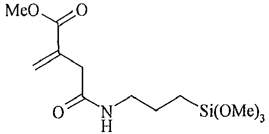
I-8 
I-9 
I-10 
I-11 
I-12 
I-13 
I-14 
I-15 
I-16 
I-17 
I-18 
I-19 
I-20 
I-21 
I-22 
I-23 
I-24 
I-25 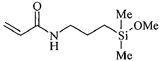
I-26 
I-27 
I-28 
I-29 
I-30 
I-31 
I-32 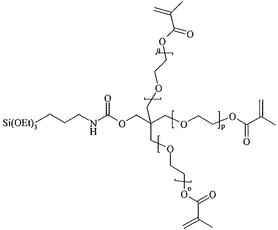
I-33 
I-34 
I-35 - Wherein n, o, p and q in the above structures independently represent an integer from 1 to 40, preferably an integer ranging from 1 to 20, more preferably an integer ranging from 1 to 15. Most preferably, n, o, p and q independently represent 1, 2, 3, 4, 5, 6, 7, 8, 9 or 10.
- The organosilicon compound of Formula (II) is represented by the following formula:
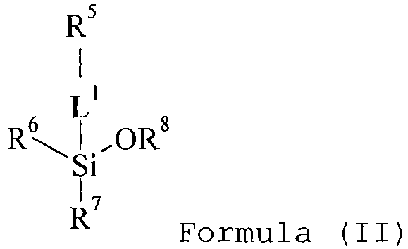
- R5 represents a hydrophylic group selected from a carboxylic acid or a salt thereof, sulphonic acid or a salt thereof, a sulphuric acid or a monoester or a salt thereof, a hydrocarbon group substituted with at least one hydroxyl group, an oligoalkylene oxide group such as an ethylene oxide containing 1 to 120 alkylene oxide units, a quaternary ammonium group or a phosphonium group; or combinations thereof;
- L1 represents a di- or trivalent linking group;
- R6 and R7 independently represent an alkoxy such as a methoxy or ethoxy group, aryloxy or an acyloxy group, an optionally substituted alkyl, cycloalkyl, alkenyl, alkynyl, aryl or heteroaryl group; and
- R8 represents an optionally substituted alkyl, cycloalkyl, alkenyl, alkynyl, aryl, heteroaryl or acyl group.
- Preferably, the hydrophylic group R5 is represented by carboxylic acid, a hydrocarbon group substituted with at least one hydroxyl group, or an ethylene oxide group, or combinations thereof. The ethylene oxide group preferably represents -(O-CH2-CH2)a- with a preferably equal to 1 to 20, more preferably, a is equal to 2 to 10 and most preferably a is equal to 3 to 8.
- More preferably, the hydrophylic group R5 is represented by a hydrocarbon group substituted with at least one hydroxyl group. The hydrocarbon group substituted with at least one hydroxyl group is preferably an alkyl, an aryl or an aralkyl group substituted with at least one hydroxyl group.
- Most preferably, the hydrophylic group R5 is represented by an alkyl group substituted with at least one hydroxyl group.
- The alkyl group substituted with at least one hydroxyl group is preferably selected from 1-hydroxypropyl, 1,2-dihydroxypropyl, 2,2-dimethylhydroxypropyl 5-hydroxypentyl, trimetylolpropane, hydroxyhexyl, hydroxyethyl, polyhydroxybutyl, polyhydroxypentyl or polyhydroxyhexyl.
- R8 preferably represents an optionally substituted alkyl group such as an optionally substituted methyl, ethyl, propyl, isopropyl, butyl, isobutyl or pentyl group. Most preferably, R8 represents a methyl or an ethyl group.
- The optionally substituted acyl group represents for example an alkylcarbonyl group having 1 to 30 carbon atoms, an arylcarbonyl group having 7 to 30 carbon atoms, or a heterocyclic carbonyl group having 4 to 30 carbon atoms in which the heterocyclic group is connected to the carbonyl group with its carbon atom. Suitable examples include an acetyl, pivaloyl, 2-chloroacetyl, stearoyl, benzoyl or a 2-pyridylcarbonyl group.
- Preferably, L1 represents an aliphatic group or an aliphatic group containing a functional group selected from an ether, a thioether, an ester, a ketone, a urethane, an amide, an urea or thio-ureum group.
- More preferably, L1 represents an alkylene represented by -(CH2)k-, a cycloalkylene, an arylene having preferably from 5 to 15 carbon atoms, more preferably from 6 to 10 carbon atoms, such as for example a phenylene group, a xylylene group, a naphthylene group and an anthrylene group, a heteroarylene, -O-(CH2)k-, -S-(CH2)k-, -(CH2)k-O-CO-(CH2)1- -CS-(CH2)k-, -CO-(CH2)k-, -O-CO-NH-, -(CH2)k-CO-NH-, -(CH2)k-NH-CO-, - NR*-CO-NH-, >N-CO-NH-, - NR*-CS-NH-, or combinations thereof and wherein k and 1 independently represent O, 1, or an integer greater than 1 and R* represents hydrogen or an alkyl group such as an methyl, ethyl, propyl, isopropyl, butyl, isobutyl or pentyl group. Preferably R* represents hydrogen or a methyl group. Preferably k and l independently represent an integer selected from to 1 to 20, more preferably k and 1 independently represent an integer selected from 1 to to 10, most preferably an integer selected from 2, 3, 4, 5 or 6. The linking groups may optionally have substituents.
- Preferably, L1 represents a di- or trivalent linking group selected from an alkylene represented by -(CH2)k-, -O-(CH2)k-, -S-(CH2)k-, -NH-CO-, -(CH2)k-NH-CO-, -NR*-CO-NH-, >N-CO-NH- or combinations thereof and wherein k and 1 independently represent O, 1, or an integer greater than 1 and R* represents hydrogen or an alkyl group such as a methyl, ethyl, propyl, isopropyl, butyl, isobutyl or pentyl group. Preferably R* represent hydrogen or a methyl group and preferably k and 1 independently represent an integer equal to 1 to 20, more preferably an integer equal to 2 to 10 and most preferably an integer selected from 2, 3, 4, 5 or 6.
- More preferably the linking group L1 represents -(CH2)k- with k equal to 1, 2, 3, 4 or 5, -CO-NH-, >N-CO-NH- or -NR*-CO-NH- with R* equal to hydrogen, methyl, ethyl; or combinations thereof. Most preferably the linking group L1 represents:
- -CO-NH-aliphatic group-;
- -NH-CO-NH-aliphatic group-;
- -N(CH3)-CO-NH-aliphatic group-; or
- >N-CO-NH-aliphatic group-
- Examples of the optional substituents on the alkyl, cycloalkyl, alkenyl, alkynyl, aryl or heteroaryl group include a halogen atom (e.g., F, Cl, Br or I), a hydroxy group or a cyano group.
- Suitable examples of organosilicon compounds of the general Formula (II) are, without being limited thereto, given in the Table B below.
Table B: Suitable examples of organosilicon compounds of the general Formula (II) 
II-1 
II-2 
II-3 
II-4 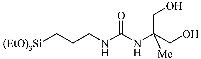
II-5 
II-6 
II-7 
II-8 
II-9 
II-10 
II-11 
II-12 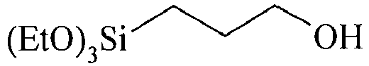
II-13 
II-14 
II-15 
II-16 
II-17 
II-18 
II-19 
II-20 
II-21 
II-22 
II-23 
II-24 
II-25 
II-26 
II-27 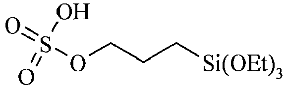
II-28 - In a preferred embodiment, the polysiloxane according to the present invention further contains, besides the organosilicon compound of the general Formula's (I) and (II), a third organosilicon compound containing at least one phosphonic acid group or at least one phosphoric acid group. The organosilicon compound containing at least one phosphonic acid group is preferably represented by the general Formula (III):
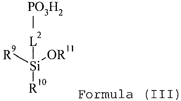
- R9 and R10 independently represent an alkoxy, aryloxy or an acyloxy group, an optionally substituted alkyl, alkenyl, alkynyl, aryl or heteroaryl group;
- L2 represents a divalent linking group selected from an alkylene, a cycloalkylene, an arylene, a heteroarylene, a (poly)alkylene oxide group such as a (poly)ethylene oxide group, -O-(CH2)k-, -S-(CH2)k-, -(CH2)k-O-CO-(CH2)l-, -CS-(CH2)k-, -CO-(CH2)k-, -O-CO-NH-, -(CH2)k-CO-NH-, -NR'-CO-NH-, -NH-CS-NH-, or combinations thereof and wherein R' represents hydrogen or a methyl group, preferably R' represents hydrogen and k and 1 independently represent O, 1, or an integer greater than 1. Preferably k and 1 independently represent an integer selected from to 1 to 20, more preferably an integer selected from to 2 to 10, and most preferably an integer equal to 2, 3, 4, 5 or 6;
- R11 represents an optionally substituted alkyl, alkenyl, alkynyl, aryl, heteroaryl or acyl group.
- Preferably R9 and R10 independently represent an alkoxy group such as a methoxy or ethoxy group; and R11 represents an optionally substituted alkyl group such as a methyl, ethyl, propyl, isopropyl, butyl or pentyl group.
- The optionally substituted acyl group represents for example an alkylcarbonyl group having 1 to 30 carbon atoms, an arylcarbonyl group having 7 to 30 carbon atoms, or a heterocyclic carbonyl group having 4 to 30 carbon atoms in which the heterocyclic group is connected to the carbonyl group with its carbon atom. Suitable examples include an acetyl, pivaloyl, 2-chloroacetyl, stearoyl, benzoyl or a 2-pyridylcarbonyl group.
- Preferably the linking group L2 represents an alkylene, a cycloalkylene, arylene or heteroarylene group or -NH-CO-NH- and combinations thereof. Most preferably, the linking group L2 represents an alkylene represented by -(CH2)m-, a cycloalkylene such as divalent cyclopentyl or cyclohexyl, or -NH-CO-NH-, and combinations thereof, and wherein m represents 1, 2, 3, 4 or 5.
- The linking group L2 preferably does not contain a basic nitrogen atom such as a secundary or a tertiary amino group. Generally, a basic amino group has a pKa value from about 9 to about 12. Specifically polysiloxanes including organosilicon compounds according to Formula (III) containing a linking group including -NRe-CHRf-, -NRe-CH< or >N-CH2- with Re and Rf independently selected from hydrogen, an alkyl, aryl or heteroaryl group, have a bad effect on the lithographic performance and/or result in an inferior image on the plate.
- Examples of the optional substituents on the alkyl, cycloalkyl, alkenyl, alkynyl, acyl, aryl or heteroaryl group include a halogen atom (e.g., F, Cl, Br or I), a hydroxy group or a cyano group.
- Suitable examples of organosilicon compounds of the general Formula (III) are, without being limited thereto, given in the Table C below.
Table C: suitable examples of organosilicon compounds of the general Formula (III) 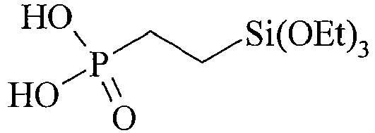
III-1 
III-2 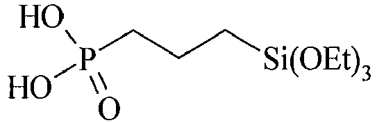
III-3 
III-4 
III-5 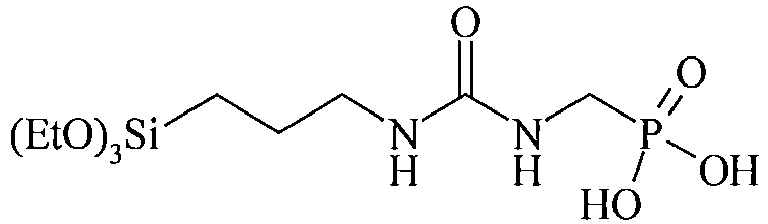
III-6 
III-7 
III-8 
III-9 
III-10 
III-11 
III-12 
III-13 
III-14 
III-15 
III-16 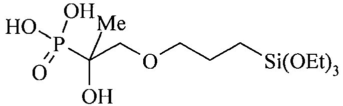
III-17 - The polysiloxanes according to the present invention have a branched or unbranched backbone including alternating silicon and oxygen atoms -Si-O-Si-O-. The polysiloxanes of the present invention can be copolymers including units derived from the organosilicon compound according to Formula (I) and units derived from the organosilicon compound according to Formula (II), and optionally units derived from the organosilicon compound according to Formula (III). They can be random copolymers, alternating copolymers or block copolymers. The term "copolymer" refers to polymers that include two or more different units derived from the organosilicon compounds and the term "polymer" refers to high and low molecular weight polymers including oligomers. A weight average molecular weight (Mw) of the specific polysiloxane according to the present invention can be appropriately set according to the targeted performance design of the lithographic printing plate precursor. The weight average molecular weight is preferably from 2,000 to 1,000,000, more preferably from 2,000 to 500,000, and most preferably from 10,000 to 500,000.
- The preparation of the polysiloxanes of the present invention by reacting organosilicon compounds of Formula (I) and Formula (II) and optionally organosilicon compounds of Formula (III) has, compared to for example addition polymerisations where molecules incorporating double or triple chemical bonds are linked together to form the repeating chain, the major advantage that the obtained reaction products can be immediately used in for example a coating of a printing plate without the need for purification.
- The polysiloxane may be obtained by reacting the organosilicon compound of Formula (I) in an amount ranging between 10 to 50 mol% with the organosilicon compound of Formula (II) in an amount ranging between 20 to 90 mol%; and optionally by further reacting with the organosilicon compound of Formula (III) in an amount ranging between 20 to 90 mol%.
- The lithographic printing plate precursor according to the present invention is negative-working, i.e. after exposure and development the non-exposed areas of the coating are removed from the support and define hydrophilic (non-printing) areas, whereas the exposed coating is not removed from the support and defines oleophilic (printing) areas. The hydrophilic areas are defined by the support which has a hydrophilic surface or is provided with a hydrophilic layer. The hydrophobic areas are defined by the coating, hardened upon exposing, optionally followed by a heating step. Areas having hydrophilic properties means areas having a higher affinity for an aqueous solution than for an oleophilic ink; areas having hydrophobic properties means areas having a higher affinity for an oleophilic ink than for an aqueous solution.
- "Hardened" means that the coating becomes insoluble or non-dispersible for the developing solution and may be achieved through polymerization and/or crosslinking of the photosensitive coating, optionally followed by a heating step to enhance or to speed-up the polymerization and/or crosslinking reaction. In this optionally heating step, hereinafter also referred to as "pre-heat", the plate precursor is heated, preferably at a temperature of about 80°C to 150°C and preferably during a dwell time of about 5 seconds to 1 minute.
- The coating has at least one layer including a photopolymerizable composition, said layer hereinafter also referred to as "photopolymerizable layer". The coating may include an intermediate layer, located between the support and the photopolymerisable layer. The polysiloxane according to the present invention is most preferably present in the photopolymerizable layer. The amount of polysiloxane according to the present invention in the photopolymerizable layer is preferably above 1 %wt, more preferably above 2 %wt and most preferably above 5% wt relative to the total weight of all ingredients in the photopolymerizable layer. Alternatively, the polysiloxane according to the present invention in the photopolymerizable layer is preferably between 1 and 40 %wt, more preferably between 2 %wt and 20 %wt and most preferably between 5 and 15 %wt.
- The level of the polysiloxane in the coating of the printing plate preferably ranges between 0.01 g/m2 to 1 g/m2, more preferably between 0.02 g/m2 to 0.5 g/m2 and most preferably between 0.02 g/m2 to 0.2 g/m2. The thickness of the coating preferably ranges between 0.4 and 10 g/m2, more preferably between 0.5 and 5 g/m2, most preferably between 0.6 and 3 g/m2.
- Alternatively, the polysiloxane may be present in the intermediate layer in an amount of at least 10 wt%, preferably at least 15 wt%, more preferably at least 50 wt%, even more preferably at least 90 wt%, most preferably 100 wt% of the non-volatile components of the composition. The optionally intermediate layer has a coating thickness preferably ranging between 0.001 and 1.5 g/m2, more preferably between 0.003 and 1.0 g/m2, most preferably between 0.005 and 0.7 g/m2. The polysiloxane may also be present in both the photopolymerisable layer and the intermediate layer.
- The photopolymerizable layer includes, besides the polysiloxane according to the present invention, a polymerizable compound, optionally a binder, a polymerization initiator capable of hardening said polymerizable compound in the exposed areas, and optionally a sensitizer capable of absorbing light used in the image-wise exposing step. The photopolymerizable layer has a coating thickness preferably ranging between 0.4 and 5.0 g/m2, more preferably between 0.5 and 3.0 g/m2, most preferably between 0.6 and 2.2 g/m2.
- According to one embodiment of the present invention, the polymerizable compound is a monomer or oligomer including at least one epoxy or vinyl ether functional group and the polymerisation initiator is a Brönsted acid generator capable of generating free acid, optionally in the presence of a sensitizer, upon exposure, hereinafter the Brönsted acid generator is also referred to as "cationic photoinitiator" or "cationic initiator".
- Suitable polyfunctional epoxy monomers include, for example, 3,4-epoxycyclohexylmethyl-3,4-epoxycyclohex-ane carboxylate, bis-(3,4 -epoxycyclohexymethyl) adipate, difunctional bisphenol Aepichlorohydrin epoxy resin and multifunctional epichlorohydrinitetraphenylol ethane epoxy resin.
- Suitable cationic photoinitiators include, for example, triarylsulfonium hexafluoroantimonate, triarylsulfonium hexafluorophosphate, diaryliodonium hexafluoroantimonate, and haloalkyl substituted s-triazine. It is noted that most cationic initiators are also free radical initiators because, in addition to generating Brönsted acid, they also generate free radicals during photo or thermal decomposition.
- According to a more preferred embodiment of the present invention, the polymerizable compound is a polymerizable monomer or oligomer including at least one terminal ethylenic group, hereinafter also referred to as "free-radical polymerizable monomer", and the polymerisation initiator is a compound capable of generating free radicals upon exposure, optionally in the presence of a sensitizer, hereinafter said initiator is referred to as "free radical initiator". The polymerization involves the linking together of the free-radical polymerizable monomers.
- Suitable free-radical polymerizable monomers include, for example, multifunctional (meth)acrylate monomers (such as (meth)acrylate esters of ethylene glycol, trimethylolpropane, pentaerythritol, ethoxylated ethylene glycol and ethoxylated trimethylolpropane, multifunctional urethanated (meth)acrylate, and epoxylated (meth)acrylate), and oligomeric amine diacrylates. The (meth)acrylic monomers may also have other double bond or epoxide group, in addition to (meth)acrylate group. The (meth)acrylate monomers may also contain an acidic (such as carboxylic acid) or basic (such as amine) functionality.
- Any free radical initiator capable of generating free radicals upon exposure directly or in the presence of a sensitizer, is according to this invention a suitable initiator. Suitable free-radical initiators are described in
WO 2005/111727 from page 15 line 17 to page 16 line 11. - In a preferred embodiment of the present invention the photopolymerizable composition comprises a hexaaryl-bisimidazole compound (HABI; dimer of triaryl-imidazole) as polymerization initiator, optionally in combination with further polymerization initiators.
- A procedure for the preparation of hexaarylbisimidazoles is described in
DE 1470 154 and their use in photopolymerizable compositions is documented inEP 24 629 EP 107 792 US 4,410,621 ;EP 215 453 DE 3 211 312 . Preferred derivatives are e.g. 2,4,5,2',4',5'-hexaphenylbisimidazole, 2,2'-bis(2-chlorophenyl)-4,5,4',5'-tetraphenylbisimidazole, 2,2'-bis(2-chlorophenyl)-4,5,4',5'-tetrakis(3-methoxyphenyl)bisimidazole and 2,2'-bis(2-nitrophenyl)-4,5,4',5'-tetraphenylbisimidazole. The amount of the HABI polymerization initiator typically ranges from 0.01 to 30 % by weight, preferably from 0.5 to 20 % by weight, relative to the total weight of the non volatile components of the photopolymerizable composition. - A very high sensitivity can be obtained in the context of the present invention by the combination of an optical brightener as sensitizer and a hexaarylbisimidazole compound as polymerization initiator.
- Suitable classes of polymerization initiators other than hexaarylbisimidazole compounds include aromatic ketones, aromatic onium salts, organic peroxides, thio compounds, ketooxime ester compounds, borate compounds, azinium compounds, metallocene compounds, active ester compounds and compounds having a carbon-halogen bond, but preferably the composition comprises a non-boron comprising polymerization initiator and particularly preferred the polymerization initiator comprises no boron compound. Many specific examples of initiators suitable for the present invention can be found in
EP-A 1 091 247 . Other preferred polymerization initiators are trihalo methyl sulphones. - Preferably hexaarylbisimidazole compounds and/or metallocene compounds are used alone or in combination with other suitable photoinitiators, in particular with aromatic ketones, aromatic onium salts, organic peroxides, thio compounds, ketoxime ester compounds, azinium compounds, active ester compounds or compounds having a carbon halogen bond.
- In a preferred embodiment of the present invention the hexaarylbisimidazole compounds make more than 50 mol%, preferably at least 80 mol% and particularly preferred at least 90 mol% of all the photoinitiators used in the photopolymerizable composition of the present invention.
- According to another embodiment of the present invention, the polymerizable monomer or oligomer may be a combination of a monomer or oligomer comprising at least one epoxy or vinyl ether functional group and a polymerizable ethylenically unsaturated compound having at least one terminal ethylenic group, and the polymerisation initiator may be a combination of a cationic initiator and a free-radical initiator. A monomer or oligomer comprising at least one epoxy or vinyl ether functional group and a polymerizable ethylenically unsaturated compound having at least one terminal ethylenic group, can be the same compound wherein the compound contains both the ethylenic group and the epoxy or vinyl ether group. Examples of such compounds include epoxy functional acrylic monomers, such as glycidyl acrylate. The free radical initiator and the cationic initiator can be the same compound if the compound is capable of generating both free radical and free acid. Examples of such compounds include various onium salts such as diaryliodonium hexafluoroantimonate and s-triazines such as 2,4-bis(trichloromethyl)-6-[(4-ethoxyethylenoxy)-phen-1-yl]-s-triazine which are capable of generating both free radical and free acid, prefarably in the presence of a sensitizer.
- The photopolymerizable layer may also comprise a multifunctional monomer. This monomer contains at least two functional groups selected from an ethylenically unsaturated group and/or an epoxy or vinyl ether group. Particular multifunctional monomers for use in the photopolymer coating are disclosed in
US 6,410,205 ,US 5,049,479 ,EP 1 079 276 ,EP 1 369 232 ,EP 1 369 231 ,EP 1 341 040 ,US 2003/0124460 ,EP 1 241 002 ,EP 1 288 720 and in the reference book including the cited references : Chemistry & Technology UV & EB formulation for coatings, inks & paints - Volume 2 -Prepolymers and Reactive Diluents for UV and EB Curable Formulations by N.S. Allen, M.A. Johnson, P.K.T. Oldring, M.S. Salim - Edited by P.K.T. Oldring - 1991 - ISBN 0 947798102. Particularly preferred are urethane (meth)acrylate multifunctional monomers, which can be used alone or in combination with other (meth)acrylate multifunctional monomers. - The photopolymerizable layer may also comprise a co-initiator. Typically, a co-initiator is used in combination with a free radical initiator and/or a cationic initiator. Suitable coinitiators for use in the photopolymer coating are disclosed in
US 6,410,205 ;US 5,049,479 ;EP 1 079 276 ,EP 1 369 232 ,EP 1 369 231 ,EP 1 341 040 ,US 2003/0124460 ,EP 1 241 002 ,EP 1 288 720 and in the reference book including the cited refences: Chemistry & Technology UV & EB formulation for coatings, inks & paints - Volume 3 -Photoinitiators for Free Radical and Cationic Polymerisation by K.K. Dietliker - Edited by P.K.T. Oldring - 1991 - ISBN 0 947798161. - The photopolymerizable layer may also comprise an inhibitor. Particular inhibitors for use in the photopolymer coating are disclosed in
US 6,410,205 ,EP 1 288 720 andEP 1 749 240 . The photopolymerizable layer may further comprise an adhesion promoting compound. More information on suitable adhesion promoting compounds are described inEP 1 788 434 in [0010]. - Besides the polysiloxane according to the invention, the photopolymerizable layer may include a binder. The binder can be selected from a wide series of organic polymers. Compositions of different binders can also be used. Useful binders are described in
WO2005/052298 page 17 line 21 to page 19 line 30, inEP 152 819 EP 1 043 627 in paragraph [0013]. - The organic polymers used as binders have a typical mean molecular weight Mw between 1000 and 700 000, preferably between 1500 and 350 000. Preferably, the binders have a hydroxyl number between 0 and 750, more preferably between 10 and 500. Even more preferably the hydroxyl number is below 10, most preferably the hydroxyl number is 0. The amount of binder(s) generally ranges from 1 to 60 % by weight, preferably 5 to 50 % by weight, more preferably 10 to 35 % by weight and most preferably 15 to 25 % by weight relative to the total weight of the non-volatile components of the composition.
- In another embodiment the polymeric binder comprises a backbone including pendant groups such as for example a hydrophilic poly(alkylene oxide) segment. The polymeric binder may also include pendant cyano groups attached to the backbone. A combination of such binders may also be employed. Generally the polymeric binder is solid at room temperature, and is typically a non-elastomeric thermoplastic. Generally the polymeric binder is characterized by a number average molecular weight (Mn) in the range from about 500 to 250000, more commonly in the range from about 1000 to 240000 or 1500 to 200000. The polymerizable composition may comprise discrete particles of the polymeric binder. Preferably the discrete particles are particles of the polymeric binder which are suspended in the polymerizable composition. The presence of discrete particles tends to promote developability of the unexposed areas. Specific examples of the polymeric binders according to this embodiment are described in
US 6,899,994 ;US 2004/0260050 ,US 2005/0003285 ,US 2005/0170286 andUS 2005/0123853 . In addition to the polymeric binder of this embodiment the imageable layer may optionally comprise one or more co-binders. Typical co-binders are water-soluble or water-dispersible polymers, such as, cellulose derivatives, polyvinylalcohol, polyacrylic acid poly(meth)acrylic acid, polyvinylpyrrolidone, polylactide, polyvinylphosphonic acid, synthetic co-polymers, such as the co-polymer of an alkoxy polyethylene glycol (meth)acrylate. Specific examples of co-binders are described inUS 2004/0260050 ,US 2005/0003285 andUS 2005/0123853 . Printing plate precursors, the imageable layer of which comprises a binder and optionally a co-binder according this embodiment and described in more detail inUS 2004/0260050 ,US 2005/0003285 andUS 2005/0123853 , optionally comprise a topcoat and an interlayer. - Various surfactants may be added into the photopolymerizable layer to allow or enhance the developability of the precursor; especially developing with a gum solution. Both polymeric and small molecule surfactants can be used. Nonionic surfactants are preferred. Preferred nonionic surfactants are polymers and oligomers containing one or more polyether (such as polyethylene glycol, polypropylene glycol, and copolymer of ethylene glycol and propylene glycol) segments. Examples of preferred nonionic surfactants are block copolymers of propylene glycol and ethylene glycol (also called block copolymer of propylene oxide and ethylene oxide); ethoxylated or propoxylated acrylate oligomers; and polyethoxylated alkylphenols and polyethoxylated fatty alcohols. The nonionic surfactant is preferably added in an amount ranging between 0.1 and 30% by weight of the coating, more preferably between 0.5 and 20% by weight of the coating, and most preferably between 1 and 15% by weight of the coating or between 2 and 8% by weight of the coating.
- Suitable examples of optical brighteners as sensitizers are described in
WO 2005/109103 page 24,line 20 to page 39. The photocurable composition may also comprise other sensitizers. Highly preferred sensitizers are violet light absorbing sensitizers, having an absorption spectrum between 350 nm and 450 nm, preferably between 370 nm and 420 nm, more preferably between 390 nm and 415 nm. Particular preferred sensitizers are disclosed inEP 1 349 006 paragraph [0007] to [0009],EP 1 668 417 andWO 2004/047930 , including the cited references in these patent applications. Other highly preferred sensitizers are infrared light absorbing dyes, having an absorption spectrum between 750 nm and 1300 nm, preferably between 780 nm and 1200 nm, more preferably between 800 nm and 1100 nm. Particular preferred sensitizers are heptamethinecyane dyes, especially the dyes disclosed inEP 1 359 008 paragraph [0030] to [0032]. Other preferred sensitizers are blue, green or red light absorbing sensitizers, having an absorption spectrum between 450 nm and 750 nm. Useful sensitizers can be selected from the sensitizing dyes disclosed inUS 6,410,205 ;US 5,049,479 ;EP 1 079 276 ,EP 1 369 232 ,EP 1 369 231 ,EP 1 341 040 ,US 2003/0124460 ,EP 1 241 002 andEP 1 288 720 . - The photopolymerizable layer or an optional other layer of the coating may also comprise a colorant. After processing, at least part of the colorant remains on the hardened coating areas, and a visible image can be produced on the support by removing the coating, including the colorant, at the non-exposed. The colorant can be a dye or a pigment. Various types of pigments can be used such as organic pigments, inorganic pigments, carbon black, metallic powder pigments and fluorescent pigments. Organic pigments are preferred.
- Specific examples of organic pigments include quinacridone pigments, quinacridonequinone pigments, dioxazine pigments, phthalocyanine pigments, anthrapyrimidine pigments, anthanthrone pigments, indanthrone pigments, flavanthrone pigments, perylene pigments, diketopyrrolopyrrole pigments, perinone pigments, quinophthalone pigments, anthraquinone pigments, thioindigo pigments, benzimidazolone pigments, isoindolinone pigments, azomethine pigments, and azo pigments.
- Specific examples and more detailed information of pigments suitable as colorant in the current invention are described in
EP 2 278 404 in paragraphs [0064] to [0068]. - Typically, the amount of pigment in the coating may be in the range of about 0.005 g/m2 to 2 g/m2, preferably about 0.007 g/m2 to 0.5 g/m2, more preferably about 0.01 g/m2 to 0.2 g/m2, most preferably about 0.01 g/m2 to 0.1 g/m2.
- The colorant can also be a dye. Any known dyes, such as commercially available dyes or dyes described in, for example, "Dye Handbook" (edited by the Organic Synthetic Chemistry Association, published in 1970) which are colored for the human eye, can be used as colorant in the photopolymerizable coating. Specific examples thereof are described in
EP 2 278 404 in paragraph [0070]. - Typically, the amount of dye in the coating may be in the range of about 0.005 g/m2 to 2 g/m2, preferably about 0.007 g/m2 to 0.5 g/m2, more preferably about 0.01 g/m2 to 0.2 g/m2, most preferably about 0.01 g/m2 to 0.1 g/m2.
- The photopolymerizable layer or an optional other layer of the coating may include a printing-out agent, i.e. a compound which is capable of changing the color of the coating upon exposure. After image-wise exposing of the precursor, a visible image can be produced, hereinafter also referred to as "print-out image". The printing-out agent may be a compound as described in
EP-A-1 491 356 paragraph [0116] to [0119] on page 19 and 20, and inUS 2005/8971 EP 1 765 592 from line 1 page 9 to line 27 page 20. More preferred are the IR-dyes as described inEP 1 736 312 from line 32 page 5 to line 9 page 32. The contrast of the image formed after image-wise exposure and processing is defined as the difference between the optical density at the exposed area to the optical density at the non-exposed area, and this contrast is preferably as high as possible. This enables the end-user to establish immediately whether or not the precursor has already been exposed and processed, to distinguish the different color selections and to inspect the quality of the image on the treated plate precursor. The contrast increases with increasing optical density in the exposed area and/or decreasing optical density in the non-exposed areas. The optical density in the exposed area may increase with the amount and extinction coefficient of the colorant remaining in the exposed areas and the intensity of color formed by the printing-out agent. In the non-exposed areas it is preferred that the amount of colorant is as low as possible and that the intensity of color print-out agent is as low as possible. The optical density can be measured in reflectance using an optical densitometer, equipped with several filters (e.g. cyan, magenta, yellow). The difference in optical density at the exposed area and the non-exposed area has preferably a value of at least 0.3, more preferably at least 0.4, most preferably at least 0.5. There is no specific upper limit for the contrast value, but typically the contrast is not higher than 3.0 or even not higher than 2.0. In order to obtain a good visual contrast for a human observer the type of color of the colorant may also be important. Preferred colors for the colorant are cyan or blue colors, i.e. under blue color we understand a color that appears blue for the human eye. - The coating may include on the photopolymerizable layer a top layer which acts as an oxygen barrier layer including water-soluble or water-swellable binders. Preferred binders which can be used in the top layer are polyvinyl alcohol and the polymers disclosed in
WO2005/029190 ,US 6,410,205 andEP 1 288 720 , including the cited references in these patents and patent applications. The most preferred binder for the top layer is polyvinylalcohol. The polyvinylalcohol has preferably a hydrolysis degree ranging between 74 mol % and 99 mol %. The weight average molecular weight of the polyvinylalcohol can be measured by the viscosity of an aqueous solution, 4 % by weight, at 20°C as defined in DIN 53 015, and this viscosity number ranges preferably between 3 and 26, more preferably between 3 and 15, most preferably between 3 and 10. - The coating thickness of the top layer is preferably between 0.25 and 1.75 g/m2, more preferably between 0.25 and 1.3 g/m2, most preferably between 0.25 and 1.0 g/m2. In a more preferred embodiment of the present invention, the top layer has a coating thickness between 0.25 and 1.75 g/m2 and comprises a polyvinylalcohol having a hydrolysis degree ranging between 74 mol % and 99 mol % and a viscosity number as defined above ranging between 3 and 26.
- In a preferred embodiment, the composition and the thickness of the toplayer are optimised in order to obtain a high sensitivity, a good daylight stability and less or no sludge formation during processing. In order to reduce sludge, the toplayer comprises less polyvinylalcohol and polyvinylalcohol with a lower molecular weight, preferably a viscosity number of less than 26, more preferably less than 10 is used and a thickness as low as possible but more than 0.25 g/m2. In order to improve the sensitivity, a good oxygen barrier is desired, using a polyvinylalcohol with a high hydrolysis degree, preferably 88-98%, and a bigger thickness or the toplayer. In order to improve the daylight stability, small penetration of oxygen is desired by a using an oxygen barrier with reduced barrier property for oxygen, preferably by using a smaller thickness of the toplayer and with polyvinylalcohol having a lower hydrolysis degree. Due to a good balance of these elements, an optimised property for the precursor can be obtained.
- The support is preferably a grained and anodized aluminium support, well known in the art. Suitable supports are for example disclosed in
EP 1 843 203 (paragraphs [0066] to [0075]). The grained and anodized aluminium support may be subjected to so-called post-anodic treatments, for example a treatment with polyvinylphosphonic acid or derivatives thereof, a treatment with polyacrylic acid, a treatment with potassium fluorozirconate or a phosphate, a treatment with an alkali metal silicate, or combinations thereof. However, for a precursor optimized to be used without a pre-heat step it is preferred to use a grained and anodized aluminium support without any post-anodic treatment. Besides an aluminium support, a plastic support, for example a polyester support, provided with one or more hydrophilic layers as disclosed in for exampleEP 1 025 992 may also be used. - According to the present invention there is also provided a method for making a negative-working lithographic printing plate comprising the steps of imagewise exposing the printing plate precursor followed by developing the imagewise exposed precursor so that the non exposed areas are dissolved in the developer solution. Optionally, after the imaging step, a heating step is carried out to enhance or to speed-up the polymerization and/or crosslinking reaction.
- The image-wise exposing step can be carried out by a laser. Preferably, the image-wise exposing step is carried out off-press in a plate setter, i.e. an exposure apparatus suitable for image-wise exposing the precursor by a laser such as a laser diode, emitting around 830 nm, a Nd YAG laser, emitting around 1060 nm, a violet laser, emitting around 400 nm, or a gas laser such as Ar laser, or by a digital modulated UV-exposure, e.g. by means of digital mirror devices, or by a conventional exposure in contact with a mask. In a preferred embodiment of the present invention, the precursor is image-wise exposed by a laser emitting IR-light or violet light.
- During the optional heating step the plate precursor is heated, preferably at a temperature of about 80°C to 150°C and preferably during a dwell time of about 5 seconds to 1 minute. The preheating step is preferably carried out in a preheating unit which is preferably provided with heating elements such as IR-lamps, UV-lamps, heated air, a heated metal roll, etc.
- After the exposing step or, when a preheating step is present, after the preheating step, the precursor may be washed in a prewashing station, whereby at least part of the toplayer can be removed by supplying a wash liquid, i.e. water or an aqueous solution, to the coating of the precursor. The washing liquid is preferably water, more preferably tap water. More details concerning the wash step are described in
EP 1 788 434 in [0026]. - After the exposure step, the optional heating step and the optional prewashing step, the precursor is preferably developed by means of immersing the precursor in a developing solution. The developing step is preferably carried out off-press with an aqueous alkaline developing solution or a gum solution. During the development step, the non-exposed areas of the image-recording layer are at least partially removed without essentially removing the exposed areas. The processing liquid can be applied to the plate e.g. by rubbing with an impregnated pad, by dipping, immersing, (spin-)coating, spraying, pouring-on, either by hand or in an automatic processing apparatus. The treatment with a processing liquid may be combined with mechanical rubbing, e.g. by a rotating brush. The developed plate precursor can, if required, be post-treated with rinse water, a suitable correcting agent or preservative as known in the art. During the development step, any water-soluble protective layer present is preferably also removed. The development is preferably carried out at temperatures of 20°C to 40°C in automated processing units as customary in the art. More details concerning the development step can be found in for example
EP 1 614 539 in [42] to [43]. Development in a gumming station comprising at least one gumming unit is for example described inWO 2007057348 on page 40 line 34 to page 44 line 14. - The development step with an aqueous alkaline developing solution may be followed by a rinsing step and/or a gumming step.
- Alternatively, the development step can be carried out by applying a gum solution thereby removing the non-exposed areas of the photopolymerizable layer from the support and gumming the plate in a single step. Preferably, the gumming unit is mechanically coupled to the platesetter by conveying means wherein the precursor is shielded from ambient light. A gum solution is typically an aqueous liquid which comprises one or more surface protective compounds that are capable of protecting the lithographic image of a printing plate against contamination, e.g. by oxidation, fingerprints, fats, oils or dust, or damaging, e.g. by scratches during handling of the plate. Suitable examples of such compounds are film-forming hydrophilic polymers or surfactants. The layer that remains on the plate after treatment with the gum solution preferably comprises between 0.005 and 20 g/m of the surface protective compound, more preferably between 0.010 and 10 g/m, most preferably between 0.020 and 5 g/m. More details concerning the surface protective compounds in the gum solution can be found in
WO 2007/057348 page 9 line 3 to page 11 line 6. - The gum solution preferably has a pH value between 3 and 11, more preferably between 4 and 10.5, even more preferably between 4.5 and 9, and most preferably between 5 and 7. A suitable gum solution is described in for example
EP 1 342 568 in [0008] to [0022]. The viscosity of the gum solution can be adjusted to a value of e.g. between 1.7 and 5 mPa.s, by adding viscosity increasing compounds, such as poly(ethylene oxide) or polyvinylalcohol, e.g. having a molecular weight between 104 and 107. Such compounds can be present in a concentration of 0.01 to 10 g/l. - The gum solution may further comprise an inorganic salt, an anionic surfactant, a wetting agent, a chelate compound, an antiseptic compound, an anti-foaming compound and/or an ink receptivity agent and/or combinations thereof. More details about these additional ingredients are described in
WO 2007/057348 page 11 line 22 to page 14 line 19. - Alternatively, the development step can be carried out on press by mounting the exposed precursor on a plate cylinder of a lithographic printing press and rotating the plate cylinder while feeding dampening liquid and/or ink to the coating.
- After the processing step the plate may be dried in a drying unit. In a preferred embodiment the plate is dried by heating the plate in the drying unit which may contain at least one heating element selected from an IR-lamp, an UV-lamp, a heated metal roller or heated air. In a preferred embodiment of the present invention, the plate is dried with heated air as known in the drying section of a classical developing machine.
- After drying the plate, the plate can optionally be heated in a baking unit. More details concerning the heating in a baking unit can be found in
WO 2007/057348 page 44 line 26 to page 45 line 20. - The printing plate thus obtained can be used for conventional, so-called wet offset printing, in which ink and an aqueous dampening liquid is supplied to the plate. Another suitable printing method uses a so-called single-fluid ink without a dampening liquid. Suitable single-fluid inks have been described in
US 4,045,232 ;US 4,981,517 andUS 6,140,392 . In a most preferred embodiment, the single-fluid ink comprises an ink phase, also called the hydrophobic or oleophilic phase, and a polyol phase as described inWO 00/32705 -

- The alcohol as specified in Table 1 below was added to (3-isocyanatopropyl)-triethoxysilane. Subsequently, dibutyltin dilaurate (DBTDL) was added and the reaction was allowed to continue for the specified time at room temperature. TLC chromatography was used to determine the full conversion of the alcohol.
Table 1: organosilicon compounds according to Formula (I) 
DBTDL Reaction HO-OR12 g time g (mol) * (mol) ml hours I-29 with n=1 9.5 (0.0385) 
5 (0.0385) 0.05 20 I-29 with n=5 4.04 (0.0163) 
5 (0.0163) 0.05 68 I-29 with n=10 2.35 (0.0095) 
5 (0.0095) 0.05 68 I-31 4.61 (0.0202) 
5 (0.0202) 0.15 20 I-22 4.15 (0.0168) 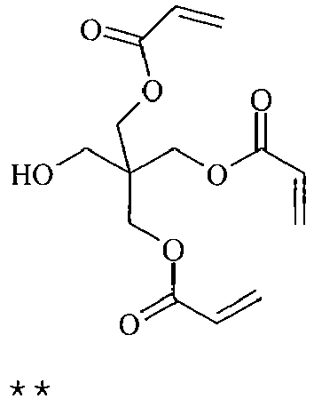
5 (0.0168) 0.15 20 * 95 % purity
** purified by preparative column chromatography before use -

- (3-isocyanatopropyl)-triethoxysilane was dissolved in ethanol. The amine, as specified in Table 2 below was added and the reaction was allowed to continue for the specified time at the specified temperature. TLC chromatography in combination with ninhydrin detection was used to determine the full conversion of the amine.
- The obtained ethanol solutions containing the different organosilicon monomers according to general Formula (II) were further used in the siloxane polymerization without isolating the urea-triethoxysilanes.
Table 2: organosilicon compounds according to Formula (II) 

EtOH Reaction time Reaction temp. g (mol) g (mol)** ml hours °C II-1 2.8 (0.011) 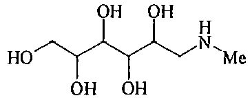
2.1 (0.011) 5 16 reflux II-2 5 (0.019) 
2.2 (0.02) 5 16 65 II-3 5 (0.019) 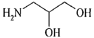
1.79 (0.02) 5 1 RT* II-4 23.6 (0.091) 
8.3 (0.091) 25 16 RT* II-5 5 (0.019) 
2 (0.019) 5 2 RT* II-6 5 (0.019) 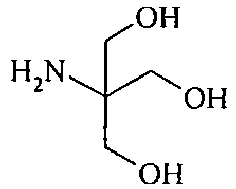
2.3 (0.019) 5 4 70°C *** II-7 5 (0.019) 
1.22 (0.02) 5 2 RT* II-8 5 (0.019) 
1.4 (0.019) 5 2 RT* II-9 5 (0.019) 
1.4 (0.019) 5 2 RT* II-10 5 (0.019) 
1.4 (0.019) 5 2 RT* II-11 5 (0.019) 
2 (0.019) 5 16 RT* II-12 5 (0.019) 
2 (0.019) 5 2 RT* * Room Temperature
** 95 % purity
*** not completely dissolved when stored at room temperature, heating to 70°C is necessary to use the solution in the synthesis of the polysiloxane. -

- 34.8 g (0.106 mol) [2-(triethoxysilyl)ethyl]-phosphonic acid diethyl ester (commercially available from ABCR GmbH & Co.KG) was dissolved in 298 ml methylene chloride. 15.5 ml (18.0 g, 2.5 mol) trimethylsilyl bromide (TMSBr) was added and the reaction was allowed to continue for 90 minutes at room temperature. 85 ml ethanol was added and the reaction mixture was stirred for 30 minutes at room temperature. The reaction mixture was evaporated under reduced pressure and the residue was dried under vacuum until constant weight. The obtained [2-(triethoxysilyl)ethyl]-phosphonic acid (compound III-1) was used directly in the siloxane polymerization without further purification.
- (3-methacryloxypropyl)-trimethoxysilane (Compound I-1, commercially available) and Compound II-1 (see Table 2) were dissolved in water. The reagentia given in Table 3 below were added and the reaction was allowed to continue at room temperature for 24 hours. The aqueous solutions of the polymers were used as such in the printing plate coating solutions.
Table 3: polysiloxanes including the organosilicon compounds according to Formula (I) and Formula (II) 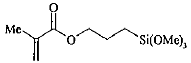

MeSO3H MePO(OH)2 Water Formula (I): compound I-1 Formula (II): compound II-1 g (mmol) g (mmol) ml g (mmol) g (mmol) Silox -01 0.6 (2.4) 5 (11.2) - 0.2 (2.4) 15 Silox -02 0.4 (1.75) 5.4 (12.3) - 0.3 (3.5) 21 Silox -03 0.6 (2.4) 5 (11.2) 0.2 (2.4) - 15 Silox -04 0.4 (1.75) 5.4 (12.3) 0.3 (3.5) - 1 -
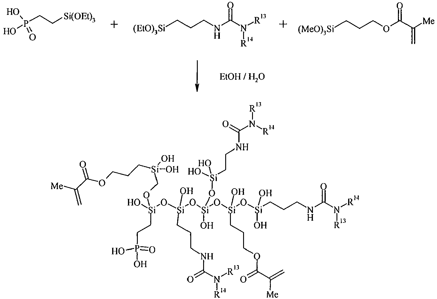
- To a mixture of [2-(triethoxysilyl)ethyl]-phosphonic acid (Compound III-1) and the ethanol solutions of the triethoxysilanes according to Formula II described above (see Table 2), (3-methacryloxypropyl)-triethoxysilane (Compound I-1) was added. Subsequently, the specified amount of water and/or ethanol was added and the mixture was stirred for 15 minutes. The reaction was allowed to continue for 20 hours at room temperature. Table 4 specifies the amount of the reagentia.
- The obtained polymer solution was used directly in the preparation of the coating solutions.
Table 4: polysiloxanes Silox-05 to Silox-28 including organosilicon compounds of Formula (I),Formula (II) and Formula (III). 


EtOH H2O Compound I-1 Compounds according to Formula II* Compound III-1 g (mol) g (mol)** g (mol) ml ml Silox-05 0.60
(0.0024)II-1
4.86
(0.011)0.65
(0.0024)- 10 Silox-06 0.40
(0.0016)II-1
4.86
(0.011)0.84
(0.0031)- 10 Silox-07 1.1
(0.0043)II-2
7.0
(0.02)1.17
(0.0043)- 20 Silox-08 0.72
(0.0029)II-2
7.0
(0.02)1.55
(0.0057)- 20 Silox-09 1.0
(0.0041)II-3
6.4
(0.019)1.12
(0.0041)23.8 1.47 Silox-10 0.67
(0.0027)II-3
6.4
(0.019)1.47
(0.0054)23.8 1.47 Silox-11 4.8
(0.02)II-4
30.8
(0.091)5.44
(0.02)- 90 Silox-12 9.4
(0.038)II-4
30.8
(0.091)6.2
(0.023)- 90 Silox-13 1.0
(0.0041)II-5
6.7
(0.019)1.12
(0.0041)- 20 Silox-14 1.96
(0.0079)II-5
6.7
(0.019)1.28
(0.0047)- 20 Silox-15 1.0
(0.0041)II-6
7.0
(0.019)1.12
(0.0041)- 20 Silox-16 1.96
(0.0079)II-6
7.0
(0.019)1.28
(0.0047)- 20 Silox-17 1.0
(0.0041)II-7
5.85
(0.019)1.12
(0.0041)- 20 Silox-18 1.96
(0.0079)II-7
5.85
(0.019)1.28
(0.0047)- 20 Silox-19 1.0
(0.0041)II-8
6.1
(0.019)1.12
(0.0041)- 20 Silox-20 1.96
(0.0079)II-8
6.1
(0.019)1.28
(0.0047)- 20 Silox-21 1.0
(0.0041)II-9
6.1
(0.019)1.12
(0.0041)- 20 Silox-22 1.96
(0.0079)II-9
6.1
(0.019)1.28
(0.0047)- 20 Silox-23 1.0
(0.0041)II-10
6.1
(0.019)1.12
(0.0041)- 20 Silox-24 1.96
(0.0079)II-10
6.1
(0.019)1.28
(0.0047)- 20 Silox-25 1.0
(0.0041)II-11
6.65
(0.019)1.12
(0.0041)- 20 Silox-26 1.96
(0.0079)II-11
6.65
(0.019)1.28
(0.0047)- 20 Silox-27 1.0
(0.0041)II-12
6.69
(0.019)1.12
(0.0041)- 20 Silox-28 1.96
(0.0079)II-12
6.69
(0.019)1.28
(0.0047)- 20 * see Table 2;
** in 5 ml ethanol - 8.4 g (0.026 mol) [2-(triethoxysilyl)ethyl]-phosphonic acid diethyl ester was dissolved in 70 ml methylene chloride. 9.2 g trimethylsilyl bromide was added and the reaction was allowed to continue for 90 minutes at room temperature. The solvent was removed under reduced pressure and 17.5 ml ethanol was added. The solvent was removed under reduced pressure. The residual oil containing [2-(triethoxysilyl)ethyl]-phosphonic acid (compound III-1) was dissolved in 17.5 ml ethanol. 2.5 g (0.012 mol) tetraethoxysilane and 3 g (0.012 mol) (3-methacryloxypropyl)-triethoxysilane (compound I-1) were dissolved in the ethanol solution and 20 ml water was added. The reaction was allowed to continue for 48 hours at room temperature and polysiloxane Silox-29 is obtained. The polymer solution was used as such in the printing plate coating solutions.
-

- 1.6 g (19 mmol) of morpholine was dissolved in 5 ml ethanol. 4.9 g (19 mmol) of 3-isocyanatopropyl-triethoxysilane was added dropwise. The reaction temperature rose to 45°C upon addition. The reaction was allowed to continue at room temperature for an additional two hours. The solution containing COMPSIL-1 was used as such for further polymerisation.
- 1.18 g (4.4 mmol) of [2-(triethoxysilyl)ethyl-]-phosphonic acid (compound III-1) was dissolved in the ethanol solution of COMPSIL-1 described above. 1 g (4.1 mmol) of (3-methacryloxypropyl)-trimethoxysilane was added, followed by the addition of 20 ml water. The temperature rose to 30°C upon the addition of water. The reaction was allowed to coninue at room temperature for 20 hours. 20 ml ethanol was added and the reaction mixture was filtered over a 0.45µm filter. The reaction mixture was used as such in the printing plate precursor preparation.
-

- 1.6 g (19 mmol) of 2-ethoxy-ethylamine was dissolved in 5 ml ethanol. 4.9 g (19 mmol) of 3-isocyanatopropyl-triethoxysilane was added dropwise. The reaction temperature rose to 30°C upon addition. The reaction was allowed to continue at room temperature for an additional two hours. The solution containing COMPSIL-2 was used as such for further polymerisation.
- 1.18 g (4.4 mmol) of [2-(triethoxysilyl)ethyl-]-phosphonic acid (compound III-1) was dissolved in the ethanol solution of COMPSIL-2 described above. 1 g (4.1 mmol) of (3-methacryloxypropyl)-trimethoxysilane was added, followed by the addition of 20 ml water. The temperature rose to 34°C upon the addition of water. The reaction was allowed to coninue at room temperature for 20 hours. 12 ml ethanol was added and the reaction mixture was filtered over a 0.45µm filter. The reaction mixture was used as such in the printing plate precursor preparation.
Table 5:comparative polysiloxanes Silox-29, Silox-30 and Silox-31 First unit Second unit Third unit Silox-29 
- 
compound I-1 Compound III-1 Silox-30 


compound I-1 Compound III-1 Comparative compound COMPSIL-1 Silox-31 


compound I-1 Comparative compound COMPSIL-2 Compound III-1 -

- The ethanol solution of the triethoxysilanes according to Formula II (compounds II-2 or II-7; see Table 2) was added to [2-(triethoxysilyl)ethyl]-phosphonic acid (Compound III-1). The mixture was stirred for 20 minutes. Subsequently, the mixture was added to a compound according to Formula I (Table 1 above). The mixture was stirred for 30 minutes. Subsequently, 20 ml of water was added and the reaction was allowed to continue for 20 hours at room temperature. Table 6 specifies the amount of the reagentia. The obtained polymer solution was used directly in the preparation of the coating solutions.
Table 6: polysiloxanes Silox-32 to Silox-41 including organosilicon compounds of Formula (I), Formula (II) and Formula (III) 


Compound according to Formula I* Compound according to Formula II** Compound III-1 g (mol) g (mol)*** g (mol) Silox- I-29 with n=1 II-7 32 1.55 (0.0041) 5.85 (0.019) 1.12 (0.0041) Silox- I-29 with n=1 II-2 33 1.55 (0.0041) 6.69 (0.019) 1.12 (0.0041) Silox- I-29 with n=5 II-7 34 2.27 (0.0041) 5.85 (0.019) 1.12 (0.0041) Silox- I-29 with n=5 II-2 35 2.27 (0.0041) 6.69 (0.019) 1.12 (0.0041) Silox- I-29 with n=10 II-7 36 3.17 (0.0041) 5.85 (0.019) 1.12 (0.0041) Silox- I-29 with n=10 II-2 37 3.17 (0.0041) 6.69 (0.019) 1.12 (0.0041) Silox- I-31 II-7 38 2.24 (0.0041) 5.85 (0.019) 1.12 (0.0041) Silox- I-31 II-2 39 2.24 (0.0041) 6.69 (0.019) 1.12 (0.0041) Silox- I-22 II-7 40 1.95 (0.0041) 5.85 (0.019) 1.12 (0.0041) Silox- I-22 II-2 41 1.95 (0.0041) 6.69 (0.019) 1.12 (0.0041) * see Table 1;
** see Table 2;
*** in 5 ml ethanol. - A 0.3 mm thick aluminium foil was degreased by spraying with an aqueous solution containing 26 g/l NaOH at 65°C for 2 seconds and rinsed with demineralised water for 1.5 seconds. The foil was then electrochemically grained during 10 seconds using an alternating current in an aqueous solution containing 15 g/l HCl, 15 g/l SO4 2- ions and 5 g/l Al3+ ions at a temperature of 37°C and a current density of about 100 A/dm2. Afterwards, the aluminium foil was then desmutted by etching with an aqueous solution containing 5.5 g/l of NaOH at 36°C for 2 seconds and rinsed with demineralised water for 2 seconds. The foil was subsequently subjected to anodic oxidation during 15 seconds in an aqueous solution containing 145 g/l of sulfuric acid at a temperature of 50°C and a current density of 17 A/dm2, then washed with demineralised water for 11 seconds and dried at 120°C for 5 seconds.
- The support S-01 thus obtained was characterised by a surface roughness Ra of 0.35-0.4 µm (measured with interferometer NT1100) and had an anodic weight of 3.0 g/m2.
- The printing plate precursors PPP-01 to PPP-18 were produced by coating onto the above described support S-01 the components as defined in Table 7 dissolved in a mixture of 40% by volume of MEK and 60% by volume of Dowanol PM (1-methoxy-2-propanol, commercially available from DOW CHEMICAL Company). The coating solution was applied at a wet coating thickness of 20 µm and then dried at 120°C for 1 minute in a circulation oven.
Table 7: composition and dry coating weight of the photopolymerisable layer PL-01. INGREDIENT PL-01 (g/m2) Fluomix (1) 0.052 Binder-01 (2) 0.1 FST 426R (3) 0.225 SR368 (4) 0.225 Tegoglide 410 (5) 0.001 HABI (6) 0.078 Pig-disp-01 (7) 0.120 MBT (8) 0.021 Polysiloxane (9) 0.1 Dry coating weight 0.922 (1) Fluomix is a violet sensitizer mixture consisting of the following compounds: 


(2) Binder-1 represents Gohsemfimer L-5407™, a 36% hydrolyzed polyvinyl acetate commercially available from NIPPON GOHSEI;
(3) FST 426R™ is a reaction product from 1 mole of 2,2,4-trimethyl-hexamethylenediisocyanate and 2 moles of hydroxyethyl-methacrylate;
(4) SR368™ is tris (2-hydroxy ethyl) isocyanurate triacrylate commercially available from Sartomer;
(5) Tegoglide 410™ is a surfactant commercially available from Evonik Tego Chemie GmbH;
(6) HABI is 2,2'-bis(o-chlorophenyl)-4,4',5,5'-tetraphenylbiimidazole commercially available from SUMITOMO;
(7) Pig-disp-01 contains in a 50/50 ratio Hostaperm Blue P-BFS™ commercially available from Clariant and Disperbyk 182 commercially available from BYK Chemie GmbH.;
(8) MBT is 2-mercaptobenzthiazole;
(9) polysiloxane of Tables 3, 4 and 5. - On top of the photosensitive layer, a solution in water with the composition as defined in Table 8 was coated (40 µm) on the printing plate precursors PPP-01 to PPP-18 and dried at 110°C for 2 minutes. The so-formed protective top layer OC-1 has a dry thickness or dry coating weight of 1.25 g/m2.
Table 8: Composition of the top layer solution OC-01. INGREDIENT OC-01 (g) Mowiol 4-88 (1) 19.1 Mowiol 8-88 (1) 5.84 Luviskol K30 (2) 5.95 Acticide LA1206 (3) 0.06 Lutensol A8 (4) 0.30 Water 969 (1) Mowiol 4-88™ and Mowiol 8-88™ are partially hydrolyzed polyvinylalcohols commercially available from Kuraray;
(2) Luviskol K30™ is polyvinylpyrrolidone homopolymer commercially available from BASF;
(3) Acticide LA1206™ is a biocide commercially available from Thor;
(4) Lutensol A8™ is a surface active agent commercially available from BASF. - Each printing plate precursor PPP-01 to PPP-18 was cut into two parts. The first part is further referred to as the "fresh" printing plate precursor. The second part of each precursor was artificially aged by storing it during 5 days in a cabinet conditioned at 57°C and 34% R.H. This second part is further referred to the "aged" printing plate precursor. After ageing the "aged" printing plate precursor was allowed to cool down to room temperature before imaging.
- Both the "fresh" and "aged" printing plate precursors were subsequently imaged either with a Galileo VXT platesetter at 2400 dpi (200 lpi Agfa Balanced Screening (ABS)) or a Polaris VXT platesetter at 1270 dpi (110 lpi Agfa Balanced Screening (ABS))(both commercially available from Agfa Graphics NV and equipped with a 405 nm violet laser diode) and this at energy densities between 50 and 90 µJ/cm2.
- After imaging, both the "fresh" and "aged" printing plate precursors were subjected to processing with Gum-1 in a CRF45 processor™ (dwell time 30 s, at 21°C), available from Agfa Graphics, to remove the coating in the non-image areas from the support. Printing plates PP-01 to PP-18 were obtained.
- Gum-1 is a solution prepared as follow:
- To 650 ml demineralised water
- 67 ml of Emulsogen TS 160™, a non-ionic surfactant (commercially available from Clariant);
- 21.21 ml sodium n-octyl sulfate commercially available from Henkel as a 42 wt% solution in water;
- 25 g of potato dextrine Avedex 37 commercially available from Avebe BA;
- 3.01 g of orthophosphoric acid;
- 7 g of triethanolamine and
- 9.5 ml phenoxypropanol commercially available from BASF were added under stirring and demineralised water was further added to make 1000 ml.
- The pH is 7 at room temperature.
- The density of the non-image areas (Dmin) of the plates after imaging and processing was determined and is a measure of the stain resistance of the plate. The density is measured using a GretagMacBeth DC19 densitometer (commercially available from GretagMacbeth AG, cyan filter setting, zeroed on a non-coated piece of aluminium substrate AS-01). A Dmin value higher than 0.05 is unacceptable.
- The results of the Dmin evaluation obtained for the "aged" printing plates are given in Table 9.
Table 9: Dmin results Printing plate D min "aged" samples PP-01 (inv) Silox-01 0.01 PP-02 (inv) Silox-02 0.01 PP-03 (inv) Silox-03 0.01 PP-04 (inv) Silox-04 0.01 PP-05 (inv) Silox-05 0.01 PP-06 (inv) Silox-06 0.01 PP-07 (inv) Silox-07 0.01 PP-08 (inv) Silox-09 0.05 PP-09 (inv) Silox-11 0.01 PP-10 (inv) Silox-13 0.01 PP-11 (inv) Silox-15 0.04 PP-12 (inv) Silox-17 0.02 PP-13 (inv) Silox-19 0.05 PP-14 (inv) Silox-21 0.02 PP-15 (inv) Silox-27 0.01 PP-16 (comp) Silox-29 0.1 PP-17 (Comp) Silox-30 0.37 PP-18 (Comp) Silox-31 0.1 - The results show that the Dmin results of the "aged" printing plates containing the polysiloxane according to the present invention result in printing plates with an acceptable Dmin after imaging and development (i.e. no stain in the non-image areas). When the comparative polysiloxane is present, a non-acceptable stain occurs in the non-image areas after imaging and development.
- After processing, the "fresh" printing plates PP-01 to PP-18 were mounted on a Heidelberg GTO 46™ printing press (available form Heidelberg). Each print job was started using K+E Novavit 800 Skinnex ink™ (trademark of BASF Druckfarben GmbH)and 2 wt% Prima FS404™ (trademark of Agfa Graphics) in water as fountain solution. A compressible blanket was used and printing was performed on non-coated offset paper. Each plate was printed up to 250 sheets. The 250th printed sheet was evaluated both with regard to toning (unwanted ink acceptance in the non-image parts) and to the rendering of the small dots at 110 or 200 lpi ABS (Agfa Balanced screening, commercially available from Agfa Graphics N.V.), depending on the platesetter used.
- The results of the evaluation of the printed sheets (toning, rendering of the small dots) is given in Table 10. The rendering of the small dots on the printed sheet was evaluated with a 50x magnification hand microscope. Smallest dot is defined as the smallest % dot visible upon 8 X magnification. The lower the number, the better the image sensitivity of the printing plate.
Table 10: Results for the Printing plates PP-01 to PP-18. Printing plate Smallest dots rendered on paper (%) Clean-out (printed sheet)** PP-01 (inv) 5 0 PP-02 (inv) 3 0 PP-03 (inv) 5 0 PP-04 (inv) 5 0 PP-05 (inv) 3 0 PP-06 (inv) 3 0 PP-07 (inv) 2 1 PP-08 (inv) 1 1 PP-09 (inv) 4 0 PP-10 (inv) 1 1 PP-11 (inv) 3 0 PP-12 (inv) 1 1 PP-13 (inv) 2 1 PP-14 (inv) 1 1 PP-15 (inv) 2 0 PP-16 (comp) 2 3 PP-17 (comp) * 4 PP-18 (comp) * 4 * : cannot properly be evaluated (due to bad clean-out)
** : 0 = good, very slight stain;
1 = slight stain, some stain, slight toning, slightly speckled toning;
2 = stain, speckled toning;
3 = much stain;
4 = black pages. - The results in Table 10 show that the invention printing plates have an excellent laser sensitivity (smallest %dot values ranging between 1 and 5). In addition, the results of Table 10 demonstrate that the presence of the siloxanes according to the present invention in the printing plate results in an excellent clean-out behaviour.
- The printing plate precursors PPP-19 to PPP-22 were prepared by coating onto the above described support S-01 (see Example 1) the components as defined in Table 11 dissolved in a mixture of 40% by volume of MEK and 60% by volume of Dowanol PM (1-methoxy-2-propanol, commercially available from DOW CHEMICAL Company). The coating solution was applied at a wet coating thickness of 20 µm and then dried at 120°C for 1 minute in a circulation oven.
Table 11: Composition and dry coating weight of the photopolymerisable layer PL-02. INGREDIENT PL-02 (g/m2) IR dye (1) 0.024 Binder-02 (2) 0.150 FST 426R (3) 0.281 CN-UVE 151M (4) 0.281 Tegoglide 410 (5) 0.0015 p-OH-TBMPS (6) 0.06 Pig-disp-01 (7) 0.120 Siloxane (8) 0.100 Dry coating weight 1.0175 (1) IR dye is an infrared absorbing dye having the following structure : 
(2) Binder-02 represents Mowital B30T™, a vinyl butyral polymer commercially available from Sekisui;
(3) See Table 7;
(4) CN-UVE 151M™ is an epoxy diacrylate monomer commercially available from Sartomer;
(5) See Table 7;
(6) p-OH-TBMPS is 4-hydroxyphenyl-tribromomethyl-sulfone
(7) see Table 7;
(8) polysiloxane as indicated in Tables 4 and 12. - On top of the photosensitive layer the protective top layer OC-1 (see Example 1) was coated on the printing plate precursors PPP-19 to PPP-22 and dried at 110°C for 2 minutes. The so-formed protective top layer OC-1 has a dry thickness or dry coating weight of 1.25 g/m2.
- Each printing plate precursor PPP-19 to PPP-22 was cut into two parts. The first part is further referred to as the "fresh" printing plate precursor. The second part of each precursor was artificially aged in the same way as in Example 1.
- Both the "fresh" and "aged" printing plate precursors were subsequently imaged at 2400 dpi with a Creo 3244T™ thermal platesetter (200 lpi Agfa Balanced Screening (ABS)), commercially available from Kodak and equipped with a 830 nm IR laser diode, at energy densities between 70 and 130 mJ/cm2.
- After imaging, both the "fresh" and "aged" printing plate precursors were subjected to processing with Gum-2 in a CRF45 processor™ (dwell time 30 s, at 21°C), available from Agfa Graphics, to remove the coating on the non-image areas from the support. Printing plates PP-19 to PP-22 were obtained.
- Gum-2 is a solution prepared as follow:
- To 650 ml demineralised water
- 67 ml of Emulsogen TS 160™, a non-ionic surfactant commercially available from Clariant;
- 21.21 ml sodium n-octyl sulfate commercially available from Henkel as a 42% solution in water;
- 70 g of potato dextrine Avedex 37 commercially available Avebe BA;
- 5 g of potassium hydrogen phosphate;
- 2.35 g of sodium hydroxide (50 wt% aqueous solution) and
- 9.5 ml phenoxypropanol commercially available from BASF were added under stirring and demineralised water was further added to make 1000 ml.
- The pH is 7 at room temperature.
- The density of the non-image areas (Dmin) of the plates after imaging and processing was determined and is a measure of the stain resistance of the plate. The density is measured using a GretagMacBeth DC19 densitometer (commercially available from GretagMacbeth AG, cyan filter setting, zeroed on a non-coated piece of aluminium substrate AS-01). A Dmin value higher than 0.05 is unacceptable.
- The results of the Dmin evaluation obtained for the "aged" printing plates are given in Table 12.
Table 12: Dmin results Printing plate D min "aged sample" PP-19 (inv) Silox-17 0.03 PP-20 (inv) Silox-19 0.04 PP-21 (inv) Silox-27 0.04 PP-22 (comp) Silox-42** * * cannot be evaluated due to bad clean-out/no image formation;
** comparative polysiloxane described and synthesized inUS 7,524,613 in column 13 and 14 (polysiloxane III-a) and including the following organosilicon compound:
- The results in Table 12 show that the Dmin results of the "aged" printing plates containing the polysiloxane according to the present invention result in printing plates with an acceptable Dmin after imaging and development (i.e. no stain in the non-image areas). When the comparative polysiloxane is present, no image was formed.
- The "fresh" printing plates were used in the printing process in the same way as in Example 1. Also the evaluation of the resulting 250th printed sheet was performed in the same way.
- The results of the evaluation of the printed sheets (toning and rendering of the small dots) is given in Table 13. The rendering of the small dots on the printed sheet was evaluated with a 50x magnification hand microscope. Smallest dot is defined as the smallest % dot visible upon 8 X magnification. The lower the number, the more sensitive the printing plate.
Table 13: Printing results for the printing plates PP-19 to PP-22 Printing plate precursor Smallest dots rendered on paper Clean-out (printed sheet)** PP-19 (inv) 3 0 PP-20 (inv) 5 0 PP-21 (inv) 5 0 PP-22 (comp) * 4 * : cannot properly be evaluated (due to bad clean-out, no image formation)
** : 0 = good, very slight stain
1 = slight stain, slightly speckled toning
2 = stain, speckled toning
3 = much stain
4 = black pages - The results in Table 13 show that the invention printing plates have an excellent highlight rendering: smallest %dot values ranging between 1 and 5. In addition, the results of Table 13 demonstrate that the presence of the siloxanes according to the present invention in the printing plate results in an excellent clean-out behaviour.
- The inventive printing plate precursors PPP-23 to PPP-34 and comparative printing plate precursor PPP-35 were produced by respectively coating onto the above described support S-01 (see Example 1) PL-03 and PL-04 (components as defined in Table 14) dissolved in a mixture of 40% by volume of MEK and 60% by volume of Dowanol PM (1-methoxy-2-propanol, commercially available from DOW CHEMICAL Company). The coating solution was applied at a wet coating thickness of 20 µm and then dried at 120°C for 1 minute in a circulation oven.
Table 14: Composition and dry coating weight of the photopolymerisable layer PL-03 and PL-04. INGREDIENT PL-03 PL-04 (g/m2) Fluomix (1) 0.050 0.050 Poly(vinyl acetate) (2) 0.150 0.150 FST 426R (3) 0.600 0.600 Tegoglide 410 (4) 0.0015 0.0015 HABI (5) 0.075 0.075 Pig-disp-01 (6) 0.120 0.120 MBT (7) 0.020 0.020 Polysiloxane (8) 0.050 - Albritect CP30 (9) - 0.024 Sipomer PAM 100 (10) - 0.13 Dry coating weight 1.0665 1.1705 (1, 3-7) See Table 7;
(2) Mw on average 500.000, commercially available from Aldrich, (8) see Tables 4 and 6;
(9) copolymer of vinyl phosphonic acid and acrylic acid, commercially available from RHODIA;
(10) phosphate functionalized speciality methacrylate monomer; 50 wt % solution in Dowanol PM, commercially available from RHODIA as an undiluted liquid. - On top of the photosensitive layer the protective top layer OC-1 (see Example 1) was coated on the printing plate precursors PPP-23 to PPP-35 and dried at 110°C for 2 minutes. The so-formed protective top layer OC-1 has a dry thickness or dry coating weight of 1.25 g/m2.
- The printing plate precursors PPP-23 to PPP-35 were subsequently imaged either with a Galileo VXT platesetter at 2400 dpi (200 lpi Agfa Balanced Screening (ABS)) or a Polaris VXT platesetter at 1270 dpi (110 lpi Agfa Balanced Screening (ABS))(both commercially available from Agfa Graphics NV and equipped with a 405 nm violet laser diode) and this at energy densities between 40 and 90 µJ/cm2.
- After imaging, the obtained printing plate precursors were subjected to processing with the gum solution VIOLET CF GUM-NP™ commercially available from Agfa-Gevaert NV in a CRF45 processor™ (dwell time 30 s, at 21°C), available from Agfa Graphics, to remove the coating in the non-image areas from the support. Printing plates PP-23 to PP-35 were obtained.
- Exposure was carried out on an Agfa Polaris X violet plate setter™ at 1270 dpi through an UGRA Step Wedge (wedge constant of 0,15). The sensitivity, i.e. right exposure, was determined for each printing plate precursor. The sensitivity is defined as the exposure energy density (in µJ/cm2) needed to obtain an optical density >97% of the maximum optical density that can be obtained on this plate after processing on the first three wedge steps.
- The sensitivity results obtained for PP-23 to PP-35 are given in Table 15.
Table 15: Sensitivity results of PP-23 to PP-35. Printing plate siloxane Including organosilicon comp. according to Formula I Comparative compounds Sensitivity (µJ/cm2)* including -(O-CH2-CH2)n- Amount of unsaturated bonds PP-23 Inv. Silox-07 n=0 1 - 76 PP-24 Inv. Silox-17 n=0 1 - 71 PP-25 Inv. Silox-32 n=1 1 - 76 PP-26 Inv. Silox-33 n=1 1 - 76 PP-27 Inv. Silox-34 n=5 1 - 67 PP-28 Inv. Silox-35 n=5 1 - 67 PP-29 Inv. Silox-36 n=10 1 - 57 PP-30 Inv. Silox-37 n=10 1 - 57 PP-31 Inv. Silox-38 n=0 2 - 62 PP-32 Inv. Silox-39 n=0 2 - 62 PP-33 Inv. Silox-40 n=0 3 - 48 PP-34 Inv. Silox-41 n=0 3 - 57 PP-35 Comp. - - - Albritect CP30 and Sipomer PAM 100 150 - The results in Table 15 show that the invention printing plates PP-23 to PP-34 including a siloxane according to the present invention have a significantly improved laser sensitivity compared to the comparative printing plate PP-35.
- The results show that the spacer length (in terms of amount of -(O-CH2-CH2)n-) and/or the amount of double bonds in the organosilicon compound according to Formula I included in the siloxane compound, have a significant effect on the sensitivity of the printing plate: longer spacers and/or more double bonds in the siloxane compound significantly improve the sensitivity of the printing plate.
- The inventive printing plate precursors PPP-36 to PPP-46 and comparative printing plate precursor PPP-47 were produced by respectively coating onto the above described support S-01 (see Example 1) PL-05 and PL-06 (components as defined in Table 16) dissolved in a mixture of 40% by volume of MEK and 60% by volume of Dowanol PM (1-methoxy-2-propanol, commercially available from DOW CHEMICAL Company). The coating solution was applied at a wet coating thickness of 20 µm and then dried at 120°C for 1 minute in a circulation oven.
Table 16: Composition and dry coating weight of the photopolymerisable layers PL-05 and PL-06. INGREDIENT (g/m2) PL-05 PL-06 IR dye (1) 0.022 0.022 Poly(vinyl acetate) (2) 0.150 0.150 FST 426R (3) 0.600 0.600 Tegoglide 410 (4) 0.0015 0.0015 p-OH-TBMPS (5) 0.060 0.060 Pig-disp-01 (6) 0.120 0.120 Siloxane (7) 0.050 - Albritect CP30 (8) - 0.024 Sipomer PAM100 (9) - 0.13 Dry coating weight 1.0035 1.1075 (1 and 3 to 6) see Table 11;
(7) see Tables 4 and 6;
(2), (8) and (9) see Table 14. - On top of the photosensitive layer the protective top layer OC-1 (see Example 1) was coated on the printing plate precursors PPP-36 to PPP-48 and dried at 110°C for 2 minutes. The so-formed protective top layer OC-1 has a dry thickness or dry coating weight of 1.25 g/m2.
- The printing plate precursors were subsequently imaged at 2400 dpi with a Creo 3244T thermal platesetter™ (200 lpi Agfa Balanced Screening (ABS)), commercially available from Kodak and equipped with a 830 nm IR laser diode, at energy densities between 70 and 150 mJ/cm2.
- After imaging the printing plate precursors were subjected to processing with the gum solution VIOLET CF GUM-NP™ commercially available from Agfa-Gevaert NV in a CRF45 processor™ (dwell time 30 s, at 21°C), available from Agfa Graphics, to remove the coating in the non-image areas from the support. Printing plates PP-36 to PP-48 were obtained.
- Exposure was carried out on a Creo 3244T thermal platesetter™ at 2400 dpi. The sensitivity, i.e. right exposure, was determined for each printing plate precursor. The sensitivity is defined as the exposure energy density (in mJ/cm2) needed to obtain (after processing) a dotgain value of 1 to 1.5% in a dot pattern with a (theoretical) dot coverage of 30% (at 200 lpi).
- A sensitivity value of 150 mJ/cm2 was obtained for the inventive printing plates PP-35 to PP-46 and 250 mJ/cm2 for the comparative printing plate PP-47. These results indicate that the siloxanes according to the present invention result in printing plates with a significant improved sensitivity compared to the comparative printing plate.
- A test field consisting of several patterns such as a uniform dot pattern with a (theoretical) dot coverage of 40% (at 200lpi) was exposed on each printing plate at the right exposure in order to evaluate the dot loss on the printed sheet during printing. Printing was conducted on a Heidelberg GTO-46 sheetfed press™ (available from Heidelberger Druckmaschinen AG) up to 30000 impressions, using a compressible rubber blanket Conti-Air Entropia-HC ContiTech™ and K + E Novavit 800 Skinnex ink™ (trademark of BASF) to which 0.5 wt% of 15 micron CaCO3 particles K4 Plus obtained from Manroland Benelux NV and 2% Agfa Prima FS404 fountain solution™ additive (trademark of Agfa Graphics) was added. The dotloss % is a measure for the abrasive wear of the plate during printing and is defined as the difference between the dot coverage of the 40% pattern on printed page 1000 and the dot coverage of the 40% pattern on page 30000, divided by the dot coverage on page 1000. A high value of dotsize loss after the test, reflects a high occurrence of abrasive wear on the plate during the test.
- The presslife test results obtained for the inventive pinting plates PP-36 to PP-46 and comparative printing plate PP-47 are given in Table 17.
Table 17: presslife results of PP-36 to PP-47. Printing plate Siloxane including organosilicon compound II-2 or II-7 and organosilicon compound according to Formula I including -(O-CH2-CH2)n- Amount of unsaturated bonds Comp. compound Abrasive wear* PP-36 Silox -07 II-2 n=0 1 - 54 PP-37 Silox -33 II-2 n=1 1 - 44 PP-38 Silox -35 II-2 n=5 1 - 18 PP-39 Silox -37 II-2 n=10 1 - 22 PP-40 Silox -39 II-2 n=0 2 - 26 PP-41 Silox -41 II-2 n=0 3 - 40 PP-42 Silox -17 II-7 n=0 1 - 20 PP-43 Silox -32 II-7 n=1 1 - 14 PP-44 Silox -34 II-7 n=5 1 - 11 PP-45 Silox -36 II-7 n=10 1 - 9 PP-46 Silox -38 II-7 n=0 2 - 13 PP-47 - - - - Albitrect CP30 and Sipomer PAM 100 55 * Dotsize loss after accelerated presslife test (%): the higher the value the more abrasive wear during printing. - The presslife test results of the printing plates including the siloxane compounds according to the present invention are significantly improved compared to the presslife test results of the reference printing plate including the comparative compounds. The results further show that siloxane compounds including an organosilicon compound according to Formula I with a longer spacer length in terms of -(O-CH2-CH2)n-, result in plates which are less sensitive to abrasive wear: PP-36, PP-37, PP-38 and PP-39, and, PP-42, PP-43, PP-44 and PP-45. Furthermore, siloxane compounds including an organosilicon compound according to Formula I including more double bonds, result in plates which are less sensitive to abrasive wear: PP-36 compared to PP-39 and PP-41, and PP-42 compared to PP-46.
Claims (15)
- A negative-working lithographic printing plate precursor comprising a support having a hydrophilic surface or which is provided with a hydrophilic layer, a coating on the support including a photopolymerizable layer and optionally an intermediate layer between the photopolymerizable layer and the support, wherein the coating further comprises a polysiloxane, said polysiloxane being present in the photopolymerizable layer and/or in the optional intermediate layer, characterized in that the polysiloxane is obtainable by reacting at least one organosilicon compound represented by the general Formula (I) and at least one organosilicon compound represented by the general Formula (II):
 R1 represents a group including at least one free radical polymerisable group,R2, R3, R6 and R7 independently represent an alkoxy, aryloxy or an acyloxy group, an optionally substituted alkyl, cycloalkyl, alkenyl, alkynyl, aryl or heteroaryl group;R4 and R8 independently represent an optionally substituted alkyl, cycloalkyl, alkenyl, alkynyl, aryl, heteroaryl group or acyl group;R5 represents a hydrophilic group selected from a carboxylic acid or a salt thereof, a sulphonic acid or a salt thereof, or a sulphuric acid or a monoester or a salt thereof, a hydrocarbon group substituted with at least one hydroxyl group, an oligoalkylene oxide group, a quaternary ammonium group, a phosphonium group, or combinations thereof; andL1 represents a di- or trivalent linking group;with the proviso that that R1 and L1 are bonded to the silicium atom via a carbon atom.
 - A precursor according to claim 1 wherein the polysiloxane is present in the photopolymerisable layer.
- A precursor according to claims 1 or 2 wherein R1 includes two, three, four or five free radical polymerisable groups.
- A precursor according to any of the preceding claims wherein the free radical polymerizable group is represented by an ethylenically unsaturated group.
- A precursor according to any of the preceding claims wherein the free radical polymerizable group includes at least one divalent linking group.
- A precursor according to any of the preceding claims wherein the hydrophilic group is selected from a hydrocarbon group substituted with at least one hydroxyl group, or an oligoalkylene oxide group.
- A precursor according to any of the preceding claims wherein L1 represents an alkylene, cycloalkylene, arylene, heteroarylene, -O-(CH2)k-, -S-(CH2)k-, - (CH2)k-O-CO-(CH2)1-, - CS-(CH2)k-, -CO-(CH2)k-, -O-CO-NH-, -(CH2)k-CO-NH-, -(CH2)k-NH-CO-, -NR*-CO-NH-, >N-CO-NH-, -NR*-CS-NH-, or combinations thereof and wherein k and 1 independently represent 0, 1 or an integer greater than 1 and R* represents hydrogen or a methyl group.
- A precursor according to any of the preceding claims wherein L1 represents -CO-NH-aliphatic group-, -NH-CO-NH-aliphatic group--N(CH3)-CO-NH-aliphatic group->N-CO-NH-aliphatic group-and the aliphatic group represents methylene, ethylene, propylene or butylene.
- A precursor according to any of the preceding claims wherein the polysiloxane is obtained by reacting the first organosilicon compound in an amount ranging between 10 to 50 mol% with the second organosilicon compound in an amount ranging between 20 to 90 mol%.
- A precursor according to any of the preceding claims wherein the polysiloxane further comprises at least one organosilicon compound according to Formula (III):
 R9 and R10 independently represent an alkoxy, aryloxy or an acyloxy group, an optionally substituted alkyl, alkenyl, alkynyl, aryl or heteroaryl group;L2 represents a divalent linking group selected from an alkylene, cycloalkylene, arylene, heteroarylene, a (poly)alkylene oxide group, -O-(CH2)k, -S-(CH2)k, -CO-(CH2)k,-(CH2)k-O-CO-(CH2)1-, -CS-(CH2)k, -CO-(CH2)k-, -O-CO-NH-, -(CH2)k-CO-NH-, -NR'-CO-NH-, -NH-CS-NH-, or combinations thereof and wherein k and 1 independently represent 0, 1 or an integer greater than 1 and R' represents hydrogen or a methyl group;R11 represents an optionally substituted alkyl, alkenyl, alkynyl, aryl, heteroaryl group or acyl group.
 - A precursor according to claim 10 wherein L2 represents an alkylene group represented by -(CH2)m-, a cycloalkylene group or -NH-CO-NH-, and combinations thereof, and wherein m represents 1, 2, 3, 4 or 5.
- A precursor according to claims 10 or 11 wherein the polysiloxane is obtained by reacting the first organosilicon compound in an amount ranging between 10 to 50 mol% with the second organosilicon compound in an amount ranging between 20 to 90 mol% and the third organosilicon compound in an amount ranging between 20 to 90 mol%.
- A precursor according to any of the preceding claims wherein the photopolymerizable layer includes a polymerizable compound, a binder and a polymerization initiator.
- Method of preparing a lithographic printing plate comprising the steps of:- image-wise exposing the precursor according to any of the preceding claims,- developing the precursor off-press by treating the coating of the precursor with a developing solution thereby removing the non-exposed areas of the coating from the support.
- Method according to claim 14 wherein the developing solution is a gum solution and whereby the precursor is developed and gummed in one single step.
Priority Applications (1)
| Application Number | Priority Date | Filing Date | Title |
|---|---|---|---|
| EP13710855.1A EP2855152B1 (en) | 2012-06-05 | 2013-03-20 | A lithographic printing plate precursor |
Applications Claiming Priority (4)
| Application Number | Priority Date | Filing Date | Title |
|---|---|---|---|
| EP12170799 | 2012-06-05 | ||
| US201261656521P | 2012-06-07 | 2012-06-07 | |
| EP13710855.1A EP2855152B1 (en) | 2012-06-05 | 2013-03-20 | A lithographic printing plate precursor |
| PCT/EP2013/055773 WO2013182328A1 (en) | 2012-06-05 | 2013-03-20 | A lithographic printing plate precursor |
Publications (2)
| Publication Number | Publication Date |
|---|---|
| EP2855152A1 EP2855152A1 (en) | 2015-04-08 |
| EP2855152B1 true EP2855152B1 (en) | 2016-03-16 |
Family
ID=49711432
Family Applications (1)
| Application Number | Title | Priority Date | Filing Date |
|---|---|---|---|
| EP13710855.1A Not-in-force EP2855152B1 (en) | 2012-06-05 | 2013-03-20 | A lithographic printing plate precursor |
Country Status (5)
| Country | Link |
|---|---|
| US (1) | US9329479B2 (en) |
| EP (1) | EP2855152B1 (en) |
| CN (1) | CN104334351B (en) |
| IN (1) | IN2014DN07816A (en) |
| WO (1) | WO2013182328A1 (en) |
Families Citing this family (49)
| Publication number | Priority date | Publication date | Assignee | Title |
|---|---|---|---|---|
| JP6017894B2 (en) * | 2012-09-03 | 2016-11-02 | 信越化学工業株式会社 | Photosensitive composition for negative lithographic printing plate precursor and negative lithographic printing original plate using the same |
| EP2916171B1 (en) | 2014-03-03 | 2017-05-31 | Agfa Graphics Nv | A method for making a lithographic printing plate precursor |
| US10522771B2 (en) | 2014-12-01 | 2019-12-31 | Samsung Electronics Co., Ltd. | Composition, electronic device, and thin film transistor |
| JP2016145866A (en) * | 2015-02-06 | 2016-08-12 | 株式会社Adeka | Photosensitive solder resist composition |
| KR102407114B1 (en) | 2015-05-29 | 2022-06-08 | 삼성전자주식회사 | Insulating ink and insulator and thin film transistor and electronic device |
| KR102380151B1 (en) | 2015-08-31 | 2022-03-28 | 삼성전자주식회사 | Thin film transistor, and electronic device including same |
| KR102450399B1 (en) * | 2015-10-06 | 2022-09-30 | 삼성전자주식회사 | Thin film transistor, method of manufacturing same, and electronic device including thin same |
| US10727426B2 (en) | 2015-12-21 | 2020-07-28 | Samsung Electronics Co., Ltd. | Thin film transistor, method of manufacturing the same, and electronic device including the same |
| JP2019515897A (en) * | 2016-04-27 | 2019-06-13 | ダウ シリコーンズ コーポレーション | Hydrophilic silane |
| EP3448350A1 (en) * | 2016-04-27 | 2019-03-06 | Dow Corning Corporation | Hydrophilic silanes |
| JP2018005046A (en) * | 2016-07-05 | 2018-01-11 | メルク、パテント、ゲゼルシャフト、ミット、ベシュレンクテル、ハフツングMerck Patent GmbH | Composition for forming reverse pattern, method for forming reverse pattern, and method for forming element |
| CN106279242A (en) * | 2016-07-16 | 2017-01-04 | 北京化工大学 | A kind of three-functionality-degree acrylate monomer of silicone-containing structure and preparation method thereof |
| CN106279241A (en) * | 2016-07-16 | 2017-01-04 | 北京化工大学 | A kind of single functionality acrylate monomer of silicone-containing structure and preparation method thereof |
| EP3392709A1 (en) | 2017-04-21 | 2018-10-24 | Agfa Nv | A lithographic printing plate precursor |
| EP3431290B1 (en) * | 2017-07-20 | 2021-09-08 | Agfa Nv | A lithographic printing plate precursor |
| EP3441223B1 (en) | 2017-08-07 | 2024-02-21 | Eco3 Bv | A lithographic printing plate precursor |
| EP3474073B1 (en) | 2017-10-17 | 2022-12-07 | Agfa Offset Bv | A method for making a printing plate |
| ES2881270T3 (en) | 2017-12-08 | 2021-11-29 | Agfa Nv | Manufacturing process of a lithographic printing plate |
| CN111867839A (en) | 2018-03-22 | 2020-10-30 | 爱克发有限公司 | Lithographic printing plate precursors |
| JP7104488B2 (en) * | 2018-03-30 | 2022-07-21 | 株式会社松風 | Radical-polymerizable silane coupling compounds having urethane bonds and medical and dental curable compositions containing them. |
| JP7104486B2 (en) * | 2018-03-30 | 2022-07-21 | 株式会社松風 | High toughness silane coupling compounds and medical and dental curable compositions containing them |
| JP7104487B2 (en) * | 2018-03-30 | 2022-07-21 | 株式会社松風 | Flexible radically polymerizable silane coupling compounds and medical and dental curable compositions containing them |
| WO2019219570A1 (en) | 2018-05-14 | 2019-11-21 | Agfa Nv | A lithographic printing plate precursor |
| EP3587113B1 (en) | 2018-06-21 | 2023-01-04 | Agfa Offset Bv | A lithographic printing plate precursor |
| EP3587112B1 (en) * | 2018-06-21 | 2024-04-03 | Eco3 Bv | A lithographic printing plate precursor |
| EP3650938A1 (en) | 2018-11-09 | 2020-05-13 | Agfa Nv | A lithographic printing plate precursor |
| WO2020120400A1 (en) | 2018-12-10 | 2020-06-18 | Agfa Nv | A lithographic printing plate precursor |
| EP3686011A1 (en) | 2019-01-23 | 2020-07-29 | Agfa Nv | A lithographic printing plate precursor |
| CA3146449C (en) | 2019-09-18 | 2024-03-05 | Corrado Bassi | Metal surface coatings for improving bond performance and methods of making the same |
| KR20220081336A (en) * | 2019-10-09 | 2022-06-15 | 바스프 코팅스 게엠베하 | Silane-Functional Curing Agents for Carboxyl-Functional Resins, Binders Thereof and 2K Coating Compositions |
| EP3815900A1 (en) | 2019-10-31 | 2021-05-05 | Agfa Nv | A lithographic printing plate precursor and method for making hydrophobic resin particles |
| CN110862409B (en) * | 2019-12-04 | 2021-08-20 | 江南大学 | A kind of method for preparing silane compound containing dihydric alcohol structure and its modified water-based polyurethane |
| EP3875271B1 (en) | 2020-03-04 | 2025-10-15 | Eco3 Bv | A lithographic printing plate precursor |
| EP3892469B1 (en) | 2020-04-10 | 2023-11-08 | Eco3 Bv | Lithographic printing plate precursor |
| EP3922462B1 (en) | 2020-06-08 | 2023-03-01 | Agfa Offset Bv | Lithographic photopolymer printing plate precursor with improved daylight stability |
| EP4171957B1 (en) | 2020-06-24 | 2025-02-12 | Eco3 Bv | A lithographic printing plate precursor |
| ES3039232T3 (en) | 2020-06-24 | 2025-10-20 | Eco3 Bv | Lithographic printing plate precursor, method for making a printing plate precursor and method for making a printing plate |
| EP3928983B1 (en) | 2020-06-24 | 2023-09-27 | Eco3 Bv | A lithographic printing plate precursor |
| EP3960455B1 (en) | 2020-08-31 | 2025-08-06 | Eco3 Bv | A lithographic printing plate precursor, a method for making a lithographic printing plate precursor and a method for making a lithographic printing plate |
| EP4225582B1 (en) | 2020-10-09 | 2024-08-28 | Eco3 Bv | A lithographic printing plate precursor |
| US20240100820A1 (en) | 2020-12-16 | 2024-03-28 | Agfa Offset Bv | Lithographic Printing Press Make-Ready Method |
| EP4035897A1 (en) | 2021-01-28 | 2022-08-03 | Agfa Offset Bv | A lithographic printing plate precursor |
| JP7762899B2 (en) * | 2021-06-01 | 2025-10-31 | 有限会社ケミカル電子 | Novel branched glycerol derivatives and coating agents |
| EP4129682B1 (en) | 2021-08-05 | 2025-10-01 | Eco3 Bv | A lithographic printing plate precursor |
| EP4444774A1 (en) * | 2021-12-09 | 2024-10-16 | Rohm and Haas Company | Silicone core acrylic shell impact modifiers containing phosphorus |
| EP4223534A1 (en) | 2022-02-07 | 2023-08-09 | Agfa Offset Bv | A lithographic printing plate precursor |
| EP4239411A1 (en) | 2022-03-04 | 2023-09-06 | Eco3 Bv | Method and apparatus for processing a lithographic printing plate precursor |
| EP4382306A1 (en) | 2022-12-08 | 2024-06-12 | Eco3 Bv | Lithographic printing press make-ready method |
| EP4461539A1 (en) | 2023-05-10 | 2024-11-13 | Eco3 Bv | A negative-working lithographic printing plate precursor |
Family Cites Families (56)
| Publication number | Priority date | Publication date | Assignee | Title |
|---|---|---|---|---|
| NL296772A (en) | 1962-03-21 | |||
| US4045232A (en) | 1973-11-12 | 1977-08-30 | Topar Products Corporation | Printing ink composition |
| US4252887A (en) | 1979-08-14 | 1981-02-24 | E. I. Du Pont De Nemours And Company | Dimers derived from unsymmetrical 2,4,5-triphenylimidazole compounds as photoinitiators |
| US4459349A (en) | 1981-03-27 | 1984-07-10 | Toyo Boseki Kabushiki Kaisha | Photosensitive resin composition |
| US4410621A (en) | 1981-04-03 | 1983-10-18 | Toyo Boseki Kabushiki Kaisha | Photosensitive resin containing a combination of diphenyl-imiazolyl dimer and a heterocyclic mercaptan |
| JPS5956403A (en) | 1982-09-27 | 1984-03-31 | Mitsubishi Chem Ind Ltd | Photomerizable composition |
| DE3404366A1 (en) | 1984-02-08 | 1985-08-14 | Hoechst Ag, 6230 Frankfurt | LIGHT SENSITIVE MIXTURE BASED ON A DIAZONIUM SALT POLYCONDENSATION PRODUCT AND LIGHT SENSITIVE RECORDING MATERIAL MADE THEREOF |
| US4622286A (en) | 1985-09-16 | 1986-11-11 | E. I. Du Pont De Nemours And Company | Photoimaging composition containing admixture of leuco dye and 2,4,5-triphenylimidazolyl dimer |
| DE3627757A1 (en) | 1986-08-16 | 1988-02-18 | Basf Ag | METHOD FOR PRODUCING FLAT PRINTING PLATES |
| DE3832032A1 (en) | 1988-09-21 | 1990-03-22 | Hoechst Ag | PHOTOPOLYMERIZABLE MIXTURE AND RECORDING MATERIAL MANUFACTURED THEREOF |
| EP0391365B1 (en) | 1989-04-03 | 1995-01-18 | Fuji Photo Film Co., Ltd. | Process for treating metal surface |
| US4981517A (en) | 1989-06-12 | 1991-01-01 | Desanto Jr Ronald F | Printing ink emulsion |
| DE3928794A1 (en) | 1989-08-31 | 1991-03-07 | Basf Ag | METHOD FOR PRODUCING PANEL, FILM OR BELT-FOAMING MATERIALS AND METHOD FOR PRODUCING SENSITIVATED FLAT PRINTING PLATES |
| JP2596850B2 (en) * | 1990-07-09 | 1997-04-02 | 富士写真フイルム株式会社 | No fountain solution photosensitive lithographic printing plate |
| JP3589360B2 (en) | 1995-03-22 | 2004-11-17 | 富士写真フイルム株式会社 | Photosensitive printing plate |
| JPH09269593A (en) | 1996-04-01 | 1997-10-14 | Fuji Photo Film Co Ltd | Photosensitive planographic printing plate |
| US6140392A (en) | 1998-11-30 | 2000-10-31 | Flint Ink Corporation | Printing inks |
| EP1025992B1 (en) | 1999-02-02 | 2003-07-23 | Agfa-Gevaert | A method for making positive printing plates |
| DE19915717A1 (en) | 1999-04-08 | 2000-10-12 | Agfa Gevaert Ag | Recording material with pigment-colored radiation-sensitive layer |
| DE19940921A1 (en) | 1999-08-27 | 2001-03-01 | Agfa Gevaert Ag | Photopolymerizable mixture and recording material produced therewith |
| DE19944073A1 (en) | 1999-09-14 | 2001-03-15 | Agfa Gevaert Ag | Radiation sensitive recording material with top layer |
| JP4037015B2 (en) | 1999-09-22 | 2008-01-23 | 富士フイルム株式会社 | Photopolymerizable composition, image forming material and planographic printing plate |
| JP4098483B2 (en) | 2001-03-12 | 2008-06-11 | 富士フイルム株式会社 | Planographic printing plate precursor |
| US6899994B2 (en) | 2001-04-04 | 2005-05-31 | Kodak Polychrome Graphics Llc | On-press developable IR sensitive printing plates using binder resins having polyethylene oxide segments |
| US7261998B2 (en) | 2001-04-04 | 2007-08-28 | Eastman Kodak Company | Imageable element with solvent-resistant polymeric binder |
| US6893797B2 (en) | 2001-11-09 | 2005-05-17 | Kodak Polychrome Graphics Llc | High speed negative-working thermal printing plates |
| US6875557B2 (en) | 2001-08-29 | 2005-04-05 | Fuji Photo Film Co., Ltd. | Plate-making method of printing plate |
| JP2003252939A (en) | 2002-03-01 | 2003-09-10 | Fuji Photo Film Co Ltd | Photopolymerizable composition |
| EP1342568B1 (en) | 2002-03-06 | 2005-10-12 | Agfa-Gevaert N.V. | Method of developing a heat-sensitive lithographic printing plate precursor with a gum solution |
| EP1349006B1 (en) | 2002-03-28 | 2013-09-25 | Agfa Graphics N.V. | Photopolymerizable composition sensitized for the wavelength range from 300 to 450 nm. |
| US7172850B2 (en) | 2002-04-10 | 2007-02-06 | Eastman Kodak Company | Preparation of solvent-resistant binder for an imageable element |
| US7659046B2 (en) | 2002-04-10 | 2010-02-09 | Eastman Kodak Company | Water-developable infrared-sensitive printing plate |
| DE50204080D1 (en) | 2002-04-29 | 2005-10-06 | Agfa Gevaert Nv | Radiation-sensitive mixture, recording material produced therewith, and method of making a printing plate |
| US20040009426A1 (en) | 2002-06-05 | 2004-01-15 | Fuji Photo Film Co., Ltd. | Infrared photosensitive composition and image recording material for infrared exposure |
| JP2004012706A (en) | 2002-06-05 | 2004-01-15 | Fuji Photo Film Co Ltd | Planographic printing plate original plate |
| US7052418B2 (en) | 2002-11-26 | 2006-05-30 | Lifetime Products, Inc. | Basketball backboard |
| JP2005014348A (en) | 2003-06-25 | 2005-01-20 | Fuji Photo Film Co Ltd | Original plate for planographic printing plate, and planographic printing method |
| JP4418714B2 (en) | 2003-07-10 | 2010-02-24 | 富士フイルム株式会社 | Planographic printing plate precursor and planographic printing method |
| CN1882879B (en) | 2003-09-22 | 2010-08-11 | 爱克发印艺公司 | Photopolymerizable compositions |
| US20080160447A1 (en) | 2003-09-22 | 2008-07-03 | Willi-Kurt Gries | Photopolymer Printing Plate Precursor |
| FI20035220L (en) | 2003-11-26 | 2005-05-27 | Megalock Oy | Security vestibule with two doors |
| EP1543958B1 (en) * | 2003-12-18 | 2009-01-28 | Agfa Graphics N.V. | Heat-sensitive lithographic printing plate precursor |
| JP4319567B2 (en) * | 2004-03-04 | 2009-08-26 | 富士フイルム株式会社 | Polymerizable composition and planographic printing plate precursor |
| US20070224543A1 (en) | 2004-05-06 | 2007-09-27 | Agfa-Gevaert | Photopolymer Printing Plate Precursor |
| JP2007538279A (en) | 2004-05-19 | 2007-12-27 | アグファ・ゲヴェルト・ナームロゼ・ベンノートチャップ | Method for producing photosensitive polymer printing plate |
| EP1614539B1 (en) | 2004-07-08 | 2008-09-17 | Agfa Graphics N.V. | Method for making a lithographic printing plate |
| WO2006005688A1 (en) | 2004-07-08 | 2006-01-19 | Agfa-Gevaert | Method for making negative-working heat-sensitive lithographic printing plate precursor. |
| DE102004041609B3 (en) | 2004-08-27 | 2006-07-13 | Kodak Polychrome Graphics Gmbh | Interlayer for lithographic printing plates |
| DE102005002754B4 (en) | 2005-01-20 | 2008-07-31 | Kodak Graphic Communications Gmbh | Phosphono-substituted siloxanes as interlayer for lithographic printing plates |
| WO2006137261A1 (en) * | 2005-06-21 | 2006-12-28 | Konica Minolta Medical & Graphic, Inc. | Photosensitive composition, photosensitive lithographic printing plate material, and method for image formation of lithographic printing plate material |
| ATE391014T1 (en) | 2005-06-21 | 2008-04-15 | Agfa Graphics Nv | HEAT SENSITIVE IMAGE RECORDING ELEMENT |
| DE602005026136D1 (en) * | 2005-11-18 | 2011-03-10 | Agfa Graphics Nv | Process for producing a lithographic printing plate |
| EP1788434B2 (en) | 2005-11-18 | 2019-01-02 | Agfa Nv | Method of making a lithographic printing plate |
| EP2772805A1 (en) | 2005-11-18 | 2014-09-03 | Agfa Graphics Nv | Method of making a lithographic printing plate |
| EP1843203A1 (en) | 2006-04-03 | 2007-10-10 | Agfa Graphics N.V. | Method of making a photopolymer printing plate |
| US8053162B2 (en) | 2008-06-17 | 2011-11-08 | Eastman Kodak Company | Substrate and imageable element with hydrophilic interlayer |
-
2013
- 2013-03-20 US US14/390,427 patent/US9329479B2/en not_active Expired - Fee Related
- 2013-03-20 IN IN7816DEN2014 patent/IN2014DN07816A/en unknown
- 2013-03-20 EP EP13710855.1A patent/EP2855152B1/en not_active Not-in-force
- 2013-03-20 WO PCT/EP2013/055773 patent/WO2013182328A1/en not_active Ceased
- 2013-03-20 CN CN201380029729.5A patent/CN104334351B/en not_active Expired - Fee Related
Also Published As
| Publication number | Publication date |
|---|---|
| EP2855152A1 (en) | 2015-04-08 |
| US20150168837A1 (en) | 2015-06-18 |
| CN104334351A (en) | 2015-02-04 |
| IN2014DN07816A (en) | 2015-05-15 |
| US9329479B2 (en) | 2016-05-03 |
| CN104334351B (en) | 2016-08-17 |
| WO2013182328A1 (en) | 2013-12-12 |
Similar Documents
| Publication | Publication Date | Title |
|---|---|---|
| EP2855152B1 (en) | A lithographic printing plate precursor | |
| EP2916171B1 (en) | A method for making a lithographic printing plate precursor | |
| EP2758834B1 (en) | Negative-working lithographic printing plate precursors | |
| CN101375210B (en) | Method of making a lithographic printing plate | |
| US9568822B2 (en) | Lithographic printing plate precursor | |
| CN101313248B (en) | Method of making a lithographic printing plate | |
| US10151975B2 (en) | Lithographic printing plate precursor | |
| US9482954B2 (en) | Lithographic printing plate precursor | |
| EP1788448B1 (en) | Method for making a lithographic printing plate | |
| WO2018192932A1 (en) | A lithographic printing plate precursor | |
| US11584118B2 (en) | Lithographic printing plate precursor | |
| EP1788449A1 (en) | Method for making a lithographic printing plate | |
| WO2007057410A1 (en) | Method of making a lithographic printing plate |
Legal Events
| Date | Code | Title | Description |
|---|---|---|---|
| PUAI | Public reference made under article 153(3) epc to a published international application that has entered the european phase |
Free format text: ORIGINAL CODE: 0009012 |
|
| 17P | Request for examination filed |
Effective date: 20150105 |
|
| AK | Designated contracting states |
Kind code of ref document: A1 Designated state(s): AL AT BE BG CH CY CZ DE DK EE ES FI FR GB GR HR HU IE IS IT LI LT LU LV MC MK MT NL NO PL PT RO RS SE SI SK SM TR |
|
| AX | Request for extension of the european patent |
Extension state: BA ME |
|
| DAX | Request for extension of the european patent (deleted) | ||
| GRAP | Despatch of communication of intention to grant a patent |
Free format text: ORIGINAL CODE: EPIDOSNIGR1 |
|
| INTG | Intention to grant announced |
Effective date: 20151201 |
|
| GRAS | Grant fee paid |
Free format text: ORIGINAL CODE: EPIDOSNIGR3 |
|
| GRAA | (expected) grant |
Free format text: ORIGINAL CODE: 0009210 |
|
| AK | Designated contracting states |
Kind code of ref document: B1 Designated state(s): AL AT BE BG CH CY CZ DE DK EE ES FI FR GB GR HR HU IE IS IT LI LT LU LV MC MK MT NL NO PL PT RO RS SE SI SK SM TR |
|
| REG | Reference to a national code |
Ref country code: GB Ref legal event code: FG4D |
|
| REG | Reference to a national code |
Ref country code: FR Ref legal event code: PLFP Year of fee payment: 4 |
|
| REG | Reference to a national code |
Ref country code: CH Ref legal event code: EP |
|
| REG | Reference to a national code |
Ref country code: IE Ref legal event code: FG4D |
|
| REG | Reference to a national code |
Ref country code: AT Ref legal event code: REF Ref document number: 780848 Country of ref document: AT Kind code of ref document: T Effective date: 20160415 |
|
| REG | Reference to a national code |
Ref country code: NL Ref legal event code: FP |
|
| REG | Reference to a national code |
Ref country code: DE Ref legal event code: R096 Ref document number: 602013005537 Country of ref document: DE |
|
| REG | Reference to a national code |
Ref country code: LT Ref legal event code: MG4D |
|
| PG25 | Lapsed in a contracting state [announced via postgrant information from national office to epo] |
Ref country code: NO Free format text: LAPSE BECAUSE OF FAILURE TO SUBMIT A TRANSLATION OF THE DESCRIPTION OR TO PAY THE FEE WITHIN THE PRESCRIBED TIME-LIMIT Effective date: 20160616 Ref country code: FI Free format text: LAPSE BECAUSE OF FAILURE TO SUBMIT A TRANSLATION OF THE DESCRIPTION OR TO PAY THE FEE WITHIN THE PRESCRIBED TIME-LIMIT Effective date: 20160316 Ref country code: GR Free format text: LAPSE BECAUSE OF FAILURE TO SUBMIT A TRANSLATION OF THE DESCRIPTION OR TO PAY THE FEE WITHIN THE PRESCRIBED TIME-LIMIT Effective date: 20160617 Ref country code: HR Free format text: LAPSE BECAUSE OF FAILURE TO SUBMIT A TRANSLATION OF THE DESCRIPTION OR TO PAY THE FEE WITHIN THE PRESCRIBED TIME-LIMIT Effective date: 20160316 |
|
| REG | Reference to a national code |
Ref country code: AT Ref legal event code: MK05 Ref document number: 780848 Country of ref document: AT Kind code of ref document: T Effective date: 20160316 |
|
| PG25 | Lapsed in a contracting state [announced via postgrant information from national office to epo] |
Ref country code: LV Free format text: LAPSE BECAUSE OF FAILURE TO SUBMIT A TRANSLATION OF THE DESCRIPTION OR TO PAY THE FEE WITHIN THE PRESCRIBED TIME-LIMIT Effective date: 20160316 Ref country code: SE Free format text: LAPSE BECAUSE OF FAILURE TO SUBMIT A TRANSLATION OF THE DESCRIPTION OR TO PAY THE FEE WITHIN THE PRESCRIBED TIME-LIMIT Effective date: 20160316 Ref country code: LT Free format text: LAPSE BECAUSE OF FAILURE TO SUBMIT A TRANSLATION OF THE DESCRIPTION OR TO PAY THE FEE WITHIN THE PRESCRIBED TIME-LIMIT Effective date: 20160316 Ref country code: RS Free format text: LAPSE BECAUSE OF FAILURE TO SUBMIT A TRANSLATION OF THE DESCRIPTION OR TO PAY THE FEE WITHIN THE PRESCRIBED TIME-LIMIT Effective date: 20160316 Ref country code: BE Free format text: LAPSE BECAUSE OF NON-PAYMENT OF DUE FEES Effective date: 20160331 |
|
| PG25 | Lapsed in a contracting state [announced via postgrant information from national office to epo] |
Ref country code: IS Free format text: LAPSE BECAUSE OF FAILURE TO SUBMIT A TRANSLATION OF THE DESCRIPTION OR TO PAY THE FEE WITHIN THE PRESCRIBED TIME-LIMIT Effective date: 20160716 Ref country code: PL Free format text: LAPSE BECAUSE OF FAILURE TO SUBMIT A TRANSLATION OF THE DESCRIPTION OR TO PAY THE FEE WITHIN THE PRESCRIBED TIME-LIMIT Effective date: 20160316 Ref country code: EE Free format text: LAPSE BECAUSE OF FAILURE TO SUBMIT A TRANSLATION OF THE DESCRIPTION OR TO PAY THE FEE WITHIN THE PRESCRIBED TIME-LIMIT Effective date: 20160316 |
|
| REG | Reference to a national code |
Ref country code: CH Ref legal event code: PL |
|
| PG25 | Lapsed in a contracting state [announced via postgrant information from national office to epo] |
Ref country code: PT Free format text: LAPSE BECAUSE OF FAILURE TO SUBMIT A TRANSLATION OF THE DESCRIPTION OR TO PAY THE FEE WITHIN THE PRESCRIBED TIME-LIMIT Effective date: 20160718 Ref country code: RO Free format text: LAPSE BECAUSE OF FAILURE TO SUBMIT A TRANSLATION OF THE DESCRIPTION OR TO PAY THE FEE WITHIN THE PRESCRIBED TIME-LIMIT Effective date: 20160316 Ref country code: AT Free format text: LAPSE BECAUSE OF FAILURE TO SUBMIT A TRANSLATION OF THE DESCRIPTION OR TO PAY THE FEE WITHIN THE PRESCRIBED TIME-LIMIT Effective date: 20160316 Ref country code: SK Free format text: LAPSE BECAUSE OF FAILURE TO SUBMIT A TRANSLATION OF THE DESCRIPTION OR TO PAY THE FEE WITHIN THE PRESCRIBED TIME-LIMIT Effective date: 20160316 Ref country code: CZ Free format text: LAPSE BECAUSE OF FAILURE TO SUBMIT A TRANSLATION OF THE DESCRIPTION OR TO PAY THE FEE WITHIN THE PRESCRIBED TIME-LIMIT Effective date: 20160316 Ref country code: SM Free format text: LAPSE BECAUSE OF FAILURE TO SUBMIT A TRANSLATION OF THE DESCRIPTION OR TO PAY THE FEE WITHIN THE PRESCRIBED TIME-LIMIT Effective date: 20160316 Ref country code: ES Free format text: LAPSE BECAUSE OF FAILURE TO SUBMIT A TRANSLATION OF THE DESCRIPTION OR TO PAY THE FEE WITHIN THE PRESCRIBED TIME-LIMIT Effective date: 20160316 |
|
| REG | Reference to a national code |
Ref country code: DE Ref legal event code: R097 Ref document number: 602013005537 Country of ref document: DE |
|
| REG | Reference to a national code |
Ref country code: IE Ref legal event code: MM4A |
|
| PG25 | Lapsed in a contracting state [announced via postgrant information from national office to epo] |
Ref country code: BE Free format text: LAPSE BECAUSE OF FAILURE TO SUBMIT A TRANSLATION OF THE DESCRIPTION OR TO PAY THE FEE WITHIN THE PRESCRIBED TIME-LIMIT Effective date: 20160316 Ref country code: IT Free format text: LAPSE BECAUSE OF FAILURE TO SUBMIT A TRANSLATION OF THE DESCRIPTION OR TO PAY THE FEE WITHIN THE PRESCRIBED TIME-LIMIT Effective date: 20160316 |
|
| PLBE | No opposition filed within time limit |
Free format text: ORIGINAL CODE: 0009261 |
|
| STAA | Information on the status of an ep patent application or granted ep patent |
Free format text: STATUS: NO OPPOSITION FILED WITHIN TIME LIMIT |
|
| PG25 | Lapsed in a contracting state [announced via postgrant information from national office to epo] |
Ref country code: CH Free format text: LAPSE BECAUSE OF NON-PAYMENT OF DUE FEES Effective date: 20160331 Ref country code: DK Free format text: LAPSE BECAUSE OF FAILURE TO SUBMIT A TRANSLATION OF THE DESCRIPTION OR TO PAY THE FEE WITHIN THE PRESCRIBED TIME-LIMIT Effective date: 20160316 Ref country code: IE Free format text: LAPSE BECAUSE OF NON-PAYMENT OF DUE FEES Effective date: 20160320 Ref country code: LI Free format text: LAPSE BECAUSE OF NON-PAYMENT OF DUE FEES Effective date: 20160331 |
|
| 26N | No opposition filed |
Effective date: 20161219 |
|
| PG25 | Lapsed in a contracting state [announced via postgrant information from national office to epo] |
Ref country code: BG Free format text: LAPSE BECAUSE OF FAILURE TO SUBMIT A TRANSLATION OF THE DESCRIPTION OR TO PAY THE FEE WITHIN THE PRESCRIBED TIME-LIMIT Effective date: 20160616 |
|
| REG | Reference to a national code |
Ref country code: FR Ref legal event code: PLFP Year of fee payment: 5 |
|
| PG25 | Lapsed in a contracting state [announced via postgrant information from national office to epo] |
Ref country code: SI Free format text: LAPSE BECAUSE OF FAILURE TO SUBMIT A TRANSLATION OF THE DESCRIPTION OR TO PAY THE FEE WITHIN THE PRESCRIBED TIME-LIMIT Effective date: 20160316 |
|
| PG25 | Lapsed in a contracting state [announced via postgrant information from national office to epo] |
Ref country code: MT Free format text: LAPSE BECAUSE OF FAILURE TO SUBMIT A TRANSLATION OF THE DESCRIPTION OR TO PAY THE FEE WITHIN THE PRESCRIBED TIME-LIMIT Effective date: 20160316 |
|
| REG | Reference to a national code |
Ref country code: DE Ref legal event code: R081 Ref document number: 602013005537 Country of ref document: DE Owner name: AGFA NV, BE Free format text: FORMER OWNER: AGFA GRAPHICS NV, 2640 MORTSEL, BE |
|
| REG | Reference to a national code |
Ref country code: FR Ref legal event code: PLFP Year of fee payment: 6 |
|
| REG | Reference to a national code |
Ref country code: NL Ref legal event code: HC Owner name: AGFA NV; BE Free format text: DETAILS ASSIGNMENT: CHANGE OF OWNER(S), CHANGE OF OWNER(S) NAME; FORMER OWNER NAME: AGFA GRAPHICS NV Effective date: 20180126 |
|
| PG25 | Lapsed in a contracting state [announced via postgrant information from national office to epo] |
Ref country code: HU Free format text: LAPSE BECAUSE OF FAILURE TO SUBMIT A TRANSLATION OF THE DESCRIPTION OR TO PAY THE FEE WITHIN THE PRESCRIBED TIME-LIMIT; INVALID AB INITIO Effective date: 20130320 |
|
| PG25 | Lapsed in a contracting state [announced via postgrant information from national office to epo] |
Ref country code: MK Free format text: LAPSE BECAUSE OF FAILURE TO SUBMIT A TRANSLATION OF THE DESCRIPTION OR TO PAY THE FEE WITHIN THE PRESCRIBED TIME-LIMIT Effective date: 20160316 Ref country code: MC Free format text: LAPSE BECAUSE OF FAILURE TO SUBMIT A TRANSLATION OF THE DESCRIPTION OR TO PAY THE FEE WITHIN THE PRESCRIBED TIME-LIMIT Effective date: 20160316 Ref country code: MT Free format text: LAPSE BECAUSE OF FAILURE TO SUBMIT A TRANSLATION OF THE DESCRIPTION OR TO PAY THE FEE WITHIN THE PRESCRIBED TIME-LIMIT Effective date: 20160331 Ref country code: CY Free format text: LAPSE BECAUSE OF FAILURE TO SUBMIT A TRANSLATION OF THE DESCRIPTION OR TO PAY THE FEE WITHIN THE PRESCRIBED TIME-LIMIT Effective date: 20160316 Ref country code: LU Free format text: LAPSE BECAUSE OF NON-PAYMENT OF DUE FEES Effective date: 20160320 |
|
| REG | Reference to a national code |
Ref country code: FR Ref legal event code: CD Owner name: AGFA NV, BE Effective date: 20180628 |
|
| PG25 | Lapsed in a contracting state [announced via postgrant information from national office to epo] |
Ref country code: AL Free format text: LAPSE BECAUSE OF FAILURE TO SUBMIT A TRANSLATION OF THE DESCRIPTION OR TO PAY THE FEE WITHIN THE PRESCRIBED TIME-LIMIT Effective date: 20160316 Ref country code: TR Free format text: LAPSE BECAUSE OF FAILURE TO SUBMIT A TRANSLATION OF THE DESCRIPTION OR TO PAY THE FEE WITHIN THE PRESCRIBED TIME-LIMIT Effective date: 20160316 |
|
| PGFP | Annual fee paid to national office [announced via postgrant information from national office to epo] |
Ref country code: GB Payment date: 20200210 Year of fee payment: 8 Ref country code: DE Payment date: 20200211 Year of fee payment: 8 Ref country code: NL Payment date: 20200207 Year of fee payment: 8 |
|
| PGFP | Annual fee paid to national office [announced via postgrant information from national office to epo] |
Ref country code: FR Payment date: 20200210 Year of fee payment: 8 |
|
| REG | Reference to a national code |
Ref country code: DE Ref legal event code: R119 Ref document number: 602013005537 Country of ref document: DE |
|
| REG | Reference to a national code |
Ref country code: NL Ref legal event code: MM Effective date: 20210401 |
|
| GBPC | Gb: european patent ceased through non-payment of renewal fee |
Effective date: 20210320 |
|
| PG25 | Lapsed in a contracting state [announced via postgrant information from national office to epo] |
Ref country code: NL Free format text: LAPSE BECAUSE OF NON-PAYMENT OF DUE FEES Effective date: 20210401 Ref country code: DE Free format text: LAPSE BECAUSE OF NON-PAYMENT OF DUE FEES Effective date: 20211001 Ref country code: GB Free format text: LAPSE BECAUSE OF NON-PAYMENT OF DUE FEES Effective date: 20210320 Ref country code: FR Free format text: LAPSE BECAUSE OF NON-PAYMENT OF DUE FEES Effective date: 20210331 |