CROSS-REFERENCE TO RELATED APPLICATIONS
This application claims benefit of and priority to
Japanese Patent Applications Nos. 2002-164699 filed on
June 5, 2002, 2002-181417 filed on June 21, 2002, and
2002-221550 and 2002-221551 filed on July 30, 2002, which
are incorporated herein by reference in their entirety for
all purposes.
BACKGROUND OF THE INVENTION
Field of the Invention
The present invention relates to a
photopolymerizable composition hardenable by exposure to
an infrared ray, and more particularly to an infrared
sensitive composition useful for a recording layer of a
negative working planographic printing plate precursor.
The present invention also relates to an image recording
material using a photopolymerizable composition hardenable
by an exposure to an infrared ray.
Description of the Related Art
Conventionally, various systems for making a
printing plate directly from digital data of a computer
have been developed, for example, an image recording
material of a photopolymerization system exposed by a
laser emitting a visible light of blue or green color is
attracting attention as an image recording layer of a
planographic printing plate, capable of achieving a long
printing durability based on a high strength of a coated
film hardened by photopolymerization, since such material
is sensitive to an argon laser and the like and enables
high-speed direct platemaking utilizing a
photopolymerization initiating system.
As an example of a laser printing plate utilizing a
photopolymerization initiating system sensitive to a
visible light emitting laser, such as an argon laser or
the like, there is known a printing plate including, on an
aluminum plate used as a substrate, a layer of a
photopolymerizable composition which is formed by a
compound containing an ethylenic double bond and capable
of addition polymerization and a photopolymerization
initiator, and which may further contain if desired an
organic polymer binder, a thermal polymerization inhibitor
and the like, and thereon an oxygen intercepting layer for
intercepting oxygen which inhibits the polymerization. In
such photopolymerizable planographic printing plates, an
imagewise exposure of a desired image is conducted to
polymerize and harden an exposed portion and an unexposed
portion is removed (developed) with an aqueous alkali
solution to form an image on the printing plate.
Recent advances in the laser technology have been
remarkable, and solid-state lasers and semiconductor
lasers emitting an infrared ray within a wavelength region
of 760 to 1200 nm with a high output power and a compact
size have become easily available. Such lasers are
extremely useful as a recording light source when direct
platemaking from the digital data such as that of a
computer. For this reason, in addition to the various
photosensitive recording materials having a sensitive
wavelength in a practically useful visible light region
not exceeding 760 nm, materials recordable with such
infrared lasers are also being developed.
Among the materials selectively sensitive to the
infrared ray, there are known image recording materials of
a positive working type and a negative working type. For
the positive-working type, JP-A No. 9-43847 discloses a
material utilizing a phase change of a novolac resin, but
such material has poor scratch resistance and poor
handlability.
On the other hand, the negative image recording
material, superior in the scratch resistance, uses a
recording method of inducing a polymerization reaction
utilizing radicals generated by light or heat as an
initiator, thereby hardening the recording layer in an
exposed area and forming an image portion. Such image
forming material of negative working type has a low image
forming property in comparison with the positive working
type in which the recording layer is solubilized by an
energy of infrared ray irradiation, and is usually
subjected to a heating process prior to a developing step
in order to accelerate the hardening reaction by
polymerization thereby forming a strong image portion.
For a printing plate having a recording layer of
such a system polymerization by light or heat, there are
known technologies using a photopolymerizable or thermally
polymerizable composition as a photosensitive layer, as
described in JP-A Nos. 8-108621 and 9-34110. Such
photosensitive layers, though having excellent image
forming properties with high sensitivity, have a drawback
in that adhesion at an interface of a recording layer and
a substrate is insufficient, when using a substrate
subjected to a hydrophilic treatment, and thus, that
printing durability is insufficient.
Negative image forming materials that do not require
such pre-heating are disclosed for example in JP-A Nos. 6-1088,
and 9-43845, but such materials have a problem
regarding image quality, particularly in a screen dot
reproducibility.
SUMMARY OF THE INVENTION
The present invention provides a photosensitive
composition and an image recording material, hardenable by
an infrared laser, adapted for use as an image recording
layer of a negative working planographic printing plate
precursor capable of direct recording from digital data
such as from a computer, and capable of forming an image
which is excellent in printing properties such as a screen
dot reproducibility.
The inventors of the present invention have found
that the aforementioned objectives can be attained by
regulating a difference in an electrostatic capacitance
rate of increase between an exposed area and an unexposed
area in a coated film after exposure to an infrared laser,
at a predetermined ratio, and have thus made a first
embodiment of an image recording material of the invention.
More specifically, a first embodiment of the
invention provides an image recording material comprising
a substrate and an image recording layer provided thereon
by coating the substrate with a photosensitive composition,
wherein:
The invention further provides a photosensitive
composition comprising a compound capable of causing a
hardening reaction by being exposed by an infrared ray;
and
after being exposed by an infrared laser, an
electrostatic capacitance rate of increase ratio of the
photosensitive composition, which ratio is calculated from
the following equation, is no more than 0.7.
Electrostatic capacitance rate of increase ratio =
(electrostatic capacitance rate of increase in an
exposed area/
electrostatic capacitance rate of increase in an
unexposed area)
The present inventors have further found that the
aforementioned objectives can be attained by controlling a
gradation of an image obtained after an exposure to an
infrared laser light, and have thus made a second
embodiment of the image recording material of the
invention.
More specifically, the second embodiment of the
invention provides an image recording material comprising
a substrate and an image recording layer provided on the
substrate, wherein the image recording layer comprises an
infrared absorbing agent; a radical generating agent; and
a radical polymerizable compound, and in the image
recording layer, an image obtained by an exposure to an
infrared laser and a development has a gradation (y) of at
least 4.
From a standpoint of effects, the photosensitive
composition constituting the image recording layer of the
aforementioned planographic printing plate precursor
preferably comprises at least one structural unit
represented by the following general formulae (1), (2) and
(3) in an amount equal to or higher than 0.1 mol% and less
than 30 mol%, and a polymer compound which can be one of
dissolved and swollen by one of water and an alkaline
aqueous solution.
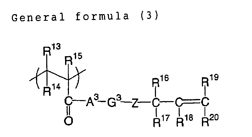
wherein A
1, A
2 and A
3 each independently represents
an oxygen atom, a sulfur atom or -N(R
21)-; R
21 represents an
alkyl group which may include one or more of
substituent(s); G
1, G
2 and G
3 each independently represents
a divalent organic group; X and Z each independently
represents an oxygen atom, a sulfur atom or -N(R
22)-; R
22
represents an alkyl group which may include one or more of
substituent(s); Y represents an oxygen atom, a sulfur atom,
a phenylene group which may include one or more of
substituent(s), or -N(R
23)-; R
23 represents an alkyl group
which may include one or more of substituent(s); and R
1 to
R
20 each independently represents a monovalent organic
group.
The radical generating agent which can be used in
the image recording layer is preferably an onium salt or a
triazine compound.
The present inventors have also found that the
aforementioned objectives can be attained by a heat-mode
negative image recording material in which a ratio of a
film hardness in a recording layer after and before an
exposure and/or a ratio of a surface contact angle of the
recording layer after and before an exposure, and have
thus made a third embodiment of the image recording
material of the invention.
More specifically, the third embodiment of the
invention provides an image recording material comprising
a substrate and a recording layer, which is provided on
the substrate and capable of image formation by heat mode
exposure, wherein the recording layer comprises:
Further, a fourth embodiment of the invention
provides an image recording material comprising a
substrate and a recording layer, which is provided on the
substrate and capable of image formation by heat mode
exposure, wherein the recording layer comprises:
The aforementioned polymerizable compound is
preferably a radical polymerizable compound having at
least four aromatic rings, or a polymer compound having a
polymerizable group in a side chain and insoluble in water
and soluble in an alkali aqueous solution.
In the image recording material of the third
embodiment of the invention, a mechanism of improvement in
the printing durability is not clarified, but, in a
recording layer hardened by a heat-mode exposure, in case
a ratio of a film hardness in an exposed area (such
hardness being hereinafter suitably represented as "X1")
to a film hardness before exposure (such hardness being
hereinafter suitably represented as "X2") is 1.1 or higher,
it is assumed that the hardened area in the recording
layer has a sufficiently high crosslinking density to form
a firmer film, thereby effectively inhibiting penetration
of a developing solution and reducing a damage to the
image portion, thus achieving an improvement in the
printing durability.
Also in the image recording material of the fourth
embodiment of the invention, a mechanism of improvement in
the printing durability is not clarified, but, in a
recording layer hardened by a heat-mode exposure, in case
a ratio of a surface contact angle in an exposed area
(such surface contact angle being hereinafter suitably
represented as "Y1") to a surface contact angle before
exposure (such surface contact angle being hereinafter
suitably represented as "Y2") is 1.1 or higher, such ratio
indicates an increased hydrophobicity of the surface of
the recording layer, thereby effectively inhibiting
penetration of a developing solution and reducing a damage
to the image portion, thus suppressing a deterioration of
the film property in the image portion and achieving an
improvement in the printing durability.
It is also conceived that a ratio Y1/Y2 of 1.1 or
higher (preferably 1.2 or higher) effectively inhibits
penetration of a fountain solution, used in a printing
operation, into the image portion, thereby suppressing a
destruction by coagulation of the image portion cause by a
penetration of the fountain solution or a peeling of the
recording layer from the interface of the substrate,
thereby achieving an improvement in the printing
durability.
Particularly in the image recording material of the
third or fourth embodiment of the invention, in case the
recording layer includes, as the polymerizable compound, a
radical polymerizable compound having at least four
aromatic rings, the ratio of film hardness (X1/X2) and/or
the ratio of surface contact angle (Y1/Y2) to provide a
significant effect of improving the printing durability.
Though a cause of such effect is not yet clarified,
it is estimated that the radical polymerizable compound
having at least four aromatic rings shows a large
quadrupole interaction resulting from the aromatic groups
to generate a strong monomer/monomer interaction, thereby
forming a firmer film particularly with a large film
hardness after exposure and an increased hydrophobicity
after hardening by exposure, thus suppressing the
penetration of the developing solution or the fountain
solution.
Also in case, as the polymerizable compound, there
is included a polymer compound having a polymerizable
group in a side chain and insoluble in water and soluble
in an alkali aqueous solution, the effect of improving the
printing durability is further enhanced. A cause for this
phenomenon is estimated that an interaction is also
generated between the polymer compound and a monomer in
addition to the aforementioned monomer/monomer interaction
and that such polymer compound itself has excellent film
properties.
It is also conceived that such polymerizable
compound having at least four aromatic rings can be
rearranged in the vicinity of the surface of the recording
layer, by a heating at the heat mode exposure. Such
phenomenon is estimated to contribute to an increase in
the Y1/Y2 ratio at the surface of the recording layer
after the exposure, thus leading to an improvement in the
printing durability.
In the present invention, "heat mode capable" means
that a recording by a heat mode exposure is possible.
In the following there will be explained a
definition of a heat mode exposure in the invention. As
described in Hans-Joachim Timpe, IS&Ts NIP 15: 1999
International Conference on Digital Printing Technologies,
p.209, it is known, for optically exciting a light
absorbing substance (for example a dye) in a
photosensitive material and forming an image through a
chemical or physical change, that two major modes are
present in a process from the photoexcitation of the light
absorbing substance to the chemical or physical change.
One is so-called photon mode in which the photoexcited
light absorbing substance is deactivated upon executing a
certain photochemical interaction (such as an energy
transfer or an electron transfer) with another reactive
substance in the photosensitive material and thus
activated reactive substance causes a chemical or physical
change necessary for the aforementioned image formation.
The other is so-called heat mode in which the photoexcited
light absorbing substance is deactivated upon generating a
heat, and such heat is utilized by a reactive substance to
cause a chemical or physical change necessary for the
aforementioned image formation. There are also other
special modes such as an ablation mode in which a
substance scatters in an explosive manner by a locally
concentrated optical energy, and a multi-photon absorption
mode in which a molecule absorbs plural photons at a same
time, but such special modes will not be explained further.
Exposure processes utilizing the aforementioned
modes are respectively called a photon mode exposure and a
heat mode exposure. A technical difference between the
photon mode exposure and the heat mode exposure lies in a
fact whether energies of exposing several photons can be
utilized in addition for an energy of a desired reaction.
For example, let us consider a case of inducing a reaction
with n photons. In the photon mode exposure, utilizing a
photochemical interaction, it is not possible to add up
energies of individual photons, because of a requirement
of the law of conservation of quantum energy and momentum.
Stated differently, in order to induce any reaction, there
is required a condition "energy of a photon ≥ energy of
reaction". On the other hand, in the heat mode exposure,
it is possible to add up energies since a photoexcitation
is followed by a heat generation whereby the optical
energy is converted into heat. Therefore, there is only
required a condition "energy of n photons ≥ energy of
reaction". However, such addition of energies is
restricted by a diffusion of heat. More specifically, in
case, in an object exposure area (reaction point), a next
photoexcitation-deactivation process occurs to generate
heat before heat is dissipated by thermal diffusion, the
heat is securely accumulated and added thereby elevating
the temperature of such point. However, in case a next
heat generation is late, the heat is dissipated and is not
accumulated. Thus, in the heat mode exposure, for a same
total exposure energy, a short irradiation of the light of
a higher energy amount and a long irradiation of the light
of a lower energy amount give different results, and the
short irradiation is advantageous for heat accumulation.
The photon mode exposure is basically free from such
phenomenon, although a similar phenomenon may naturally
arise by an influence of diffusion of succeeding reaction
species.
Thus, from the standpoint of characteristics of a
photosensitive material, a specific sensitivity (energy
amount for a reaction required for image formation) of a
photosensitive material in the photon mode becomes
constant with respect to an exposure power density
(W/cm2) (= energy density per unit time), but, in the heat
mode, the specific sensitivity of the photosensitive
material increases with an increase in the exposure power
density. Therefore, in a comparison of these modes with a
fixed exposure time capable of maintaining a practically
required productivity in an image recording material, the
photon mode exposure can usually achieve a high
sensitivity of about 0.1 mJ/cm2 but may results in a low-exposure
fog in an unexposed area because of the reaction
can be induced at any low exposure amount. On the other
hand, the heat mode exposure generally requires an
exposure of about 50 mJ/cm2 since the reaction can only be
induced beyond a certain exposure amount and also in
consideration of thermal stability of the photosensitive
material, but can avoid the drawback of low-exposure fog.
In practice, in the heat mode exposure, there is
required an exposure power density of 5,000 W/cm2 or
higher on the surface of the photosensitive material,
preferably 10,000 W/cm2 or higher. However, the use of a
laser of a high power density of 5.0 x 10⁵ W/cm2 or higher
causes an ablation phenomenon and is undesirable for
example for a smear of the light source, though such
phenomena has not been explained in detail.
BRIEF DESCRIPTION OF THE DRAWINGS
Fig. 1 is a chart showing a relationship between an
immersion time of a photosensitive composition in a model
solution and an electrostatic capacitance, to be used for
calculating an electrostatic capacitance rate of increase
ratio.
DETAILED DESCRIPTION OF THE INVENTION
In the following, the present invention will be
clarified in detail.
In an image recording material of the first
embodiment of the present invention, such as in a
planographic printing plate precursor, a photosensitive
composition included in an image recording layer coated on
a substrate is required, after a film formation and being
exposed by an infrared laser, to have an electrostatic
capacitance rate of increase ratio of 0.7 or less in an
exposed area to an unexposed area.
The electrostatic capacitance rate of increase ratio
used in the invention is calculated from an rate of
increase of an electrostatic capacitance to be explained
in the following. The electrostatic capacitance is
obtained by immersing a photosensitive composition coated
on a conductive substrate (aluminum) and a counter
electrode (such as aluminum, stainless steel or platinum)
in a model solution (in the invention, an alkali aqueous
solution to be explained in the following) and measuring
an impedance between the electrode with a sinusoidal AC
current of 1 kHz. In the actual measurement, the
conductive substrate has be prevented from direct contact
with the model solution, so that the immersion in the
model solution is executed after covering the
photosensitive composition, formed into a film, with a
shield material which the model solution does not permeate
except for an aperture of a predetermined area, provided
at a side of the surface coated with the photosensitive
composition and exposing the photosensitive composition as
a measurement sample in the solution. The electrostatic
capacitance increases with the permeation of the model
solution into the coated film of the photosensitive
composition which in contact with the model solution in
the above-mentioned aperture. In such process, an rate of
increase of the electrostatic capacitance becomes larger
as the permeation of the model solution is faster into the
coated film of the photosensitive composition. The
measurement on such coated film of the photosensitive
composition is executed for both of a sample prior to the
exposure to the infrared laser and a sample after a flush
exposure. In the invention, an electrostatic capacitance
rate of increase ratio is calculated from a following
equation:
Electrostatic capacitance rate of increase ratio =
(electrostatic capacitance rate of increase in an
exposed area/
electrostatic capacitance rate of increase in an
unexposed area).
In the following, a measured value used in the
invention indicates an electrostatic capacitance rate of
increase ratio of an exposed area and an unexposed area at
a time when the electrostatic capacitance rate of increase
in the unexposed area becomes maximum. At the measurement,
the model solution has to be maintained at a constant
temperature, and the invention uses values measured at
25°C.
Fig. 1 is a chart showing a plotting of the
electrostatic capacitance as a function of the immersion
time of the photosensitive composition in the model
solution, and, as shown in Fig. 1, an inclination of the
graph indicates the electrostatic capacitance rate of
increase. As an example, in case a change in the
electrostatic capacitance is obtained in the exposed area
and the unexposed area as shown in Fig. 1, the unexposed
area shows a maximum electrostatic capacitance rate of
increase at an immersion time of 25 seconds, with an
inclination of 35 nF/sec. As explained in the foregoing,
the electrostatic capacitance rate of increase ratio used
in the invention is determined from the electrostatic
capacitance rate of increase at a time when the
electrostatic capacitance rate of increase in the
unexposed area becomes maximum, so that the electrostatic
capacitance rate of increase in the exposed area at an
immersion time of 25 seconds is measured as 1.8 nF/sec.
Consequently, in such photosensitive composition, the
electrostatic capacitance rate of increase ratio is
determined as 0.05.
A smaller electrostatic capacitance rate of increase
ratio indicates a stronger inhibition for the penetration
of the model solution into the exposed area, corresponding
to a larger discrimination between the unexposed area and
the exposed area to the model solution (basically an
alkali aqueous solution of a predetermined pH value). The
present inventors have found that a smaller electrostatic
capacitance rate of increase ratio provides a better image
forming property also in an actual developing solution
constituted by an alkali aqueous solution. The
electrostatic capacitance rate of increase ratio providing
such satisfactory image is 0.7 or less, preferably 0.5 or
less and further preferably 0.3 or less.
As a reference, in an ordinary photosensitive
composition usable as a recording layer of a planographic
printing plate precursor for infrared laser exposure, the
electrostatic capacitance rate of increase ratio without a
post-heating is about 0.8 to 1.0, and an image with
excellent screen dot reproducibility can be obtained by
regulating such value to 0.7 or less by means to be
explained later.
Also, the specified model solution to be used in the
invention is selected according to a pKa value of an acid
group of the binder polymer to be used in the compostion.
For a pKa value less than 9, there is used a model
solution 1 (pH 11.8) to be explained later, and, for a pKa
value of 9 or higher, there is used a model solution 2 (pH
13) to be explained later.
Preparation of model solution 1 (pH 11.8)
There are used potassium hydroxide and potassium
carbonate as alkaline agents, polyethylene glycol
mononaphthyl ether as a solubilizing agent and water as a
solvent, and pH value is adjusted to 11.8 with tetrasodium
ethylenediamine tetraacetate as a buffer. An example of
specific formulation is shown in the following:
| Model solution 1 |
| potassium hydroxide | 0.7 g |
| potassium carbonate | 1.7 g |
| polyethylene glycol mononaphthyl ether | 53 g |
| tetrasodium ethylenediamine tetraacetate | 1.5 g |
| water | 955 g |
There are used potassium hydroxide and 1K potassium
silicate as alkaline agents, and water as a solvent, and
pH value is adjusted to 13 with tetrasodium
ethylenediamine tetraacetate as a buffer. An example of
specific formulation is shown in the following:
| Model solution 2 |
| potassium hydroxide | 10 g |
| 1K potassium silicate (CAS-1312-76-1) | 50 g |
| tetrasodium ethylenediamine tetraacetate | 0.03 g |
| water | 970 g |
By measuring the electrostatic capacitance rate of
increase in this manner, it is possible to estimate a
level of discrimination of the photosensitive composition
in a state of a coated film, to the model solution. For
example, in case the photosensitive composition of the
invention is utilized as a recording layer of a
planographic printing plate precursor, it is possible to
estimate the level of discrimination, by using an alkaline
developing solution, to be used in the development process,
as the model solution.
As explained in the foregoing, a lower electrostatic
capacitance rate of increase ratio is preferred, and the
electrostatic capacitance rate of increase can be lowered
by regulating a compound relating to a film hardening in
the photosensitive composition, and, for example in case
of a photosensitive composition hardenable by
polymerization, by adjusting a type and an addition amount
of a radial generating agent or a radical polymerizable
compound.
More specifically, there can be used, for example, a
method of increasing an amount of the radical generating
agent, using a radical generating agent of a higher
sensitivity, increasing an amount of the radical
polymerizable compound, or using a radical polymerizable
compound of polyfunctional character.
In case the photosensitive composition is used as an
image recording layer of a planographic printing plate
precursor and is hardened by a crosslinking reaction or a
polymerization reaction induced by an exposure, the
photosensitive composition in an exposed area, namely in
an image portion, may be hardened uniformly over the
entire coated film or hardened in an upper layer portion
of the coated film, namely only the vicinity of a surface
of the exposed recording layer, while the hardening
reaction does not proceed sufficiently in a deeper part of
the recording layer, but it is particularly preferred that
only an upper layer portion of the image is hardened. In
case the upper layer portion alone of the image is
hardened, the lower layer portion of the image is not
hardened by crosslinking and is dissolved in a developing
solution, thereby providing a sharp-cut image. Such state
is preferred as it provides a sharp image of a high
resolution in a print.
Such film hardened state can be attained also by
regulating a type and an addition amount of an infrared
absorbing agent, in addition to those of the radical
generating agent and the radical polymerizable compound
explained in the foregoing. This is because an increase
in the amount of the infrared absorbing agent improves a
photothermal conversion efficiency at the exposed surface
thereby stimulating an efficient hardening, but reduces
the optical transmission of the entire film thereby
suppressing the hardening in a deeper part of the film.
In an image recording material of the second
embodiment of the invention, a gradation (γ) of an image
obtained by coating an image recording layer on a
substrate, followed by an exposure with an infrared laser
light and a development process, satisfies a condition γ ≥
4, preferably γ ≥ 6.
In the invention, a gradation (γ) of an image means
an inclination of a characteristic curve indicating a
correlation between an image density on the printing plate
and an exposure amount.
The characteristic curve, to be used for determining
the γ value in the image recording material of the second
embodiment of the invention (preferably a negative working
planographic printing plate precursor for infrared
exposure), can be prepared by forming an image recording
layer on a substrate, executing exposures under different
exposure amounts varied by an output of a plate setter,
measuring densities of images obtained by development
processes, and plotting dependancies of image densities on
the exposure amounts. A maximum density of the image
densities is used as normalized value 1. In case the
photosensitive composition is used as the image recording
layer of the planographic printing plate precursor, a
coloring agent is usually added for the purpose of plate
inspection, so that the image density can be directly
measured.
In the invention, the γ value defined as an image
gradation indicates an inclination of the characteristic
curve within a density range from 0.4 to 0.8 [(0.8 -
0.4)/(difference in exposure amounts (logarithmic)
providing densities 0.4 and 0.8)]. The density was
measured with a Macbeth reflective densitometer RD-918
(trade name, manufactured by Macbeth), and at a cyan
density utilizing a red filter equipped on the
densitometer. s
In general, the gradation (γ) of the image is varied
depending on, for example, an exposure amount, an exposure
time, a developing method, a type of a developing solution
and the like. However, as is understood from the fact that
photo-curable compositions used in the image recording
layer of the planographic printing plate precursor usually
have a γ value of about 0.5 to 3.5, there has not been
attained a gradation (γ) of 4 or higher in the image
obtained by an infrared laser exposure and a development
process.
An effective method for controlling the gradation
(γ) of the image can be a method of varying the reactivity
of a polymerization initiator contained in a
photopolymerizable compound. For example, in case the
polymerization initiator is a compound capable of
generating a radical by the light, the reactivity becomes
higher as a LUMO level (lowest unoccupied molecular
orbital) of the polymerization initiator becomes lower
under a LUMO level of a dye for generating an electron by
a light absorption, namely as the polymerization initiator
has a higher electron accepting property. Also in case
the polymerization initiator is a compound capable of
generating a radical by heat, the reactivity becomes
higher as a thermal decomposition temperature of the
polymerization initiator becomes lower.
Based on such standpoints, compounds of following
structures can be advantageously used in the
photosensitive composition constituting the image
recording layer of the invention, but such examples are
not restrictive.
In order to realize such image gradation, the
photosensitive composition constituting the image
recording layer preferably includes a polymer compound
which includes at least one of structural units
represented by following structural formulas (1), (2) and
(3) in an amount of 0.1 mol% or more and less than 30 mol%
and which can be one of dissolved and swollen by one of
water and an alkaline aqueous solution.
wherein A
1, A
2 and A
3 each independently represents
an oxygen atom, a sulfur atom or -N(R
21)-; R
21 represents an
alkyl group which may have substituent(s); G
1, G
2 and G
3
each independently represents a divalent organic group; X
and Z each independently represents an oxygen atom, a
sulfur atom or -N(R
22)-; R
22 represents an alkyl group which
may have substituent(s); Y represents an oxygen atom, a
sulfur atom, a phenylene group which may have
substituent(s), or -N(R
23) -; R
23 represents an alkyl group
which may have substituent(s); and R
1 to R
20 each
independently represents a monovalent organic group.
Such high gradation of the image means that the
image forming property of the photosensitive composition
does not significantly depend on an exposure energy, and
it is considered that the film crosslinked and hardened by
the light, namely the image portion of the invention,
shows excellent printing properties such as a dot
sharpness and provides a sufficient printing durability
even to a screen dot of a small area.
For obtaining an image gradation suitable for the
invention, there can be adopted a method of using a
polymerization initiator of a high reactivity in the image
recording layer, or a method of adding a polymer of a high
reactivity in the composition, and, in particular, the use
of a reactive polymer stimulates a rapid proceeding of the
hardening reaction after the exposure, thereby providing
an image of a high gradation. Such reactive polymer can
be arbitrarily selected among polymers having specified
reactive functions groups, but particularly advantageous
is a polymer compound which includes at least one of
structural units represented by the foregoing structural
formulas (1), (2) and (3) in an amount of 0.1 mol% or more
and less than 30 mol% and which can be one of dissolved
and swollen by one of water and an alkaline aqueous
solution.
A mechanism of obtaining a high gradation, by the
addition of a polymer compound having a high reactivity
and serving as a binder into the composition, has not been
clarified yet, however it is estimated as follows. The
structural unit represented by the general formula (1),
(2) or (3), having a functional group of a high radical
reactivity, causes a crosslinking reaction among the
binder polymers promptly after the radical generation by
the scanned exposure with the infrared laser. It is thus
estimated that the presence of such structural unit in the
polymer composition very rapidly induces a formation of a
hardened film, namely an insolubilization in the
developing solution or in an organic solvent, thereby
providing a hardened film of a sufficient hardness to form
a strong image portion even in a screen dot or a fine line,
thus attaining a high gradation.
The polymer compound advantageously employable in
the invention is a polymer compound which includes at
least one of structural units represented by the foregoing
structural formulas (1), (2) and (3) in an amount of 0.1
mol% or more and less than 30 mol% and which can be one of
dissolved and swollen by one of water and an alkaline
aqueous solution.
In the foregoing general formula (1), R1 to R3 each
independently represents a monovalent organic group, which
can be a hydrogen atom, or an alkyl group that may have
substituent(s), and, a hydrogen atom is preferred for R1
and R2, and a hydrogen atom or a methyl group is preferred
for R3.
R4 to R6 each independently represents a monovalent
organic group, which, for R4, can be a hydrogen atom or an
alkyl group that may have substituent(s), preferably a
hydrogen atom, a methyl group, or an ethyl group. R5 and
R6 each independently represents a hydrogen atom, a
halogen atom, an alkoxycarbonyl group, a sulfo group, a
nitro group, a cyano group, an alkyl group which may have
substituent(s), an aryl group which may have
substituent(s), an alkoxy group which may have
substituent(s), an aryloxy group which may have
substituent(s), an alkylsulfonyl group which may have
substituent(s), or an arylsulfonyl which may have
substituent(s), among which preferred is a hydrogen atom,
an alkoxycarbonyl group, an alkyl group which may have
substituent(s) or an aryl group which may have
substituent(s).
Examples of the substituent that can be introduced
include a methoxycarbonyl group, an ethoxycarbonyl group,
an isopropyloxycarbonyl group, a methyl group, an ethyl
group and a phenyl group.
A1 and X each independently represents an oxygen atom,
a sulfur atom or -N(R21)-, wherein R21 can be a hydrogen
atom or an alkyl group which may have substituent(s).
G1 represents a divalent organic group, preferably an
alkyl group which may have substituent(s). More
preferably it can be an alkyl group having from 1 to 20
carbon atoms which may have substituent(s), a cycloalkyl
group having from 3 to 20 carbon atoms which may include a
substituent, or an aromatic group having from 6 to 20
carbon atoms which may have substituent(s), and, in
consideration of a strength and a developing property,
further preferred is a linear or ramified alkyl group
having from 1 to 10 carbon atoms which may have
substituent(s), a cycloalkyl group having from 3 to 10
carbon atoms which may include a substituent, or an
aromatic group having from 6 to 12 carbon atoms which may
have substituent(s).
A substituent in G1 preferably does not include a
group in which a hydrogen atom is bonded to a hetero atom,
such as a hydroxyl group, an amino group, a thiol group or
a carboxyl group. A compound including such group,
containing a hydrogen atom bonded to a hetero atom, in a
connecting group portion may deteriorate a storage
stability when used in combination with an onium salt as
an initiator to be explained later.
In the foregoing general formula (2), R7 to R9 each
independently represents a monovalent organic group, which
can be a hydrogen atom, or an alkyl group that may have
substituent(s), and, a hydrogen atom is preferred for R7
and R8, and a hydrogen atom or a methyl group is preferred
for R9.
R10 to R12 each independently represents a monovalent
organic group, which can be a hydrogen atom, a halogen
atom, a dialkylamino group, an alkoxycarbonyl group, a
sulfo group, a nitro group, a cyano group, an alkyl group
which may have substituent(s), an aryl group which may
have substituent(s), an alkoxy group which may have
substituent(s), an aryloxy group which may have
substituent(s), an alkylsulfonyl group which may have
substituent(s), or an arylsulfonyl which may have
substituent(s), among which preferred is a hydrogen atom,
an alkoxycarbonyl group, an alkyl group which may have
substituent(s) or an aryl group which may have
substituent(s).
Examples of the substituent that can be introduced
are similar to those cited in the general formula (1).
A2 represents an oxygen atom, a sulfur atom or
-N(R21)-, wherein R21 can be a hydrogen atom or an alkyl
group which may have substituent(s).
G2 represents a divalent organic group, preferably an
alkyl group which may have substituent(s). More
preferably it can be an alkyl group having from 1 to 20
carbon atoms, a cycloalkyl group having from 3 to 20
carbon atoms which may include a substituent, or an
aromatic group having from 6 to 20 carbon atoms which may
have substituent(s), and, in consideration of a strength
and a developing property, further preferred is a linear
or ramified alkyl group having from 1 to 10 carbon atoms
which may have substituent(s), a cycloalkyl group having
from 3 to 10 carbon atoms which may include a substituent,
or an aromatic group having from 6 to 12 carbon atoms
which may have substituent(s).
A substituent in G2 preferably does not include a
group in which a hydrogen atom is bonded to a hetero atom,
such as a hydroxyl group, an amino group, a thiol group or
a carboxyl group. A compound including such group,
containing a hydrogen atom bonded to a hetero atom, in a
connecting group portion may deteriorate a storage
stability when used in combination with an onium salt as
an initiator to be explained later.
Y represents an oxygen atom, a sulfur atom, -N(R23)-or
a phenylene group which may have substituent(s),
wherein R23 can be a hydrogen atom or an alkyl group which
may have substituent(s).
In the foregoing general formula (3), R13 to R15 each
independently represents a monovalent organic group, which
can be a hydrogen atom, or an alkyl group that may have
substituent(s), and, a hydrogen atom is preferred for R13
and R14, and a hydrogen atom or a methyl group is preferred
for R15.
R16 to R20 each independently represents a monovalent
organic group, which can be a hydrogen atom, a halogen
atom, a dialkylamino group, an alkoxycarbonyl group, a
sulfo group, a nitro group, a cyano group, an alkyl group
which may have substituent(s), an aryl group which may
have substituent(s), an alkoxy group which may have
substituent(s), an aryloxy group which may have
substituent(s), an alkylsulfonyl group which may have
substituent(s), or an arylsulfonyl which may have
substituent(s), among which preferred is a hydrogen atom,
an alkoxycarbonyl group, an alkyl group which may have
substituent(s) or an aryl group which may have
substituent(s). Examples of the substituent that can be
introduced are similar to those cited in the general
formula (1). A3 and Z each independently represents an
oxygen atom, a sulfur atom or -N(R21)-, wherein R21 is
similar to that in the general formula (1).
G3 represents a divalent organic group, preferably an
alkyl group which may have substituent(s). More
preferably it can be an alkyl group having from 1 to 20
carbon atoms, a cycloalkyl group having from 3 to 20
carbon atoms which may include a substituent, or an
aromatic group having from 6 to 20 carbon atoms which may
have substituent(s), and, in consideration of a strength
and a developing property, further preferred is a linear
or ramified alkyl group having from 1 to 10 carbon atoms
which may have substituent(s), a cycloalkyl group having
from 3 to 10 carbon atoms which may include a substituent,
or an aromatic group having from 6 to 12 carbon atoms
which may have substituent(s).
A substituent in G3 preferably does not include a
group in which a hydrogen atom is bonded to a hetero atom,
such as a hydroxyl group, an amino group, a thiol group or
a carboxyl group. A compound including such group,
containing a hydrogen atom bonded to a hetero atom, in a
connecting group portion may deteriorate a storage
stability of the photosensitive composition of the present
invention when used in combination with an onium salt as
an initiator to be explained later.
Such polymer compound can be synthesized according
to a method described for example in JP-A No. 2002-62648,
for example a method copolymerizing at least a radical
polymerizable compound represented by a following general
formula (4) in an amount of 0.1 mol% or higher and less
than 30 mol%, and at least one of other radical
polymerizable compounds not including a structural unit
represented by the following general formula (4) in an
ordinary radical polymerization to obtain a precursor of a
desired polymer compound, and then extracting a proton
with a base to cleave a group L, thereby obtained a
desired polymer compound having a structure represented by
the foregoing general formula (1).
Specific examples of the reactive polymer compound
advantageously employable in the invention are shown below
together with a weight-averaged molecular weights thereof,
however, the invention is not limited to such examples.
In consideration of the effect of the invention,
Such polymer compound having a high reactivity is
preferably contained in an mount from 20 to 80 wt.%, more
preferably from 40 to 70 wt.%, in a solid content of the
photosensitive composition constituting the image
recording material of the invention. An effect for
improving the gradation cannot be obtained sufficiently
when the content of polymer compounds are excessively low.
An image recording material of the third embodiment
of the invention is provided, on a substrate, with a
recording layer capable of image formation by a heat mode
exposure and including a polymerizable compound, a
photothermal converting agent and a radical generating
agent (a compound generating a radical by an exposure to a
light of a wavelength absorbable by the photothermal
converting agent), wherein a ratio (X1/X2) of a film
hardness after exposure (X1) and a film hardness before
exposure (X2) is 1.1 or higher.
Also, an image recording material of the fourth
embodiment of the invention is provided, on a substrate,
with a recording layer capable of image formation by a
heat mode exposure and including a polymerizable compound,
a photothermal converting agent and a radical generating
agent (a compound generating a radical by an exposure to a
light of a wavelength absorbable by the photothermal
converting agent), wherein a ratio (Y1/Y2) of a surface
contact angle after exposure (Y1) and a surface contact
angle before exposure (Y2) is 1.1 or higher.
The film hardness and the surface contact angle in
the image recording material of the invention, measuring
methods therefor, and compounds employable in the image
recording material are explained below.
Film hardness
In an image recording material of the third
embodiment of the invention, a ratio (X1/X2) of a film
hardness after exposure (X1) and a film hardness before
exposure (X2) in the recording layer is required to be 1.1
or higher, preferably 1.2 or higher for further improving
the printing durability.
In a negative working image recording material,
there may be applied a post-heating process (burning
process) in order to further increase the strength of a
formed image portion, but the film hardness after the
exposure, in the invention, means a film hardness in a
state after the exposure but not subjected to the post-heating
process.
In the invention, the film hardness can be measured
by methods known in the art. Specifically, it can be
determined, for example, from a displacement curve that is
prepared by applying pressures to an image recording layer
by a pressing member having a triangular pyramidal end
equipped with an ultra micro press-in hardness measuring
apparatus, that is constituted by combining a microscope
equipped with a piezo actuator and a transducer, and then
by measuring displacements and loads for obtaining the
displacement curve.
The film hardness (hereinafter represented as "H")
is given by H = Lmax/A, wherein Lmax is a maximum load and A
indicates a contact cross section of the pressure member
when such maximum load is recorded. The contact cross
section A can be determined by calculation, based on an
aspect ratio of the pressure member, from an inclination
hplastic of a tangential line linearly approximating initial
30 % of a gradual loading curve. Based on such film
hardness measuring method, a press-in depth (htotal) of the
pressure member is regulated to obtain the film hardness
of an upper part of the recording layer and of the entire
recording layer. More specifically, there can utilized a
method described in X. Yun, R. Hsiao, D. B. Bogy, C. S.
Bhatia, "Computer Mechanics Laboratory, Technical Report",
No. 96-015, 1(1996). In the invention, there was used a
press-in apparatus (trade name: Triboscope, manufactured
by Hysitron Inc.), which was mounted on an atomic force
microscope (AFM) (trade name: SPA300, manufactured by
Seiko Instruments Inc.).
A method for regulating the film hardness ratio of
the recording layer at 1.1 or higher is not particularly
restricted, but, in view of increasing the film hardness
after the exposure, a control is possible for example by
selecting, as the polymerizable compound, a compound
having a satisfactory reactivity and capable of showing a
strong interaction after the hardening.
Surface contact angle
In an image recording material of the fourth
embodiment of the invention, a ratio (Y1/Y2) of a surface
contact angle after exposure (Y1) and a surface contact
angle before exposure (Y2) in the recording layer is
required to be 1.1 or higher, preferably 1.2 or higher for
further improving the printing durability.
In the invention, the surface contact angle is
obtained by dropping water onto a recording layer and
measuring a contact angle of the water with a contact
angle meter (trade name: CA-Z, manufactured by Kyowa
Kaimen Kagaku Co.).
In a negative working image recording material,
there may be applied a post-heating process (burning
process) in order to further increase the strength of a
formed image portion, but the surface contact angle after
the exposure, in the invention, means a surface contact
angle in a state after the exposure but not subjected to
the post-heating process.
A method for controlling the surface contact angle
ratio of the recording layer at 1.1 or higher is not
particularly restricted. However, in view of increasing
the surface contact angle after the exposure, there may be
preferably used a method of adding a hydrophobic compound
which can move to and can be localized in the vicinity of
the surface of the recording layer by an exposure or by
heating, or a method of adding, as a polymerizable
compound, a compound having a satisfactory reactivity and
capable of inducing a partial hardening thereby
suppressing a diffusing movement of a hydrophilic
component in the recording layer (for example a compound
having an acryl group or a methacryl group).
The image recording layer of the image recording
material of the invention includes an infrared absorbing
agent (photothermal converting agent), a radical
generating agent, a polymerizable compound, and,
preferably for improving the film property, a general
binder polymer other than the aforementioned polymerizable
compound. These components will be explained below.
Infrared Absorbing Agent (Photothermal converting agent)
A photothermal converting agent is used in the image
recording material of the invention in order to execute a
recording by a heat mode exposure by, representatively, a
laser that emits an infrared ray. The photothermal
converting agent has a function to absorb light of a
specified wavelength and to convert it to heat. By thus
generated heat, namely by a heat mode exposure with the
light of a wavelength absorbable by the photothermal
converting agent, the radical generating agent is
decomposed to generate a radical. The photothermal
converting agent to be used in the invention can be any
substance capable of converting absorbed light into heat.
Generally, a dye or a pigment having an absorption maximum
at a wavelength of an infrared laser to be used for
information writing, namely in a wavelength region of 760
to 1200 nm, which are known as an infrared absorbing agent,
can be used.
As the dye, commercially available dyes and known
those described for example in "Senryo Binran (Dye
Handbook)" (edited by Organic Synthetic Chemical Society,
1970) can be used. Specific examples of such dye include
azo dyes, metal complex azo dyes, pyrazolone azo dyes,
naphthoquinone dyes, anthraquinone dyes, phthalocyanine
dyes, carbonium dyes, quinonimine dyes, methine dyes,
cyanine dyes, squalirium dyes, pyrilium dyes, and metal
thiolate dyes.
Preferred dyes include, for example, cyanine dyes
described in JP-A Nos. 58-125246, 59-84356, 59-202829 and
60-78787, methine dyes described in JP-A Nos. 58-173696,
58-181690 and 58-194595, naphthoquinone dyes described in
JP-A Nos. 58-112793, 58-224793, 59-48187, 59-73996, 60-52940
and 60-63744, squalirium dyes described in JP-A No.
58-112792 and cyanine dyes described in BP No. 434,875.
There can also be advantageously used a near
infrared absorption sensitizer described in USP No.
5,156,938, and there can be preferably used substituted
arylbenzo(thio)pyrilium salts described in USP No.
3,881,924, trimethinethiapyrilium salts described in JP-A
No. 57-142645 (USP No. 4,327,169), pyrilium compounds
described in JP-A Nos. 58-181051, 58-220143, 59-41363, 59-84248,
59-84249, 59-146063 and 59-146061, cyanine dyes
described in JP-A No. 59-216146, pentamethinethiopyrilium
salts described in USP No. 4,283,475 and pyrilium
compounds described in JP-B No. 5-13514 and 5-19702.
Also other preferred examples of the dye are near
infrared absorbing dyes described in U.S.P. No. 4,756,993
by formulas (I) and (II).
Among these dyes, particularly preferred are cyanine
dyes, squalirium dyes, pyrilium salts, and nickel thiolate
complexes. Further, more preferred are cyanine dyes, and
most preferred is a cyanine dye represented by a following
general formula (a):
In the general formula (a), X
1 represents a hydrogen
atom, a halogen atom, -NPh
2, X
2-L
1 or a following group; X
2
represents an oxygen atom, a nitrogen atom or a sulfur
atom; L
1 represents a hydrocarbon group having from 1 to 12
carbon atoms, an aromatic ring having a hetero atom, or a
hydrocarbon group having from 1 to 12 carbon atoms
including a hetero group; a hetero atom indicates N, S, O,
a halogen atom or Se; Xa has a definition same as Za to
be explained later; and Ra represents a substituent group
selected from a hydrogen atom, an alkyl group, an aryl
group, a substituted or non-substituted amino group and a
halogen atom:
R1 and R2 each independently represents a hydrocarbon
group having 1 to 12 carbon atoms. In consideration of
stability in storage of the recording layer coating liquid,
each of R1 and R2 is preferably a hydrocarbon group having
from 2 or more carbon atoms, and more preferably R1 and R2
are mutually bonded to form a five-membered ring or a six-membered
ring.
Ar1 and Ar2, which may be same or different, each
represents an aromatic hydrocarbon group which may have
substituent(s). Preferred examples of the aromatic
hydrocarbon group include a benzene ring and a naphthalene
ring. Also preferred examples of the substituent include
a hydrocarbon group having 12 or less carbon atoms, a
halogen atom, and an alkoxy group having 12 or less carbon
atoms. Y1 and Y2, which may be same or different, each
represents a sulfur atom or a dialkylmethylene group
having 12 or less carbon atoms. R3 and R4, which may be
same or different, each represents a hydrocarbon group
having 20 or less carbon atoms, which may have
substituent(s). Preferred examples of the substituent
include an alkoxy group having 12 or less carbon atoms, a
carboxyl group and a sulfo group. R5, R6, R7 and R8, which
may be same or different, each represents a hydrogen atom,
or a hydrocarbon group having 12 or less carbon atoms.
Hydrogen atom is preferred because of the availability of
the raw material. Za represents a counter anion. However,
Za is not required in case a cyanine dye represented by
the general formula (a) has an anionic substituent in the
structure does not require a charge neutralization. In
consideration of the stability in storage of the recording
layer coating liquid, Za is preferably a halogen ion, a
perchlorate ion, a tetrafluoroborate ion, a
hexafluorophosphate ion, or a sulfonate ion, and more
preferably a perchlorate ion, a hexafluorophosphate ion or
an arylsulfonate ion.
Specific examples of the cyanine dyes represented by
the general formula (a) and advantageously employable in
the invention are described in JP-A No. 2001-133969,
paragraphs [0017] to [0019].
Other particularly preferred examples include
specified indolenincyanine dyes described in the
aforementioned Japanese Patent Applications Nos. 2001-6326
and 2001-237840.
Examples of the pigment employable in the invention
include commercially available pigments and pigments
described in Color Index (C. I.), "Saishin Ganryo Binran
(Latest Pigment Handbook)" (Pigment Technology Society of
Japan, 1977), "Saishin Ganryo Ouyou Gijutsu (Latest
Pigment Application Technology)" (CMC Press, 1986), and
"Insatsu Ink Gijutsu (Printing Ink Technology)" (CMC Press,
1984).
The type of the pigment can be a black pigment, an
yellow pigment, an orange pigment, a brown pigment, a red
pigment, a purple pigment, a blue pigment, a green pigment,
a fluorescent pigment, a metal powder pigment, or a
polymer bonded pigment. Specific examples include
insoluble azo pigments, azo rake pigments, condensed azo
pigments, chelate azo pigments, phthalocyanine pigments,
anthraquinone pigments, perylene and perynone pigments,
thioindigo pigments, quinachrydone pigments, dioxazine
pigments, isoindolinone pigments, quinophthalone pigments,
vat rake pigments, azine pigments, nitroso pigments, nitro
pigments, natural pigments, fluorescent pigments,
inorganic pigments and carbon black, among which preferred
is carbon black.
These pigments may be used with or without a surface
treatment. The surface treating method can be, for
example, a method of surface coating with resin or wax, a
method of depositing a surfactant, or a method of bonding
a reactive substance (for example a silane coupling agent,
an epoxy compound or polyisocyanate) to the pigment
surface. These surface treating methods are described in
"Kinzoku Sekken no Seishitsu to Ouyou (Properties and
Applications of Metal Soaps)" (Saiwai Shobo), "Insatsu Ink
Gijutsu (Printing Ink Technology)" (CMC Press, 1984) and
"Saishin Ganryo Ouyou Gijutsu (Latest Pigment Application
Technology)" (CMC Press, 1986).
The particle size of the pigment is preferably
within a range of 0.01 to 10 µm, more preferably 0.05 to 1
µm and most preferably 0.1 to 1 µm. A particle size of
the pigment less than 0.01 µm is undesirable in the
stability of dispersion in the image recording layer
coating liquid, and a particle size exceeding 10 µm is
undesirable in the uniformity of the image recording layer.
In order to disperse the pigment, there can be used
a known technology used in ink manufacture or toner
manufacture. A dispersing machine can be an ultrasonic
dispersing device, a sand mill, an attriter, a pearl mill,
a super mill, a ball mill, an impeller, a disperser, a KD
mill, a colloid mill, a dynatron, a three-roll mill or a
pressurized kneader. Details are described in "Saishin
Ganryo Ouyou Gijutsu (Latest Pigment Application
Technology)" (CMC Press, 1986).
In case of applying the photosensitive composition
of the present invention to a recording layer of a
negative working planographic printing plate precursor,
the photosensitive layer preferably has an optical density
within a range of from 0.1 to 3.0 at the absorption
maximum within the wavelength range of from 760 to 1200 nm.
A value outside such range tends to result in a lowered
sensitivity. As the optical density is determined by an
amount of addition of the infrared absorbing agent and a
thickness of the image recording layer, a desired optical
density can be obtained by controlling both parameters.
The optical density of the image recording layer can be
measured by an ordinary method. The measurement can be
achieved, for example, by forming, on a transparent or
white substrate, an image recording layer of a thickness
suitably determined within a range of a dry coating amount
required for the planographic printing plate, and
executing a measurement with a transmission optical
densitometer, or forming an image recording layer on a
reflective substrate such as of aluminum and measuring a
reflective density.
Radical Ggenerating Agent
In the presentinvention, it is necessary to add a
radical generating agent, which generates a radical by an
exposure of a wavelength absorbable by the infrared
absorbing agent (photothermal converting agent).
The radical generating agent to be used in the
invention is a compound capable of generating radicals by
an exposure at a wavelength absorbable by the photo
thermal converting agent, initiating a polymerization
reaction of the radical polymerizable compound, and
accelerating the polymerization reaction, depending on a
reaction mechanism of such compound.
The radical generating agent can preferably be, for
example, (a) an aromatic ketone, (b) an onium salt, (c) an
organic peroxide, (d) a thio compound, (e) a
hexaarylbiimidazole compound, (f) a ketoxime ester, (g) a
borate compound, (h) an azinium compound, (i) a metalocene
compound, (j) an active ester compound, or (k) a compound
having a carbon-halogen bond. Specific examples of (a) to
(k) are shown in the following, but the present invention
is not limited by such examples.
(a) Aromatic ketones
For the aforementioned (a) aromatic ketones, there
can be used compounds having a benzophenone skeleton or a
thioxanthone skeleton, described in "Radiation Curing in
Polymer Science and Technology", J. P. Fouassieur, J. F.
Rabek (1993), pp.77-117. For example, there can be used
following compounds:
Particularly preferable examples of the (a) aromatic
ketone include an α-thiobenzophenone compound described in
JP-B No. 47-6416 and a benzoin ether compound described in
JP-B No. 47-3981, such as a following compound:
There can also be used an α-substituted benzoin
compound described in JP-B No. 47-22326, such as a
following compound:
There can also be used a benzoin derivative
described in JP-B No. 47-23664, an alloyl phosphonic acid
ester described in JP-A No. 57-30704, or a
dialkoxybenzophenone described in JP-B No. 60-26483, for
example a following compound:
There can also be used a benzoin ether described in
JP-B No. 60-26403 and JP-A No. 62-81345, for example a
following compound:
There can also be used an α-aminobenzophenone
described in JP-B No. 1-34242, USP No. 4,318,791 and EP No.
0284561A1, for example following compounds:
There can also, be used p-di(dimethylaminobenzoyl)benzene
described in JP-A No. 2-211452,
for example a following compound:
There can also be used a thio-substituted aromatic
ketone described in JP-A No. 61-194062, for example a
following compound:
There can also be used an acylphosphine sulfide
described in JP-B No. 2-9597, for example following
compounds:
There can also be used an acyl phosphine described
in JP-B No. 2-9596, for example a following compound:
There can also be used a thioxanthone described in
JP-B No. 63-61950 and a coumarin described in JP-B No. 59-42864.
(b) Onium salt compound
The aforementioned (b) onium salt compound can be
compounds represented by followinggeneral formula (II) to
(IV):
In the formula (II), Ar1 and Ar2 each independently
represents an aryl group having 20 or less carbon atoms
which may have a substitutent. In case the aryl group has
a substituent, preferred examples of the substituent
include a halogen atom, a nitro group, an alkyl group
having 12 or less carbon atoms, an alkoxy group having 12
or less carbon atoms, and an aryloxy group having 12 or
less carbon atoms. (Z2) represents a counter ion selected
from a group of a halogen ion, a perchlorate ion, a
carboxylate ion, a tetrafluoroborate ion, a
hexafluorophosphate ion, and a sulfonate ion, and is
preferably a perchlorate ion, a hexafluorophosphate ion,
or an arylsulfonate ion.
In the formula (III), Ar3 represents an aryl group
having 20 or less carbon atoms, which may have
substituent(s). Preferred examples of the substituent
include a halogen atom, a nitro group, an alkyl group
having 12 or less carbon atoms, an alkoxy group having 12
or less carbon atoms, an aryloxy group having 12 or less
carbon atoms, an alkylamino group having 12 or less carbon
atoms, a dialkylamino group having 12 or less carbon atoms,
an arylamino group having 12 or less carbon atoms, and a
diarylamino group having 12 or less carbon atoms. (Z3)
represents a counter ion of a same definition as (Z2) in
the general formula (II).
In the formula (IV), R23, R24 and R25, which may be
same or different, each independently represents a
hydrocarbon group having 20 or less carbon atoms, which
may have substituent(s). Preferred examples of the
substituent include a halogen atom, a nitro group, an
alkyl group having 12 or less carbon atoms, an alkoxy
group having 12 or less carbon atoms, and an aryloxy group
having 12 or less carbon atoms. (Z4) represents a counter
ion of a same definition as (Z2) in the general formula
(II).
Specific examples of the onium salt advantageously
employable in the invention are described in Japanese
Patent Application 11-310623, paragraphs [0030] to [0033],
and Japanese Patent Application No. 2000-160323,
paragraphs [0015] to [0046].
The onium salt to be used in the invention
preferably has a maximum absorption wavelength not
exceeding 400 nm, more preferably not exceeding 360 nm.
The absorption wavelength in such ultraviolet region
allows to handle the planographic printing plate precursor
under a white light. In the image forming material of the
first and second embodiments of the invention, it is
particularly preferred to employ an onium salt as the
radical generating agent.
(c) Organic peroxide
The aforementioned (c) organic peroxide includes
most of organic compounds containing at least an oxygen-oxygen
bond in the molecule, of which examples include
methyl ethyl ketone peroxide, cyclohexanone peroxide,
3,3,5-trimethylcyclohexanone peroxide, methylcyclohexanone
peroxide, acetylacetone peroxide, 1,1-bis(tert-butylperoxy)-3,3,5-trimethylcyclohexanone,
1,1-bis(tert-butylperoxy)-cyclohexane,
2,2-bis(tert-butylperoxy)-butane,
tert-butyl hydroperoxide, cumene hydroperoxide,
diisopropylbenzene hydroperoxide, paramethane
hydroperoxide, 2,5-dimethylhexane-2,5-dihydroperoxide,
1,1,3,3-tetramethylbutyl hydroperoxide, di-tert-butyl
peroxide, tert-butylcumyl peroxide, dicumyl peroxide,
bis(tert-butylperoxyisopropyl)benzene, 2,5-dimethyl-2,5-di(tert-butylperoxy)hexane,
2,5-xanoyl peroxide, succinoyl
peroxide, benzoyl peroxide, 2,4-dichlorobenzoyl peroxide,
meta-toluoyl peroxide, diisopropyl peroxydicarbonate, di-2-ethylhexyl
peroxydicarbonate, di-2-ethoxyethyl
peroxydicarbonate, dimethoxyisopropyl peroxycarbonate,
di(3-methyl-3-methoxybutyl) peroxydicarbonate, tert-butyl
peroxyacetate, tert-butyl peroxypivalate, tert-butyl
peroxy neodecanoate, tert-butyl peroxyoctanoate, tert-butylperoxy-3,5,5-trimethylhexanoate,
tert-butyl
peroxylaurate, tert-carbonate, 3,3',4,4'-tetra-(t-butylperoxycarbonyl)benzophenone,
3,3',4,4'-tetra-(t-amylperoxycarbonyl)benzophenone,
3,3',4,4'-tetra-(t-hexylperoxycarbonyl)benzophenone,
3,3',4,4'-tetra-(t-octylperoxycarbonyl)benzophenone,
3,3',4,4'-tetra-(cumylperoxycarbonyl)benzophenone,
3,3',4,4'-tetra-(p-isopropylcumylperoxycarbonyl)benzophenone,
carbonyldi(t-butylperoxy
dihydrogen diphthalate) and carbonyldi(t-hexylperoxy
dihydrogen diphthalate).
Among these, preferred is a peroxyester such as
3,3',4,4'-tetra-(t-butylperoxycarbonyl)benzophenone,
3,3',4,4'-tetra-(t-amylperoxycarbonyl)benzophenone,
3,3',4,4'-tetra-(t-hexylperoxycarbonyl)benzophenone,
3,3',4,4'-tetra-(t-octylperoxycarbonyl)benzophenone,
3,3',4,4'-tetra-(cumylperoxycarbonyl)benzophenone,
3,3',4,4'-tetra-(p-isopropylcumylperoxycarbonyl)
benzophenone, or di-t-butyldiperoxy isophthalate.
(d) Thio compound
For the aforementioned (d) thio compound, there can
be used a compound of a structure indicated by a following
general formula (V):
In the general formula (V), R26 represents an alkyl
group, an aryl group or a substituted aryl group; and R27
represents a hydrogen atom or an alkyl group. R26 and R27
may represent non-metal atomic groups which are required
for being mutually bonded to form a 5- to 7-membered ring,
which may contain a hetero atom selected from an oxygen
atom, a sulfur atom and a nitrogen atom.
In the foregoing general formula (V), an alkyl group
preferably has 1 to 4 carbon atoms. Also an aryl group
preferably has 6 to 10 carbon atoms, such as phenyl or
naphthyl, and a substituted aryl group can be an
aforementioned aryl group substituted with a halogen atom
such as chlorine atom, an alkyl group such as methyl group,
or an alkoxy group such as methoxy group or ethoxy group.
R
27 represents an alkyl group preferably with 1 to 4 carbon
atoms. Specific examples of the thio compound represented
by the general formula (V) include Nos. 1 to 32 shown in
the following.
For the aforementioned hexaarylbiimidazole compound,
there can be used lophine dimers described in JP-B Nos.
45-37377 and 44-86516, for example 2,2'-bis(o-chlorophenyl)-4,4',5,5'-tetraphenylbiimidazole,
2,2'-bis(o-bromophenyl)-4,4',5,5'-tetraphenylbiimidazole,
2,2'-bis(o,
p-dichloropheynyl)-4,4',5,5'-tetraphenylbiimidazole,
2,2'-bis(o-chlorophenyl)-4,4',5,5'-tetra(m-methoxyphenyl)-biimidazole,
2,2'-bis(o,o'-dichloropheynyl)-4,4',5,5'-tetraphenylbiimidazole,
2,2'-bis(o-nitrophenyl)-4,4',5,5'-tetraphenylbiimidazole,
2,2'-bis(o-methylphenyl)-4,4',5,5'-tetraphenylbiimidazole,
or 2,2'-bis(o-trifluorophenyl)-4,4',5,5'-tetraphenylbiimidazole.
(f) Ketoxime ester compound
For the aforementioned (f) ketoxime ester compound,
there can be used, for example, 3-benzoyloxyiminobutan-2-one,
3-acetoxyiminobutan-2-one, 3-propionyloxyiminobutan-2-one,
2-acetoxyiminopentan-3-one, 2-acetoxyimino-1-phenylpropan-1-one,
2-benzoyloxyimino-1-phenylpropan-1-one,
3-p-toluenesulfonyloxyiminobutan-2-one, or 2-ethoxycarbonyloxylimino-1-phenylpropan-1-one.
(g) Borate compound
For the aforementioned (g) borate compound, there
can be used a compound represented by a following general
formuola (VI):
In the general formula (VI), R28, R29, R30 and R31,
which may be mutually same or different, each
independently represents a substituted or non-substituted
alkyl group, a substituted or non-substituted aryl group,
a substituted or non-substituted alkenyl group, a
substituted or non-substituted alkinyl group, or a
substituted or non-substituted heterocyclic group, and two
or more of R28, R29, R30 and R31 may be combined to form a
cyclic structure. However, at least one of R28, R29, R30 and
R31 is a substituted or non-substituted alkyl group. (Z5)+
represents an alkali metal cation or a quaternary ammonium
cation.
An alkyl group in from R
28 to R
31 includes linear,
ramified and cyclic ones, and preferably has from 1 to 18
carbon atoms. Specific examples include methyl, ethyl,
propyl, isopropyl, butyl, pentyl, hexyl, octyl, stearyl,
cyclobutyl, cyclopentyl and cyclohexyl. Also a
substituted alkyl group includes the aforementioned alkyl
group which is provided, as a substituent, with a halogen
atom (such as -Cl or -Br), a cyano group, a nitro group,
an aryl group(preferably a phenyl group), a hydroxyl group,
- COOR
32 (wherein R
32 represents a hydrogen atom, an alkyl
group having from 1 to 14 carbon atoms or an aryl group),
- OCOR
33 or -OR
34 (wherein each of R
33 and R
34 represents an
alkyl group having from 1 to 14 carbon atoms or an aryl
group), or a group represented by a following formula:
wherein R
35 and R
36 each independently represents a hydrogen
atom, an alkyl group having from 1 to 14 carbon atoms, or
an aryl group.
In R
28 to R
31, the aryl group includes an aryl group
having from 1 to 3 rings such as a phenyl group or a
naphthyl group, and the substituted aryl group includes an
above-mentioned aryl group having a substituent of the
aforementioned substituted alkyl group or an alkyl group
having from 1 to 14 carbon atoms. Also the alkenyl group
in R
28 to R
31 includes a linear, ramified or cyclic group
having from 2 to 18 carbon atoms, and the substituent of
the substituted alkenyl group includes a substituent cited
for the aforementioned substituted alkyl group. The
alkinyl group in R
28 to R
31 includes a linear or ramified
group having from 2 to 28 carbon atoms, and the
substituent of the substituted alkinyl group includes a
substituent cited for the aforementioned substituted alkyl
group. The heterocyclic group in R
28 to R
31 may include a
group of 5 or more members, preferably 5 to 7 members,
including at least either of N, S and O, and such
heterocyclic group may include a condensed ring. It may
also contain a substituent, which is cited for the
aforementioned substituted aryl group. Specific examples
of the compound represented by the general formula (vi)
include those described in USP Nos. 3,567,453 and
4,343,891, EP Nos. 109,772 and 109,773 and those shown in
the following.
Examples of the (h) azinium compound include
compounds having an N-0 bond, described in JP-A Nos. 63-138345,
63-142345, 63-142346 and 63-143537 and JP-B No.
46-42363.
(i) Metalocene compound
Examples of the (i) metalocene compound include
titanocene compounds described in JP-A Nos. 59-152396, 61-151197,
63-41484, 2-249 and 2-4705, and iron-arene
complexes described in JP-A Nos. 1-304453 and 1-152109.
Specific examples of the titanocene compound include
di-cyclopentadienyl-Ti-dichloride,
di-cyclopentadienyl-Ti-bisphenyl,
di-cyclopentadienyl-Ti-bis-2,3,4,5,6-pentafluorophen-1-yl,
di-cyclopentadienyl-Ti-bis-2,3,5,6-tetrafluorophen-1-yl,
di-cyclopentadienyl-Ti-bis-2,4,6-trifluorophen-1-yl,
di-cyclopentadienyl-Ti-bis-2,6-difluorophen-1-yl,
di-cyclopentadienyl-Ti-bis-2,4-difluorophen-1-yl,
di-methylcyclopentadienyl-Ti-bis-2,3,4,5,6-pentafluorophen-1-yl,
di-methylcyclopentadienyl-Ti-bis-2,3,5,6-tetrafluorophen-1-yl,
di-methylcyclopentadienyl-Ti-bis-2,4-difluorophen-1-yl,
bis(cyclopentadienyl)-bis(2,6-difluoro-3-(pyr-1-yl)phenyl)
titanium
bis(cyclopentadienyl)bis[2,6-difluoro-3-(methylsulfonamide)phenyl]titanium,
bis(cyclopentadienyl)bis[2,6-difluoro-3-(N-butylpivaroylamino)phenyl]titanium,
bis(cyclopentadienyl)bis [2,6-difluoro-3- (N-butyl-(4-chlorobenzoyl)amino)phenyl]titanium,
bis(cyclopentadienyl)bis[2,6-difluoro-3- (N-benzyl-2,2-dimethylpentanoylamino)phenyl]titanium,
bis(cyclopentadienyl)bis[2,6-difluoro-3-(N-(2-ethylhexyl)-4-tolyl-sulfonyl)amino]phenyl]titanium,
bis(cyclopentadienyl)bis[2,6-difluoro-3-(N-(3-oxaheptyl)-benzoylamino)phenyl]titanium,
bis(cyclopentadienyl)bis[2,6-difluoro-3-(N-(3,6-dioxadecyl)-benzoylamino)phenyl]titanium,
bis(cyclopentadienyl)bis[2,6-difluoro-3-(trifluoromethylsulfonylamino)phenyl]titanium,
bis(cyclopentadienyl)bis[2,6-difluoro-3-(trifluoroacetyl)amino]phenyl]titanium,
bis(cyclopentadienyl)bis[2,6-difluoro-3-(2-chlorobenzoyl)amino)phenyl]titanium,
bis(cyclopentadienyl)bis[2,6-difluoro-3-(4-chlorobenzoyl)amino]phenyl]titanium,
bis(cyclopentadienyl)bis[2,6-difluoro-3-(N-(3,6-dioxadecyl)-2,2-dimethylpentanoylamino)phenyl]titanium,
bis(cyclopentadienyl)bis[2,6-difluoro-3-(N-(3,7-dimethyl-7-methoxyoctyl)benzoylamino)phenyl]titanium,
and
bis(cyclopentadienyl)bis[2,6-difluoro-3-(N-cyclohexylbenzoylamino)phenyl]titanium.
(j) Active ester compound
For the aforementioned (j) active ester compound,
there can be used an imide sulfonate compound described in
JP-B No. 62-6223, or an active sulfonate described in JP-B
No. 63-14340 and JP-A No. 59-174831.
(k) Compound containing carbon-halogen bond
For the aforementioned (k) compound having a carbon-halogen
bond, there can be used compounds represented by
following general formulas (VII) to (XIII).
In the general formula (VII), X
2 represents a halogen
atom; Y
1 represents -C(X
2)
3, -NH
2, -NHR
38, -NR
38 or -OR
38; R
38
represents an alkyl group, a substituted alkyl group, an
aryl group or a substituted aryl group; and R
37 represents
-C(X
2)
3, an alkyl group, a substituted alkyl group, an aryl
group, a substituted aryl group, or a substituted alkenyl
group.
In the general formula (VIII), R
39 represents an
alkyl group, a substituted alkyl group, an alkenyl group,
a substituted alkenyl group, an aryl group, a substituted
aryl group, a halogen atom, an alkoxy group, a substituted
alkoxy group, a nitro group or a cyano group; X
3
represents a halogen atom; and n indicates an integer from
1 to 3.
In the general formula (IX), R
40 represents an aryl
group, or a substituted aryl group; R
41 is a group shown in
the following or a halogen atom; and Z
6 is -C(=O)-,
-C(=S)- or -SO
2-.
wherein each of R
42 and R
43 is an alkyl group, a substituted
alkyl group, an alkenyl group, a substituted alkenyl group,
an aryl group or a substituted aryl group; R
44 has a same
meaning as R
38 in the general formula (VII); X
3 represents
a halogen atom; and m is 1 or 2.
In the general formula (X), R
45 represents an aryl or
heterocyclic group which may have substituent(s); R
46
represents a trihaloalkyl or trihaloalkenyl group having
from 1 to 3 carbon atoms; and p indicates 1, 2 or 3.
The general formula (XI) represents a
carbonylmethylene heterocyclic compound having a
trihalogenomethyl group, in which L
7 represents a hydrogen
atom or a substituent group having a structure CO-(R
47)
q(C(X
4)
3)
r;
Q
2 represents a sulfur atom, a selenium atom,
an oxygen atom, a dialkylmethylene group, an alken-1,2-ylene
group, 1,2-phenylene group or an N-R group; M
4 is a
substituted or non-substituted alkylene or alkenylene
group, or a 1,2-arylene group; R
48 represents an alkyl
group, aralkyl group or an alkoxyalkyl group; R
47
represents a divalent aromatic group of carbon ring type
or heterocyclic type; X
4 represents a chlorine atom, a
bromine atom or an iodine atom; and q = 0 and r = 1 or q =
1 and r = 1 or 2.
The general formula (XII) represents a 4-halogeno-5-(halogenomethyl-phenyl)-oxazole
derivative, in which X
5
represents a halogen atom; t represents an integer from 1
to 3; s represents an integer from 1 to 4; R
49 represents a
hydrogen atom or a CH
3-tX
5 t group; and R
50 represents an
unsaturated organic group having a valence number s, which
may have substituent(s).
The general formula (XIII) represents a 2-(halogenomethyl-phenyl)-4-halogeno-oxazole
derivative, in
which X6 represents a halogen atom; v represents an
integer from 1 to 3; u represents an integer from 1 to 4;
R51 represents a hydrogen atom or a CH3-vX6 v group; and R52
represents an unsaturated organic group having a valence
number u, which may have substituent(s).
Specific examples of such compound having a carbon-halogen
bond include, for example, compounds described in
Wakabayashi et al., Bull. Chem. Soc. Japan, 42, 2924(1969),
such as 2-phenyl-4,6-bis(trichloromethyl)-S-triazine,
2- (p-chlorophenyl)-4,6-bis(trichloromethyl)-S-triazine,
2-(p-tollyl)-4,6-bis(trichloromethyl)-S-triazine,
2-(p-methoxyphenyl)-4,6-bis(trichloromethyl)-S-triazine,
2-(2',4'-dichlorophenyl)-4,6-bis(trichloromethyl)-S-triazine,
2,4,6-tris(trichloromethyl)-S-triazine,
2-methyl-4,6-bis(trichloromethyl)-S-triazine,
2-n-nonyl-4,6-bis(trichloromethyl)-S-triazine, and
2- (α,α, βtrichloroethyl)-4,6-bis(trichloromethyl)-S-triazine.
There are also included compounds described in
BP No. 1388492, such as 2-styryl-4,6-bis(trichloromethyl)-S-triazine,
2-(p-methylstyryl)-4,6-bis(trichloromethyl)-S-triazine,
and 2-(p-methylstyryl)-4-amino-6-trichloromethyl-S-triazine,
compounds described in JP-A No.
53-133428 such as 2-(4-methoxy-naphtho-1-yl)-4,6-bis-trichloromethyl-S-triazine,
2- (4-ethoxy-naphtho-1-yl)-4,6-bis-trichloromethyl-S-triazine,
2-[4-(2-ethoxyethyl)-naphtho-1-yl]-4,6-bis-trichloromethyl-S-triazine,
2-(4,7-dimethoxy-naphtho-1-yl)-4,6-bis-trichloromethyl-S-triazine,
and 2-(acenaphtho-5-yl)-4,6-bis-trichloromethyl-S-triazine,
and those described in GP No. 3337024 such as following
compounds:
Also there can be included compounds described in F.
C. Schaefer et al., J. Org. Chem, 29, 1527(1964), such as
2-methyl-4,6-bis(tribromomethyl)-S-triazine,
2,4,6-tris(tribromomethyl)-S-triazine,
2,4,6-tris(dibromomethyl)-S-triazine,
2-amino-4-methyl-6-tribromomethyl-S-triazine, and
2-methoxy-4-methyl-6-trichloromethyl-S-triazine. Also
there can be included compounds described in JP-A No. 62-58241,
such as those shown in the following:
Furthermore, there can be included compounds
described in JP-A No. 5-281728, such as those shown in the
following:
Furthermore, there may be included compounds which
can be easily synthesized by those skilled in the art
according to a method described by M. P. Hutt, E. F.
Elsinger and L. M. Herbel,
"Journal of Heterocyclic
Chemistry", vol.7 (No.3), p.511- (1970), such as those
shown in the following:
More preferred examples of the radical generating
agent to be used in the invention include (a) an aromatic
ketone, (b) an onium salt compound, (c) an organic
peroxide, (e) a hexaarylbiimidazole compound, (i) a
metalocene compound, and (k) a compound having a carbon-halogen
bond. Further preferred examples include a
diazonium salt, an iodonium salt, a sulfonium salt, an
ammonium salt and pyridinium salt which belong to (b)
onium salt compound, because of a high sensitivity, and
among these, an iodonium salt, a diazonium salt and a
sulfonium are most preferably used.
In the image recording material of the invention,
the radical generating agent, also in case of being used
in a recording layer of the image recording material, is
preferably used in an amount within a range of 0.1 to 50 %
by weight with respect to the total solids, preferably 0.5
to 30 % by weight and more preferably 5 to 20 % by weight.
An amount of addition less than 0.1 % by weight results in
a lowered sensitivity, while an amount of addition
exceeding 50 % by weight results in a smear in a non-image
portion at a printing operation.
These radical generating agents may be
advantageously used singly or in a combination of two or
more kinds. Also the radical generating agents may be
added to a same layer including other components, or to
another layer provided separately.
Polymerizable Compound
The polymerizable compound to be used in the
invention is a radical polymnerizable compound having at
least an ethylenic unsaturated double bond, and is
selected from compounds including at least one, preferably
two or more, terminal ethylenic unsaturated bonds. Such
compounds are widely known in the related industrial field,
and may be used in the invention without any particular
limitation. Such compounds have a chemical structure of a
monomer, a prepolymer namely a dimer, a trimer or an
oligomer, or a mixture thereof or a copolymer thereof.
Examples of the monomer and the copolymer thereof include
an unsaturated carboxylic acid (such as acrylic acid,
methacrylic acid, itaconic acid, crotonic acid,
isocrotonic acid or maleic acid), an ester thereof and an
amide thereof, and there is preferably used an ester of an
unsaturated carboxylic acid and an aliphatic polyhydric
alcohol, or an amide of an unsaturated carboxylic acid and
an aliphatic polyvalent amine. Also there can be
advantageously used an unsaturated carboxylic acid ester
having a nucleophilic substituent such as a hydroxyl group,
an amino group or a mercapto group, an addition product of
an amide with a monofunctional or polyfunctional
isocyanate or with an epoxy compound, or a dehydration
condensation product with a monofunctional or
polyfunctional carboxylic acid. Also there can be
advantageously used an unsaturated carboxylic acid ester
having an electrophilic substituent such as an isocyanate
group or an epoxy group, an addition product of an amide
and a monohydric or polyhydric alcohol, an amine or a
thiol, or a substitution reaction product of an
unsaturated carboxylic acid ester or an amide having a
cleavable substituent such as a halogen group or an
tosyloxy group having a monohydric or polyhydric alcohol,
an amine or a thiol. As other examples, there can also be
used compounds in which the above-mentioned unsaturated
carboxylic acid is replaced by an unsaturated phosphonic
acid or styrene.
Among the radical polymerizable compound constituted
by an ester of an aliphatic polyhydric alcohol and an
unsaturated carboxylic acid, specific examples of an
acrylic acid ester, a methacrylic acid ester, an itaconic
acid ester, a crotonic acid ester, an isocrotonic acid
ester and a maleic acid ester are described in paragraphs
[0037] to [0042] of JP-A No. 2001-133969, and these
compounds are also applicable in the invention.
Other examples of the ester include aliphatic
alcohol esters described in JP-B Nos. 46-27926 and 51-47334
and JP-A No. 57-196231, those having an aromatic
skeleton described in JP-A Nos. 59-5240, 59-5241 and 2-226149,
and those having an amino group described in JP-A
No. 1-165613.
Specific examples of the monomer constituted by an
amide of an aliphatic polyvalent amine and an unsaturated
carboxylic acid further include methylenebis-acrylamide,
methylenebis-methacrylamide, 1,6-hexamethylenebis-acrylamide,
1,6-hexamethylenebis-methacrylamide,
diethylenetriamine trisacrylamide, xylilenebisacrylamide
and xylilenebismethacrylamide.
Examples of another preferred amide monomer include
those having a cyclohexylene structure described in JP-B
No. 54-21726.
An urethane addition polymerizable compound which is
prepared by an addition reaction of an isocyanate and a
hydroxyl group is also preferable. Specific examples of
such compound include a vinylurethane compound having two
or more polymerizable vinyl groups in a molecule, and
prepared by adding a vinyl monomer having a hydroxyl group
and represented by a following general formula to a
polyisocyanate compound having two or more isocyanate
groups in a molecule, as described in JP-B No. 48-41708:
CH2=C (R41) COOCH2CH (R42) OH
wherein R41and R42 each represents H or CH3.
Furthermore, there can be advantageous used an
urethane acrylate described in JP-A No. 51-37193, JP-B Nos.
2-32293 and 2-16765, and an urethane compound having an
ethylene oxide structure described in JP-B Nos. 58-49860,
56-17654, 62-39417 and 62-39418.
Furthermore, there may also be used a radical
polymerizable compound having an amino structure or a
sulfide structure in a molecule, as described in JP-A Nos.
63-277653, 63-260909 and 1-105238.
Still other examples include a polyfunctional
acrylate or methacrylate such as a polyester acrylate or
an epoxy acrylate formed by reacting an epoxy resin and
(meth)acrylic acid as described in JP-A No. 48-64183, JP-B
Nos. 49-43191 and 52-30490. Still other examples include
a specified unsaturated compound as described in JP-B Nos.
46-43946, 1-40337 and 1-40336, and a vinylphosphonic acid
compound described in JP-A No. 2-25493. Also in certain
cases, there is advantageously used a structure including
a perfluoroalkyl group described in JP-A No. 61-22048.
Also there can be used photocurable monomers and oligomers
introduced in "Nippon Secchaku Kyokai-Shi" (Bulletin of
Japanese Adhesive Society), vol. 20, No. 7, pp300-308
(1984).
Among these polymerizable compounds (A), a compound
having four or more aromatic rings within a molecule can
be advantageously used in view of providing a strong
interaction derived from aromatic nuclei. Specific
examples include following compounds (D-1 to D-10).
As the polymerizable compound in the invention, a
polymer compound having a polymerizable group in a side
chain and insoluble in water but soluble in an alkaline
aqueous solution may be also used. As such polymer
compound, a polymer compound having at least one of groups
represented by following general formulas (i) - (iii) and
insoluble in water but soluble in an alkaline aqueous
solution (hereinafter suitably called "specified alkali
soluble resin") are preferably used.
In the general formulas (i) to (iii), R1 to R11 each
independently represents a monovalent organic group; X and
Y each independently represents an oxygen atom, a sulfur
atom, or -N-R12; Z represents an oxygen atom, a sulfur atom,
- N-R12 or a phenylene group; and R12 represents a hydrogen
atom or a monovalent organic group.
In the following there will be given a detailed
explanation on the groups represented by the general
formulas (i) to (iii).
In the general formula (i) , R1 to R3 each
independently represents a monovalent organic group, and
R1 can be for example a hydrogen atom or an alkyl group
which may have substituent(s), and preferably a hydrogen
atom, a methyl group, a methylalkoxy group, or a
methylester group. Also R2 and R3 each independently
represents a hydrogen atom, a halogen atom, an amino group,
a dialkylamino group, a carboxyl group, an alkoxycarbonyl
group, a sulfo group, a nitro group, a cyano group, an
alkyl group which may have substituent(s), an aryl group
which may have substituent(s), an alkoxy group which may
have substituent(s), an aryloxy group which may have
substituent(s), an alkylamino group which may have
substituent(s), an arylamino group which may have
substituent(s), an alkylsulfonyl group which may have
substituent(s), or an arylsulfonyl group which may have
substituent(s), among which preferred is a hydrogen atom,
a carboxyl group, an alkoxycarbonyl group, an alkyl group
which may have substituent(s) or an aryl group which may
have substituent(s).
The substituent that can be introduced can be a
methoxycarbonyl group, an ethoxycarbonyl group, an
isopropioxycarbonyl group, a methyl group, an ethyl group,
a phenyl group etc.
X represents an oxygen atom, a sulfur atom or -N-R12,
wherein R12 can be an alkyl group which may have
substituent(s).
In the general formula (ii), R4 to R8 each
independently represents a monovalent organic group, and
each of R4 to R8 can be for example a hydrogen atom, a
halogen atom, an amino group, a dialkylamino group, a
carboxyl group, an alkoxycarbonyl group, a sulfo group, a
nitro group, a cyano group, an alkyl group which may have
substituent(s), an aryl group which may have
substituent(s), an alkoxy group which may have
substituent(s), an aryloxy group which may have
substituent(s), an alkylamino group which may have
substituent(s), an arylamino group which may have
substituent(s), an alkylsulfonyl group which may have
substituent(s), or an arylsulfonyl group which may have
substituent(s), among which preferred is a hydrogen atom,
a carboxyl group, an alkoxycarbonyl group, an alkyl group
which may have substituent(s) or an aryl group which may
have substituent(s). The substituent that can be
introduced can be those shown for the general formula (i).
Y represents an oxygen atom, a sulfur atom or -N-R12,
wherein R12 can be similar to that in the general formula
(i) .
In the general formula (iii), R9 to R11 each
independently represents a monovalent organic group, which
can be for example a hydrogen atom, a halogen atom, an
amino group, a dialkylamino group, a carboxyl group, an
alkoxycarbonyl group, a sulfo group, a nitro group, a
cyano group, an alkyl group which may have substituent(s),
an aryl group which may have substituent(s), an alkoxy
group which may have substituent(s), an aryloxy group
which may have substituent(s), an alkylamino group which
may have substituent(s), an arylamino group which may have
substituent(s), an alkylsulfonyl group which may have
substituent(s), or an arylsulfonyl group which may have
substituent(s), among which preferred is a hydrogen atom,
a carboxyl group, an alkoxycarbonyl group, an alkyl group
which may have substituent(s) or an aryl group which may
have substituent(s).
The substituent that can be introduced is those
shown for the general formula (i).
Z represents an oxygen atom, a sulfur atom or -N-R12,
or a phenylene group, wherein R12 can be similar to that in
the general formula (i).
Among the specified alkali soluble resins, the
compound having the group represented by the general
formula (i) can be produced by at least one of following
synthesizing methods 1) and 2).
Synthesizing method 1)
A method of polymerizing one or more of radical
polymerizable compounds represented by a following general
formula (12) to obtain a polymer compound, and extracting
proton and cleaving Z with base to obtain a desired
polymer compound:
In the general formula (12), Z represents an anionic
cleavable group; Q represents an oxygen atom, -NH- or
- NR14- (wherein R14 represents an alkyl group which may have
substituent(s)); R13 represents a hydrogen atom or an alkyl
group which may have substituent(s), among which preferred
is a hydrogen atom, a methyl group, a methylalkoxy group
or a methyl ester group; and A represents a divalent
organic connecting group.
Synthesizing method 2)
A method of polymerizing one or more kinds of a
radical polymerizable compound having a functional group
to obtain a base polymer compound (a polymer compound
constituting a main chain), and then reacting a functional
group in a side chain of the base polymer compound with a
compound of a structure represented by a following general
formula (13) thereby obtaining a desired polymer compound.
Examples of the radical polymerizable compound
represented by the general formula (12) include following
compounds (M-1) to (M-12), but such examples are not
restrictive.
Such radical polymerizable compound represented by
the general formula (12) is easily available as a
commercial product or by a synthesizing method shown in
following synthesis examples.
The group represented by the general formula (i) can
be introduced by polymerizing one or more kinds of such
radical polymerizable compound, with another radical
polymerizable compound if necessary, by an ordinary
polymerization method to obtain a polymer compound, and
dropping and reacting a base of a desired amount into the
polymer solution under cooling or heating, followed by
neutralization with an acid if necessary. The polymer
compound can be produced by generally known suspension
polymerization or solution polymerization.
As the base, there may be used an inorganic compound
or an organic compound. Examples of preferred inorganic
base include sodium hydroxide, potassium hydroxide, sodium
carbonate, sodium hydrogencarbonate, potassium carbonate,
and potassium hydrogencarbonate, and examples of preferred
organic base include a metal alkoxide such as sodium
methoxide, sodium ethoxide, or potassium t-butoxide, and
an organic amine compound such as triethylamine, pyridine,
or diisopropylethylamine.
In the radical polymerizable compound having a
functional group, to be used in the synthesis of the base
polymer compound in the synthesizing method 2), examples
of the functional group include a hydroxyl group, a
carboxyl group, a carboxylic halide group, a carboxylic
anhydride group, an amino group, a halogenated alkyl group,
an isocyanate group, and an epoxy group. Examples of the
radical polymerizable compound having such functional
group include 2-hydroxyethyl acrylate, 2-hydroxyethyl
methacrylate, 4-hydroxybutyl acrylate, 4-hydroxybutyl
methacrylate, acrylic acid, methacrylic acid, acrylic
chloride, methacrylic chloride, methacrylic anhydride,
N,N-dimethyl-2-aminoethyl methacrylate, 2-chloroethyl
methacrylate, ethyl 2-isocyate methacrylate, glycidyl
acrylate and glycidyl methacrylate.
One or more kinds of such radical polymerizable
compound is polymerized, or copolymerized with another
radical polymerizable compound if necessary, to obtain the
base polymer compound, and a compound having a group
represented by the general formula (13) is reacted to
obtain a desired polymer compound.
Examples of the compound having the group
represented by the general formula (13) include
aforementioned compounds cited as examples of the radical
polymerizable compound having the functional group.
The specified alkali soluble resin having the group
represented by the general formula (2) can be prepared by
at least one of following synthesizing methods 3) and 4).
Synthesizing method 3)
A method of polymerizxing one or more kinds of a
radical polymerizable compound having an unsaturated group
represented by the general formula (2) and an ethylenic
unsaturated group higher in an addition polymerizing
property than such unsaturated group, and another radical
polymerizable compound if necessary, to obtain a polymer
compound. This method uses a compound having plural
ethylenic unsaturated groups of different addition
polymerizing properties within a molecule, such as allyl
methacrylate.
Synthesizing method 4)
A method of polymerizing one or more kinds of a
radical polymerizable compound having a functional group
to obtain a polymer compound, and then reacting a
functional group in a side chain with a compound of a
structure represented by a following general formula (14)
thereby introducing a group represented by the general
formula (ii).
Examples of the radical polymerizable compound
having the unsaturated group represented by the general
formula (ii) and the ethylenic unsaturated group higher in
the addition polymerizing property than the aforementioned
unsaturated group include allyl acrylate, allyl
methacrylate, 2-allyloxyethyl actylate, 2-allyloxyethyl
methactylate, propargyl acrylate, propargyl methacrylate,
N-allyl acrylate, N-allyl methacrylate, N,N-diallyl
acrylate, N,N-diallyl methacrylate, allylacrylamide and
allylmethacrylamide.
Examples of the polymer compound obtained by
polymerizing one of mode kinds of the radical
polymerizable compound having the functional group can be
the examples shown in the foregoing synthesizing method 2).
Examples of the compound having the structure
represented by the general formula (14) include allyl
alcohol, allylamine, diallylamine, 2-allyloxyethyl alcohol,
2-chloro-1-butene and allylisocyanate.
The specified alkali soluble resin having the group
represented by the general formula (iii) can be prepared
by at least one of following synthesizing methods 5) and
6).
Synthesizing method 5)
A method of polymerizing one or more kinds of a
radical polymerizable compound having an unsaturated group
represented by the general formula (iii) and an ethylenic
unsaturated group higher in an addition polymerizing
property than such unsaturated group, and copolymerizing
with another radical polymerizable compound if necessary,
to obtain a polymer compound.
Synthesizing method 6)
A method of polymerizing one or more kinds of a
radical polymerizable compound having a functional group
to obtain a polymer compound, and then reacting a
functional group in a side chain with a compound of a
structure represented by a following general formula (15)
thereby introducing a group represented by the general
formula (15).
Examples of the radical polymerizable compound
having the unsaturated group represented by the general
formula (iii) and the ethylenic unsaturated group higher
in the addition polymerizing property than the
aforementioned unsaturated group include vinyl acrylate,
vinyl methacrylate, 2-phenylvinyl actylate, 2-phenylvinyl
methactylate, 1-propenyl acrylate, 1-propenyl methacrylate,
vinylacrylamide and vinylmethacrylamide.
Examples of the polymer compound obtained by
polymerizing one of mode kinds of the radical
polymerizable compound having the functional group can be
the examples shown in the foregoing synthesizing method 2).
Examples of the compound having the structure
represented by the general formula (15) include 2-hydroxyethyl
monovinyl ether, 4-hydroxybutyl monovinyl
ether, diethylene glycol monovinyl ether and 4-chloromethylstyrene.
In the following there will be shown representative
synthesis examples of the specified alkali soluble resin
and specific examples of the polymer compound, but the
present invention is not limited by such examples.
(1) Synthesis of compound (M-1)
In a 1000 mL three-necked flask, a 520 mL THF
solution of 133 g of 2-hydroxyethyl methacrylate was
prepared and was cooled to 0°C. Then 130 g of 3-chloropropionyl
chloride were dropwise added from a
dropping funnel over a period of 1 hour and under
agitation, and the temperature was thereafter gradually
raised to the room temperature. After agitation for 12
hours at the room temperature, the reaction mixture was
poured into 1 L of iced water. After agitation for 1 hour,
an extraction was made with 2 L of ethyl acetate in three
portions, and an obtained organic layer was washed in
succession with water, a saturated aqueous solution of
sodium hydrogencarbonate and a saturated sodium chloride
aqueous solution, and was dried over magnesium sulfate.
After filtration, the solvent was distilled off under a
reduced pressure with a rotary evaporator. Obtained
residue was purified on a silica gel chromatography
(eluting solvent: hexane/ethyl acetate) to obtain 180 g of
a compound (M-1). The structure of the compound (M-1) was
confirmed by NMR, mass spectroscopy and IR.
(2) Synthesis of compound (M-5)
A compound (M-5) was synthesized in a method similar
to that for synthesizing the compound (M-1) but replacing
2-hydroxyethyl methacrylate with 4-hydroxybutyl
methacrylate.
(3) Synthesis of compound (M-8)
In a 1000 mL three-necked flask, a 500 mL THF
solution of 49 g of ethanolamine was prepared and was
cooled to 0°C. Then 51 g of 3-chloropropionyl chloride
were dropwise added from a dropping funnel over a period
of 1 hour and under agitation, and the temperature was
thereafter gradually raised to the room temperature.
After agitation for 12 hours at the room temperature, the
reaction mixture was filtered and the solvent was
distilled off. 10 g of obtained residue were placed in a
100 mL three-necked flask, dissolved in 50 mL of THF and
cooled to 0°C. Then 7 g of methacryl chloride were
dropwisely added from a dropping funnel over a period of
30 minutes and under agitation, and the temperature was
thereafter gradually raised to the room temperature.
After agitation for 12 hours at room temperature, the
reaction mixture was poured into 300 mL of iced water.
After agitation for 1 hour, an extraction was made with 1
L of ethyl acetate in three portions, and an obtained
organic layer was washed with water in succession, a
saturated aqueous solution of sodium hydrogencarbonate and
a saturated sodium chloride aqueous solution, and was
dried over magnesium sulfate. After filtration, the
solvent was distilled off under a reduced pressure with a
rotary evaporator. Obtained residue was purified on a
silica gel chromatography (eluting solvent: hexane/ethyl
acetate) to obtain 8 g of a compound (M-8). The structure
of the compound (M-8) was confirmed by NMR, mass
spectroscopy and IR.
(4) Synthesis of compound (M-9)
A compound (M-9) was synthesized in a method similar
to that for synthesizing the compound (M-8) but replacing
ethanolamine with 4-hydroxy-1-butylamine.
Synthesis example 1
Synthesis of polymer compound (A-1) [Specific example
of synthesizing method 1]
In a 500 mL three-necked flask equipped with a
condenser and an agitator, 80 mL of 1-methoxy-2-propanol
were charged and heated to 70°C. Under a nitrogen flow, 80
mL of a 1-methoxy-2-propanol solution containing 53.0 g of
the example compound M-1, 5.2 g of methacrylic acid and
0.746 g of 2,2'-azobis(2,4-dimethylvaleronitrile) (trade
name: V-65, manufactured by Wako Pure Chemicals Industries,
Ltd.) were dropwisely added over a period of 2 hours and a
half. Reaction was executed for 2 hours at 70°C. The
reaction mixture was diluted with 100 mL of 1-methoxy-2-propanol,
then cooled to 0°C, added dropwise with 33.4 g
of triethylamine dropwise under agitation, and reacted for
12 hours while the temperature was gradually elevated to
the room temperature. After the reaction mixture was
cooled to 0°C, 5M HCl was dropwise added under agitation,
until the pH of the reaction mixture reached 6 or lower.
The reaction mixture was poured into 3 L of water to
precipitate a polymer. The polymer was collected by
filtration, then washed and dried to obtain a polymer
compound (A-1). It was confirmed by NMR spectrum that all
the groups derived from M-1 were converted to acryl groups.
A weight-averaged molecular weight, measured with gel
permeation chromatography (GPC) utilizing polystyrene as a
standard substance, was 80,000.
Synthesis example 2
Synthesis of polymer compound (A-2) [Specific example
of synthesizing method 2]
In a 500 mL three-necked flask equipped with a
condenser and an agitator, 90 mL of methyl ethyl ketone
were charged and heated to 70°C. Under a nitrogen flow, 90
mL of a methyl ethyl ketone solution containing 15.6 g of
2-hydroxyethyl methacrylate, 5.2 g of methacrylic acid,
12.0 g of methyl methacrylate and 0.775 g of 2,2'-azobis(2,4-dimethylvaleronitrile)
(trade name: V-65,
manufactured by Wako Pure Chemicals Industries, Ltd.) were
dropwisely added over a period of 2 hours and a half.
Reaction was executed for 2 hours at 70°C. The reaction
mixture was cooled to 0°C, then added dropwise with 10.9 g
of acrylic chloride under agitation, and reacted for 12
hours while the temperature was gradually elevated to the
room temperature. The reaction mixture was poured into 3
L of water to precipitate a polymer. The polymer was
collected by filtration, then washed and dried to obtain a
polymer compound (A-2). It was confirmed by NMR spectrum
that an acryl group was introduced into a side chain by a
polymer reaction. A weight-averaged molecular weight,
measured with gel permeation chromatography (GPC)
utilizing polystyrene as a standard substance, was 78,000.
Synthesis example 3
Synthesis of polymer compound (A-3) [Specific example
of synthesizing method 3]
In a 1000 mL three-necked flask equipped with a
condenser and an agitator, 200 mL of 1-methoxy-2-propanol
were charged and heated to 70°C. Under a nitrogen flow,
200 mL of a 1-methoxy-2-propanol solution containing 40.9
g of 2-allyloxyethyl methacrylate, 5.2 g of methacrylic
acid and 0.746 g of 2,2'-azobis(2,4-dimethylvaleronitrile)
(trade name: V-65, manufactured by Wako Pure Chemicals
Industries, Ltd.) were dropwise added over a period of 2
hours and a half. Reaction was executed for 2 hours at
70°C. The reaction product was collected by filtration,
then washed and dried to obtain a polymer compound (A-3).
A weight-averaged molecular weight, measured with gel
permeation chromatography (GPC) utilizing polystyrene as a
standard substance, was 110,000.
Synthesis example 4
Synthesis of polymer compound (A-4) [Specific example
of synthesizing method 4]
In a 500 mL three-necked flask equipped with a
condenser and an agitator, 80 mL of methyl ethyl ketone
were charged and heated to 70°C. Under a nitrogen flow, 80
mL of a methyl ethyl ketone solution containing 12.5 g of
methacryl chloride, 5.2 g of methacrylic acid, 12.0 g of
methyl methacrylate and 0.700 g of 2,2'-azobis(2,4-dimethylvaleronitrile)
(trade name: V-65, manufactured by
Wako Pure Chemicals Industries, Ltd.) were dropwise added
over a period of 2 hours and a half. Reaction was
executed for 2 hours at 70°C. The reaction mixture was
cooled to 0°C, then dropwise added with 12.5 g of
allyloxyethyl alchoal under agitation, and reacted for 12
hours while the temperature was gradually elevated to the
room temperature. The reaction mixture was poured into 3
L of water to precipitate a polymer. The polymer was
collected by filtration, then washed and dried to obtain a
polymer compound (A-4). It was confirmed by NMR spectrum
that an allyl group was introduced into a side chain by a
polymer reaction. A weight-averaged molecular weight,
measured with gel permeation chromatography (GPC)
utilizing polystyrene as a standard substance, was 95,000.
Synthesis example 5
Synthesis of polymer compound (A-5) [Specific
example of synthesizing method 5]
In a 500 mL three-necked flask equipped with a
condenser and an agitator, 150 mL of 1-methoxy-2-propanol
were charged and heated to 70°C. Under a nitrogen flow,
150 mL of a 1-methoxy-2-propanol solution containing 26.9
g of vinyl methacrylate, 5.2 g of methacrylic acid and
0.780 g of 2,2'-azobis(2,4-dimethylvaleronitrile) (trade
name: V-65, manufactured by Wako Pure Chemicals Industries,
Ltd.) were dropwise added over a period of 2 hours and a
half. Reaction was executed for 2 hours at 70°C. The
reaction product was collected by filtration, then washed
and dried to obtain a polymer compound (A-5). A weight-averaged
molecular weight, measured with gel permeation
chromatography (GPC) utilizing polystyrene as a standard
substance, was 120,000.
Synthesis example 6
Synthesis of polymer compound (A-6) [Specific example
of synthesizing method 6]
In a 500 mL three-necked flask equipped with a
condenser and an agitator, 100 mL of methyl ethyl ketone
were charged and heated to 70°C. Under a nitrogen flow,
100 mL of a methyl ethyl ketone solution containing 12.5 g
of methacryl chloride, 5.2 g of methacrylic acid, 12.0 g
of methyl methacrylate and 0.700 g of 2,2'-azobis (2,4-dimethylvaleronitrile)
(trade name: V-65, manufactured by
Wako Pure Chemicals Industries, Ltd.) were dropwise added
over a period of 2 hours and a half. Reaction was
executed for 2 hours at 70°C. The reaction mixture was
cooled to 0°C, then dropwise added with 11.0 g of 2-hydroxyethyl
monovinyl ether under agitation, and reacted
for 12 hours while the temperature was gradually elevated
to the room temperature. The reaction mixture was poured
into 3 L of water to precipitate a polymer. The polymer
was collected by filtration, then washed and dried to
obtain a polymer compound (A-6). It was confirmed by NMR
spectrum that a vinyl group was introduced into a side
chain by a polymer reaction. A weight-averaged molecular
weight, measured with gel permeation chromatography (GPC)
utilizing polystyrene as a standard substance, was 95,000.
Synthesis examples 7 - 25
Following polymer compounds A-7 to A-25 were
prepared in a similar manner as in the synthesis examples
1 to 6 but changing kinds and composition ratio of
monomers. The weight-averaged molecular weights of such
polymers were measured in the same manner as in the
synthesis examples 1 to 6.
The specified alkali soluble resins, obtained in the
above-described synthesizing methods, are shown in
following tables 1 to 5, by structures and a molar ratio
of polymerization of the structural units, with measured
weight-averaged molecular weights [(polymer compound A-1)
to (polymer compound A-25)].
In the specified alkali soluble resin of the
invention, it is also preferred, in order to improve
various properties such as an image strength, to
copolymerize another radical polymerizable compound in
addition to the radical polymerizable compound described
in the foregoing synthesizing methods.
A radical polymerizable compound which can be
copolymerized with the specified alkali soluble resin can
be, for example, selected from an acrylic acid ester, a
methacrylic acid ester, an N,N-disubstituted acrylamide,
an N,N-disubstituted methacrylamide, a styrene, an
acrylonitrile or a methacrylonitrile.
Specific examples include an acrylic acid ester such
as an alkyl acrylate (alkyl group preferably having 1 to
20 carbon atoms) (more specifically methyl acrylate, ethyl
acrylate, propyl acrylate, butyl acrylate, amyl acrylate,
ethylhexyl acrylate, octyl acrylate, t-octyl acrylate,
chloroethyl acrylate, 2,2-dimethylhydroxypropyl acrylate,
5-hydroxypentyl acrylate, trimethylolpropane monoacrylate,
pentaerythritol monoacrylate, glycidyl acrylate, benzyl
acrylate, methoxybenzyl acrylate, furfuryl acrylate,
tetrahydrofurfuryl acrylate etc.) or an aryl acrylate (for
example phenyl acrylate).
There is also included an alkyl methacrylate (alkyl
group preferably having 1 to 20 carbon atoms) (more
specifically methyl methacrylate, ethyl methacrylate,
propyl methacrylate, isopropyl methacrylate, amyl
methacrylate, hexyl methacrylate, cyclohexyl methacrylate,
benzyl methacrylate, chlorobenzyl methacrylate, octyl
methacrylate, 4-hydroxybutyl methacrylate, 5-hydroxypentyl
methacrylate, 2,2-dimethyl-3-hydroxypropyl methacrylate,
trimethylolpropane monomethacrylate, pentaerythritol
monomethacrylate, glycidyl methacrylate, furfuryl
methacrylate, tetrahydrofurfuryl methacrylate etc.) or an
aryl methacrylate (for example phenyl methacrylate, cresyl
methacrylate, naphthyl methacrylate etc.).
There is also included styrene, a styrene derivative
such as alkylstyrene (for example methylstyrene,
dimethylstyrene, trimethylstyrene, ethylstyrene,
diethylstyrene, isopropylstyrene, butylstyrene,
hexylstyrene, cyclohexylstyrene, decylstyrene,
benzylstyrene, chloromethylstyrene, trifluoromethylstyrene,
ethoxymethylstyrene, acetoxymethylstyrene etc.), an
alkoxystyrene (for example methoxystyrene, 4-methoxy-3-methylstyrene,
dimethoxystyrene etc.), a halogenated
styrene (for example chlorostyrene, dichlorostyrene,
trichlorostyrene, tetrachlorostyrene, pentachlorostyrene,
bromostyrene, dibromostyrene, iodostyrene, fluorostyrene,
trifluorostyrene, 2-bromo-4-trifluorostyrene, 4-fluoro-3-trifluorostyrene
etc.), acrylonitrile or methacrylonitrile.
Among these radical polymerizable compounds, an
acrylic acid ester, a meethacrylic acid ester or a styrene
can be used advantageously.
Such compounds can be used singly or in a mixture or
two or more kinds, and such copolymerization component can
be preferably used in a content of 0 to 95 mol%,
particularly preferably 20 to 90 mol%.
In the specified alkaly soluble resin of the
invention, in order to improve properties such as a
removing property for a non-image portion, there may be
copolymerized a radical polymerizable compound having an
acid group. The acid group contained in the radical
polymerizable compound can be, for example, a carboxylic
acid group, a sulfonic acid group or a phosphonic acid
group, among which a carboxylic acid group is preferred.
Examples of a radical polymerizable compound having a
carboxylic acid group include acrylic acid, methacrylic
acid, itaconic acid, crotonic acid, incrotonic acid,
maleic acid, and p-carboxylstyrene, among which
particularly preferred is acrylic acid, methacrylic acid
or p-carboxylstyrene.
Such compounds can be used singly or in a mixture or
two or more kinds, and such copolymerization component can
be preferably used in a content of 0 to 85 mol%,
particularly preferably 10 to 70 mol%.
The specified alkali soluble resin in the invention
can be a homopolymer, but, it is a copolymer of radical
polymerizable compounds having different groups
represented by the general formulas (1) to (3), or of at
least a radical polymerizable compound having a group
represented by the general formulas (1) to (3) and at
least another aforementioned radical polymerizable
compound, such copolymer may be a block copolymer, a
random copolymer or a graft copolymer.
A solvent to be used in synthesizing such polymer
compound can be, for example, ethylene dichloride,
cyclohexanone, methyl ethyl ketone, acetone, methanol,
ethanol, propanol, butanol, ethyleneglycol monomethyl
ether, ethyleneglycol monoethyl ether, 2-methoxyethyl
acetate, 1-methoxy-2-propanol, 1-methoxy-2-propyl acetate,
N,N-dimethylformamide, N,N-dimethylacetamide,
dimethylsulfoxide, toluene, ethyl acetate, methyl lactate,
or ethyl lactate. Such solvent may be used singly or as a
mixture of two or more kinds.
As the specified alkali soluble resin, there is
particularly preferred a resin including a component
having an aromatic group as a copolymerization component.
In the invention, the specified alkali soluble resin
preferably has a weight-averaged molecular weight of 2,000
or higher, more preferably from 5,000 to 300,000. Also
the specified alkali soluble resin may include an
unreacted monomer. In such case, the proportion of the
monomer in the specified alkali soluble resin is
preferably 15 % by weight or less.
Also in case the specified alkali soluble resin is
used as a polymerizable compound component, the specified
alkali soluble resin and another radical polymerizable
compound in the polymerization compounds have a weight
ratio preferably within a range from 1:0.05 to 1:3, more
preferably from 1:0.1 to 1:2, further preferably from
1:0.3 to 1 : 1.5.
In case of using the specified alkali soluble resin
as a polymerizable compound component, since such resin
itself has an excellent film forming property, there can
be anticipated further improvements in the film forming
property and the printing durability even in the absence
of a binder polymer, which is added in desirable for
improving the film properties as will be explained later.
In the invention, the polymerizable compound may be
used singly or in two or more kinds. Details of method of
using such polymerizable compound, such as a structure
thereof, either a single use or a combined use, and an
amount of addition thereof, can be arbitrarily selected
according to a designing of the final performance of the
recording material.
In the invention, details of method of using such
polymerizable compound, such as a structure thereof,
either a single use or a combined use, and an amount of
addition thereof, suitably selected according to a
designing of the final performance of the recording
material, namely maintaining an electrostatic capacitance
rate of increase ratio at 0.7 or lower in a model solution
simulating a developing solution. Such selection is
executed for example from following standpoints. As
regards the sensitivity, there is preferred a structure
having a larger number of unsaturated group per molecule,
and two or more functional groups are preferred in most
cases. Also in order to increase the strength of an image
portion or namely a hardened film, three or more
functional groups are advantageous, and it is also
effective to employ a method of regulating both the
photosensitivity and the strength, by combining compounds
different in the number of the functional groups or in the
polymerizable group (for example an acrylate ester
compound, a methacrylate ester compound and a styrene
compound). In the electrostatic capacitance rate of
increase ratio, which is a physical property of the
photosensitive composition of the invention, a hardening
speed and a film strength are important factors and such
method can be considered effective.
A compound of a large molecular weight or a high
hydrophobicity is advantageous for providing a higher
sensitivity or a higher film strength, but may be
undesirable because of a developing speed or a
precipitation in the developing solution. Also the
selection and the method of use of the radical
polymerizable compound are important factors for a mutual
solubility with or a dispersibility in other components in
the recording layer (for example binder polymer, initiator,
coloring agent etc.), and, for example, the mutual
solubility may be improved by using a compound of a lower
purity or two or more compounds in combination. Also
there may be selected a specified structure for the
purpose of improving adhesion to the substrate or the
overcoat layer. With respect to a composition ratio of
the radical polymerizable compound in the image recording
layer, a higher composition ratio is advantageous for the
sensitivity, but an excessively high composition ratio may
result in drawbacks such as an undesirable phase
separation, a defect in the manufacturing process
resulting from a viscous property of the image recording
layer (for example a defect in the manufacture resulting
from a transfer or a sticking of a component of the
recording layer), or a precipitation from the developing
solution. In consideration of the foregoing, a preferred
composition ratio of the radical polymerizable compound is,
in most cases, 5 to 95 % by weight with respect to all the
components of the composition, more preferably 10 to 85 %
by weight, and further preferably 20 to 75 % by weight.
Also the radical polymerizable compound may be used singly
or in a combination of two or more kinds. Furthermore the
radical polymerizable compound can be arbitrarily selected
in the structure, composition and amount of addition
thereof, also in consideration of a magnitude of
polymerization inhibition by oxygen, a resolution, a
fogging property, a change in the refractive index, a
surface tackiness etc.
Binder Polymer
In the photosensitive composition to be used in the
image recording material of the invention, there is
further used a binder polymer for example for improving
film properties of the recording layer to be formed. For
such binder, a linear organic polymer is preferably used.
For such "linear organic polymer", there can be
arbitrarily used any known one. In the image forming
material of the first and second embodiments of the
invention, there is preferably selected a linear organic
polymer which can be one of dissolved and swollen by one
of water and an alkaline aqueous solution, in order to
enable a development with water or weakly alkaline water.
The linear organic polymer is selected not only as a film
forming substance for forming the recording layer, but
also according to a purpose of use by development with
water, weakly alkaline water or an organic solvent. For
example, a development with water is made possible by
using a water-soluble organic polymer. Such linear
organic polymer can be a radical polymerized product
having a carboxylic acid group in a side chain, for
example compounds described in JP-A No. 59-44615, JP-B Nos.
54-34327, 58-12577 and 54-25957, JP-A Nos. 54-92723, 58-53836
and 59-71048, such as a methacrylic acid copolymer,
an acrylic acid copolymer, an itaconic acid copolymer, a
crotonic acid copolymer, a maleic acid copolymer or a
partially esterified maleic acid copolymer. There is also
known an acidic cellulose derivative having a carboxylic
acid group in a side chain. In addition, an addition
product of a cyclic acid anhydride to a polymer having a
hydroxyl group is also useful.
Among these, a (meth)acrylic resin having a benzyl
group or an allyl group and a carboxyl group in a side
chain is particularly advantageous in consideration of a
balance of the film strength, the sensitivity and the
developability.
An urethane binder polymer including an acid group,
described for example in JP-B Nos. 7-12004, 7-120041, 7-120042
and 8-12424, JP-A Nos. 63-287944, 63-287947. 1-271741
and 11-35269, is also excellent in the strength and
is therefore advantageous for improving the printing run
length and the performance for a low exposure amount.
As the water-soluble linear organic polymer,
polyvinylpyrrolidone or polyethylene oxide is also useful.
In order to improve the strength of the hardened film,
alcohol-soluble nylon or a polyether compound formed by
2,2-bis- (4-hydroxyphenyl)-propane and epichlorohydrin is
useful, too.
In image forming materials of third and fourth
embodiments of the present invention, a polymer insoluble
in water and soluble in alkaline water (hereinafter
suitably referred to as "an alkaline water-soluble
polymer") as the binder polymer may be particularly
preferably used. The alkaline water-soluble polymer is a
polymer which is insoluble in water but soluble in
alkaline water, and can form a film by itself, as it has
an excellent film forming property. The alkaline water-soluble
polymer in the invention includes a homopolymer
having an acidic group in a main chain and/or a side chain
of the polymer, a copolymer thereof and a mixture thereof.
Therefore, the polymer layer of the invention has a
property of being dissolved in contacct with an alkaline
developing solution. Among these, there is preferred a
polymer having an acidic group shown in following (1) to
(6) in the main chain and/or the side chain of the polymer,
in consideration of solubility in an alkaline developing
solution:
In the foregoing (1) to (6), Ar represents a
divalent aryl connecting group which may have
substituent(s), and R represents a hydrocarbon group which
may have substituent(s).
The polymer to be used in the invention has a
weight-averaged molecular weight preferably of 5,000 or
higher, more preferably within a range from 10,000 to
300,000, and a number-averaged molecular weight preferably
of 1,000 or higher and more preferably within a range from
2,000 to 250,000. A dispersion level (weight-averaged
molecular weight/number-averaged molecular weight) is
preferably 1 or higher, more preferably within a range
from 1.1 to 10.
Such polymer can be a random polymer, a block
polymer, or a graft polymer, but is preferably a random
polymer.
The polymer to be used in the invention can be
synthesized by an already known method. A solvent to be
used in the synthesis can be, for example,
tetrahydrofurane, ethylene dichloride, cyclohexanone,
methyl ethyl ketone, acetone, methanol, ethanol,
ethyleneglycol monomethyl ether, ethyleneglycol monoethyl
ether, 2-methoxyethyl acetate, diethyleneglycol dimethyl
ether, 1 -methoxy-2-propanol, 1-methoxy-2-propyl acetate,
N,N-dimethylformamide, N,N-dimethylacetamide, toluene,
ethyl acetate, methyl lactate, ethyl lactate,
dimethylsulfoxide or water. Such solvent may be used
singly or as a mixture of two or more kinds.
As a radical polymerization initiator to be used in
synthesizing the polymer to be used in the invention,
there can be used a known compound such as an azo
initiator or a peroxide initiator.
The binder polymer to be used in the invention may
be used singly or as a mixture of two or more kinds. Such
polymer is added to the recording layer in an amount of 20
to 95 wt.% with respect to the total solids of a recording
layer coating liquid, preferably 30 to 90 wt.%. An amount
of addition less than 20 wt.% results in an insufficient
strength of an image portion in the image formation. Also
with an amount of addition exceeding 95 wt.%, an image
formation is not possible. Also an addition ratio (b/a)
of the radical polymerizable compound (b) having the
ethylenic unsaturated double bond to the linear organic
polymer (a) is preferably within a range of 1/9 to 7/3 in
a weight ratio.
Other Components
In case of using the photosensitive composition of
the invention as an image recording layer of a
planographic printing plate precursor, other various
compounds may be added according to the necessity, for
improving the characteristics and the handling property of
the planographic printing plate precursor, in addition to
the aforementioned components relating to the film
hardening.
For example, a dye having a large absorption in the
visible wavelength region may be used as a coloring agent
for the image. Specific examples include oil yellow #101,
oil yellow #103, oil pink #312, oil green BG, oil blue BOS,
oil blue #603, oil black BY, oil black BS, oil black T-505
(foregoing manufactured by Orient Kagaku Kogyo Co., Ltd.),
Victoria pure blue, crystal violet (CI42555), methyl
violet (CI42535), ethyl violet, rhodamine B (CI145170B),
marachite green (CI42000), methylene blue (CI52015), and
dyes described in JP-A No. 62-293247. Also there can be
advantageously used a pigment such as a phthalocyanine
pigment, an azo pigment, carbon black or titanium oxide.
Addition of such coloring agent is preferred, as an
image part and a non-image part can be easily
distinguished after image formation. An amount of
addition is within a range of 0.01 to 10 wt.% with respect
to the total solids of the recording layer coating liquid.
In the present invention, in order to prevent an
unnecessary thermal polymerization of the radical
polymerizable compound having the ethylenic unsaturated
double bond during the preparation or the storage of the
recording layer coating liquid, it is desirable to add a
small amount of a thermal polymerization inhibitor.
Examples of the suitable thermal polymerization inhibitor
include hydroquinone, p-methoxyphenol, di-t-butyl-p-cresol,
pyrogarol, t-butylcatechol, benzoquinone, 4,4'-thiobis(3-methyl-6-t-butylphenol),
2,2'-methnylenebis(4-methyl-6-t-butylphenol)
and N-nitroso-N-phenylhydroxylamine aluminum
salt. An addition amount of the thermal polymerization
inhibitor is preferably about 0.01 to 5 wt.% with respect
to the weight of the entire composition. Also, if
necessary in order to prevent inhibition of polymerization
by oxygen, a higher fatty acid derivative such as behenic
acid or behenic acid amide may be added and made to be
present locally at the surface of the photosensitive layer
in the course of a drying step after coating. An addition
amount of such higher fatty acid derivative is preferably
about 0.1 to 10 wt.% with respect to the entire
composition.
In the recording layer coating liquid, for widening
the stability of processing in developing conditions,
there may be added a nonionic surfactant as described in
JP-A Nos. 62-251740 and 3-208514, or an amphoteric
surfactant as described in JP-A Nos. 59-121044 and 4-13149.
Specific examples of the nonionic surfactant include
sorbitan tristearate, sorbitan monopalmitate, sorbitan
trioleate, stearic acid monoglyceride, and polyoxyethylene
nonylphenyl ether.
Specific examples of amphoteric surfactant include
alkyldi(aminoethyl)glycin, alkylpolyaminoethylglycin
hydrochloric acid salt, 2-alkyl-N-carboxyethyl-N-hydroxyethylimidazolinium
betain and N-tetradecyl-N,N-betain
(for example "Amogen K" (trade name, manufactured
by Dai-ichi Kogyo Co., Ltd.)).
The proportion of the nonionic surfactant and
amphoteric surfactant in the recording layer coating
liquid is preferably 0.05 to 15 wt.%, and more preferably
0.1 to 5 wt.%. In addition, other additives such as an
adhesion promoter, a development accelerator, an
ultraviolet absorber, and a lubricant may be suitably
added according to the purpose.
Also in the recording layer coating liquid of the
invention, a plasticizer is added if necessary in order to
provide the coated film with a flexibility. For example
there can be used polyethylene glycol, tributyl citrate,
diethyl phthalate, dibutyl phthalate, dihexyl phthalate,
dioctyl phthalate, tricresyl phosphate, tributyl phosphate,
trioctyl phosphate, or tetrahydrofurfuryl oleate.
A planographic printing plate precursor can be
produced with the photosensitive composition of the
invention, by dissolving, in a solvent, the above-described
components necessary for the recording layer
coating liquid and by coating such liquid on a suitable
substrate. Examples of the solvent to be used include
ethylene dichloride, cyclohexanone, methyl ethyl ketone,
methanol, ethanol, propanol, ethylglycol monomethyl ether,
1-methoxy-2-propanol, 2-methoxyethyl acetate, 1-methoxy-2-propyl
acetate, dimethoxyethane, methyl lactate, ethyl
lactate, N,N-dimethylacetamide, N,N-dimethylformamide,
tetramethyl-urea, N-methylpyrrolidone, dimethylsulfoxide,
sulfolane, γ-butyrolactone, toluene, and water but these
examples are not restrictive. These solvents may be used
singly or in a mixture thereof. The concentration of
aforementioned components (all solids including the
additives) in the solvent is preferably 1 to 50 wt.%.
Also the coating amount (solid) obtained on the
substrate after coating and drying is variable depending
on the purpose of use, but, for a planographic printing
plate precursor, there is generally preferred a range of
0.5 to 5.0 g/m2. A decrease in the coating amount
increases the apparent sensitivity, but deteriorates the
film properties of the recording layer serving for image
recording.
The coating can be achieved by various methods, such
as bar coating, spin coating, spray coating, curtain
coating, immersion coating, air knife coating, blade
coating or roller coating.
In the recording layer coating liquid of the
invention, there may be added a surfactant for improving
the coating property, for example a fluorinated surfactant
as described in JP-A No. 62-170950. An amount of addition
with respect to the total solids of the recording layer is
preferably 0.01 to 1 wt.%, more preferably 0.05 to 0.5
wt.%.
Substrate
The negative working image recording material,
utilizing the photosensitive composition of the invention,
is formed by coating the aforementioned recording layer on
a substrate. The employable substrate is not particularly
limited as long as it is a dimensionally stable plate-shaped
member and can be, for example, paper, paper
laminated with a plastic material (for example of
polyethylene, polypropylene or polystyrene), a metal plate
(for example aluminum, zinc or copper), a plastic film
(for example cellulose diacetate, cellulose triacetate,
cellulose propionate, cellulose butyrate, cellulose
acetate butyrate, cellulose nitrate, polyethylene
terephthalate, polyethylene, polystyrene, polypropylene,
polycarbonate or polyvinylacetal), or paper or a plastic
film laminated or evaporated with the aforementioned metal.
A preferred substrate is a polyester film or an aluminum
plate.
In case of using the image recording material based
on the photosensitive composition of the invention for a
planographic printing plate precursor, it is preferred to
use, as the substrate therefor, an aluminum plate which is
light in weight and has excellent properties for surface
treatment, in various workings and in corrosion resistance.
The aluminum material usable for such purpose can be, for
example, a JIS 1050 material, that contains 0.30 % of Fe,
0.10 % of Si, 0.02 % of Ti and 0.013 % of Cu, an A1-Mg
alloy, an A1-Mn alloy, an A1-Mn-Mg alloy, an Al-Zr alloy
or an Al-Mg-Si alloy.
A preferred aluminum plate is a pure aluminum plate
or an alloy plate principally composed of aluminum and
containing other elements in a small amount as mentioned
above, and can also be a plastic film on which aluminum is
evaporated or laminated. The other elements contained in
the aluminum alloy may be silicon, iron, manganese, copper,
magnesium, chromium, zinc, bismuth, nickel and/or titanium.
The content of other elements in the alloy is 10 wt.% or
less. Pure aluminum plate is preferred, but there may be
used aluminum containing other elements in a small amount
since completely pure aluminum is difficult to produce in
the refining technology. Thus, the aluminum plate
employable in the invention is not specified in the
composition thereof but there can be suitably utilized an
aluminum plate of an already known and utilized material.
A thickness of the aluminum plate to be used in the
invention is preferably about 0.1 to 0.6 mm, more
preferably 0.15 to 0.4 mm, and particularly preferably 0.2
to 0.3 mm.
Prior to the surface roughing of the aluminum plate,
there is conducted, if desired, a degreasing process for
example with a surfactant, an organic solvent or an
aqueous alkali solution, in order to remove rolling oil on
the surface. The roughing process of the surface of the
aluminum plate can be executed by various methods, for
example a mechanical roughing method, a method of surface
roughing by electrochemically dissolving the surface, or a
method of selectively dissolving the surface chemically.
For the mechanical method, there can be used a known
method such as a ball abrading method, a brush abrading
method, a blast abrading method or a buff abrading method.
Also as the electrochemical roughing method, there is
known a method utilizing an AC current or a DC current in
an electrolyte solution of hydrochloric acid or nitric
acid.
Thus surface roughed aluminum plate is subjected,
after alkali etched and neutralized if necessary, to an
anodizing process, if desired, for improving a water
holding property and an abrasion resistance of the surface.
An amount of an anodized oxide film, formed by the
anodizing, is preferably 1.0 g/m2 or higher. In case the
amount of the anodized oxide film is less than 1.0 g/m2,
there may result an insufficient printing run length or a
tendency of generating scars in a non-image portion in the
use as the planographic printing plate, leading to so-called
"scar smear" which is caused by an ink deposition
on such scars at the printing operation. After the
anodizing process, the aluminum is subjected to a process
of rendering the surface thereof hydrophilic according to
the necessity.
Such aluminum substrate may be subjected, after the
anodizing process, to a treatment with an organic acid or
a salt thereof, or to an application of an undercoat layer
for the recording layer to be coated.
Also an intermediate layer may be provided in order
to improve the adhesion between the substrate and the
recording layer. For improving the adhesion, the
intermediate layer is generally formed by a diazo resin or
a phosphoric acid compound adsorbable to the aluminum. A
thickness of the intermediate layer can be arbitrarily
selected but has to be such that a uniform bonding
reaction can be caused with the upper recording layer when
exposed. In general a coating amount of 1 to 100 mg/m2 in
dry solid is preferred, and a coating amount of 5 to 40
mg/m2 is particularly preferred. A proportion of the diazo
resin in the intermediate layer is in a range of 30 to
100 %, preferably 60 to 100 %.
After the surface of the substrate is subjected to a
treatment or an undercoating as explained above, a back
coating is provided on the rear surface of the substrate
if necessary. Such back coating is preferably formed by a
coated layer of an organic polymer compound described in
JP-A No. 5-45885 or a metal oxide obtained by hydrolysis
and condensation polymerization of an organic or inorganic
metal compound as described in JP-A No. 6-35174.
For a substrate of the planographic printing plate,
there is preferred a center line-averaged roughness of
0.10 to 1.2 µm. A roughness lower than 0.10 µm decreases
the adhesion to the recording layer, thus leading to a
significant loss in the printing run length. Also a
roughness higher than 1.2 µm enhances the smear at the
printing operation. Also the substrate has a color
density in a range of 0.15 to 0.65 in reflective density.
A density lighter than 0.15 causes an excessive halation
at the image exposure, thus hindering the image formation,
while a density darker than 0.65 renders the image not
easily visible in a plate inspecting operation after the
image development, thus significantly deteriorating the
plate inspection property.
On the substrate obtained by the processes explained
in the foregoing, there are formed the above-described
recording layer and other arbitrary layers such as a
surface protective layer and a back coating layer to
obtain a planographic printing plate precursor having a
negative working image recording layer, utilizing the
photosensitive composition of the invention.
In the planographic printing plate precursor using
the photosensitive composition of the invention as the
recording layer, an image recording is executed with an
infrared laser. In the invention, there is preferably
made an image exposure with a solid-state laser or a
semiconductor laser emitting an infrared ray of a
wavelength from 760 to 1200 nm. The laser preferably has
an output of 100 mW or higher, and a multi-beam laser
device is preferably used in order to shorten the exposure
time. Also an exposure time per pixel is preferably 20
µsec or shorter. An energy irradiating the recording
material is preferably within a range of 10 to 300 mJ/cm2.
An excessively low exposure energy cannot cause a suffient
hardening of the image recording layer, thereby being
eventually unable to attain the electrostatic capacitance
rate of increase ratio defined in the invention. On the
other hand, an excessively high exposure energy may cause
a laser ablation in the image recording layer, thereby
damaging the image.
Exposure in the invention is executed with an
overlapping of a light beam of a light source. The
overlapping means that a pitch of a sub scanning is
smaller than a diameter of the light beam. Such
overlapping can be quantitatively expressed, by
representing the beam diameter by a width at a half median
value of the beam intensity (FWHM), by FWHM/sub-scanning
pitch (overlap coefficient). In the invention, the
overlap coefficient is preferably 0.1 or higher.
A scanning method of the light source of an exposure
apparatus to be used in the invention is not particularly
limited, and there can be used for example an external
drum scanning method, an internal drum scanning method or
a flat bed scanning method. Also the light source can be
of a single channel or multi channels, but multi-channel
light sources are preferably used in case of the external
drum scanning method.
As a developing solution and a replenishing solution
for the planographic printing plate utilizing the image
recording material of the invention, there can be used an
alkaline aqueous solution already known in the art. By
using an alkali aqueous solution, used for the developing
solution, as the model solution for measuring the
electrostatic capacitance rate of increase ratio, it is
possible to estimate a discrimination of the recording
layer to the developing solution, and an electrostatic
capacitance rate of increase ratio of 0.7 provides a
satisfactory discrimination, with a significant
improvement also in the screen dot reproducibility.
For example, there can be used an inorganic alkali
salt such as sodium silicate, potassium silicate,
trisodium phosphate, tripotassium phosphate, triammonium
phosphate, disodium phosphate, dipotassium phosphate,
diammonium phosphate, sodium carbonate, potassium
carbonate, ammonium carbonate, sodium hydrogencarbonate,
potassium hydrogencarbonate, ammonium hydrogencarbonate,
sodium borate, potassium borate, ammonium borate, sodium
hydroxide, ammonium hydroxide, potassium hydroxide or
lithium hydroxide. Also there can be used an organic
alkali compound such as monomethylamine, dimethylamine,
trimethylamine, monoethylamine, diethylamine,
triethylamine, monoisopropylamine, diisopropylamine,
triisopropylamine, n-butylamine, monoethanolamine,
diethanolamine, triethanolamine, monoisopropanolamine,
diisopropanolamine, ethylenimine, ethylenediamine or
pyridine. Such alkaline compounds may be used singly or
in a combination of two or more kinds.
A particularly preferred developer among these
alkali compounds is an aqueous silicate solution such as
of sodium silicate or potassium silicate. It is because
the developability can be regulated by the ratio and
concentration of silicon oxide SiO2 and a metal oxide M2O
constituting the silicate salt, and alkali metal silicate
salts as described in JP-A No. 54-62004 and JP-B No. 57-7427
can be effectively used.
Further, in case of a development with an automatic
developing apparatus, it is already known that many
presensitized plates can be developed without replacing
the developer in a developing tank over a long period, by
adding, to the developer, an aqueous solution with an
alkali strength higher than that in the developer. Such
replenishing method can be advantageously used also in the
invention. In the developer solution and the replenishing
solution, various surfactants and organic solvents may be
added according to the necessity, for the purpose of
increasing or suppressing the developability, dispersing
development dregs and improving an ink affinity to an
image portion of the printing plate.
A preferred surfactant can be an anionic, cationic,
nonionic or amphoteric surfactant. Also if necessary,
there may be added, to the developer solution and the
replenishing solution, a reducing agent such as
hydroquinone, resorcin, a sodium salt or a potassium salt
of an inorganic acid such as sulfurous acid or
hydrogensulfurous acid, also an organic carboxylic acid, a
defoamer or a water softening agent.
The printing plate developed with the aforementioned
developer solution and the replenishing solution is post-processed
with rinsing water, a rinse solution containing
for example a surfactant, or a desensitizing solution
including gum Arabic or a starch derivative. In case of
using the image recording material of the invention as the
planographic printing plate, these processes may be used
in various combinations as the post-processing.
An automatic development apparatus is generally
composed of a development unit and a post-process unit and
is provided with an apparatus for conveying a printing
plate, tanks for various liquids and a spraying apparatus,
in which an exposed printing plate is subjected, while
conveyed horizontally, to a development process by
spraying various process solutions supplied by pumps from
spray nozzles. Recently there is also known a method of
processing by conveying a printing plate, for example by
in-liquid guide rollers, in a state immersed in a
processing solution filled in a processing tank. In such
automatic processing, the processing can be executed under
a replenishment of a replenishing solution to each
processing solution according to the processed amount or
the working time. It is also possible to achieve an
automatic replenishment, by detecting an electrical
conductivity by a sensor. Also there may be used so-called
disposable processing method in which the
processing is executed with a substantially unused
processing solution. The present invention, being free
from concerns for a time-dependent loss of developability
resulting from carbon dioxide gas or a loss in the
printing durability resulting from the developing solution,
is advantageously applicable to any of these automatic
developing apparatus.
The planographic printing plate thus obtained may be
subjected to a printing process after coating, if desired,
of a desensitizing gum, but a burning process is executed
in case a longer printing run length is desired.
In case of burning a planographic printing plate,
there is preferably executed, prior to the burning, a
process with a counter-etching solution as described in
JP-B Nos. 61-2518 and 55-28062 and JP-A Nos. 62-31859 and
61-159655.
For such process, there can be used a method of
coating the counter-etching solution on the planographic
printing plate with a sponge or a cotton pad, or immersing
the printing plate in a vat filled with the counter-etching
solution, or coating with an automatic coater.
Also a more preferable result can be provided by making
the coating amount uniform with a squeezee or a squeezing
roller after the coating. The coating amount of the
counter-etching solution is generally within a range of
0.03 to 0.8 g/m2 (dry weight).
The planographic printing plate coated with the
counter-etching solution is heated, after drying if
necessary, to a high temperature by a burning processor
(for example a burning processor Trad name: "BP-1300"
supplied by Fuji Photo Film Co., Ltd.). The temperature
and time of heating in such operation depend on the kind
of components constituting the image, but are preferably
in ranges of 180 to 300°C and 1 to 20 minutes.
The planographic printing plate after the burning
process may be suitably subjected to conventional
processes such as rinsing and gumming, but so-called
desensitizing process such as gumming may be dispensed
with in case a counter-etching solution including a water-soluble
polymer compound is used.
The planographic printing plate utilizing the
photosensitive composition of the invention in the image
recording layer, being excellent in the printing
durability and the screen dot reproducibility, can provide
a large number of prints of a high quality in a printing
operation for example on an offset printing press.
EXAMPLES
In the following, the present invention will be
clarified in more details by examples thereof, but the
scope of the invention is not limited by such examples.
Examples 1-1 - 1-5, Comparative Examples 1-1, 1-2
Preparation of substrate
A melt of an aluminum alloy JIS A1050, containing
99.5% or higher of aluminum, 0.30 % of Fe, 0.10 % of Si,
0.02 % of Ti and 0.013 % of Cu, was subjected to a
purifying process and cast. The purifying process was
conducted by a degassing in order to eliminate unnecessary
gas such as hydrogen in the melt, and by a ceramic tube
filtration. The casting was conducted by a DC casting. A
solidified cast block of a thickness of 500 mm was
surfacially scraped off by 10 mm from the surface, and was
subjected to a homogenization process for 10 hours at
550°C in order to avoid growth of intermetal compounds.
It was then subjected to a hot rolling at 400°C, an
intermediate annealing for 60 seconds at 500°C in a
continuous annealing oven, and a cold rolling to obtain a
rolled aluminum plate of a thickness of 0.30 mm. A
roughness of rolling rollers was so controlled as to
obtain a center-line averaged surface roughness Ra of 0.2
µm after the cold rolling. Thereafter, a process by a
tension leveler was executed in order to improve the
flatness.
Then a surface treatment was conducted in order to
obtain a substrate for a planographic printing plate.
The aluminum plate was at first subjected to a
degreasing with a 10 % aqueous solution of sodium
aluminate for 30 seconds at 50°C in order to remove the
rolling oil on the surface, then neutralized with a 30 %
aqueous solution of sulfuric acid for 30 seconds at 50°C,
to achieve desmutting.
Then there was conducted so-called graining, for
making a rough surface on the substrate, in order to
improve the adhesion between the substrate and the
recording layer and to provide a non-image portion with a
water holding property. An aqueous solution containing
nitric acid at 1% and aluminum nitrate at 0.5% was
maintained at 45°C, and, while the aluminum web was
carried through the aqueous solution, an electrolytic
graining was executed by providing an anode-side
electricity of 240 C/dm2 from an indirect electric power
supply cell with an AC current of a current density of 20
A/dm2 and a duty ratio 1:1. Then an etching was
conducted with a 10 % aqueous solution of sodium aluminate
for 30 seconds at 50°C and a neutralization was conducted
with a 30 % aqueous solution of sulfuric acid for 30
seconds at 50°C to achieve desmutting.
Then an oxide film was formed on the substrate by
anodizing, in order to improve the abrasion resistance,
the chemical resistance and the water holding property. A
20 % aqueous solution of sulfuric acid was used at 35°C as
an electrolyte, and, while the aluminum web was carried
through the electrolyte, an electrolytic process was
executed with a DC current of 14 A/dm2 from an indirect
electric power supply cell thereby forming an anodic oxide
film of 2.5 g/m2. The substrate thus prepared had a
center-line surface roughness Ra of 0.5 µm.
Recording layer
Synthesis example: Synthesis of binder polymer (P-2)
In a 1000 mL three-necked flask equipped with a
condenser and an agitator, 175 g of 1-methoxy-2-propanol
were charged and heated to 70°C. Under a nitrogen flow,
175 g of a 1-methoxy-2-propanol solution containing 18.1 g
of methacrylic acid, 69.7 g of t-butyl methacrylate and
0.673 g of V-59 (trade name, manufactured by Wako Pure
Chemicals Industries, Ltd.) were dropwise added over a
period of 2 hours and a half. Reaction was further
executed for 2 hours at 70°C. The reaction mixture, after
cooling to the room temperature, was poured into 3 L of
water to precipitate a polymer. The polymer was collected
by filtration, then washed and dried to obtain 83.0 g of a
base polymer compound (P-2) which is a precursor of a
binder polymer (P-2). A weight-averaged molecular weight,
measured with gel permeation chromatography (GPC)
utilizing polystyrene as a standard substance, was 121,000.
Also an acid value measured by a titration was 2.30 meq/g.
Then, in a 1000 mL three-necked flask equipped with
a condenser and an agitator, 80 g of the base polymer
compound (P-2) and 1 g of p-methoxyphenol were charged and
dissolved in 320 g of dimethylsulfoxide, and 48.0 g of
1,8-diazabicyclo[5,4,0] -7-undecene were dropwise added
with a dropping funnel. After agitation for 30 minutes at
the room temperature, 19.5 g of 3-bromomethyl methacrylate
were dropwise added, and the reaction mixture was agitated
for 8 hours at 60°C. The reaction mixture, after cooling
to the room temperature, was poured into 3 L of water to
precipitate a polymer. The polymer was collected by
filtration, then washed and dried to obtain 72 g of a
binder polymer (P-2). A weight-averaged molecular weight,
measured with gel permeation chromatography (GPC)
utilizing polystyrene as a standard substance, was 128,000.
Also an acid value measured by a titration was 1.01 meq/g.
A following structure was confirmed from a difference in
the acid value between the base polymer compound (P-2) and
the binder polymer (P-2) and from 1H-NMR.
Binder polymer (P-2)
Then, a following recording layer coating liquid 1
was prepared, was coated with a wire bar on the aluminum
plate subjected to the above-described surface treatment,
and dried in a hot air drying apparatus for 45 seconds at
115°C to form a photosensitive layer as shown in Table 6.
Similarly negative-working planographic printing plate
precursors of Examples 1-2 to 1-5 and Comparative Examples
1-1 and 1-2. A coating amount after drying was within a
range of 1.2 to 1.3 g/m2.
Structures of an infrared absorbing agent [IR-1] and
an onium salt [OS-1] used in the recording layer coating
liquid 1 are shown in the following.
| Photosensitive layer coating liquid 1 infrared absorbing agent [IR-1] (following structure) | 0.08 g |
| onium salt [OS-1] (following structure) (amount in Table 6) dipentaerythritol hexaacrylate | 0.66 g |
| binder polymer (material shown in Table 6) | 1.33 g |
| naphthalenesulfonic acid salt of Victoria pure blue | 0.04 g |
| fluorinated surfactant (Megafac F176; Dai-Nippon Ink and Chemical Industries, Co. Ltd.) | 0.01 g |
| stearoyl methylamide | 0.02 g |
| methyl ethyl ketone | 14.0 g |
| methanol | 6.5 g |
| 1-methoxy-2-propanol | 10.0 g |
The binder polymers used in the foregoing were as
follows:
Electrostatic capacitance rate of increase ratio
As the binder polymer had an acidity pKa < 10
(carboxylic acid pKa ≅ 5), a model solution 1 of a
following formulation (pH 11.8) was prepared for measuring
the electrostatic capacitance rate of increase ratio.
A sample similar to the aforementioned planographic
printing plate precursor was prepared and the
photosensitive layer was subjected to a solid exposure.
The photosensitive layer after the exposure (solid image
portion) on the substrate surface was covered with a tape
(Scotch tape; manufactured by 3M Co.) having an aperture
of 1 x 1 cm, then placed together with a counter electrode
(aluminum plate) into a container containing the following
model solution (25°C), and an electrostatic capacitance
under the application of a sinusoidal AC current of 1 V
and 1 kHz between the electrodes (substrate of the
planographic printing plate precursor and counter
electrode) was measured with a 4263A LCR meter
(manufactured by Hewlett Packard Inc.) at an interval of 1
second. A similar measurement was made also on an
unexposed photosensitive layer.
An obtained electrostatic capacitance rate of
increase ratio for the model solution 1 is shown in Table
6.
| Model solution 1 |
| potassium hydroxide | 0.7 g |
| potassium carbonate | 1.7 g |
| polyethylene glycol mononaphthyl ether | 53 g |
| tetrasodium ethylenediamine tetraacetate | 1.5 g |
| water | 955 g |
The exposed screen dot images were developed with an
automatic developing apparatus (trade name: LP-940H,
manufactured by Fuji Photo Film Co.), using the model
solution 1 as the developing solution, with a developing
bath maintained at 30°C. Also for a finisher there was
used FN-6 (trade name: manufactured by Fuji Photo Film
Co.) diluted 1:1 with water.
The developed screen dot images were evaluated in
following 5 steps by observation under an optical
microscope of a magnification of 100 times. Obtained
results are shown in Table 6:
- 5 :
- 0.5 % to 99.5 % faithfully reproduced
- 4 :
- 1 % to 99 % reproduced
- 3 :
- 2 % to 98 % reproduced, lower limit of acceptable
range
- 2 :
- 3 % to 97 % reproduced, practically not acceptable
- 1 :
- a level not reaching level 2.
| | Photosensitive layer
coating liquid | Electrostatic capacitance increase rate ratio | Screen dot reproducibility |
| | onium salt
(OS-1) amount | binder |
| Ex. 1-1 | 0.1 | P-1 | 0.67 | 3 |
| Ex. 1-2 | 0.2 | P-1 | 0.45 | 4 |
| Ex. 1-3 | 0.4 | P-1 | 0.35 | 4 |
| Ex. 1-4 | 0.2 | P-2 | 0.25 | 5 |
| Ex. 1-5 | 0.4 | P-2 | 0.05 | 5 |
| Comp. Ex. 1-1 | 0.05 | P-1 | 0.85 | 2 |
| Comp.Ex.1-2 | 0.2 | P-3 | 0.96 | 1 |
As will be apparent from Table 6, the planographic
printing plate precursors of Examples 1-1 to 1-5, having
the electrostatic capacitance rate of increase ratio of
0.7 or less were superior in the dot reproducibility.
Also these evaluations indicate that the
electrostatic capacitance rate of increase ratio was
improved in case the content of the onium salt, serving as
the radical generating agent, is higher or in case of
using the polymer binder having plural polymerizable
unsaturated groups.
Example 1-6
On the recording layer of the planographic printing
plate precursor obtained in the example 1-2, a following
overcoat layer coating liquid was coated with a slide
hopper, and was dried for 75 seconds at 120°C in a hot air
drying apparatus to obtain a planographic printing plate
precursor. The overcoat layer had a coating amount of 2.3
g/m
2.
| Overcoat layer coating liquid polyvinyl alcohol (saponification degree: 98.5 mol%, polymerization degree: 500) | 2.5 g |
| polyvinylpyrrolidone (K30, manufactured by Tokyo Kasei Kogyo Co., molecular weight 40,000) | 0.5 g |
| nonionic surfactant (trade name: EMAREX NP-10, manufactured by Nippon Emulsion Co.) | 0.05 g |
| ion-exchanged water | 96.95 g |
The obtained planographic printing plate precursor
was exposed under a condition same as that in the examples
1-1 to 1-5, then, after the removal of the overcoat layer,
was subjected to an image formation and an evaluation as
in the examples 1-1 to 1-5. The electrostatic capacitance
rate of increase ratio was 0.10, and the screen dot
reproducibility was a level 5.
These results indicates that the effect of the
invention is further enhanced by forming an overcoat layer
on the recording layer of the invention.
Examples 1-7, 1-8
A planographic printing plate precursor of an
example 1-7 was obtained in the same manner as in the
example 1-2, except that the recording layer coating
liquid 1 was changed to a following recording layer
coating liquid 2.
Also a planographic printing plate precursor of an
example 1-8 was obtained by forming an overcoat layer of
the example 1-6 on the planographic printing plate
precursor of the example 1-7.
A structure of a triazine compound [T-1] used in the
recording layer coating liquid is shown in the following.
| Photosensitive layer coating liquid 2 infrared absorbing agent [IR-1] | 0.08 g |
| onium salt [OS-1] | 0.1 g |
| triazine compound [T-1] | 0.1 g |
| dipentaerythritol hexaacrylate | 0.66 g |
| binder polymer (P-2) | 1.33 g |
| naphthalenesulfonic acid salt of Victoria pure blue | 0.04 g |
| fluorinated surfactant (Megafac F176; Dai-Nippon Ink and Chemical Industries, Co. Ltd.) | 0.01 g |
| stearoyl methylamide | 0.02 g |
| methyl ethyl ketone | 14.0 g |
| methanol | 6.5 g |
| 1-methoxy-2-propanol | 10.0 g |
The obtained planographic printing plate precursors
of the examples 1-7, 1-8 were subjected to an image
formation as in the example 1-6 and an evaluation as in
the examples 1-1 to 1-5.
The example 1-7 had a electrostatic capacitance rate
of increase ratio of 0.53, and a screen dot
reproducibility of a level 4.
Also the example 1-8, provided with an overcoat
layer, had a electrostatic capacitance rate of increase
ratio of 0.12, and a screen dot reproducibility of a level
5.
These results indicate that similar effects can be
obtained in case of using a triazine compound as the
radical generating agent, instead of the onium salt.
Example 1-9
A planographic printing plate precursor was obtained
by a recording layer coating liquid which was prepared in
the same manner as in the example 1-2 except that the
binder polymer (P-1) used therein was replaced by a binder
polymer (P-4) synthesized in a following manner.
Synthesis example of binder polymer (P-4)
In a 1000 mL three-necked flask equipped with a
condenser and an agitator, 175 g of 1-methoxy-2-propanol
were charged and heated to 70°C. Under a nitrogen flow,
175 g of a 1-methoxy-2-propanol solution containing 37.9 g
of sulfamoylphenyl methacrylamide, 30.2 g of methyl
methacrylate, 17.3 g of methacrylic acid and 0.673 g of V-59
(trade name, manufactured by Wako Pure Chemicals
Industries, Ltd.) were dropwise added over a period of 2
hours and a half. Reaction was further executed for 2
hours at 70°C. The reaction mixture, after cooling to the
room temperature, was poured into 3 L of water to
precipitate a polymer. The polymer was collected by
filtration, then washed and dried to obtain 80 g of a base
polymer compound (P-4) which is a precursor of a binder
polymer (P-4). A weight-averaged molecular weight,
measured with gel permeation chromatography (GPC)
utilizing polystyrene as a standard substance, was 130,000.
Then, in a 1000 mL three-necked flask equipped with
a condenser and an agitator, 80 g of the base polymer
compound (P-4) and 1 g of p-methoxyphenol were charged and
dissolved in 320 g of dimethylsulfoxide, and 48.0 g of
1,8-diazabicyclo[5,4,0]-7-undecene were dropwise added
with a dropping funnel. After agitation for 30 minutes at
the room temperature, 36.7 g of 3-bromomethyl methacrylate
were dropwise added, and the reaction mixture was agitated
for 8 hours at 60°C. The reaction mixture, after cooling
to the room temperature, was poured into 3 L of water to
precipitate a polymer. The polymer was collected by
filtration, then washed and dried to obtain 94 g of a
binder polymer (P-4). A weight-averaged molecular weight,
measured with gel permeation chromatography (GPC)
utilizing polystyrene as a standard substance, was 145,000.
The obtained binder polymer (P-4) is estimated to have a
following structure.
Binder polymer (P-4)
Then an exposure, a measurement of the electrostatic
capacitance rate of increase ratio and an evaluation of
the screen dot reproducibility were executed under the
conditions same as those in the examples 1-1 to 1-5. For
the model solution and the developing solution for the
evaluation of the screen dots, a following model solution
2 of a following formulation was used since the binder
polymer had a pKa value of 9 or higher (sulfamoyl group
pKa ≅ 11). Obtained results are shown in Table 7.
| Model solution 2 |
| potassium hydroxide | 10 g |
| 1K potassium silicate (CAS-1312-76-1) | 50 g |
| tetrasodium ethylenediamine tetraacetate | 0.03 g |
| water | 970 g |
A planographic printing plate precursor was obtained
in the same manner as in the example 1-9 except that the
amount of the onium salt was changed from 0.2 g to 0.05 g.
Then an exposure, a measurement of the electrostatic
capacitance rate of increase ratio and an evaluation of
the screen dot reproducibility were executed in the same
manner as in the example 1-9. Obtained results are shown
in Table 7.
| | Photosensitive layer
coating liquid | Electrostatic capacitance increase rate ratio | Screen dot reproducibility |
| | onium salt
(OS-1) amount | binder |
| Ex. 1-9 | 0.2 | P-4 | 0.35 | 4 |
| Comp. Ex. 1-3 | 0.05 | P-4 | 0.91 | 1 |
As will be apparent from Table 7, an excellent
screen dot reproducibility can be obtained even in a
photosensitive composition including a binder polymer with
a pKa value of 9 or higher, as long as the electrostatic
capacitance rate of increase ratio was 0.7 or less.
Example 2-1, Comparative Example 2-1
A following recording layer coating liquid 3 was
prepared, was coated with a wire bar on a substrate
prepared in the same manner as in the examples 1-1 to 1-5,
and dried in a hot air drying apparatus for 45 seconds at
115°C to obtain negative-working planographic printing
plate precursors of Example 2-1 and Comparative Example 2-1
as shown in Table 8. A coating amount after drying was
within a range of 1.2 to 1.3 g/m2.
In the recording layer coating liquid 3, there were
used the aforementioned infrared absorbing agent [IR-1]
and polymerization initiators shown in Table 8 (structures
shown below).
| Photosensitive layer coating liquid 3 |
| infrared absorbing agent [IR-1] | 0.08 g |
| polymerization initiator(in Table 8) (amount in Table 8) |
| dipentaerythritol hexaacrylate | (amount in Table 8) |
| allyl methacrylate-methacrylic acid copolymer (molar ratio 80:20)(weight-averaged molecular weight 120,000) | (amount in Table 8) |
| naphthalenesulfonic acid salt of Victoria pure blue | 0.04 g |
| fluorinated surfactant (Trade name: Megafac F176; Dai-Nippon Ink and Chemical Industries, Co. Ltd.) | 0.01 g |
| stearoyl methylamide | 0.02 g |
| methyl ethyl ketone | 14.0 g |
| methanol | 6.5 g |
| 1-methoxy-2-propanol | 10.0 g |
| | Photosensitive layer
coating liquid | Image gradation (γ) | Dot reproducibility |
| | polymerization initiator | dipentaerythritol hexaacrylate (g) | allyl methacrylate/methacrylic acid copolymer (mol.ratio 80:20) (g) |
| | compound | content (g) |
| Ex. 2-1 | [B-1] | 0.4 | 1.00 | 1.0 | 6.0 | 5 |
| Comp.Ex 2-1 | [B-2] | 0.4 | 1.00 | 1.0 | 2.5 | 2 |
Each obtained negative-working planographic printing
plate precursor was exposed on an exposure apparatus
(trade name: Trendsetter 3244, manufactured by Creo Inc.)
equipped with a 20 W water-cooled infrared semiconductor
laser with energies on the plate changed at a rate of 1.25
times from 50 to 300 mJ/cm2, then an image was formed by a
following development process and a gradation of the image
of each image recording layer was measured on a
characteristic curve obtained from the exposure amount and
the image density. Obtained results are shown in Table 8.
Exposure
The obtained negative-working planographic printing
plate precursor was exposed on an exposure apparatus
(trade name: Trendsetter 3244, manufactured by Creo Inc.)
equipped with a 40 W water-cooled infrared semiconductor
laser under conditions of an output of 9 W, an external
drum revolution of 210 rpm, an energy of 100 mJ/cm2 on the
plate and a resolution of 175 lpi, with a solid image and
screen dot images of 0.5 to 99.5 %.
Development process
The exposed screen dot images were developed with an
automatic developing apparatus (trade name: LP-940H,
manufactured by Fuji Photo Film Co.). As a developing
solution there was used a 1:17 water-diluted solution (pH
11.1 at 25°C) of DV-2 (trade name, manufactured by Fuji
Photo Film Co.). Also as a replenishing solution, there
was used a 1:10 diluted solution of DV-2R (Trade name:
manufactured by Fuji Photo Film Co.). The developing bath
was maintained at 30°C. As a finisher there was used a 1:1
water-diluted solution of FN-6 (trade name: manufactured
by Fuji Photo Film Co.).
Evaluation of screen dot reproducibility
The developed screen dot images were evaluated in
the same manner as in the example 1-1. Results are shown
in Table 8.
As will be apparent from Table 8, the planographic
printing plate precursors of the example, 2-1, having a
gradation (γ value) of the image of at least 4, showed
excellent screen dot reproducibility. Also these
evaluation results indicate that the image gradation of
the photosensitive composition becomes higher as the
radical generating agent has a higher reactivity.
On the other hand, the planographic printing plate
precursor of the comparative example 2-1, using a
polymerization initiator of a relatively low reactivity,
showed an image gradation outside the range of the
invention, thus being inferior in the screen dot
reproducibility.
Examples 3-1 - 3-5, Comparative Examples 3-1 - 3-3
A surface of a substrate prepared in the same manner
as in the examples 1-1 to 1-5 was further subjected to a
silicate process in order to secure the hydrophilicity in
the non-image portion of the printing plate. The process
was executed by passing the aluminum web through a 1.5 %
aqueous solution of No.3 sodium silicate maintained at
70°C with a contact time of the aluminum web of 15 seconds,
follwed by a rinsing with water. A deposition amount of
Si was 10 mg/cm2. The substrate thus prepared had a
center-line surface roughness Ra of 0.25 µm.
Preparation of photosensitive (recording) layer
A following recording layer coating liquid 4 was
prepared, was coated with a wire bar on an aluminum
substrate prepared as explained above, and dried in a hot
air drying apparatus for 45 seconds at 115°C to form a
photosensitive layer, thereby obtaining a planographic
printing plate precursor. A coating amount after drying
was within a range of 1.2 to 1.3 g/m2.
In this example, a polymer compound was the alkali
soluble resin obtained in the foregoing synthesis example,
and a radical polymerizable compound was a compound
described in the foregoing example and another compound
described later.
| Photosensitive layer coating liquid 4 |
| alkali soluble resin: component (A) (compound in Table 9) | (amount in Table 9) |
| radical polymerizable compound: component (A) (compound in Table 9) | (amount in Table 9) |
| photothermal converting agent [IR-6]: component (B) | 0.10 g |
| onium salt compound: component (C) (compound in Table 9) | (amount in Table 9) |
| naphthalenesulfonic acid salt of Victoria pure blue | 0.05 g |
| fluorinated surfactant (Trade name: Megafac F176; Dai-Nippon Ink and Chemical Industries, Co. Ltd.) | 0.01 g |
| methyl ethyl ketone | 9.0 g |
| methanol | 10.0 g |
| 1-methoxy-2-propanol | 8.0 g |
Each obtained planographic printing plate precursor
was exposed on an exposure apparatus (trade name:
Trendsetter 3244, manufactured by Creo Inc.) equipped with
a 40 W water-cooled infrared semiconductor laser under
conditions of an output of 9 W, an external drum
revolution of 210 rpm, an energy of 100 mJ/cm2 on the
plate and a resolution of 2400 dpi.
Evaluation of film hardness
A film hardness of each obtained planographic
printing plate precursor was measured with a press-in
apparatus (trade name: Triboscope, manufactured by
Hysitron Inc.), which was mounted on an atomic force
microscope (AFM) (trade name: SPA300, manufactured by
Seiko Instruments Inc.). Table 9 shows a film hardness
(X1) of an exposed area after exposure, a film hardness
(X2) before exposure and a film hardness ratio (X1/X2).
Development process
After the exposure, a development process was
executed with an automatic developing apparatus (trade
name: Stablon 900N, manufactured by Fuji Photo Film Co.).
For a developing solution in the developing bath and a
replenishing solution, there was used a 1:1 water-diluted
solution of DN-3C (trade name, manufactured by Fuji Photo
Film Co.). The developing bath was maintained at 30°C. As
a finisher there was used a 1:1 water-diluted solution of
FN-6 (trade name: manufactured by Fuji Photo Film Co.).
Evaluation of printing durability
A printing operation was executed with a printing
press (trade name: Lithrone, manufactured by Komori
Corporation). In this operation, the printing durability
was evaluated by visually measuring a number of prints
having a sufficient ink density. Obtained results are
also shown in Table 9. The planographic printing plates
obtained in the comparative examples 3-1 to 3-3 were also
evaluated for the printing durability, and obtained
results are also shown in Table 9.
Results in Table 9 indicate that an excellent
printing durability was attained in the planographic
printing plate precursors using, as the photosensitive
layer, the image recording material of the invention,
having a ratio X1/X2 of at least 1.1.
Examples 3-6 - 3-10, Comparative Examples 3-4 - 3-5
Preparation of substrate
An aluminum plate of a thickness of 0.30 mm was
grained with a nylon brush and an aqueous suspension of
pumice stone of 400 mesh, and was rinsed well with water.
The plate was then etched by immersion in an 10 % by
weight aqueous solution of sodium hydroxide for 60 seconds
at 70°C, then washed under running water, neutralized with
a 20 % by weight solution of nitric acid and rinsed with
water. Then it was subjected to an electrolytic graining
process in a 1 % by weight aqueous solution of nitric acid,
using a sinusoidal AC current of VA = 12.7 V and an anode
electricity of 160 C/dm2. The surface roughness Ra was 0.6
µm. It was then subjected to a desmutting by an immersion
in a 30 % by weight aqueous solution of sulfuric acid for
2 minutes at 55°C, and to an anodizing process in a 20 %
by weight aqueous solution of sulfuric acid for 2 minutes
with a current density of 2 A/dm2 in such a manner as to
obtain an anodized film of 2.7 g/m2.
Preparation of undercoat layer
A liquid composition (sol liquid) of SG method was prepared in the following manner.
Sol liquid composition
| methanol |
130 g |
| water |
20 g |
| 85 % by weight phosphoric acid |
16 g |
| tetraethoxysilane |
50 g |
| 3-methacryloxypropyl trimethoxysilane |
60 g |
The above components of the sol liquid composition
were mixed and agitated. Heat generation was observed in
about 5 minutes. After a reaction for 60 minutes, the
content was transferred to another container and was added
with 3000 g of methanol to obtain a sol liquid.
The sol liquid was diluted with methanol/ethylene
glycol = 9/1 (weight ratio), then was coated on a
substrate so as to obtain a Si amount thereon of 3 mg/m2,
and was dried for 1 minute at 100°C.
A following recording layer coating liquid 5 was
prepared, was coated with a wire bar on the above-mentioned
undercoated aluminum substrate, and dried in a
hot air drying apparatus for 45 seconds at 115°C to obtain
a planographic printing plate precursor. A coating amount
after drying was within a range of 1.2 to 1.3 g/m2.
An alkali soluble resin B-2 used in the comparative
example 3-2 was a methyl methacrylate/methacrylic acid
copolymer (molar ratio = 75/22, weight-averaged molecular
weight 80,000).
Each obtained planographic printing plate precursor
was exposed on an exposure apparatus (trade name: Luxel T-9000CTP,
manufactured by Fuji Photo Film Co.) equipped
with a multi-channel laser head, under conditions of an
output of 250 mW per beam, an external drum revolution of
800 rpm, and a resolution of 2400 dpi.
Evaluation of film hardness
A film hardness of each obtained planographic
printing plate precursor before and after exposure was
measured under conditions same as those in the examples 3-1
to 3-5. Table 10 shows a film hardness (X1) of an
exposed area after exposure, a film hardness (X2) before
exposure and a film hardness ratio (X1/X2).
Development process
After the exposure, a development process was
executed with an automatic developing apparatus (trade
name: Stablon 900N, manufactured by Fuji Photo Film Co.).
For a developing solution in the developing bath and a
replenishing solution, there was used a 1:8 water-diluted
solution of DP-4 (trade name, manufactured by Fuji Photo
Film Co.). The developing bath was maintained at 30°C. As
a finisher there was used a 1:2 water-diluted solution of
GU-7 (trade name: manufactured by Fuji Photo Film Co.).
Evaluation of printing durability
A printing operation was executed with a printing
press (trade name: SOR-KZ, manufactured by Heidelberg
GmbH). In this operation, the printing durability was
evaluated by visually measuring a number of prints having
a sufficient ink density. Obtained results are also shown
in Table 10.
Results in Table 10 indicate that an excellent
printing durability was attained in the planographic
printing plate precursors using, as the photosensitive
layer, the image recording material of the invention.
Examples 3-11 - 3-15, Comparative Examples 3-6 - 3-7
Preparation of undercoat layer
A following coating liquid was coated with a wire
bar on an aluminum substrate used in the examples 3-1 to
3-5, and was dried for 30 seconds at 90°C in a hot air
drying apparatus. A coating amount after drying was 10
mg/m2.
Undercoating liquid
| ethyl methacrylate/sodium 2-acrylamide-2-methyl-1-propanesulfonate copolymer (molar ratio 75:15) |
0.11 g |
| 2-aminoethylphosphonic acid |
0.1 g |
| methanol |
50 g |
| ion-exchanged water |
50 g |
A recording layer coating liquid 6 of a following
composition was coated with a wire bar on thus processed
aluminum substrate, and dried in a hot air drying
apparatus for 45 seconds at 115°C to obtain a planographic
printing plate precursor. A coating amount after drying
was within a range of 1.2 to 1.3 g/m
2.
| Photosensitive layer coating liquid 6 |
| alkali soluble resin: component (A) (compound in Table 11) | (amount in Table 11) |
| radical polymerizable compound: component (A) (compound in Table 11) | (amount in Table 11) |
| photothermal converting agent [IR-1]: component (B) | 0.09 g |
| onium salt compound: component (C) (compound in Table 11) | (amount in Table 11) |
| naphthalenesulfonic acid salt of Victoria pure blue | 0.04 g |
| fluorinated surfactant (Megafac F176; Dai-Nippon Ink and Chemical Industries, Co. Ltd.) | 0.01 g |
| methyl ethyl ketone | 9.0 g |
| methanol | 10.0 g |
| 1-methoxy-2-propanol | 8.0 g |
Each obtained planographic printing plate precursor
was subjected to measurements of a film hardness before
and after exposure and of a surface contact angle, under
conditions same as those in the examples 3-1 to 3-5. Also
it was subjected to a printing durability test by a
development process and a printing operation under
conditions same as those in the examples 3-1 to 3-5,
except that a 1:4 water-diluted solution of CA-1 (trade
name, manufactured by Fuji Photo Film Co.) was used as the
developing solution. Obtained results are shown in Table
11.
Results in Table 11 indicate that an excellent
printing durability was attained in the planographic
printing plate precursors using, as the photosensitive
layer, the image recording material of the invention.
Examples 3-16 - 3-20, Comparative Examples 3-8 - 3-9
A photosensitive layer was formed on an aluminum
substrate in the same manner as in the examples 3-1 to 3-5
except that the components (A), (C) and (D) were changed
to compounds and amounts shown in Table 12, and a 3 % by
weight aqueous solution of polyvinyl alcohol
(saponification degree: 86.5 to 89 mol%, polymerization
degree: 1000) was coated so as to obtain a coating weight
of 2 g/m2 after drying, and was dried for 2 minutes at
100°C to obtain a planographic printing plate precursor
having a protective layer on a photosensitive layer.
Each obtained planographic printing plate precursor
was subjected to a printing durability test by an exposure,
a a development process and a printing operation under
conditions same as those in the examples 3-1 to 3-5. It
was also subjected to a measurement of the film hardness
before and after exposure, under conditions same as those
in the examples 3-1 to 3-5. Obtained results are shown in
Table 12.
Results in Table 12 indicate that an excellent
printing durability was attained in the planographic
printing plate precursors using, as the photosensitive
layer, the image recording material of the invention, and
that the printing durability was improved by the formation
of the protective layer.
Examples 4-1 - 4-15, Comparative Examples 4-1 - 4-7
Planographic printing plate precursors of examples
4-1 to 4-5 and comparative examples 4-1 to 4-3 were
prepared in procedures same as those in the examples 3-1
to 3-5 and the comparative examples 3-1 to 3-3 except that
the components (A), (C) and (D) were changed to compounds
and amounts described in Table 13. Also planographic
printing plate precursors of examples 4-6 to 4-10 and
comparative examples 4-4 to 4-5 were prepared in
procedures same as those in the examples 3-6 to 3-10 and
the comparative examples 3-4 to 3-5 except that the
components (A), (C) and (D) were changed to compounds and
amounts described in Table 14. Further, planographic
printing plate precursors of examples 4-11 to 4-15 and
comparative examples 4-6 to 4-7 were prepared in
procedures same as those in the examples 3-11 to 3-15 and
the comparative examples 3-6 to 3-7 except that the
components (A), (C) and (D) were changed to compounds and
amounts described in Table 15. The precursors were
exposed in a similar manner, and subjected to an
evaluation of a surface contact angle. They were also
subjected to a development process and an evaluation of a
printing durability in a similar manner. Obtained results
are shown in Tables 13 to 15.
Evaluation of surface contact angle
On a recording layer of each obtained planographic
printing plate precursor, water was dropped in the air,
and a contact angle was measured with a contact angle
meter (trade name: CA-Z, Kyowa Kaimen Kagaku Co.). Tables
13 to 15 show a surface contact angle (Y1) of an exposed
area after exposure, a surface contact angle (Y2) before
exposure, and a ratio (Y1/Y2) of the surface contact
angles.
Results in Tables 13 to 15 indicate that an
excellent printing durability is attained in the
planographic printing plates using the image recording
material of the invention, in which a ratio Y1/Y2 is 1.1
or higher.
The present invention provides an image recording
material which is directly recordable by digital data for
example from a computer, by a recording with a solid-state
laser or a semiconductor laser emitting an infrared ray,
and a photosensitive composition employable in such image
recording material and excellent in image quality,
particularly in screen dot reproducibility.
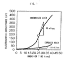
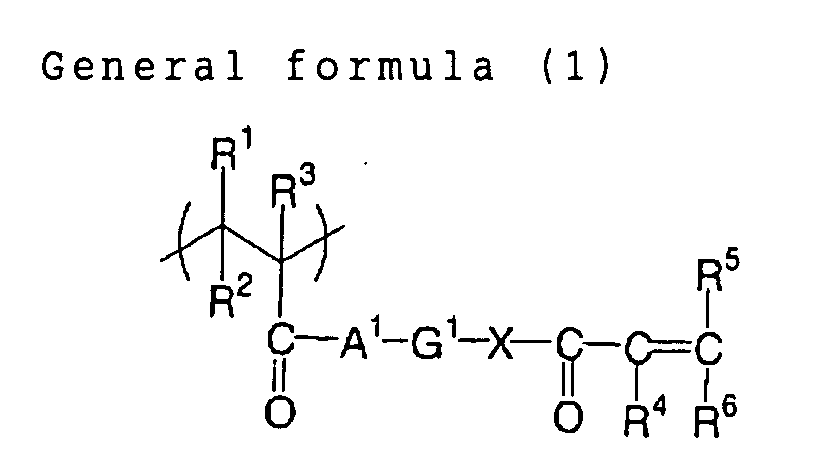


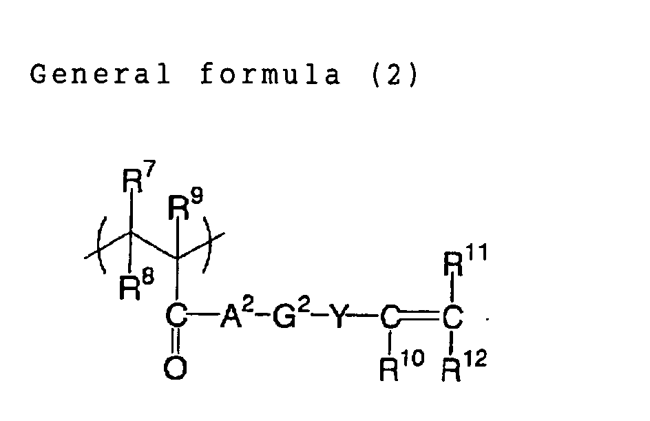

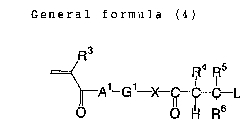


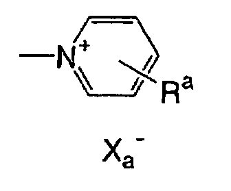
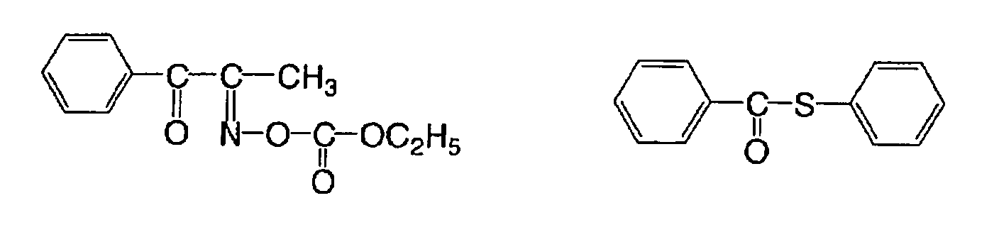

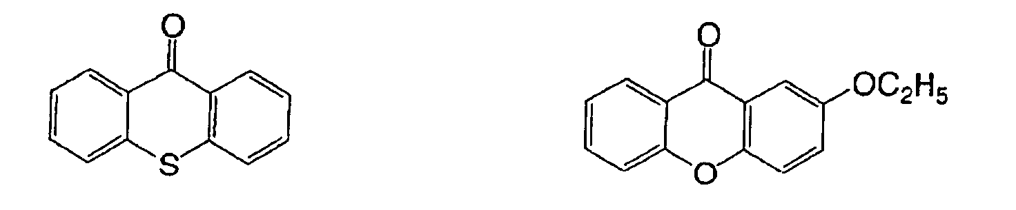
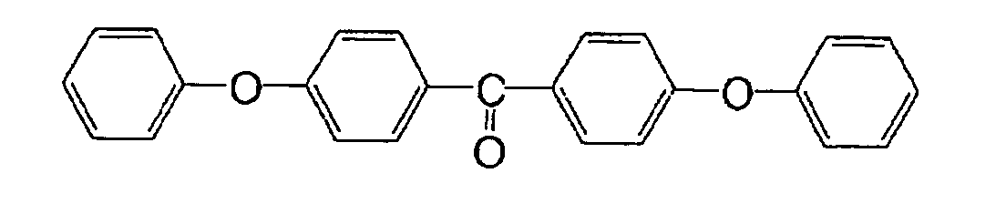

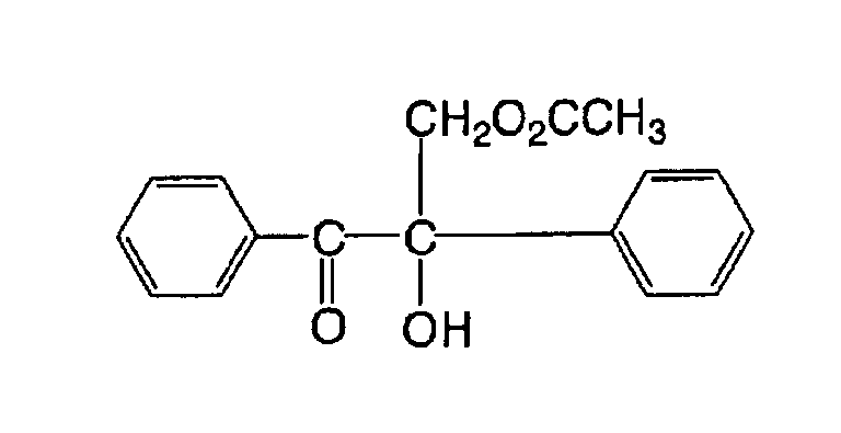
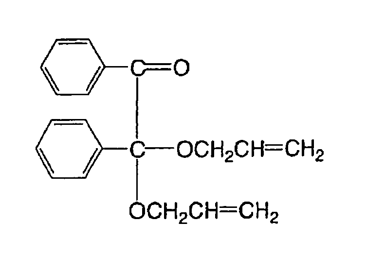

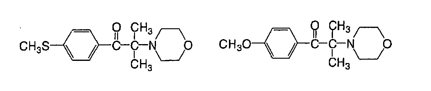
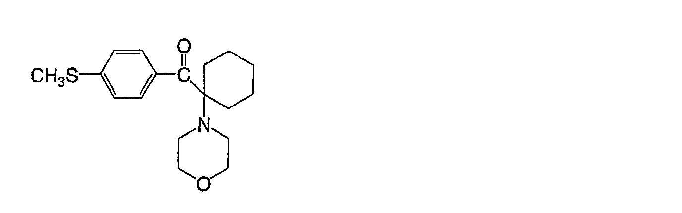
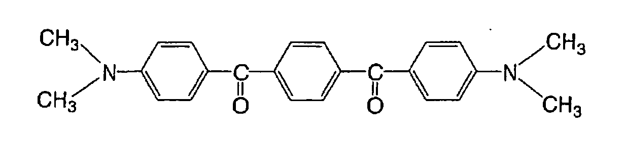
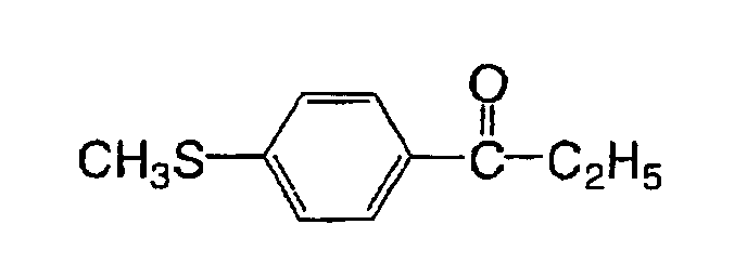
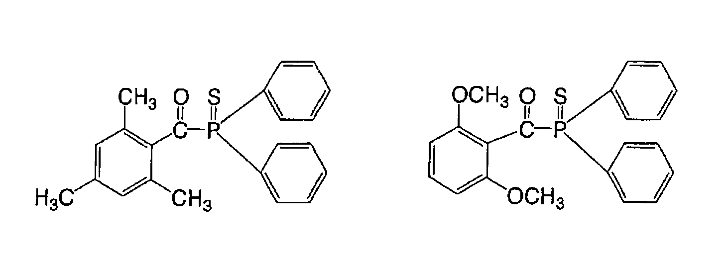
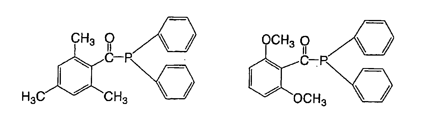
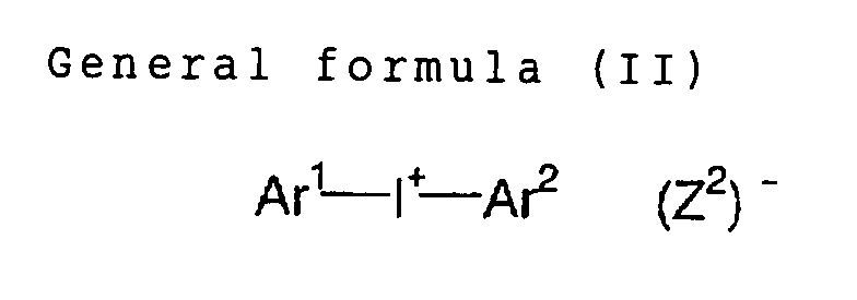
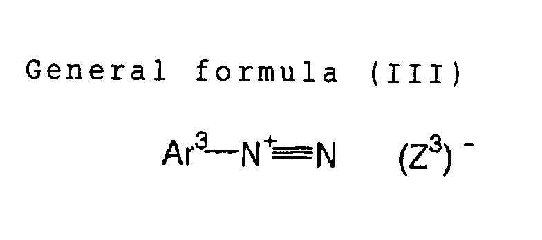
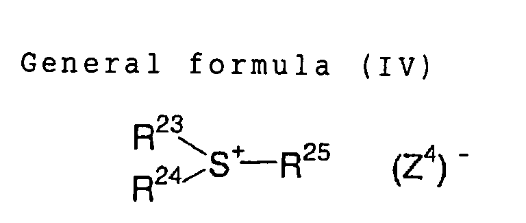


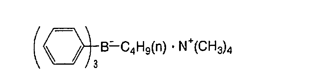
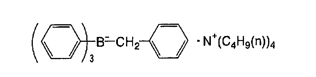


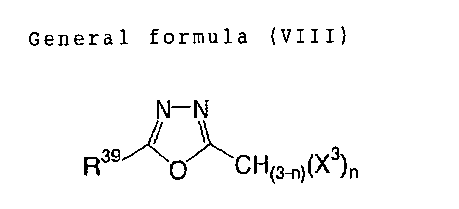
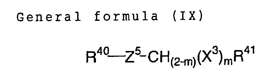
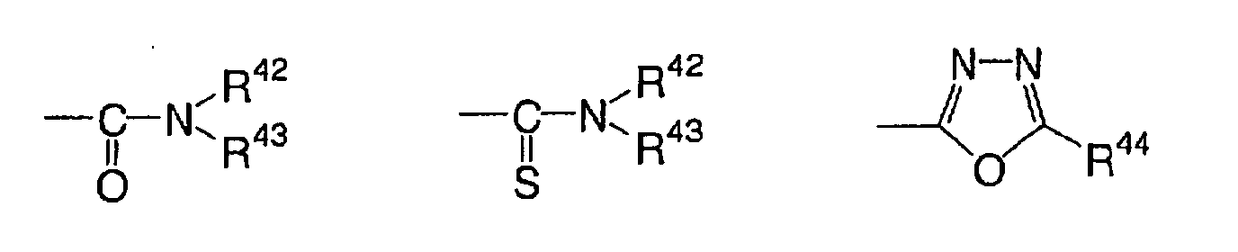
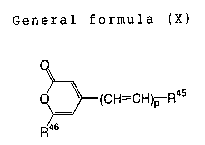


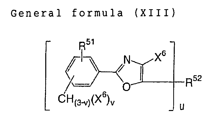
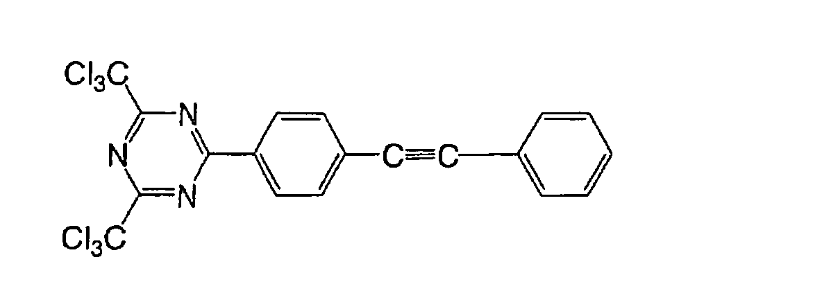
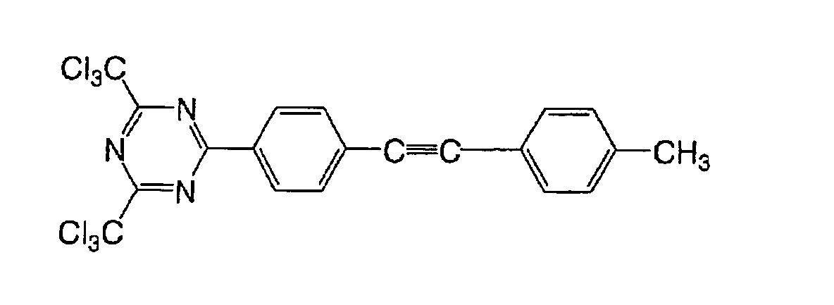
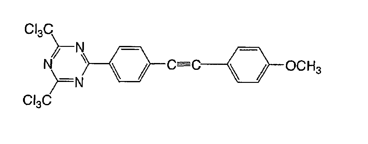
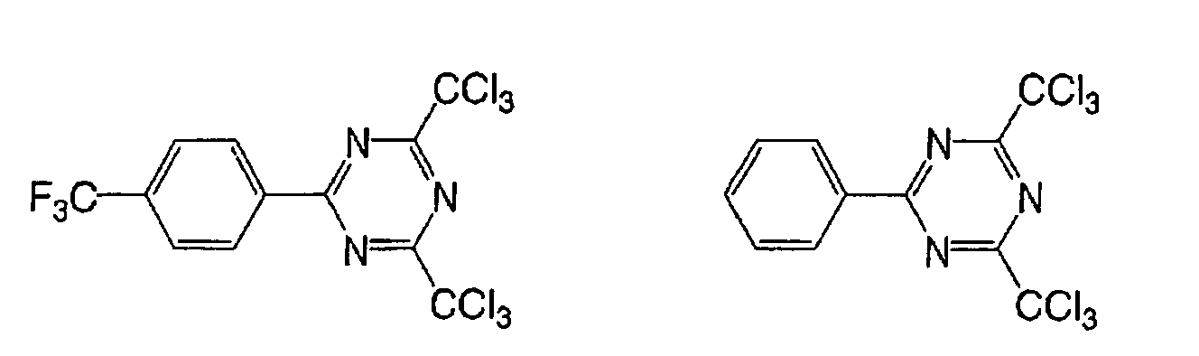

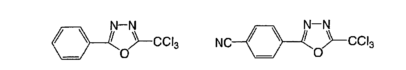
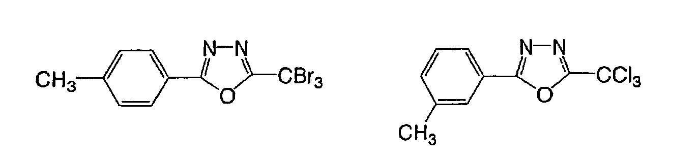
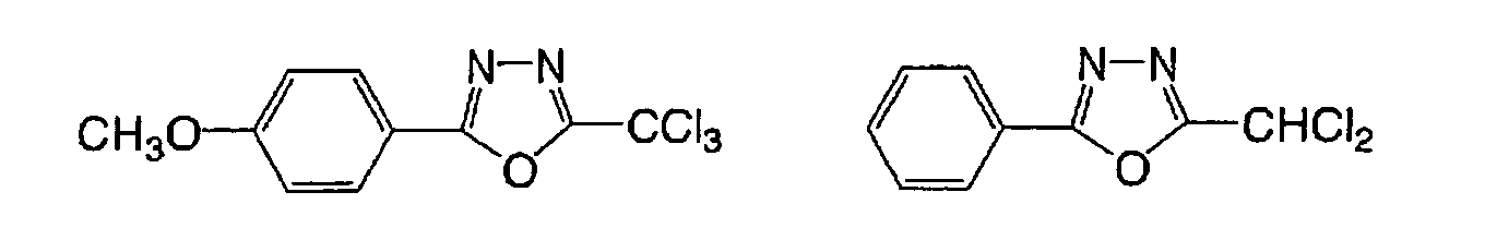

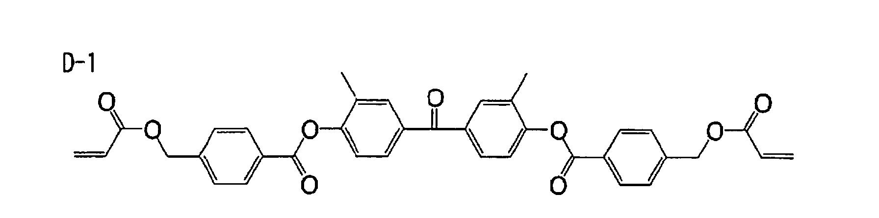
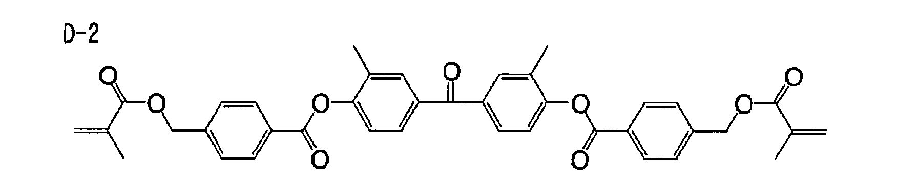

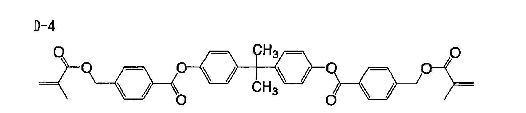
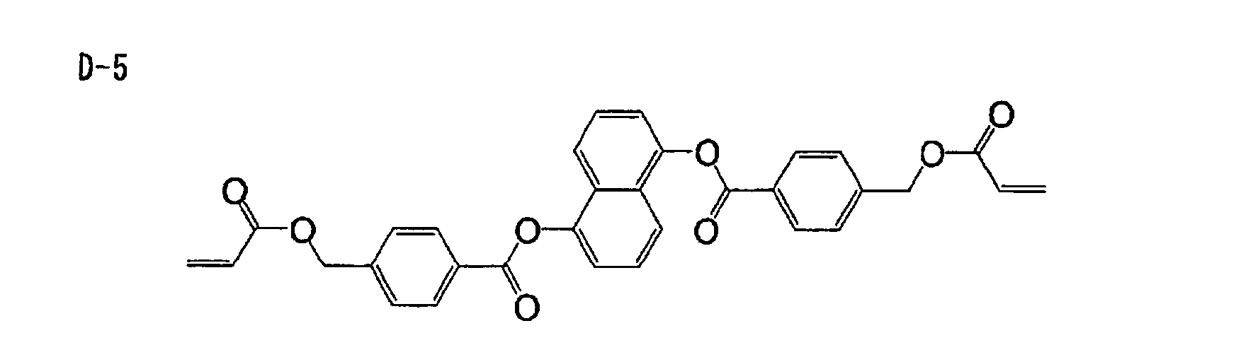
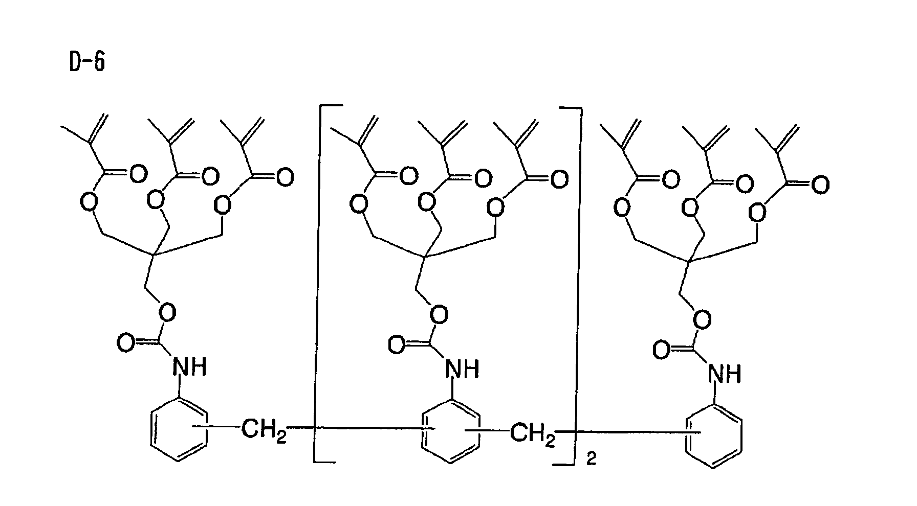
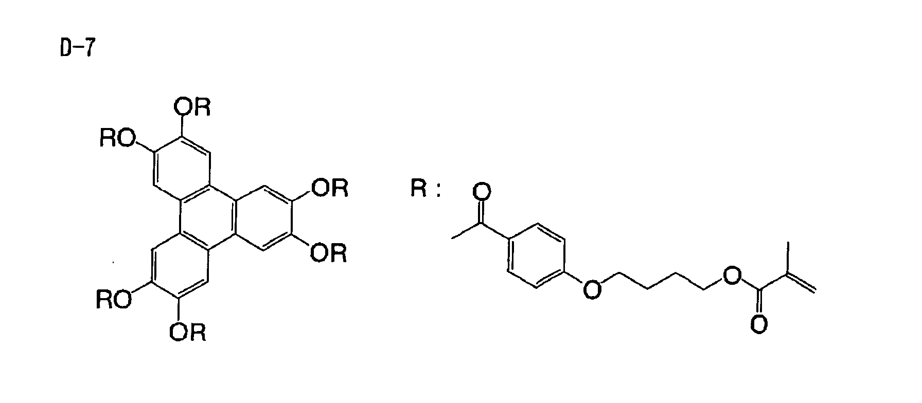

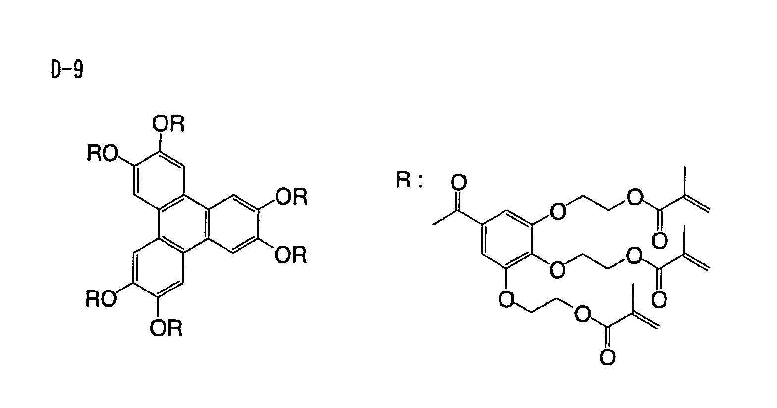
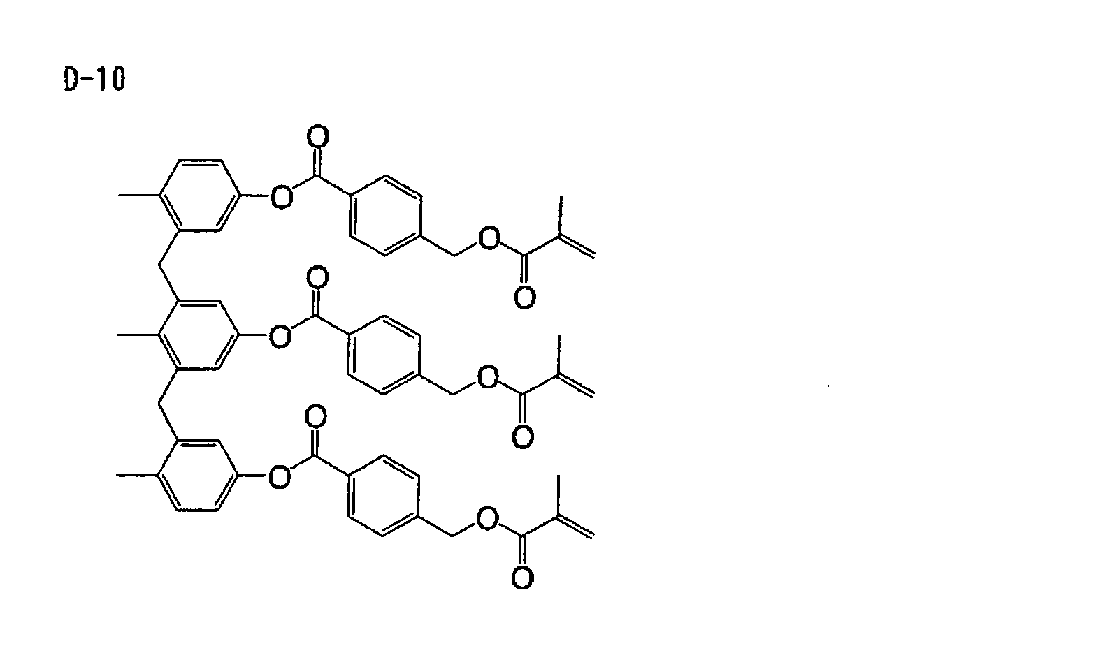


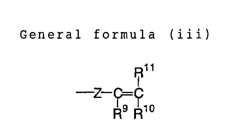
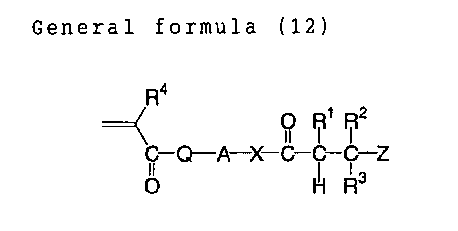
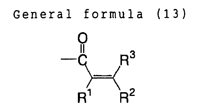

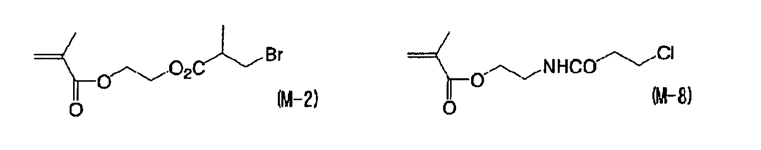


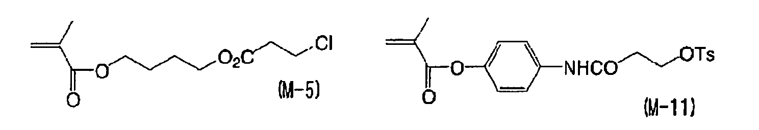

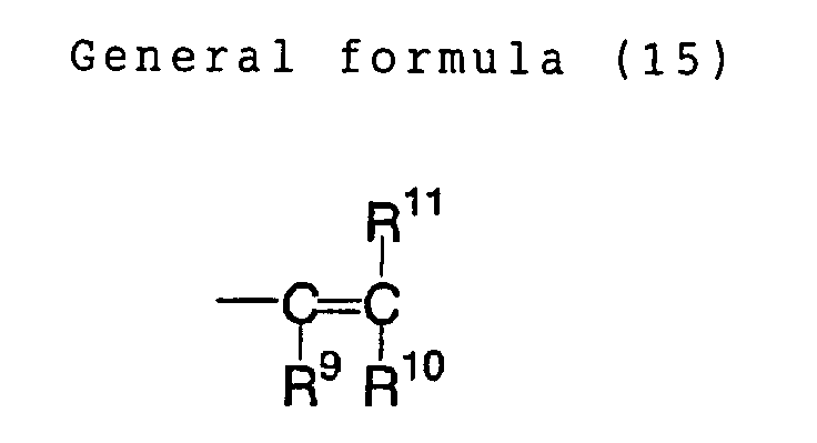
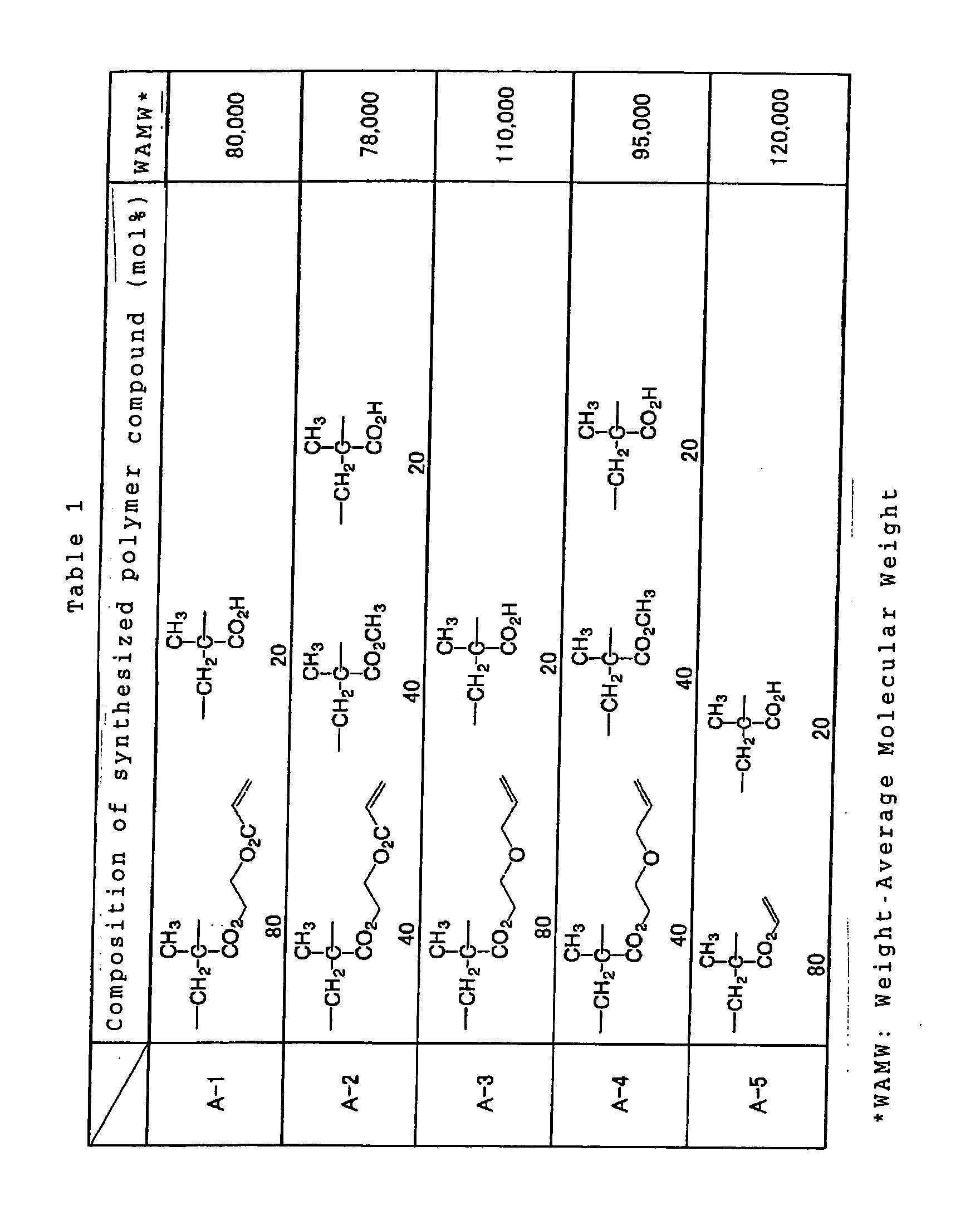
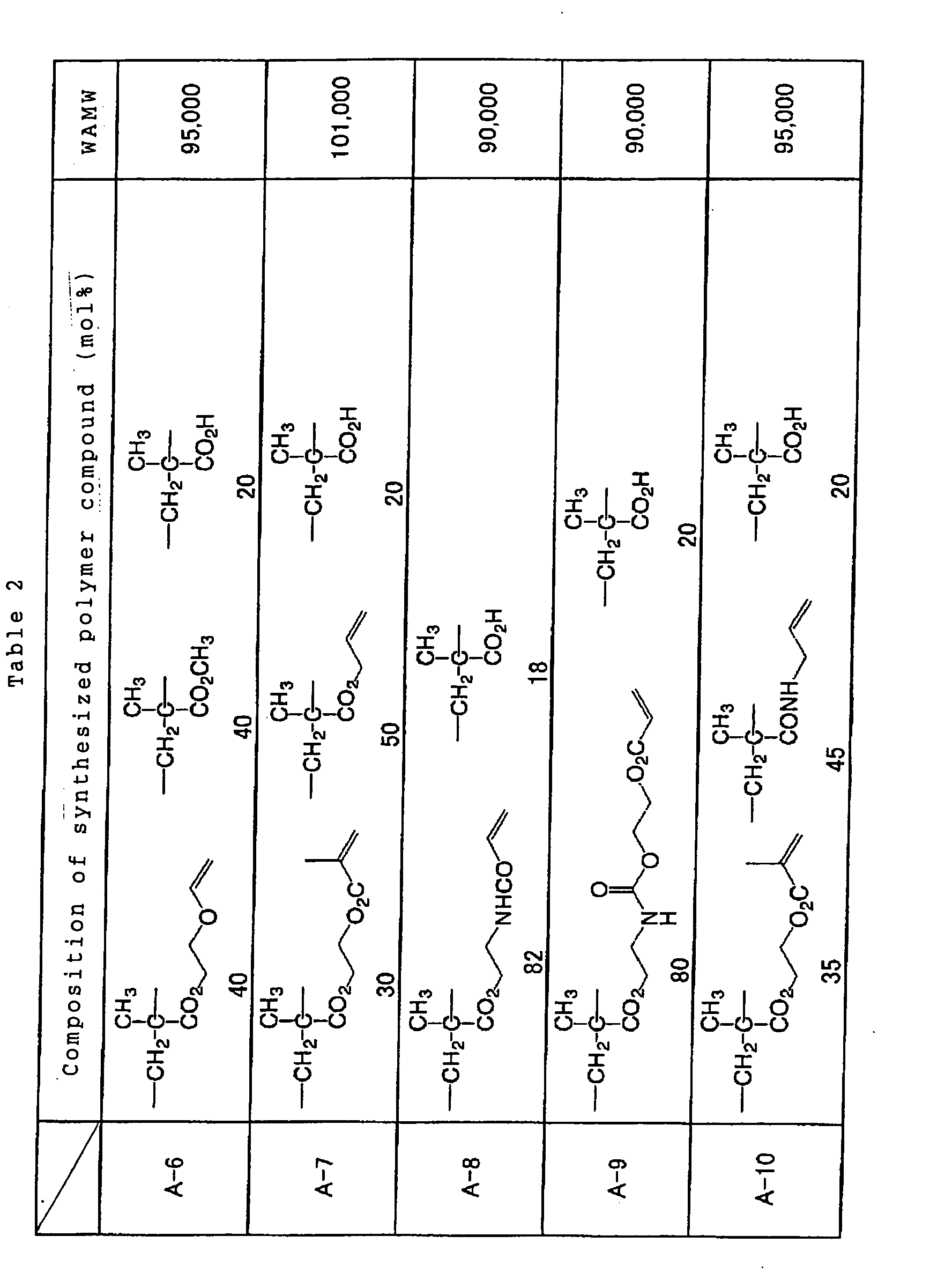
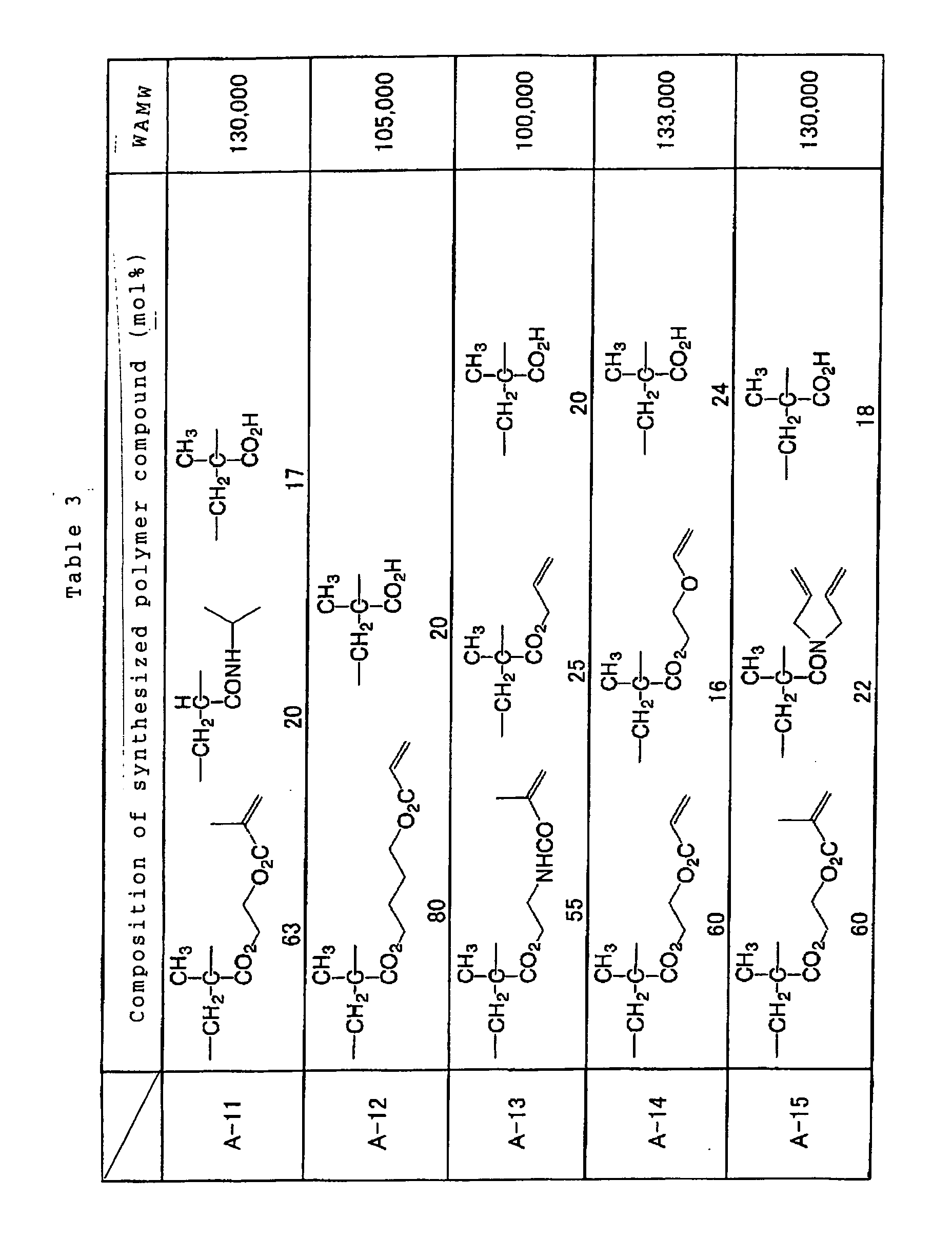
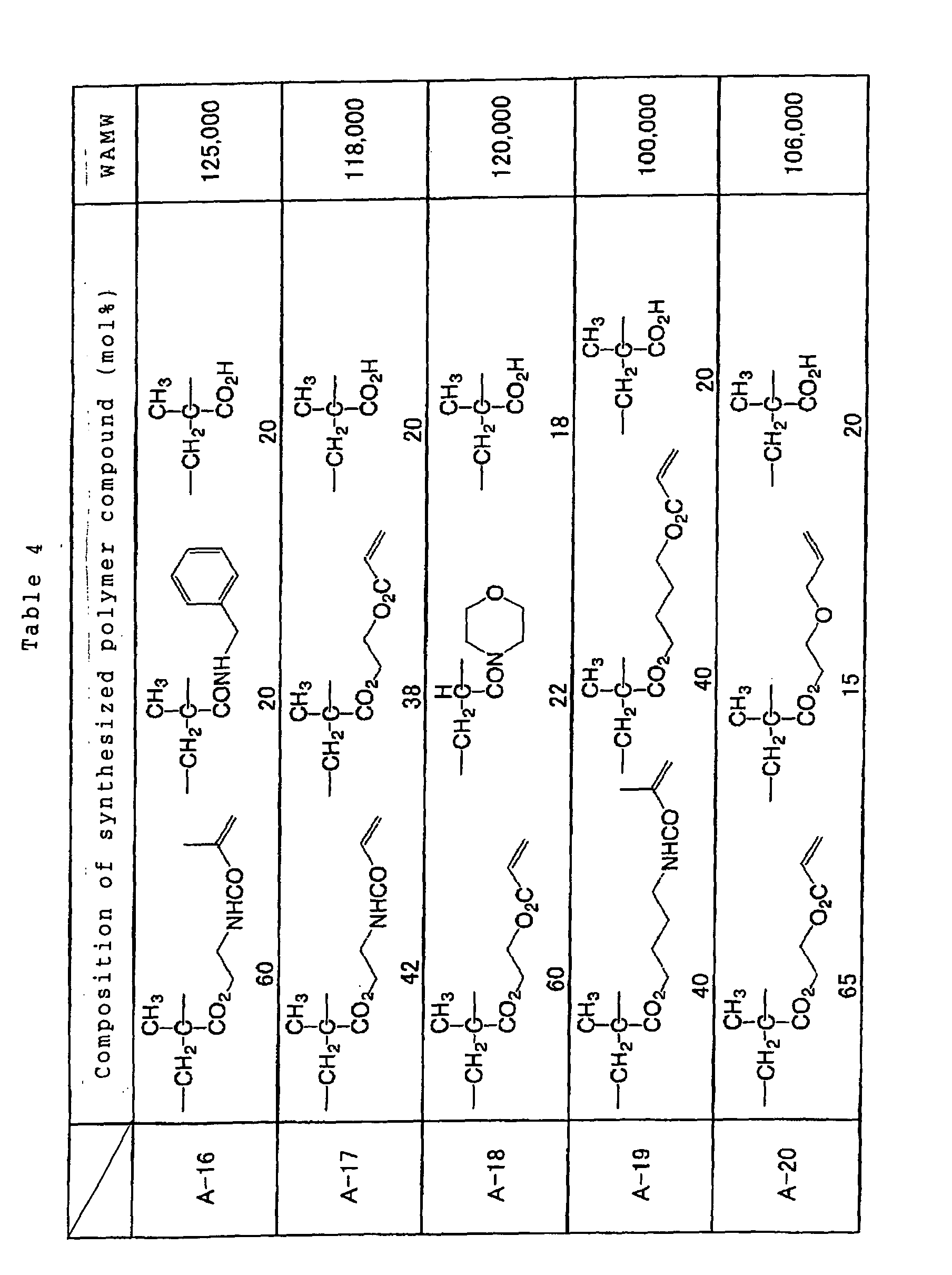
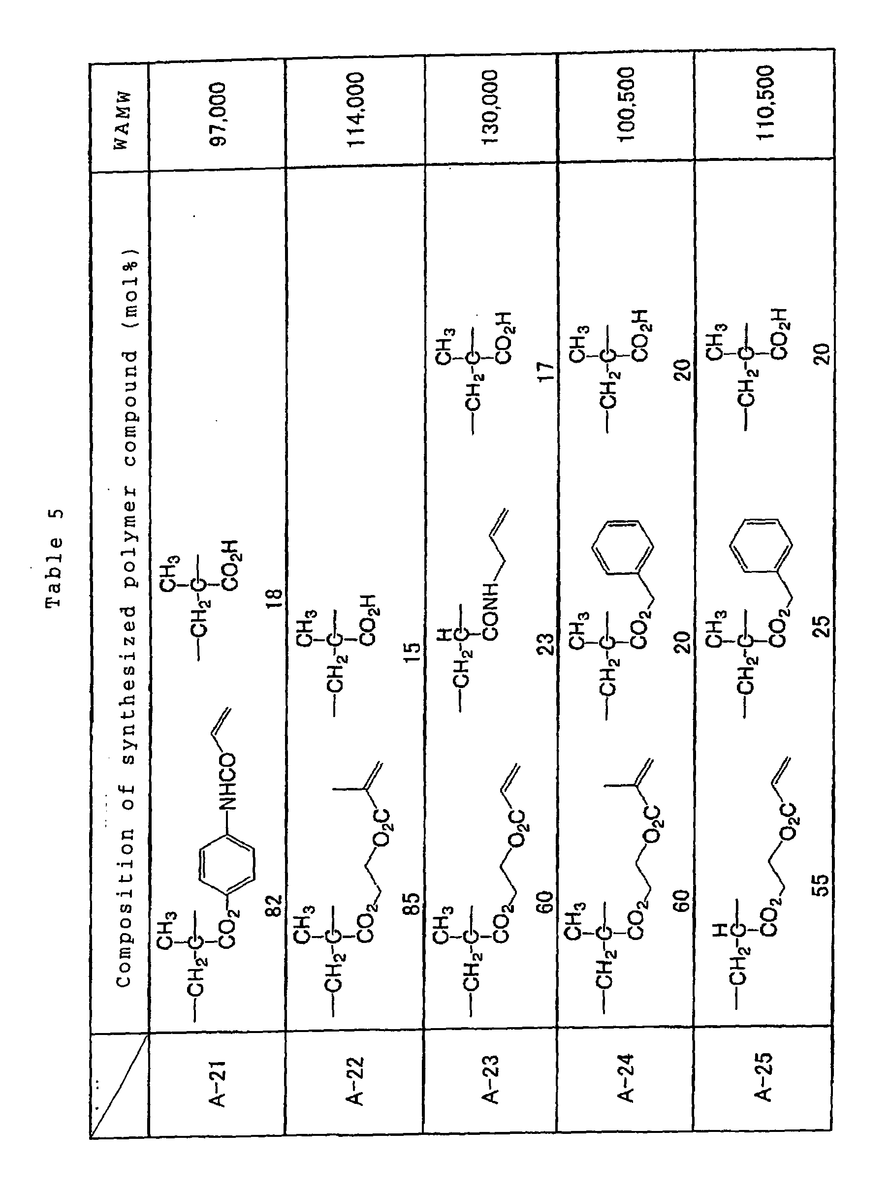

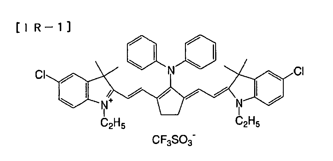
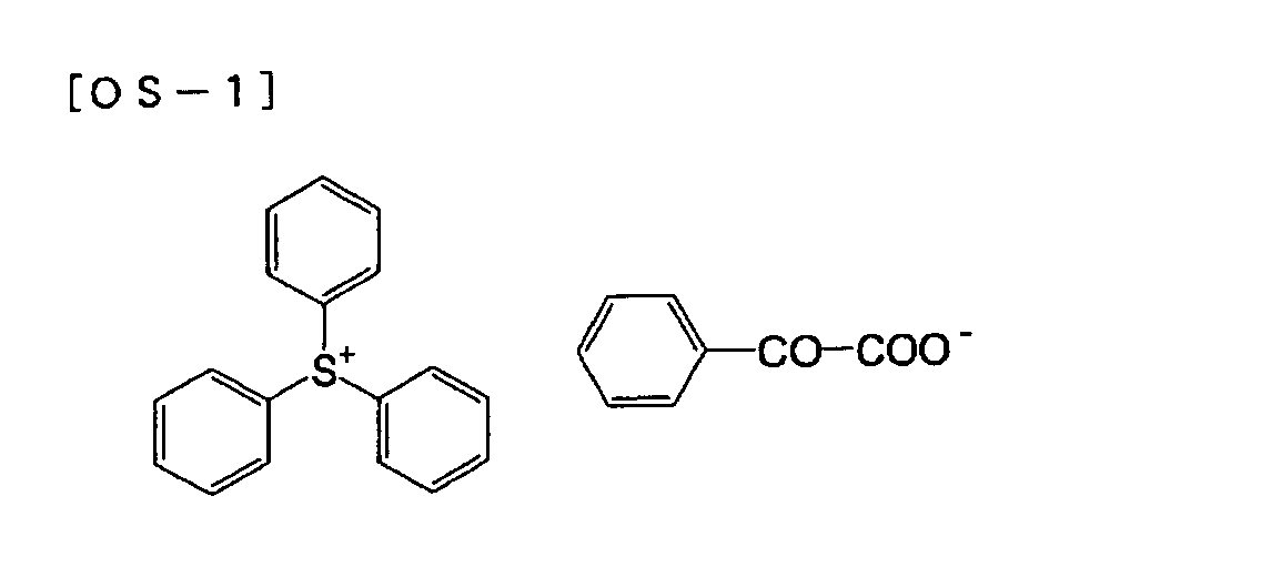


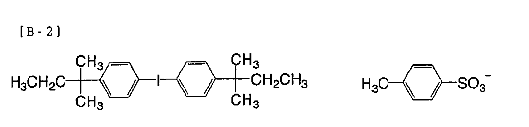

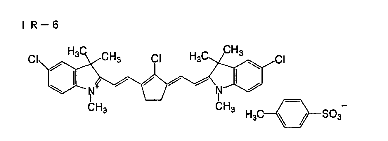
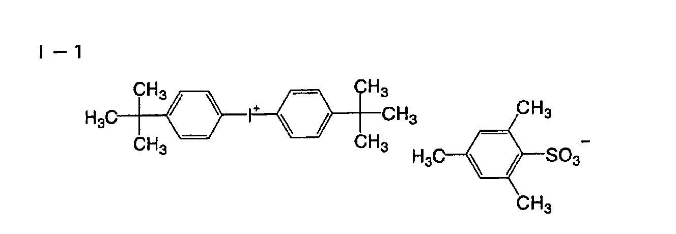


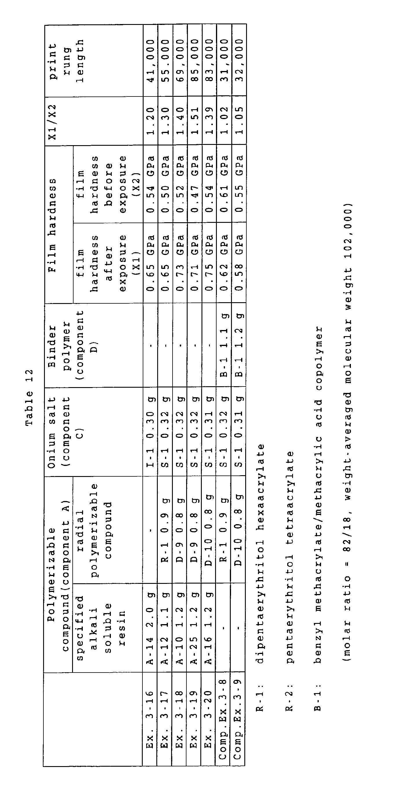
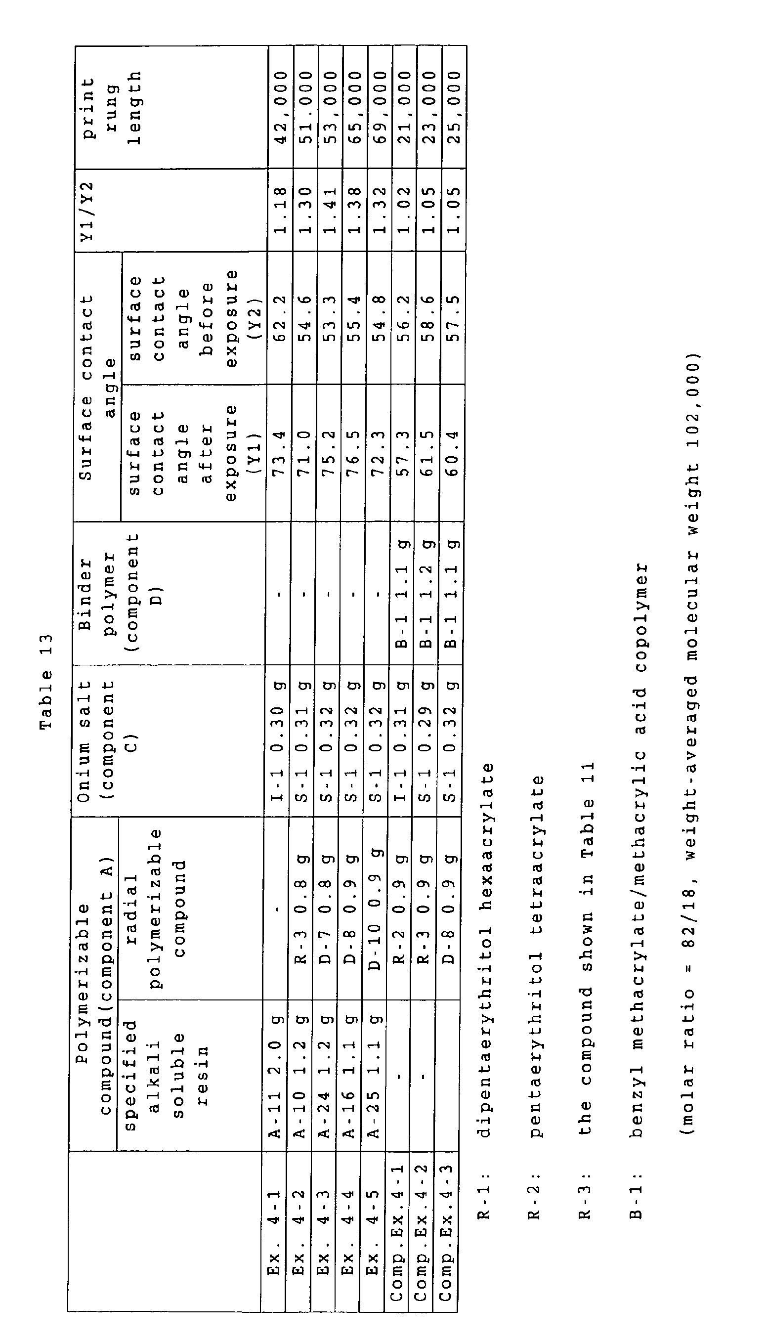

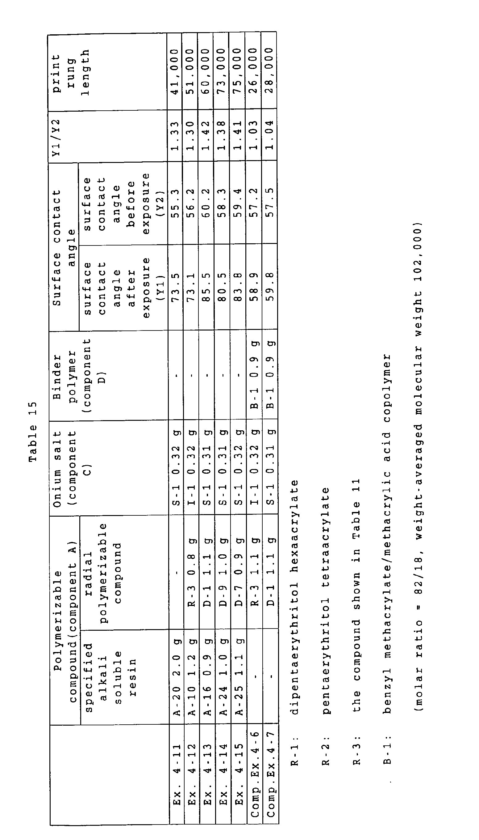

 wherein A1, A2 and A3 each independently represents an oxygen atom, a sulfur atom or -N(R21)-; R21 represents an alkyl group which may include substituents; G1, G2 and G3 each independently represents a divalent organic group; X and Z each independently represents an oxygen atom, a sulfur atom or -N(R22)-; R22 represents an alkyl group which may include substituents; Y represents an oxygen atom, a sulfur atom, a phenylene group which may include substituents, or -N(R23)-; R23 represents an alkyl group which may include substituents; and R1 to R20 each independently represents a monovalent organic group.