EP2854776B1 - System und verfahren zur synthese von mikropartikeln - Google Patents
System und verfahren zur synthese von mikropartikeln Download PDFInfo
- Publication number
- EP2854776B1 EP2854776B1 EP13726776.1A EP13726776A EP2854776B1 EP 2854776 B1 EP2854776 B1 EP 2854776B1 EP 13726776 A EP13726776 A EP 13726776A EP 2854776 B1 EP2854776 B1 EP 2854776B1
- Authority
- EP
- European Patent Office
- Prior art keywords
- microparticles
- phase
- dispersed
- nanoparticles
- dispersed phase
- Prior art date
- Legal status (The legal status is an assumption and is not a legal conclusion. Google has not performed a legal analysis and makes no representation as to the accuracy of the status listed.)
- Active
Links
Images







Classifications
-
- A—HUMAN NECESSITIES
- A61—MEDICAL OR VETERINARY SCIENCE; HYGIENE
- A61K—PREPARATIONS FOR MEDICAL, DENTAL OR TOILETRY PURPOSES
- A61K9/00—Medicinal preparations characterised by special physical form
- A61K9/14—Particulate form, e.g. powders, Processes for size reducing of pure drugs or the resulting products, Pure drug nanoparticles
-
- C—CHEMISTRY; METALLURGY
- C01—INORGANIC CHEMISTRY
- C01G—COMPOUNDS CONTAINING METALS NOT COVERED BY SUBCLASSES C01D OR C01F
- C01G49/00—Compounds of iron
- C01G49/02—Oxides; Hydroxides
-
- A—HUMAN NECESSITIES
- A61—MEDICAL OR VETERINARY SCIENCE; HYGIENE
- A61K—PREPARATIONS FOR MEDICAL, DENTAL OR TOILETRY PURPOSES
- A61K9/00—Medicinal preparations characterised by special physical form
- A61K9/48—Preparations in capsules, e.g. of gelatin, of chocolate
- A61K9/50—Microcapsules having a gas, liquid or semi-solid filling; Solid microparticles or pellets surrounded by a distinct coating layer, e.g. coated microspheres, coated drug crystals
- A61K9/5094—Microcapsules containing magnetic carrier material, e.g. ferrite for drug targeting
-
- B—PERFORMING OPERATIONS; TRANSPORTING
- B01—PHYSICAL OR CHEMICAL PROCESSES OR APPARATUS IN GENERAL
- B01F—MIXING, e.g. DISSOLVING, EMULSIFYING OR DISPERSING
- B01F23/00—Mixing according to the phases to be mixed, e.g. dispersing or emulsifying
- B01F23/40—Mixing liquids with liquids; Emulsifying
- B01F23/41—Emulsifying
- B01F23/4105—Methods of emulsifying
-
- B—PERFORMING OPERATIONS; TRANSPORTING
- B01—PHYSICAL OR CHEMICAL PROCESSES OR APPARATUS IN GENERAL
- B01F—MIXING, e.g. DISSOLVING, EMULSIFYING OR DISPERSING
- B01F23/00—Mixing according to the phases to be mixed, e.g. dispersing or emulsifying
- B01F23/40—Mixing liquids with liquids; Emulsifying
- B01F23/43—Mixing liquids with liquids; Emulsifying using driven stirrers
-
- B—PERFORMING OPERATIONS; TRANSPORTING
- B01—PHYSICAL OR CHEMICAL PROCESSES OR APPARATUS IN GENERAL
- B01F—MIXING, e.g. DISSOLVING, EMULSIFYING OR DISPERSING
- B01F23/00—Mixing according to the phases to be mixed, e.g. dispersing or emulsifying
- B01F23/80—After-treatment of the mixture
- B01F23/804—Drying the mixture
-
- B—PERFORMING OPERATIONS; TRANSPORTING
- B01—PHYSICAL OR CHEMICAL PROCESSES OR APPARATUS IN GENERAL
- B01F—MIXING, e.g. DISSOLVING, EMULSIFYING OR DISPERSING
- B01F27/00—Mixers with rotary stirring devices in fixed receptacles; Kneaders
-
- B—PERFORMING OPERATIONS; TRANSPORTING
- B01—PHYSICAL OR CHEMICAL PROCESSES OR APPARATUS IN GENERAL
- B01F—MIXING, e.g. DISSOLVING, EMULSIFYING OR DISPERSING
- B01F35/00—Accessories for mixers; Auxiliary operations or auxiliary devices; Parts or details of general application
- B01F35/71—Feed mechanisms
- B01F35/712—Feed mechanisms for feeding fluids
-
- B—PERFORMING OPERATIONS; TRANSPORTING
- B01—PHYSICAL OR CHEMICAL PROCESSES OR APPARATUS IN GENERAL
- B01J—CHEMICAL OR PHYSICAL PROCESSES, e.g. CATALYSIS OR COLLOID CHEMISTRY; THEIR RELEVANT APPARATUS
- B01J13/00—Colloid chemistry, e.g. the production of colloidal materials or their solutions, not otherwise provided for; Making microcapsules or microballoons
- B01J13/02—Making microcapsules or microballoons
- B01J13/04—Making microcapsules or microballoons by physical processes, e.g. drying, spraying
- B01J13/043—Drying and spraying
-
- B—PERFORMING OPERATIONS; TRANSPORTING
- B01—PHYSICAL OR CHEMICAL PROCESSES OR APPARATUS IN GENERAL
- B01J—CHEMICAL OR PHYSICAL PROCESSES, e.g. CATALYSIS OR COLLOID CHEMISTRY; THEIR RELEVANT APPARATUS
- B01J13/00—Colloid chemistry, e.g. the production of colloidal materials or their solutions, not otherwise provided for; Making microcapsules or microballoons
- B01J13/02—Making microcapsules or microballoons
- B01J13/06—Making microcapsules or microballoons by phase separation
- B01J13/12—Making microcapsules or microballoons by phase separation removing solvent from the wall-forming material solution
- B01J13/125—Making microcapsules or microballoons by phase separation removing solvent from the wall-forming material solution by evaporation of the solvent
-
- H—ELECTRICITY
- H01—ELECTRIC ELEMENTS
- H01F—MAGNETS; INDUCTANCES; TRANSFORMERS; SELECTION OF MATERIALS FOR THEIR MAGNETIC PROPERTIES
- H01F1/00—Magnets or magnetic bodies characterised by the magnetic materials therefor; Selection of materials for their magnetic properties
- H01F1/0036—Magnets or magnetic bodies characterised by the magnetic materials therefor; Selection of materials for their magnetic properties showing low dimensional magnetism, i.e. spin rearrangements due to a restriction of dimensions, e.g. showing giant magnetoresistivity
- H01F1/0045—Zero dimensional, e.g. nanoparticles, soft nanoparticles for medical/biological use
- H01F1/0054—Coated nanoparticles, e.g. nanoparticles coated with organic surfactant
-
- B—PERFORMING OPERATIONS; TRANSPORTING
- B01—PHYSICAL OR CHEMICAL PROCESSES OR APPARATUS IN GENERAL
- B01F—MIXING, e.g. DISSOLVING, EMULSIFYING OR DISPERSING
- B01F35/00—Accessories for mixers; Auxiliary operations or auxiliary devices; Parts or details of general application
- B01F35/90—Heating or cooling systems
- B01F2035/99—Heating
-
- C—CHEMISTRY; METALLURGY
- C01—INORGANIC CHEMISTRY
- C01P—INDEXING SCHEME RELATING TO STRUCTURAL AND PHYSICAL ASPECTS OF SOLID INORGANIC COMPOUNDS
- C01P2004/00—Particle morphology
- C01P2004/60—Particles characterised by their size
- C01P2004/61—Micrometer sized, i.e. from 1-100 micrometer
-
- C—CHEMISTRY; METALLURGY
- C01—INORGANIC CHEMISTRY
- C01P—INDEXING SCHEME RELATING TO STRUCTURAL AND PHYSICAL ASPECTS OF SOLID INORGANIC COMPOUNDS
- C01P2006/00—Physical properties of inorganic compounds
- C01P2006/42—Magnetic properties
Definitions
- the present specification relates to system and method for the synthesis of microparticles having controllable size and morphology.
- SMPs Superparamagnetic microparticles
- SMPs have been widely used for bioseparation applications, for example, in point of care testing, diagnstoics, and high through screening, due to the speed, ease, efficiency, and cost effective nature of magnetic separation.
- These particles are used in a number of biomedical appplicaitons, for example, in vivo imaging with magnetic resonance imaging and targeted drug delivery, due to their response to electromagentic radiation .
- These micro-particles are normally coated with a polymer that stabilizes them in aqueous solution and provides chemical groups to which biomolecules, such as, DNA and proteins can be conjugated.
- Commercially available SMPs defined as particles over 30 nm in diameter, are typically spherical and composed of an assembly of, for example, metal oxide superparamagnetic nanoparticles.
- the nanoparticles have been distributed in a polymer microparticle matrix or self-assembled to form a tightly packed spherical SMP without the addition of a polymer component.
- an emulsification method was used for example often a crude emulsion was first prepared by manually stirring the two phases together and then pumped into a mixing device. Fragmentation of the crude emulsions took place within the device and the homogenized emulsion emanated through an outlet port.
- This emulsion synthesis method can be problematic due to the inconsistencies in the premixing step potentially leading to the formation of very small droplets and limited throughput time due to the phase separation of the metastable premixed emulsions.
- hollow SMPs consisting of iron oxide nanoparticles embedded in polystyrene have been fabricated using, for example, an inverse microemulsion polymerization process.
- the surfaces of the nanoparticles have been made amphiphilic through functionalization with both active hydrophilic hydroxyl groups and hydrophobic oleic ester groups.
- the amphiphilic nanoparticles could then be used as colloidal stabilizers for inverse water-in-oil emulsions and also mediated the polymerization of styrene monomers in the oil phase at the droplet interface to form a hollow polystyrene iron oxide composite SMP up to a couple of micrometers in diameter.
- hollow and porous Gd 2 O 3 microspheres have been synthesized through the deposition of superparamagnetic material together with a polymer on the surface of or within a spherical gelatin template, which was later removed using calcination leaving behind a hollow or porous SMP roughly 100 or 200 nm in diameter, respectively.
- polymer-iron oxide composite SMPs have been synthesized using water-oil-water double emulsions in which the middle oil phase consists of a mixture of both a liquid pre-polymer and superparamagnetic nanoparticles.
- polymer magnetite iron oxide SMPs with a hollow hemispherical morphology 12 ⁇ m in diameter were formed.
- These methods for the production of SMPs involve a large number of steps such as the removal of a sacrificial template on which the superparamagnetic material has been deposited or incorporate a polymeric material, which often reduces the magnetic moment of the resulting SMPs.
- the present specification provides an improved method and system for producing microparticles and superparamagnetic microparticles that aims to address problems including the above noted problems with existing methods and systems for producing microparticles.
- the system and method of the present specification provide for scalable production.
- the system and method also provide for improved uniformity of microparticle size and control of size and type of microparticle.
- the present specification also provides improved microparticles having controllable size and morphology.
- the method and system described provide production of particles having high surface area to volume ratio and therefore high binding capacity.
- a process is described that results in a highly simplified production of the magnetic particles resulting in a decreased cost of production.
- the present specification also provides a method for producing magnetic particles of tuneable magnetisation and, for example, having high magnetic mobility.
- shear device 10 as defined in claim 15.
- the present specification describes a system and method for the production of microparticles via emulsion based synthesis or emulsion template self assembly.
- the method addresses the above noted problems and provides an improved control over the steps of mixing and emulsification and drying to provide for the reproducible synthesis of microparticles with the desired size and morphology as required for different applications.
- the arrangement of system and the method provide for scalable production of microparticles. Further the system and method provide for the production of microparticles of improved uniformity of size and different morphologies.
- microparticles According to the method of the present specification various alternative forms of microparticles have been produced including spherical microparticles and dimpled, crumpled porous and hollow microparticles.
- the method provides for production of particles of tuneable magnetisation. Accordingly, the method provides for production of particles for use in multiplex applications.
- the method provides for production of monodisperse particles having a coefficeint of variance (CV) of diameter of ⁇ 25%.
- CV coefficeint of variance
- the method provides for production of microparticles of controlled morphology including dimpled and crumpled microparticles having magnetic velocities and surface area to volume ratios different from spherical microparticles of similar size.
- the method provides for production of microparticles of controlled morphology further including porous and hollow microparticles.
- the system 1 comprises a shear device 10 connected to a drying device 20.
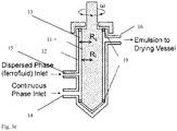
- the shear device 10 comprises a housing having separate inlets 14 and 15 for a first fluid phase and a second fluid phase and an emulsion outlet 16.
- the inlets 14 and 15 are connected to first and second fluid phase reservoirs 17 and 18.
- the first fluid phase is a continuous phase 30 and the second fluid phase is a dispersed phase 40 which comprises a dispersed material 41.
- the dispersed material comprises a superparamagnetic material for example, superparamagnetic nanoparticles.
- An emulsion 50 is formed in the shear device 10 by mixing the continuous and dispersed phases 30 and 40.
- the emulsion 50 is provided via the emulsion outlet 16 to the drying device 20 for drying.
- the emulsion outlet 16 is located to the upper side of the shear device 10. It is significant that the emulsification occurs in the shear device as the first and second phases enter and are mixed therein.
- the continuous phase 30 is an aqueous phase or oil phase immiscible with the dispersed phase.
- the dispersed phase 40 comprises material for producing the microparticles.
- the dispersed phase 40 includes dispersed material 41.
- the dispersed material 41 may for example, be a polymer or nanoparticles. Further, the dispersed phase may be combination thereof. Further the dispersed phase may comprise a third component such as fluorescent material, or encapsulated drug. In effect, the dispersed phase may contain any component which is desired to be included in the resulting microparticles.
- the dispersed phase may comprise a polymer solution or a nanoparticle suspension. The material - polymer or nanoparticles is provided to produce the microparticles.
- Nanoparticles in the dispersed phase may be metal oxide nanoparticles or any type of superparamagnetic nanoparticle.
- the nanoparticles in the dispersed phase may most preferably comprise iron or iron oxide nanoparticles.
- the nanoparticles may also comprise Ni or PtFe.
- the use of iron oxide nanoparticles, for example, Fe 2 O 3 , Fe 3 O 4 or a mixture thereof, enables production of microparticles with a tuneable magnetisation and a high magnetic susceptibility.
- the magnetisation may be in the range of 20 to 110 Am 2 /kg (20-110 emU/g).
- the magnetisation may be in a preferred range of 20 to 80 Am 2 /kg (20-80 emU/G).
- the phases are not premixed. Emulsification occurs upon entry of the first and second phases to the shear device.
- the emulsifying step occurs as the first and second phases enter the shear device.
- the mixing step includes an emulsifying step as the second dispersed phase is emulsified into the first continuous phase in the shear device.
- the phases 30 and 40 are mixed in the shear device 10 to form the emulsion 50 comprising emulsion droplets 51.
- the shear device 10 includes a rotor 11 configured to revolve inside a stationary stator 12. A gap 13 is provided between the rotor 11 and stator 12. The gap 13 is an annular gap. Emulsification of the phases occurs in the gap 12.
- the shear device 10 is configured to provide control of the droplet size distribution in the emulsion 50. The shear device is controlled and the operating parameters of the shear device 10 may be varied and controlled to control the droplet size and uniformity of size distribution. The shear device is arranged to provide a uniform force therein.
- the droplet size is less than 50microns.
- the droplet size is preferably less than 20microns. Depending on requirements, the droplet size may be less than 10microns.
- the particle size distribution is controlled by optimising the features of the radius of the rotor 11.
- the particle size distribution is also controlled by optimising the gap size between the rotor 11 and stator 12.
- the gap size is set at substantially 100 microns.
- a shear device having different suitable gap size depending on requirements may also be provided.
- the rotor is controlled to rotate inside the stationary stator. Rotation speeds of up to 2000 rpm may be applied, in general the device is operated at rates between 50 and 1000 or 50 and 1500 rpm depending on requirements.
- the rotor 11 has a radius substantially of the order of 20cm. Referring to Fig. 3e the provision of rotor of relatively large radius R i provides for improved control of rotor rotation including speed and for increased speed of rotation.
- Viscosity of the continuous phase is important and viscosity of the continuous phase may be controlled by controlling selection of surfactant, surfactant concentration and thickening material which are selected and used at concentrations, as required.
- the shear device 10 further comprises control means for controlling the rotation speed of the rotor 11 and control means for controlling the flow rate of the continuous phase 30 and the dispersed phase 40 to the shear device 10. Control of the flow rates provides control of - dispersed phase volume fraction.
- the arrangement of the shear device with two separate inlet ports for the different phases provides for a high level of control of the dispersed phase volume fraction.
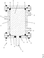
- a shear device 10 according to an arrangement of the present specification is shown.
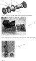
- Figs. 3d and 3e alternative shear devices 10 are shown having bearings 19 provided to maintain the gap size between the rotor 11 and stator 12 in the arrangement shown.
- a shear device 10 according to the present specification was provided having a cylindrical rotor 11 of substantially 45 mm in diameter with stainless steel ball beads 19 fitted on either end.
- the housing 10a comprises a cylindrical stator 12 with flanges on either end.
- the gap (R 0 -R i ) 13 between the inner radius of the stator 12 and the outer radius of the rotor 11 is substantially 100 ⁇ m.
- Two circular plates 34 are bolted using bolts 30 onto either end of the stator 12, pressing against the bearings 19 to keep them tightly positioned and minimise undesired movement.
- the rotor 11 has a cylindrical shaft on one side which is coupled to a motor via coupling 33.
- One of the plates 34 has a hole in its centre through which the shaft passes.
- a u-ring 31 is used to prevent leakage from the device through the gap in the plate around the shaft.
- O-rings 32 are also provided.
- Couette shear mixer showing individual inlets for aqueous and dispersed phases, with emulsion outlet on top right.
- the shear device 10 is configured to provides for scalability, and/or for large throughput and/or large scale production of microparticles, as follows:
- the above noted features are selected and optimised to provide for production of substantially uniform microparticles.
- the system and method provide for production of monodisperse particles of %CV of 25% preferably substantially ⁇ 25% CV.
- the shear device 10 has been configured to advantageously provide consistent shear rate and improved throughput.
- the shear device 10 is configured to provide a minimised particle size distribution by optimisation of critical parameters.
- Optimisation of method and system for control of droplet/microparticle size and uniformity of size distribution include control of the following:
- the device is operable at shear rates of up to 2000 revoluions per minute (rpm), preferably in the range of 50- 1500 rpm.
- rpm revoluions per minute
- operation has been optimised as follows: For production of spherical particles for example of 350 nm, shear rate is controlled to provide a shear rate of substantially 300 rpm (6900 per sec) or greater. For production of Crumpled /dimpled particles shear rate is controlled to provide a shear rate preferably of 50-100 rpm. For production of porous particles a shear rate in the range of 50-800 rpm is preferably used.
- Dispersed phase volume fraction is controlled to provide a dispersed phase volume fraction in the range of 10-90%.
- a dispersed phase volume fraction above 50% preferably 80% is used.
- a dispersed phase volume fraction of preferably 10-50%, preferably 30-50% is used.
- Viscosity ratio between phases dispersed to continuous is controlled to between 0.01 and 1, most preferably 0.1.
- Surfactant concentration is controlled in the range of 0.1 to 10%.
- the surfactant may for example comprise SDS, TX100. Tween 20.
- a surfactant concentration to the lower end of the range may be preferred.
- a concentration of 0.1% may be used.
- Continuous phase viscosity is controlled by selection of thickener.
- Thickeners may include@ Dextran, PVP, Sucrose, (hydrophilic/non-absorbing polymer).
- Continuous phase viscosity is controlled by selection of surfactant. Concentration of thickener and/or surfactant is selected and controlled as required.
- the method further provides for control of magnetisation of microparticles, by control of type and concentration of superparamagnetic microparticles provided in the dispersed phase.
- the superparamagnetic particles may comprise iron oxide nanoparticles for example, Fe 3 O 4 nanoparticles or Fe 2 O 3 nanoparticles or a mixture thereof.
- Fe 3 O 4 nanoparticles, Fe 2 O 3 nanoparticles have lower magnetic susceptibility and saturation magnetisation and SMPs produced using mixtures of Fe 3 O 4 and Fe 2 O 3 nanoparticles.
- Fig. 6 it is noted that the use of iron oxide nanoparticles 41 enables production of microparticles 100 with a tuneable magnetisation and a high magnetic susceptibility.
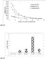
- Figs. 4 and 5a and 5b the effects of varying shear rate and different disperse phase volume fractions are illustrated in graphical form.
- the shear device 10 is further connected to the drying device 20 for having control means for drying the emulsion droplets 51, as required.
- the drying device is a drying bath 20 having control means for controlling drying including for example the drying rate.
- Microparticles 100 of a particular required morphology are formed by controlling parameters including:
- microparticles 100 of different morphologies for example, spherical, crumpled, dimpled or porous or hollow may be formed as required by suitable control of one or more of the above parameters.
- Nanoparticle concentration is controlled preferably in the range of 0.1 to 200 mg/ml is used. Concentrations of 0.1-0.5 mg/ml may be preferably used for the production of crumpled or dimpled microparticles. Concentrations of 80 mg/ml may preferably be used for the production of hollow/porous microparticles.
- the surface chemistry of oleic acid ligands on the surface of the nanoparticles is controllable to produce microparticles of crumpled morphology. Discussed further below with reference to Fig. 12 and examples.
- the rate of drying is controllable to control the formation of microparticles of different morphology.
- the drying bath 20 is an enclosed drying bath.
- the drying bath 20 includes heating means 22 and an agitation means, the agitation means is for example an impellor 23 for mixing the emulsion 50 in the drying bath.
- the drying bath 20 has control means 21 for controlling the temperature. In the case of the drying bath 20 it is possible to vary the temperature substantially between 5 and 80 degrees Celsius. As the drying bath is enclosed it is possible to control the dispersed phase vapour pressure during drying.
- the impellor 23 is controlled to control mixing to vary the impellor mixing speed.
- the impellor is operable up to a mixing speed of 400 RPM.
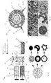
- Fig. 8 shows images of particles of different morphologies formed according to a method of the present specification.
- the continuous phase 10 is an aqueous phase.
- the continuous phase 10 further includes a surfactant 11, for example SDS, TX-100, Tween 20 and a thickener 12, for example Dextran, PVP, Sucrose (hydrophilic/ non-absorbing polymer).
- the dispersed phase 20 comprises a nanoparticle suspension.
- the nanoparticles 41 are particles having dimensions of the order of 10nm.
- the nanoparticles 41 of an exemplary arrangement of the present specification as described comprise iron oxide or Fe 3 O 4 or Fe 2 O 3 nanoparticles.
- the dispersed phase 40 comprises nanoparticles 41 of Fe 3 O 4 dissolved in an organic solvent 42.
- Figure 6 is a graph illustrating the effect of magnetite type on magnetic moment for Fe 3 O 4 nanoparticles, Fe 2 O 3 nanoparticles have lower magnetic susceptibility and saturation magnetisation and SMPs produced using mixtures of Fe 3 O 4 and Fe 2 O 3 nanoparticles.
- the organic solvent 42 may be for example, Hexane, Cyclohexane, Toluene, Pentane, dichloromethane, pentene.
- the concentration of nanoparticles 41 in the dispersed phase 40 is substantially in the range of 0.1-200 mg/mL.
- nanoparticles 41 comprising iron oxide nanoparticles
- suitable alternative superparamagnetic particles may also be used.
- system and the method of the present specification may be used with suitable alternative dispersed material provided in the dispersed phase for example a polymer to produce polymeric microspheres.
- the concentration of nanoparticles 41 in the dispersed phase 40 may be controlled and varied as required to provide microparticles 100 of different morphologies.
- the concentration of nanoparticles 41 in the dispersed phase 40 is decreased (relative to that used to provide spherical microparticles) to provide microparticles 100 of dimpled morphology and further decreased to provide microparticles 100 of crumpled morphology.
- varying the concentration of iron oxide nanoparticles 41 in the dispersed phase 40 between 0.1 and 1 mg/ml is shown to affect microparticle morphology.
- the microparticles 100 are smooth and spherical.
- the microparticles 100 are dimpled.
- the microparticles 100 have a crumpled morphology.
- the dispersed phase may comprise nanoparticles having a particle diameter of between 3 and 30nm, most preferably 5 and 15nm.
- the continuous phase 30 and the dispersed phase 40 are provided to the inlets 14 and 15 respectively from individual continuous phase and dispersed phase reservoirs 17 and 18. There is no premixing of the phases 30 and 40. Emulsification takes place in the shear device 10 directly.
- the production run time is advantageously limited only by the capacity of the reservoirs. No premixing of phases is required and there are no issues of separation of premixed phase affecting the duration of a production run for producing microparticles.
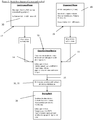
- the method 200 of production of microparticles 100 is an emulsion based/templated synthesis route.
- the emulsion based synthesis route described is an oil in water emulsion based synthesis route. However, it will be appreciated that a water in oil emulsion based synthesis route could also be used.
- the method 200 includes in a preparing step 201 preparing the first continuous phase 30 and the second dispersed phase 40 to the required specifications.
- the method further includes a first mixing or emulsifying step 210 and a second drying step 220.
- continuous phase 30 and dispersed phase 40 are provided via separate inlets 14 and 15 to the shear device 10.
- the emulsifying step 210 the continuous and dispersed phases are mixed to produce emulsion 50 of emulsion droplets 51.
- the control of the mixing and emulsifying step 210 controls the size and size distribution of emulsion droplets 51.
- Control of the mixing and emulsifying step 210 includes control of operation of the shear device including shear rate, flow rates of the continuous and dispersed phases into the device.
- the drying step 220 controls the morphology of microparticle 100. Control of the morphology is also provided by the selection of components of the continuous and dispersed phases.
- Other parameters of the method which may also be varied to control size and morphology of microparticles have been discussed above. In practice, a number of different parameters of the method are controlled and varied to control size and morphology of the microparticles, as required.
- the flow rates of the continuous phase 30 and dispersed phase 40 to the shear device 10 are controlled as required.
- the continuous phase 10 is provided to the shear device 2 in a preferred exemplary arrangement at a flow rate of up to 4mL/minute.
- the dispersed phase 20 is provided to the shear device 2 in a preferred exemplary arrangement at a flow rate of up to 2 mL/minute.
- the dispersed phase 40 volume fraction is controlled during the emulsifying step 210 by the use of the separate ports 14 and 15 for the continuous and dispersed phases 30 and 40. Control of the flow rate of the two phases 30 and 40 provides for control of the viscosity ratio between the phases.
- the provision of two separate inlet ports as described allows for the dispersed phase to be provided into the continuous phase in the shear device.
- Other parameters which may be varied in the emulsifying step 210 include the shear rates of the continuous phase 30 and the dispersed phase 40. Further the diffusion rate of the continuous and the dispersed phases 30, 40 may be controlled to tune the microparticle 100 morphology. Further the diffusion rate of the dispersed phase solvent in the continuous phase 30, 40 may be controlled to tune the microparticle 100 morphology.
- the emulsification step 210 controls the droplet (and therefore microparticle 100) size and size distribution, and the drying step 220 determines the microparticle morphology.
- the factors affecting the step 220 of drying the droplet 51 and associated particle aggregation include, the following:
- One or more of the above parameters may be adjusted or varied, as required.
- the drying step 220 By controlling and varying parameters of the drying step 220 it is possible to control morphology of the microparticles 100. In particular by controlling the drying of the emulsion 50 it is possible to control the morphology and therefore the surface area and volume ratios of the microparticles 100.
- the mixing speed In the drying step 220, it is possible to control the mixing speed by controlling and varying the speed of operation of the impellor 23. The mixing speed is varied up to 400 RPM. The temperature is controlled as required. The temperature is varied between 5 and 80 degrees Celsius as required. The dispersed phase vapour pressure is controlled and varied as required.
- parameters of the method 200 e.g. nanoparticle concentration in dispersed phase are set prior to the emulsion droplets 51 entering the drying bath 20.
- parameters such as temperature, degree of mixing, and head space vapour pressure are properties of the drying bath 20, and are controllable in the drying step 220 to achieve the desired drying rate and microparticle 100 morphology. Therefore, the use of an enclosed drying bath 20 with precise control over these parameters is required subsequent to the emulsification step 210.
- FIG. 7 there is provided an illustration of drying to form microparticles of different morphology.
- the drying step 220 provides greater control of microparticle 100 morphology than for example prior spray drying techniques.
- Microparticles 100 are provided according to the present specification.
- the system 1 and method 200 provide for the production of microparticles 100 with a high level of control of the microparticle morphology and properties.
- Microparticles 100 of a production run of method 200 have high levels of uniformity of microparticle size and morphology.
- Other properties of microparticles 100 include particles have a high surface area per unit volume.
- Microparticles 100 having different morphologies have been produced including crumpled and dimpled microparticles and porous microparticles 100.
- Microparticles 100 may comprise superparamagnetic microparticles.
- Superparamagnetic microparticles 100 have a high magnetic separation velocity.
- Microparticles 100 may be polymer coated if required.
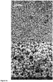
- FIGs. 9A-C SEM images of superparamagnetic microparticles 100 produced with ferrofluid nanoparticle concentrations of 1 mg/ml, 0.5mg/ml and 0.1mg/ml respectively are shown showing the transition from spherical to dimpled and crumpled particles with decreasing nanoparticle concentration.
- the hollow area inside the dimpled and crumpled microparticles 100 indicate that a nanoparticle shell developed at the surface of the emulsion droplet during drying which then collapsed inward as drying continued.
- the hollow nature of the dimpled and crumpled particles indicates that the particles were formed through a shell formation and buckling mechanism.
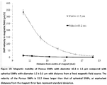
- crumpled microparticles 100 are shown to have a magnetic separation velocity substantially six times lower than spherical particles (SMPs) of equivalent diameter. Dimpled particles were shown to have a velocity substantially 1.3 times lower than spherical SMPs. Further the crumpled microparticles were found to have a surface area per unit volume substantially seven times higher than that of spherical particles of similar diameter. Referring to Fig. 11 it is shown that crumpled microparticles 100 have a binding capacity per unit volume substantially seven times higher than for example spherical particles of equivalent diameter.
- SMPs spherical particles
- Dynal 1 ⁇ m beads have a magnetic separation velocity 6 times lower than internally produced spherical particles 1 ⁇ m in diameter.
- the magnetic separation velocity of the 1 ⁇ m crumpled particles according to the present specification is equivalent to the separation velocity of spherical 1 ⁇ m Dynal beads from Invitrogen,while the surface area per unit volume is substantially 6 -7 times higher.
- a shell during droplet drying may be explained by an increased affinity of the iron oxide nanoparticles for the oil-water interface.
- Oleic acid chains bound to the nanoparticles make them oil- soluble and also act as a stabilizer to prevent undesired aggregation.
- Incomplete coverage of the nanoparticles with oleic acid may result in a reduction of their hydrophobicity and, correspondingly, an increased affinity for the oil-water interface, leading to their accumulation and locking at the surface of the droplet.
- the density of oleic acid side chains on the iron oxide nanoparticles was measured for the stock ferrofluid (the resulting microparticles are shown in Figure 9 ) and after washing with ethanol.
- a close-packed monolayer of oleic acid on a flat surface corresponds to ⁇ 4.17 chains/nm
- the stock nanoparticles (5.48 chains/nm2) therefore have a monolayer of adsorbed oleic acid, with the density higher than the close-packed value attributable to the curvature of the nanoparticles.
- the chain density is depleted to 2.31 chains/nm2 after two ethanol washing steps, which corresponds to a submonolayer coverage of ⁇ 42% on the nanoparticles.
- the contact angle of the nanoparticles changes after washing so that they have a greater affinity for the oil-water interface and also a greater tendency to aggregate with each other.
- nanoparticles could no longer be fully redissolved in hexane due to the decrease in their hydrophobicity.
- SMPs were synthesized with nanoparticles that were washed twice with ethanol.
- micro- particles produced with 1 g/L ethanol-washed nanoparticles are mostly crumpled ( Figure 14A ).
- SMPs produced using the unwashed nanoparticles with a monolayer of oleic acid and at the same nanoparticle concentration (1 g/L) are spherical ( Figure 9A ) . Therefore, when the nanoparticle concentration is kept constant, the nanoparticle chain density influences the drying route to that of either spherical or crumpled microparticles. This indicates that the nanoparticle chain density determines their affinity for the interface and aggregation to each other and thus the likelihood of the formation of a shell of nanoparticles at the interface.
- nanoparticle concentration influences the resulting microparticles
- SMPs were synthesized with 5 g/L ethanol-washed nanoparticles (i.e., submonolayer oleic acid coverage).
- the SMPs were found to be dimpled ( Figure 14B ), suggesting that nanoparticle concentration, independently of nanoparticle oleic acid coverage, influences the drying route and resulting microparticle morphology. From these results it can be inferred that the microparticle morphology depends on two factors: (i) the density of oleic acid chains attached to the nanoparticles and (ii) the concentration of iron oxide nanoparticles in the ferrofluid.
- the oleic acid chain density on the nanoparticles affects the rate of nanoparticle aggregation events and therefore the number of seed nuclei.
- the nuclei are drawn to the energy well at the oil-water interface due to amphiphilic nature of the oleic acid-deficient nanoparticles.
- the concentration of nanoparticles then may determine the growth rate of the seed nuclei and, by mass balance, the thickness of the shell of densely packed nanoparticles that forms at the droplet interface.
- E the Young's modulus
- r the shell radius
- ⁇ the Poisson ratio
- t the shell thickness.
- the thicker shells that form at higher nanoparticle concentrations are stronger and more resistant to buckling, and therefore likely to collapse inward at only one location, unlike the thinner shells that form at low nanoparticle concentrations and buckle at multiple locations as drying proceeds. In this way, dimpled and crumpled microparticles form at higher and lower nanoparticle concentrations, respectively.
- buckling of the shell may also be hindered due to spatial constraints within the droplet at higher nanoparticle concentrations.
- diluting the stock to the desired nanoparticle concentration with hexane also decreases the free oleic acid concentration, which in turn resulted in the detachment of oleic acid from the nanoparticles to maintain the equilibrium between bound and free oleic acid moieties (the solubility of oleic acid in hexane is assumed to be similar to that of stearic acid, i.e., ⁇ 16 g/L38).
- the density of oleic acid chains on the nanoparticle surface decreases when the stock ferrofluid is diluted. Diluting the stock therefore had the combined effect of reducing both the nanoparticle oleic acid density and the nanoparticle concentration in the dispersed phase, both of which lead to shell formation and subsequent buckling during drying to form dimpled and crumpled SMPs.
- Microparticles formed by a method and system according to the present specification are typically in the size range to 100 nm to 20 microns.
- Exemplary methods describing production of microparticles 100 according to the present specification and the method 200 are described as follows. The exemplary methods are intended to assist in the understanding of the invention and are not intended to be limiting.
- Example 1 relates to the general synthesis route up to the point where the bare unfunctionalized particles
- Examples 2 - 9 relate to synthesis of microparticles of the different morphologies described
- Examples 10 - 11 cover the particle functionalisation and their applications.
- Example 12 relates to magnetic mobility measurement.
- a magnet was placed next to the beaker to collect the black precipitate, which was washed three times with ethanol 200ml, after each wash a magnet was placed next to the beaker and the ethanol solution poured to waste. This process was repeated with DI water 200ml three times followed by 20% perchloric acid 200ml three times, DI water 200ml three times and finally ethanol 200ml three times. After the last ethanol wash the solution was poured away and hexanes 400ml was added to the beaker. The black precipitate (iron oxide nanoparticles) was easily dispersed in hexane resulting in a nonaqueous ferrofluid.
- stock ferrofluid (5 mL, 90 mg/mL) may be mixed with ethanol (35 mL) in a 50 mL centrifuge tube.
- the nanoparticles were dispersed in the mixture by sonication and vigorous mixing.
- the mixture was then centrifuged at 4000 rpm in a Rotina 420R centrifuge (Hettich, Tuttlingen, Germany).
- the supernatant was decanted, and a fraction of the sediment (ca. 100 mg) was removed and dissolved in hexane-this ferrofluid was washed once.
- the remainder of the sediment was resuspended in ethanol (40 mL) and centrifuged as before. This procedure was repeated 3 ⁇ , after which the iron oxide nanoparticles could not be fully redissolved in hexane.
- a continuous phase consisting of a thickener such as Dextran (Mw 50 - 650 kDa) 5 - 30% w/w or Polyvinylpyrrolidone (1300 kDa) 5 - 30%, and containing a surfactant such as SDS, Triton X-100 or Tween 20 at 0.1 - 20 % w/w 50 mL, and hexane 50 mL containing dissolved iron oxide nanoparticles at concentrations between 0.1 and 200 mg/mL were pumped into the couette mixer at different inlet ports.
- the aqueous phase was pumped at a rate of 0.2 - 4 mL/min and the organic phase at a rate of 0.2 to 4 mL/min.
- the droplet size was adjusted through variation of the shear rate and the dispersed phase volume fraction (See Figs. 5A and 5B ).
- the homogenised emulsion was collected in a drying bath (500 - 5000 mL containing a surfactant such as SDS, Triton X-100, Tween etc.) under gentle agitation (150-170rpm) and the emulsion was left to dry for 24 hours.
- the collected microparticles were washed with 0.5% Triton-100 solution for 2 times to remove residual dextran.
- emulsion droplets were obtained using a Zeiss microscope with a 60x or 100x objective lens in Differential Imaging Contrast (DIC) mode.
- SEM Images of the microparticles were obtained using a Hitachi TM-1000 or FEI Quanta 30 FEG Dualbeam.
- Optical sizing software (Axiovison 4.8) was used to measure droplet and microparticle size distributions from the obtained images. More than 80 data points were used when measuring size distributions of superparamagnetic particles and emulsion droplets.
- Magnetic properties were performed on a Quantum Design Magnetic properties measurement system, MPMS, Superconducting Quantum Interference Device. Iron content was analysed using atomic adsorption.
- Dextran (50 - 150kDa) 10% w/w, SDS 4% w/w solution 20 mL and hexane 80 mL containing dissolved iron oxide nanoparticles at concentration 10 mg/mL were pumped into the couette mixer through separate inlet ports.
- the aqueous phase was pumped at a rate of 0.2 mL/min feeding speed and the organic phase at a rate of 0.8 mL/min.
- the rotor speed was adjusted to 600 rpm (13900 s -1 ).
- the homogenised emulsion was collected in a drying bath (850 mL at 0.5% Triton) under gentle agitation (150-170rpm) and the emulsion was left to dry for 24 hours.
- the microparticles that had settled after 24 hours were collected and washed with 0.5% Triton-100 solution for 2 times to remove residual dextran.
- Polyvinylpyrrolidone (1300 kDa) 15% w/w, SDS 4% w/w solution 20 mL and hexane 80 mL containing dissolved iron oxide nanoparticles at concentration 10 mg/mL were pumped into the couette mixer through separate inlet ports.
- the aqueous phase was pumped at a rate of 0.2 mL/min feeding speed and the organic phase at a rate of 0.8 mL/min.
- the rotor speed was adjusted to 300 rpm (6950 s -1 )
- the homogenised emulsion was collected in a drying bath (850 mL at 0.5% Triton) under gentle agitation (150-170rpm) and the emulsion was left to dry for 24 hours. Using a magnet the microparticles were collected on the bottom for 2 h and washed with 0.5% Triton-100 solution for 2 times to remove residual dextran.
- Dextran (50 - 150kDa) 5 - 10% w/w, SDS 0.5 - 4% w/w solution 50 mL and hexane 50 mL containing dissolved iron oxide nanoparticles at concentration 10 - 50 mg/mL were pumped into the couette mixer through separate inlet ports.
- the aqueous phase was pumped at a rate of 0.2 - 0.8 mL/min feeding speed and the organic phase at a rate of 0.2 - 0.8 mL/min.
- the rotor speed was adjusted to 100 - 800 rpm (2320 - 18540 s -1 )
- the homogenised emulsion was collected in a drying bath (850 mL at 0.5% Triton) under gentle agitation (150-170rpm) and the emulsion was left to dry for 24 hours.
- the microparticles that had settled after 24 hours were collected and washed with 0.5% Triton-100 solution for 2 times to remove residual dextran.
- microparticles were then carboxyl coated according to the procedure outlined in Example 7.
- 0.5 mg/mL microparticle suspensions 500 mL were centrifuged at 100 - 4000 rpm for 3 min, the speed dependant on the size of the microparticles to be isolated.
- the sediment microparticles were resuspended in DI water and sonicated for 1 min, and the process was then repeated until the desired size and uniformity of the microparticles was achieved.
- Dextran (50 - 150kDa) 25% w/w, SDS 2 - 4% w/w solution 30 mL and hexane 10 mL containing dissolved iron oxide nanoparticles at concentration 0.5 mg/mL were pumped into the couette mixer through separate inlet ports.
- the aqueous phase was pumped at a rate of 0.75 mL/min feeding speed and the organic phase at a rate of 0.25 mL/min.
- the rotor speed was adjusted to 50 - 300 rpm(1160 - 6950 s -1 )
- the homogenised emulsion was collected in a drying bath (850 mL at 0.5% Triton) under gentle agitation (150-170rpm) and the emulsion was left to dry for 24 hours.
- the microparticles that had settled after 24 hours were collected and washed with 0.5% Triton-100 solution for 2 times to remove residual dextran.
- Fig. 1 Referring to Fig. 1 a 25% w/w dextran 30 mL (Mw 75 kDa) was pumped into the couette mixer at a rate of 0.75 mL/min, and hexane 10 mL containing hydrophobized iron oxide nanoparticles 15 mg/ml and 5% w/w oleic acid (Fisher Scientific) was pumped into the mixer at a rate of 0.25 mL/min. The rotor speed was adjusted to between 100 to 200 RPM.
- the emulsion was transferred to an evaporation dish containing 800 ml water at 0.5% w/w Triton X-100 (Sigma Aldrich) under gentle agitation. After 24 hours the dried microspheres 500 were collected with a magnet and washed with 0.5% Triton X-100 solution to remove residual dextran.
- Fig. 1 Referring to Fig. 1 a 10% w/w dextran 30 mL (Mw 75 kDa) containing 2% w/w SDS was pumped into the couette mixer at a rate of between 0.75 to 0.9 mL/min, and hexane 10 mL containing hydrophobized iron oxide nanoparticles 80 mg/mL was pumped into the mixer at a rate of between 0.25 to 0.1 mL/min. The total flowrate of the dispersed and continuous phases was 1 mL/min. The rotor speed was adjusted to between 100 to 200 RPM.
- the emulsion was transferred to an evaporation dish and allowed to dry under no agitation. After 24 hours the dried microspheres 500 were collected with a magnet and washed with 0.5% Triton X-100 solution to remove residual dextran.
- Fig. 1 Referring to Fig. 1 a 10% w/w dextran 30 mL (Mw 75 kDa) containing between 0.1 and 0.5% w/w SDS was pumped into the couette mixer at a rate of between 1 and 3 mL/min, and hexane 10 mL containing hydrophobized iron oxide nanoparticles 15 mg/mL was pumped into the mixer at a rate of between 0.25 to 1 mL/min. The rotor speed was adjusted to between 100 to 200 RPM.
- the emulsion was transferred to an evaporation dish containing 800 ml water at 0.5% w/w Triton X-100 (Sigma Aldrich) under gentle agitation. After 24 hours the dried microspheres 500 were collected with a magnet and washed with 0.5% Triton X-100 solution to remove residual dextran.
- Fig. 1 Referring to Fig. 1 a 10% w/w dextran 30 mL (Mw 75 kDa) containing between 0.1 and 0.5% w/w SDS was pumped into the couette mixer at a rate of between 0.75 and 3 mL/min, and hexane 10 mL containing hydrophobized iron oxide nanoparticles 80 mg/mL was pumped into the mixer at a rate of between 0.25 to 1 mL/min. The rotor speed was adjusted to between 100 to 200 RPM.
- the emulsion was transferred to an evaporation dish containing 800 ml water at 0.5% w/w Triton X-100 under gentle agitation. After 24 hours the dried microspheres 500 were collected with a magnet and washed with 0.5% Triton X-100 solution to remove residual dextran.
- Microparticles may be functionalised as required for different applications.
- an exemplary method described to assist in understanding the present method and properties of microparticles produced by the method The examples are not intended as limiting.
- Example 10 Polymer coating and Avidin functionalisation of microparticles and binding capacity of biotin-HRP measurement
- Dried microparticles were resuspended in a solution of 0.05% (w/w) Triton X-100, 250 mM NaCl, and 4.5% (w/w) PEI (50 mL total).
- the microparticle suspension was gently mixed, sonicated for 2 min and incubated at RT for 16 h.
- the microparticles were washed 3 ⁇ with 250 mM NaCl 25 mL with 30 s sonication steps between each wash.
- the suspension was mixed, sonicated for 2 min, and incubated at RT for 6 h.
- the carboxylated microparticles were then washed 3 ⁇ with and resuspended in DI water.
- Microparticles 1 mg were suspended in a solution of Ethanol 1 mL, De-Ionized water 100 ⁇ L, Tetraethylorthosilicate (TEOS) 50 ⁇ L and mixed on rotating wheel at RT for 15 mins. Ammonium hydroxide (NH 3 OH) 20 ⁇ L was added and the solution was mixed on the rotating wheel at RT for 6 hours. The microparticles were sonicated at 1 hour intervals. The silica coated microparticles were collected with a magnet and washed 3 times with De-Ionized water.
- TEOS Tetraethylorthosilicate
- Silica coated microparticles 1 mg was suspended in Guanidine Hydrochloride 1 ml containing Salmon Sperm DNA 400 ⁇ g/mL. The suspension was incubated on a rotating wheel at RT for 10 hours. The microparticles were removed using a magnet, the concentration of DNA remaining was measured using a UV-Vis spectrophotometer, and the change in the DNA concentration from the start to the end was calculated.
- the magnetic mobility of microparticles was measured by applying magnetic forces on particles immersed in a viscous fluid, as reported in our previous work.
- a magnetic field was imposed by two pairs of NdFeB magnets (12.7 ⁇ 12.7 ⁇ 6.35 mm per pair; Apex Magnets, Orlando, WV) with the same poles facing each other over a 1 mm air gap.
- An aluminum magnet holder attached to a micromanipulator (Eppendorf, Hamburg, Germany) was used to position the magnets at specified distances from the imaging field of an inverted microscope (Zeiss). 20 ⁇ L of magnetic microparticle suspension, containing ca.
- a magnet was placed next to the beaker to collect the black precipitate, which was washed three times with ethanol (200ml), after each wash a magnet was placed next to the beaker and the ethanol solution poured to waste. This process was repeated with DI water (200ml) three times followed by 20% perchloric acid (200ml) three times, DI water (200ml) three times and finally ethanol (200ml) three times. After the last ethanol wash the solution was poured away and hexanes (400ml was added to the beaker. The black precipitate (iron oxide nanoparticles) was easily dispersed in hexane resulting in a nonaqueous ferrofluid.
- Dextran (Affymetrix Mw 60,000 - 90,000)25% w / w, SDS 2% w / w solution 60 mL and hexane 20 mL containing dissolved iron oxide nanoparticles are pumped into the couette mixer at different inlet ports.
- the aqueous phase is pumped at a rate of 0.75 mL / min feeding speed and the organic phase at a rate of 0.25 mL / min.
- the droplet size was adjusted through variation of the shear rate.
- the homogenised emulsion was collected in a drying bath (850 mL at 0.5% Triton) under gentle agitation (150-170rpm) and the emulsion was left to dry for 24 hours. Using a magnet the microparticles were collected on the bottom for 2 h and removed the upper solution. The collected microparticles were washed with 0.5% Triton-100 solution for 2 times to remove residual dextran.
- emulsion droplets were obtained using a Zeiss microscope with a 60x or 100x objective lens in Differential Imaging Contrast (DIC) mode.
- SEM Images of the microparticles were obtained using a Hitachi Z-4300 with an accelerating voltage of 15 kV.
- Optical sizing software (Axiovison 4.8) was used to measure droplet and microparticle size distributions from the obtained images. More than 80 data points were used when measuring size distributions of superparamagnetic particles and emulsion droplets.
- Microparticles were produced using the ESE method described above, varying the concentration of iron oxide nanoparticles in the hexane phase between 0.1 and 1 mg / ml.
- the morphology of the microparticles can be seen in Fig. 6 , nanoparticle concentrations above at or above 1 mg / ml the microparticles were smooth and spherical, at 0.5 mg / ml the microparticles were dimpled and at 0.1 mg / ml the microparticles had a crumpled morphology.
- TEM images of cross-sections of the microparticles are shown in Fig. 7 .
- the hollow nature of the dimpled and crumpled particles indicates that the particles were formed through a shell formation and buckling mechanism.
- the surface area to mass ratio of the microparticles is higher for dimpled and crumpled particles than for spherical particles.
- a colorimetric assay was performed where the biotin-HRP binding capacity per milligram was measured for each of the different microparticle morphologies after streptavidin functionalisation. As shown in Fig. 9 , higher binding capacities per milligram of the dimpled and crumpled microparticles demonstrate larger surface area to mass ratio than spherical microparticles.
- the velocity of the different types of microparticles in a magnetic field was also investigated.
- the largest diameter (measured as maximum diameter) particles (1.2 ⁇ m approx) were isolated through centrifugation for each morphology, and suspended in a well at a varying distance from a bar magnet.
- the velocities of the different types of microparticles with distance from the bar magnet is shown in Fig. 8 .
- the surface area of superparamagnetic microparticles can be increased by decreasing the diameter of the microparticles, however this also drastically reduces the velocity of the microparticles in a magnetic field.
- novel dimpled and crumpled particle morphologies introduced here have a higher surface area to mass ratio than similar sized spherical microparticles, while maintaining large magnetic field velocities due to their large size and solely magnetite composition, making them more suitable for large scale magnetic separation processes where high microparticle surface area and magnetic field velocity are desirable.
- the method 200 of the present specification provides that the particle morphology can be tuned by controlling parameters including the drying conditions.
- the morphology of the microparticles 100 can be tuned to be dimpled or crumpled dramatically increasing the surface area to volume ratio of the micron sized particles, while maintaining a high magnetic moment due to the absence of polymer.
- the microparticles 100 show higher magnetisation due to the absence of polymer, have higher surface area than conventional spherical microparticles and, advantageously can be produced without using more complex double emulsion or templating and etching processes.
- the method can also be used to provide porous or hollow microparticles.
- microparticles 100 of different morphologies have been provided included crumpled and dimpled microspheres.
- the crumpled and dimpled microparticles have an advantageous configuration over similar sized spherical microparticles for applications in affinity separations, targeted drug delivery, diagnostics due to their high surface area and magnetic mobility.
- the microparticles may be superparamagnetic microparticles comprised of superparamagnetic nanoparticles.
- the microparticles may also comprise other material for example polymer, fluorescent material or an encapsulated drug.
- microparticles may also be provided according to the method and system as described.
- the crumpled and dimpled microparticles have surface area to volume ratio.
- the microparticles 100 comprised of superparamagnetic nanoparticles have a high binding capacity and magnetic mobility or separation velocity.
- Microparticles comprising self-assembled iron-oxide microparticles demonstrate a higher magnetic moment than either the individual nanoparticles or polymer/magnetite composites.
- the present specification further provides a method 400 for producing superparamagnetic microspheres 500 which are produced using an emulsion solvent evaporation (ESE) method 400.
- ESE emulsion solvent evaporation
- the preparation of single emulsions consists of two steps; the first step involves the emulsification of the polymer or nanoparticle suspension in a second immiscible phase, with surfactant used to stabilise the droplets, and the second step involves the evaporation of the solvent and the accompanying crystallisation/precipitation of the polymer or nanoparticles.
- the preparation of double emulsions is similar to that of single emulsions, but with a second emulsification step where the primary emulsion is emulsified in a third phase.
- Porous and hollow superparamagnetic microspheres 500 in the size range of 3-10 microns are produced by the ESE method 400.
- the formation of double W/O/W emulsions and subsequent hardening of the dissolved material provides for the hollowness and porosity of the microspheres.
- the methods of preparation of the hollow ( Fig. 16 ) and the porous ( Fig. 17 ) microspheres differ slightly in the types and concentrations of surfactants used to stabilise the emulsions and the concentrations of iron oxide nanoparticles in the oil phase.
- Figs. 17 and 18 show examples of porous particles.
- a 20% w/w dextran 30 mL (Sigma Aldrich Mw 150,000) was pumped into the couette mixer at a rate of 0.75 mL/min, and 10 ml hexane containing 80 mg/ml hydrophobized iron oxide nanoparticles and 5% w/w oleic acid (Fisher Scientific) was pumped into the mixer at a rate of 0.25 mL/min.
- the rotor speed was adjusted to 150 RPM.
- the homogenised emulsion was transferred to an evaporation dish containing 800 ml water at 0.5% w/w Triton X-100 (Sigma Aldrich) under gentle agitation. After 24 hours the dried microspheres 500 were collected with a magnet and washed with 0.5% Triton X-100 solution to remove residual dextran
- the method includes
- Superparamagnetic microspheres have applications in affinity separations due to the speed, ease, efficiency and inexpensive nature of magnetic separation.
- the microspheres can be functionalized with receptors such as antibodies that are capable of binding to specific ligands on the target of interest such as cells, proteins and viruses in fermentation broths and culture media.
- a magnet can then be used to separate the microspheres together with the target of interest.
- the microparticles previous have been typically composed of iron oxide superparamagnetic nanoparticles for example distributed in a polymer microparticle matrix. Self-assembled iron-oxide microspheres consisting solely of iron oxide nanoparticles demonstrate a higher magnetic moment than either the individual nanoparticles or polymer/magnetite composite microparticles.
- porous superparamagnetic microspheres reported here does not require the incorporation of a gelatin or polymer template as the iron oxide nanoparticles self assemble upon drying. Therefore there are a lower number of steps (no templating and etching) in the microparticle production process and the iron oxide content and therefore magnetisation of the microspheres is higher, rendering them more mobile and easier to manipulate in a magnetic field, due the large magnetic mobility of the porous microparticles.
- the porous are advantageous from point of view of ease of manufacture, binding capacity and magnetic mobility.
- the desired hollow spheres are formed together with smaller denser microspheres and some fragments of large hollow microspheres.
- the droplet size distribution should be better controlled to solely produce the desired hollow microspheres.
- the porous microspheres can be developed reproducibly although the exact mechanism of their formation and their internal structure have not been fully characterised. Centrifugation is required to separate the largest size fraction of porous microparticles (10 - 15 ⁇ m).
- the surface area of the microspheres is significantly increased when compared to solid microspheres of equal size, while a high magnetic moment is maintained by using large microparticles (as opposed to nanoparticles) and not incorporating a polymer into the microsphere.
- the present specification further provides a method 400 for producing superparamagnetic microspheres 500 which are produced using an emulsion solvent evaporation (ESE) method 400.
- ESE emulsion solvent evaporation
- the preparation of single emulsions consists of two steps; the first step involves the emulsification of the polymer or nanoparticle suspension in a second immiscible phase, with surfactant used to stabilise the droplets, and the second step involves the evaporation of the solvent and the accompanying crystallisation/precipitation of the polymer or nanoparticles.
- the preparation of double emulsions is similar to that of single emulsions, but with a second emulsification step where the primary emulsion is emulsified in a third phase.
- Porous and hollow superparamagnetic microspheres 500 in the size range of 3-10 microns are produced by the ESE method 400.
- the formation of double W/O/W emulsions and subsequent hardening of the dissolved material provides for the hollowness and porosity of the microspheres.
- the methods of preparation of the hollow ( Fig. 9 ) and the porous ( Fig. 10 ) microspheres differ slightly in the types and concentrations of surfactants used to stabilise the emulsions and the concentrations of iron oxide nanoparticles in the oil phase.
- a mixture of 8 g dextran (Affymetrix Mw 60,000 - 90,000) and 0. 16 g sodium dodecyl sulfate (Sigma Aldrich) is dissolved in 24 ml deionised water and added to 10 ml hexane containing 100 mg/ml hydrophobized iron oxide nanoparticles in a 50 ml tube.
- An emulsion 450 is produced by gently mixing the phases on a rotating wheel for 30 minutes.
- the premixed emulsion 450 (40 ml is then homogenised in a couette type shear mixer 460, being pumped through at a rate of 1 ml/ min with a rotor speed of 175 RPM (residence time approx 30 s) .
- the homogenised emulsion is transferred to an evaporation dish containing 800 ml water at 0.5% w/w Triton X-100 (Sigma Aldrich) under gentle agitation. After 24 hours the dried microspheres 500 are collected with a magnet and washed with 0 .5% Triton X-100 solution to remove residual dextran
- a mixture of 8 g dextran (Affymetrix Mw 60,000 - 90, 000) is dissolved in 24 ml deionised water and added to 10 ml hexane containing 15 mg/ml hydrophobized iron oxide nanoparticles and 0.7g oleic acid (Sigma Aldrich) in a 50 ml tube.
- An emulsion is produced by vigorously hand mixing the emulsion for 1min followed by gently mixing the phases on a rotating wheel for 1 hour.
- the premixed emulsion (40 ml) is then homogenised in a couette type shear mixer, being pumped through at a rate of 1 ml/min with a rotor speed of 200 RPM (residence time approx 30 s).
- the homogenised emulsion was then transferred to an evaporation dish containing 800 ml water at 0 .5% w/w Triton x-100 (Sigma Aldrich), under gentle agitation. After 24 hours the dried microspheres were collected with a magnet, washed with 0.5% Triton x-100 solution to remove residual dextran.
- Superparamagnetic microspheres have applications in affinity separations due to the speed, ease, efficiency and inexpensive nature of magnetic separation.
- the microspheres can be coated with receptors such as antibodies that are capable of binding to specific ligands on the target of interest such as cells, proteins and viruses in fermentation broths and culture media.
- a magnet can then be used to separate the microspheres together with the target of interest.
- microparticles previous have been typically composed of iron oxide superparamagnetic nanoparticles for example distributed in a polymer microparticle matrix.
- Self-assembled iron-oxide microspheres consisting solely of iron oxide nanoparticles demonstrate a higher magnetic moment than either the individual nanoparticles or polymer/magnetite composite microparticles.
- the method 400 provides a way to increase the surface area of microparticles 500 while maintaining high magnetic moment by using porous or hollow microparticles.
- a straight -forward approach is to use higher concentrations of spherical microspheres to achieve the higher surface area required without changing the surface area to volume ratio of the microparticles.
- Porous superparamagnetic Gd20O 3 200 nm have been previously developed, where the Gd20 O 3 was deposited on a gelatine core or in an organic gelatin matrix which was subsequently removed using calcination resulting in hollow and porous spheres. Similar methods reported also require etching of a template core to obtain the necessary porous structure.
- a double emulsion ESE (as used here) method has also been used to produce hollow polymeric microspheres with magnetite embedded in a polystyrene matrix.
- the method of preparation of the hollow and porous superparamagnetic microspheres reported here does not require the incorporation of a gelatin or polymer template as the iron oxide nanoparticles self assemble upon drying. Therefore there are a lower number of steps (no templating and etching) in the microsphere production process and the iron oxide content and magnetisation of the microspheres is higher, rendering them more mobile and easier to manipulate in a magnetic field.
- hollow microspheres form above a certain threshold size below which dense homogeneous microspheres form. At droplet sizes well above this threshold the formed hollow microspheres are structurally unstable and break apart. As the current couette mixer of homogenisation produces a range of droplet sizes, the desired hollow spheres are formed together with smaller denser microspheres and some fragments of large hollow microspheres. The droplet size distribution should be better controlled to solely produce the desired hollow microspheres.
- the porous microspheres can be developed reproducibly although the exact mechanism of their formation and their internal structure have not been fully characterised. In both cases the available surface area and velocity in a magnetic field have not been characterised.
- the surface area of the microspheres is significantly increased when compared to solid microspheres of equal size, while a high magnetic moment is maintained by using large microparticles (as opposed to nanoparticles) and not incorporating a polymer into the microsphere.
- the system 1 and method 200 of the present specification enables the high throughput production of emulsions and precise control over emulsification and drying steps to reproducibly synthesise uniformly sized particles with the required morphology on a large scale.
- the specification further provides shear device 10.
- the use of separate inlet ports according to the shear device 10 of the system 1 of the present specification addresses the problems mentioned in connection with previous methods for example, when separate inlets are used for the different phases, emulsification occurs within the shear device, and therefore no premixing is required.
- Phase separation of the premix is no longer an issue with the separate inlet setup. Therefore the system can be scaled up and the production time is limited only by the capacity of the individual continuous and dispersed phase reservoirs, in comparison with previous methods where there were problems associated with premix phase separation limiting the batch size.
- the use of separate ports for the dispersed and continuous phases allows the dispersed phase volume fraction to be precisely controlled over the entire course of production, resulting in precise control over droplet size and size distribution.
- the use of separate ports enabling scale up of emulsion / superparamagnetic particle synthesis, is advantageous over approaches that have been used previously.
- the provision of a scalable method is advantageous for the production of microparticles on a commercial scale providing for increased reliability of the method and decreased costs.
- the system and method of the present specification allow large scale synthesis of uniform emulsions or the large scale emulsion templated synthesis of uniform polymeric microspheres.
- Superparamagnetic microparticles have applications in targeted drug delivery, diagnosis, and are widely used in affinity separations due to the speed, ease, efficiency and inexpensive nature of magnetic separation.
- the microparticles are typically composed of iron oxide superparamagnetic nanoparticles either distributed in a polymer microparticles matrix, or self-assembled to form a tightly packed superparamagnetic microparticle.
- Self-assembled iron-oxide microparticles demonstrate a higher magnetic moment than either the individual nanoparticles or polymer/magnetite composites.
- Emulsion templated self-assembly of superparamagnetic nanoparticles may be used to produce for example, spherical superparamagnetic microspheres.
- Superparamagnetic microparticles are extensively used in the purification of biomolecules due to the speed and ease of magnetic separation. It is desirable that the microparticles used in biological affinity separations have both high surface area and high magnetic mobility to facilitate a high binding capacity of target biomolecules and their rapid removal from solution, respectively. Scaling laws for conventional spherical superparamagnetic microparticles are such that increasing the microparticle specific surface area results in a significant decrease in the magnetic mobility. More favorable combinations of these key parameters can be found if alternative microparticle morphologies are developed for use in affinity separations.
- Emulsion-templated self-assembly of iron oxide nanoparticles into microparticle using oil-in-water emulsions was carried out using a modified Couette shear mixer as described with separate inlet ports for the oil and aqueous phases, enabling high throughput microparticle synthesis.
- the resulting microparticles were tuned to spherical, dimpled, or crumpled morphologies.
- the specific binding capacity and magnetic mobility of each type of microparticle were measured by a peroxidase-based colorimetric assay and by their magnetic field-induced motion in a viscous fluid, respectively.
- Superparamagnetic microparticles with dimpled and crumpled morphologies were found to have higher specific binding capacities compared to spherical microparticles, while maintaining high magnetic field velocities due to their high iron oxide content. Superparamagnetic microparticles with these novel morphologies would make excellent tools for affinity-based bioseparations where binding capacity and magnetic mobility are key factors.
- SMPs used in biological affinity separations have both high surface area and high magnetic mobility.
- the large surface areas provide, when functionalized with the appropriate ligands, a higher binding capacity, and therefore a lower mass of SMPs is required to achieve high analyte recovery.
- High magnetic mobilities enable fast separation of SMPs and reduce the time required to separate the beads from the supernatant after binding occurs.
- nanoparticles were deposited on a gelatine core or in an organic gelatin matrix which was subsequently removed using calcination resulting in hollow and porous spheres.
- etching of a template core was required to obtain the necessary porous structure.
- double emulsions have also been used to produce polymeric microspheres with magnetite embedded in a polystyrene matrix.
- the crumpled microparticles have a magnetic mobility 6 times lower than spherical particles, but a binding capacity 6-7 times higher.
- the method of the present specification are simplified.
- previous methods there is often an extra processing step in the form of removing the original template onto which the polymer-magnetite was deposited.
- the direct emulsion method of the present specification does not require the use of a template, an etching step, or the incorporation of a polymer.
- particles generated using the methods of the present specification have advantages in comparison with particles produced using the aforementioned prior techniques such as for example microparticles having magnetite embedded in a polymer matrix.
- the incorporation of the non-magnetic polymer reduces the magnetic moment and therefore magnetic separation velocity of these particles
- the method and system provide for large scale particle production. Microparticles may be produced in batches.
- input was provided via a single channel. Here, the inputs are provided in a continuous stream
- the emulsion templated self assembly method of the present specification an improved method for production of microparticles.
- the method provides for production microparticles of various size and morphology, as required.
- the method provides for production of a batch of particles of reduced size distribution/uniform particle size and accordingly improved % CV in comparison with the previous methods.
- the method provides for production of microparticles of different morphologies including spherical, crumpled, dimpled, porous and hollow, as required.
- the method includes a relatively small number of steps including the following: preparing an emulsion of an organic solvent containing dispersed metal oxide nanoparticles, for example, iron oxide nanoparticles at the selected concentration in an aqueous continuous phase, and then allowed to dry.
- the present method does not require the use of a pre-mixed emulsion being provided to a shear device for emulsification. Rather the separate phases are provided to the shear device. There is no premixing of the emulsion required and accordingly phase separation of the premixed emulsion does not occur and is not an issue.
- Throughput of the system of the present specification and the method of production of the present specification is accordingly limited not by factors such as separation of the pre-mixed emulsion. Therefore it is possible for the system of the present specification to be scaled up.
- the production time is limited only by the capacity of the individual continuous and dispersed phase reservoirs. While spray drying may be used to dry particles, it is noted that the time-scales of microparticle formation differ greatly between spray drying and emulsion driven nanoparticle self-assembly.
- the Couette shear device 10 having a cylindrical rotor and stator type arrangement is different to prior art devices, which may for example include flat plate or impellor or impellor and screen mesh device.
- the shearing force applied to the emulsion and droplets is uniform throughout the Couette shear device 10 and is controllable including by control of rotation speed of the rotor.
- the shearing force depends on the rotation speed of the mixer and the radial distance from the centre of the plate i.e. it is not constant in the flat plate device for a particular rotation speed.
- the final droplet size is proportional to the shearing force, it is desirable to have this force uniform, as in our setup.
- the arrangement of the device of the invention provides improved uniformity and control of the shearing force.
- the method of the specification provides for example for use of either nanoparticles alone dissolved in an organic solvent or a nanoparticle-polymer mixture. There is no further step for example incorporation of nanoparticles in a polymer melt in an organic solvent for the dispersed phase.
- the method provides that, superparamagnetic nanoparticles may comprise substantially 100% of the microparticle, conferring high magnetic mobilities to the microparticles.
- Microparticle morphology may be tailored by the method provided to give high surface area to volume ratios.
- the method provided has a low coefficient of variance without the further step of for example centrifugation.
- the method and system may be adapted flexibly to enable production of microparticles of controlled size, morphology/surface area and tuneable magnetisation, as required.
- control of morphology and surface area it is possible to provide a microparticle of relatively high binding capacity relative to similar sized (similar radius) particles of the prior art.
- control of magnetisation it is possible to provide microparticles of relatively high magnetic mobility in comparison with similar sized microparticles of the prior art.
- the method and system further advantageously provide for improved particle size distribution or more uniform particle size distribution.
- the method is therefore of improved efficiency and there is reduced waste and loss.
- the method and system may be used to produce microparticles of uniform size and monodispersity.
- Particles produced by the method and system may have CV ratio preferably of the order of ⁇ 25%.
- the method and system of the present specification advantageously provides a relatively simplified method for production of microparticles. Further the method of production of microparticles is highly reproducible.
- the gap size may be controlled to provide the required results.
- the gap size is preferably of the order of 100mn.
- the system also provides for high control of the speed of rotation.
- the system also provides for relative high speeds of rotation.
- microparticles of different sizes may be used preferentially for different particular applications.
- Microparticles of different magnetic mobility may be preferred for different applications.
- Microparticles of different binding capacity may be preferred for different applications.
- the method and system provide the ability to produce a batch of particles of a particular size in the range of from substantially.
- magnetic particles may be provided according to the present specification having different magnetisation. Such would allow for multiplex detection via MRI of different colours.
- different nanoparticles for example Iron nanoparticles such as Fe 2 O 3 and Fe 3 O 4 may be provided to produce tuneable magnetisation.
- the method provides tuneable magnetisation via selection of nanoparticles. Particles with tuneable magnetisation also have application for use in magnetophoresis.
- Functionalised superparamagnetic microparticles are often used in laboratory setting for the separation and purification of biomolecules such as nucleic acids and proteins.
- the present method does not require centrifugal separation. No centrifugal separation is required for example for spherical microparticles of the order of 350nm.
- Example 1 The crumpled particles described in Example 1 are comprised solely of iron oxide, advantageously resulting in higher mobility than for example, previous polymer-iron oxide composite particles.
- the parameters determining particle morphology are highly controllable and reproducible.
- the surface area / binding capacity of the different types of particles has been accurately measured times using a colorimetric biotin-HRP and -Avidin assay
- the method of preparation of the porous superparamagnetic microspheres of the present specification does not require the incorporation of a polymer as the iron oxide nanoparticles self-assemble upon drying.
- microparticles of controlled morphology and size, surface area and magnetisation may be used for different applications.
- Different microparticles may be used in different diverse applications including diagnostics where for example microparticles may be used to provide separation of an analyte automatically in a handheld strip diagnostic device.
- Microparticles suitable for large scale separations in the range of substantially 5-500 L may be provided.
- Large scale separation advantageously provides for a low cost and efficient separation.
- Constraints of the prior art addressed by the present application include time requirement or speed of the separation and magnetic field requirements.
- the method and the system of the invention advantageously provides for production of microparticles of relatively high surface area accordingly with increased binding capacity relative to similar sized particles of the prior art and further at the same time provide for particles of high magnetic mobility.
- Such particles may therefore be used for large scale separations of relative high speed without onerous requirements for magnetic field allowing a high throughput in separations for example of the order of 10k analytes per day.
Landscapes
- Chemical & Material Sciences (AREA)
- Engineering & Computer Science (AREA)
- Health & Medical Sciences (AREA)
- Organic Chemistry (AREA)
- Chemical Kinetics & Catalysis (AREA)
- Bioinformatics & Cheminformatics (AREA)
- Life Sciences & Earth Sciences (AREA)
- General Health & Medical Sciences (AREA)
- Nanotechnology (AREA)
- Dispersion Chemistry (AREA)
- Inorganic Chemistry (AREA)
- Epidemiology (AREA)
- Veterinary Medicine (AREA)
- Public Health (AREA)
- Animal Behavior & Ethology (AREA)
- Pharmacology & Pharmacy (AREA)
- Medicinal Chemistry (AREA)
- Molecular Biology (AREA)
- Biomedical Technology (AREA)
- Power Engineering (AREA)
- Colloid Chemistry (AREA)
- Medicinal Preparation (AREA)
- Physical Or Chemical Processes And Apparatus (AREA)
- Medicines Containing Antibodies Or Antigens For Use As Internal Diagnostic Agents (AREA)
- Manufacturing Of Micro-Capsules (AREA)
Claims (15)
- Verfahren (200) zum Herstellen von Mikropartikeln (100) unter Verwendung einer emulsionsbasierten Synthesemethode, das beinhaltet:(i) Bereitstellen einer ersten Fluidphase und einer zweiten Fluidphase, wobei die erste Fluidphase eine kontinuierliche Phase (30) ist und die zweite Fluidphase eine dispergierte Phase (40) ist, die ein dispergiertes Material (41) umfasst, wobei die kontinuierliche Phase mit der dispergierten Phase unvermischbar ist, wobei die kontinuierliche Phase ein Tensid umfasst;(ii) Bereitstellen einer Schervorrichtung (10) mit getrennten ersten und zweiten Einlässen für die erste kontinuierliche Phase und die zweite dispergierte Phase, wobei die Schervorrichtung einen Rotor aufweist, der so konfiguriert ist, dass er sich mit einer Drehzahl innerhalb eines ortsfesten Stators dreht, und eine ringförmige Lücke aufweist, die zwischen dem Rotor und dem Stator bereitgestellt ist, in der eine Emulgierung erfolgt, wobei die Schervorrichtung erste und zweite Einlassöffnungen umfasst, wobei die erste kontinuierliche Phase und die zweite dispergierte Phase der Schervorrichtung über getrennte Einlassöffnungen bereitgestellt werden;(iii) Mischen der ersten kontinuierlichen Phase und der zweiten kontinuierlichen Phase in Gegenwart des Tensids in der Schervorrichtung (10), um eine Emulsion (50) von Tropfen (51) zu bilden.,
wobei der Mischschritt einen Emulgierschritt umfasst, wobei die zweite dispergierte Phase in die erste kontinuierliche Fluidphase in der Schervorrichtung emulgiert wird, wobei ein Tropfendurchmesser und eine Varianz des Tropfendurchmessers steuerbar sind, um Mikropartikel mit einem gewünschten Durchmesser herzustellen, indem eines oder mehrere von (a) einer Größe der ringförmigen Lücke, die zwischen dem Rotor und dem Stator bereitgestellt ist, (b) einer Drehzahl des Rotors, (c) einer Volumenfraktion der dispergierten Phase, (d) einem Viskositätsverhältnis zwischen Phasen, (e) einer Viskosität der kontinuierlichen Phase; und (f) einer Tensidkonzenztration variiert wird;(iv) Steuern der Volumenfraktion der dispergierten Phase während des Mischschritts durch Steuern der Durchflussrate bei den getrennten Einlassöffnungen zu der Schervorrichtung für die kontinuierliche Phase und die dispergierte Phase;(v) Trocknen der Emulsion (50), die aus Tropfen (51) besteht, um Mikropartikel (100) zu bilden, wobei die Mikropartikel eines von einer kugelförmigen, knittrigen, gekräuselten, porösen oder hohlen Morphologie aufweisen und einen Varianzkoeffizienten des Mikropartikeldurchmessers von 25 % oder weniger aufweisen, und wobei eine Mikropartikeldurchmessergröße in dem Bereich von 1 Nanometer bis 1 Mikrometer, am meisten bevorzugt 200 Nanometern bis 1 Mikrometer, liegt. - Verfahren nach Anspruch 1, das ferner umfasst:- Steuern einer Mikropartikelmorphologie, um Mikropartikel mit einer kugelförmigen, knittrigen, gekräuselten, porösen oder hohlen Morphologie bereitzustellen.
- Verfahren nach Anspruch 1, wobei ein Tropfendurchmesser < 20 Mikrometer beträgt.
- Verfahren nach einem vorstehenden Anspruch, wobei das dispergierte Material Nanopartikel oder superparamagnetische Nanopartikel umfasst und wobei die Nanopartikel Metalloxidnanopartikel, am meisten bevorzugt Eisenoxidnanopartikel, z. B. Fe2O3 und/oder Fe3O4, sind.
- Verfahren nach Anspruch 4, wobei eine Magnetisierung von Mikropartikeln durch Steuern der Konzentration von Eisenoxid-Fe2O3- und/oder -Fe3O4-Nanopartikeln in der dispergierten Phase in dem Bereich von 0,1 bis 200 mg/ml gesteuert wird, wobei die Magnetisierung der Mikropartikel in dem Bereich von 20 bis 110 Am2/kg (20 bis 110 emu/g) steuerbar ist.
- Verfahren nach Anspruch 1, das das Steuern der Scherrate umfasst, wobei die Schervorrichtung mit Drehraten von bis zu 2000 U/min, vorzugsweise mit Raten zwischen 50 und 1000 oder 50 und 1500 U/min, je nach Bedarf, betrieben wird.
- Verfahren nach einem vorstehenden Anspruch, das das Steuern eines Viskositätsverhältnisses zwischen Phasen, die zu kontinuierlich dispergiert wurden, in dem Bereich zwischen 0,01 und 1 liegt, am meisten bevorzugt 0,1, umfasst.
- Verfahren nach einem vorstehenden Anspruch, wobei die Mikropartikel aus zumindest einem bestehen aus: superparamagnetischen Mikropartikeln, die durch Selbstassemblierung von superparamagnetischen Nanopartikeln mit Emulsionstemplate gebildet werden, oder die Mikropartikel umfassen aggregierte Nanopartikel.
- Verfahren nach einem vorstehenden Anspruch,
wobei die erste kontinuierliche Phase eine kontinuierliche wässrige oder Ölphase ist, die mit der zweiten dispergierten Phase unvermischbar ist, und
wobei Typ und Konzentration des Tensids nach Bedarf ausgewählt und gesteuert werden, um eine Partikelgröße zu steuern, und
wobei die Tensidkonzentration in dem Bereich von 0,1 bis 10 % gesteuert wird. - Verfahren nach einem vorstehenden Anspruch, wobei die erste kontinuierliche Phase ein Verdickungsmittel umfasst, wobei das Verdickungsmittel und eine Konzentration ausgewählt und gesteuert werden, um die Viskosität der kontinuierlichen Phase zu steuern.
- Verfahren nach einem vorstehenden Anspruch, wobei die dispergierte Phase ein organisches Lösungsmittel umfasst und wobei das dispergierte Material eines umfasst von:(i) Nanopartikeln;(ii) einer Nanopartikelsuspension.
- Verfahren nach einem vorstehenden Anspruch, wobei die dispergierte Phase ein organisches Lösungsmittel umfasst und wobei das dispergierte Material eines umfasst von:(i) einem Polymer;(ii) einer Polymerlösung, und wobei die Konzentration des dispergierten Materials in der dispergierten Phase variiert wird, um eine Mikropartikelgröße und -morphologie zu steuern.
- Verfahren nach Anspruch 11, wobei die Konzentration der dispergierten Nanopartikel in der dispergierten Phase vorzugsweise in dem Bereich von 0,1 bis 0,5 mg/ml liegt, um knittrige und gekräuselte Mikropartikel zu bilden, und wobei das dispergierte Material Eisenoxidnanopartikel umfasst und die Konzentration von Eisenoxidnanopartikeln in der dispergierten Phase auf zwischen 0,1 und 200 mg/ml variiert wurde, um die Mikropartikelmorphologie zu steuern.
- Verfahren nach einem vorstehenden Anspruch, das das Regeln einer Temperatur in der Schervorrichtung und in dem Trocknungsbad und das Auswählen eines Lösungsmittels der dispergierten Phase umfasst, um die Verdampfungsrate der dispergierten Phase zu steuern.
- Schervorrichtung (10) zum Mischen einer ersten Fluidphase und einer zweiten Fluidphase, die umfasst:
erste und zweite Einlassöffnungen (14, 15) für eine erste Fluidphase bzw. eine zweite Fluidphase, wobei die ersten und zweiten Einlassöffnungen für eine Verbindung mit Reservoirs (17, 18) kontinuierlicher und dispergierter Phasen konfiguriert sind,
einen Rotor (11), der so konfiguriert ist, dass er sich innerhalb eines ortsfesten Stators (12) dreht, wobei der Rotor und der Stator so angeordnet sind, dass eine Lücke (13) dazwischen bereitgestellt wird und so dass eine Emulgierung der dispergierten Phase in die kontinuierliche Phase in Gebrauch innerhalb der Schervorrichtung in der Lücke auftritt, während sich der Rotor dreht, um eine Emulsion zu bilden, die Emulsionstropfen umfasst,
wobei der Radius des Rotors und die Lückengröße zwischen dem Rotor und dem Stator optimiert werden, um eine Emulsionstropfengrößenverteilung zu minimieren, und
ferner umfassend ein Durchflussratensteuermittel zum Steuern der Durchflussrate der kontinuierlichen Phase und der Durchflussrate der dispergierten Phase in die Schervorrichtung und ein Schersteuermittel zum Steuern der Scherrate und/oder der Drehung des Rotors, und
Steuermittel zum Steuern der Volumenfraktion der dispergierten Phase durch Steuern der relativen Durchflussraten der ersten kontinuierlichen und zweiten dispergierten Phasen in die Schervorrichtung,
wobei die Lückengröße 100 Mikrometer beträgt und die Drehrate des Rotors in dem Bereich bis zu 2000 U/min steuerbar ist.
Applications Claiming Priority (2)
| Application Number | Priority Date | Filing Date | Title |
|---|---|---|---|
| GB1209681.4A GB2502577A (en) | 2012-05-31 | 2012-05-31 | Microparticles and a device and method for the production thereof |
| PCT/EP2013/061302 WO2013178802A2 (en) | 2012-05-31 | 2013-05-31 | Microparticles and a system and method for the synthesis of microparticles |
Publications (2)
| Publication Number | Publication Date |
|---|---|
| EP2854776A2 EP2854776A2 (de) | 2015-04-08 |
| EP2854776B1 true EP2854776B1 (de) | 2020-02-12 |
Family
ID=46582119
Family Applications (1)
| Application Number | Title | Priority Date | Filing Date |
|---|---|---|---|
| EP13726776.1A Active EP2854776B1 (de) | 2012-05-31 | 2013-05-31 | System und verfahren zur synthese von mikropartikeln |
Country Status (4)
| Country | Link |
|---|---|
| US (1) | US10005677B2 (de) |
| EP (1) | EP2854776B1 (de) |
| GB (1) | GB2502577A (de) |
| WO (1) | WO2013178802A2 (de) |
Families Citing this family (19)
| Publication number | Priority date | Publication date | Assignee | Title |
|---|---|---|---|---|
| EP2861760B1 (de) * | 2012-06-15 | 2020-01-01 | The Board of Regents of The University of Texas System | Sequenzierung von mehreren transkripten aus einer einzelnen zelle mit hohem durchsatz |
| US10293325B2 (en) | 2013-12-11 | 2019-05-21 | University Of Massachusetts | Core-shell multi-layer particles |
| US10513733B2 (en) | 2015-03-23 | 2019-12-24 | Board Of Regents, The University Of Texas System | High throughout sequencing of paired VH and VL transcripts from B cells secreting antigen-specific antibodies |
| WO2017199123A1 (en) | 2016-05-17 | 2017-11-23 | Ecole Polytechnique Federale De Lausanne (Epfl) | Device and methods for shell phase removal of core-shell capsules |
| JP2018019686A (ja) * | 2016-07-20 | 2018-02-08 | コニカミノルタ株式会社 | ゼラチン粒子、ゼラチン粒子の製造方法、ゼラチン粒子内包細胞、ゼラチン粒子内包細胞の製造方法、および細胞構造体 |
| CN111032134B (zh) * | 2017-06-30 | 2024-02-13 | 阿维塔斯有限公司 | 电喷雾导管 |
| WO2019084538A1 (en) | 2017-10-27 | 2019-05-02 | Board Of Regents, The University Of Texas System | TUMOR SPECIFIC ANTIBODIES, T CELL RECEPTORS AND METHODS OF IDENTIFICATION THEREOF |
| US11583924B2 (en) * | 2018-12-31 | 2023-02-21 | Tata Consultancy Services Limited | Synthesis of nano particles |
| CN109650974B (zh) * | 2019-01-14 | 2021-07-09 | 湖南大学 | 利用铁氧化物纳米材料降低堆肥过程中氮素损失并提高堆肥产品肥效的方法 |
| CN110164703B (zh) * | 2019-06-21 | 2021-07-09 | 江苏科技大学 | 多孔Fe3O4/C多面体材料及其制备方法和应用 |
| AU2020299588B2 (en) | 2019-07-01 | 2022-03-03 | Oakwood Laboratories, Llc | System and method for making microspheres and emulsions |
| CN111359551B (zh) * | 2020-03-24 | 2022-04-26 | 北京唯公医疗技术有限公司 | 磁性聚合物微球及其制备方法 |
| CN113024733B (zh) * | 2021-03-15 | 2022-04-01 | 华东理工大学 | 一种多孔材料的制备方法 |
| WO2023147368A2 (en) * | 2022-01-25 | 2023-08-03 | The Trustees Of The University Of Pennsylvania | Nanocrystal superparticles through a source-sink emulsion system |
| CN114534590B (zh) * | 2022-02-26 | 2023-06-09 | 四川大学 | 一种可控制备单分散双重乳液的旋转式套管微流控装置及方法 |
| CN115990441A (zh) * | 2022-10-21 | 2023-04-21 | 赛克赛斯生物科技股份有限公司 | 一种粒径均一聚乙烯醇栓塞微球制备系统及其制备方法 |
| WO2025101814A1 (en) * | 2023-11-07 | 2025-05-15 | Magnostics Limited | Uniform multi-layer silica coated porous/mesoporus magnetic beads, methods of making and uses thereof |
| CN118479950A (zh) * | 2024-05-17 | 2024-08-13 | 南京理工大学 | 基于脉冲气体喷射的含能微球高频制备系统及方法 |
| CN120267901B (zh) * | 2025-04-03 | 2025-11-18 | 宁波慈北医疗器械有限公司 | 一种用于医学美容注射填充剂的复合微球制备方法 |
Family Cites Families (3)
| Publication number | Priority date | Publication date | Assignee | Title |
|---|---|---|---|---|
| ES2761937T3 (es) * | 2005-10-24 | 2020-05-21 | Magsense Life Sciences Inc | Método para preparar micropartículas recubiertas con polímero |
| WO2008054874A2 (en) * | 2006-05-12 | 2008-05-08 | Brown University | Particles with high uniform loading of nanoparticles and methods of preparation thereof |
| BR112012015200B1 (pt) * | 2009-12-22 | 2021-07-20 | Evonik Corporation | Processo para preparar micropartículas, e, conjunto de cabeça de trabalho para um misturador através de fluxo não estático |
-
2012
- 2012-05-31 GB GB1209681.4A patent/GB2502577A/en not_active Withdrawn
-
2013
- 2013-05-31 EP EP13726776.1A patent/EP2854776B1/de active Active
- 2013-05-31 US US14/404,575 patent/US10005677B2/en active Active
- 2013-05-31 WO PCT/EP2013/061302 patent/WO2013178802A2/en not_active Ceased
Non-Patent Citations (1)
| Title |
|---|
| None * |
Also Published As
| Publication number | Publication date |
|---|---|
| US20150183655A1 (en) | 2015-07-02 |
| GB2502577A (en) | 2013-12-04 |
| EP2854776A2 (de) | 2015-04-08 |
| GB201209681D0 (en) | 2012-07-18 |
| WO2013178802A3 (en) | 2014-02-27 |
| US10005677B2 (en) | 2018-06-26 |
| WO2013178802A2 (en) | 2013-12-05 |
Similar Documents
| Publication | Publication Date | Title |
|---|---|---|
| US10005677B2 (en) | Microparticles and a system and method for the synthesis of microparticles | |
| Kirillova et al. | Platelet Janus particles with hairy polymer shells for multifunctional materials | |
| Liang et al. | Demulsification of oleic-acid-coated magnetite nanoparticles for cyclohexane-in-water nanoemulsions | |
| Stjerndahl et al. | Superparamagnetic Fe3O4/SiO2 nanocomposites: enabling the tuning of both the iron oxide load and the size of the nanoparticles | |
| EP3389062B1 (de) | Verfahren zur herstellung von superparamagnetischem nanokomposit und damit hergestellter superparamagnetischer nanokomposit | |
| JP2003533363A (ja) | 被覆されたナノ粒子 | |
| Sacanna et al. | Spontaneous oil-in-water emulsification induced by charge-stabilized dispersions of various inorganic colloids | |
| O’Mahony et al. | Synthesis of superparamagnetic particles with tunable morphologies: the role of nanoparticle–nanoparticle interactions | |
| Paquet et al. | Nanobeads highly loaded with superparamagnetic nanoparticles prepared by emulsification and seeded-emulsion polymerization | |
| Xia et al. | Multiple roles of palladium-coated magnetic anisotropic particles as catalysts, catalyst supports, and micro-stirrers | |
| Sun et al. | Nanohybrids from direct chemical self-assembly of poly (styrene-alt-maleic anhydride) as pH-responsive particulate emulsifiers | |
| Shah et al. | Biocompatible microemulsions for fabrication of glyceryl monostearate solid lipid nanoparticles (SLN) of tretinoin | |
| CN114870759A (zh) | 树莓状硅羟基磁性微球的制备方法 | |
| Hasan et al. | Adsorptive properties and on-demand magnetic response of lignin@ Fe 3 O 4 nanoparticles at castor oil–water interfaces | |
| Zhao et al. | Dumbbell-shaped 3-APF@ SiO2 Janus particles constructed by oil-water interface growth for acidic/basic dual pH-responsive stabilizer of Pickering emulsions | |
| JP2008273790A (ja) | 逆ミセル分散系を用いてなるシリカナノ粒子の製造方法、該方法により得られたシリカナノ粒子、及びそれを用いた標識試薬 | |
| Bitar et al. | Submicron silica shell–magnetic core preparation and characterization | |
| Cao et al. | Transition-metal salt-containing silica nanocapsules elaborated via salt-induced interfacial deposition in inverse miniemulsions as precursor to functional hollow silica particles | |
| Ding et al. | Synthesis of Janus particles via strain-driven microphase separation and their assembly into nanoscale vesicles | |
| Sun et al. | Examining the roles of emulsion droplet size and surfactant in the interfacial instability-based fabrication process of micellar nanocrystals | |
| Whitaker et al. | Layer-by-layer synthesis of mechanically robust solvent-permeable silica nanoshells | |
| CN103730226A (zh) | 一种空心磁性高分子复合微球及其制备方法与应用 | |
| US20100233816A1 (en) | Tags Dispersible in Organic Solvents | |
| Han et al. | Utilizing inverse micelles to synthesize calcium phosphate nanoparticles as nano-carriers | |
| EP2805987A1 (de) | Verfahren zur herstellung eines magnetpartikelverbundstoffes |
Legal Events
| Date | Code | Title | Description |
|---|---|---|---|
| PUAI | Public reference made under article 153(3) epc to a published international application that has entered the european phase |
Free format text: ORIGINAL CODE: 0009012 |
|
| 17P | Request for examination filed |
Effective date: 20141203 |
|
| AK | Designated contracting states |
Kind code of ref document: A2 Designated state(s): AL AT BE BG CH CY CZ DE DK EE ES FI FR GB GR HR HU IE IS IT LI LT LU LV MC MK MT NL NO PL PT RO RS SE SI SK SM TR |
|
| AX | Request for extension of the european patent |
Extension state: BA ME |
|
| DAX | Request for extension of the european patent (deleted) | ||
| STAA | Information on the status of an ep patent application or granted ep patent |
Free format text: STATUS: EXAMINATION IS IN PROGRESS |
|
| 17Q | First examination report despatched |
Effective date: 20170117 |
|
| RIC1 | Information provided on ipc code assigned before grant |
Ipc: B01J 13/12 20060101ALI20190719BHEP Ipc: A61B 5/055 20060101ALN20190719BHEP Ipc: B01J 13/04 20060101ALI20190719BHEP Ipc: A61K 9/50 20060101AFI20190719BHEP Ipc: H01F 1/00 20060101ALI20190719BHEP |
|
| GRAP | Despatch of communication of intention to grant a patent |
Free format text: ORIGINAL CODE: EPIDOSNIGR1 |
|
| STAA | Information on the status of an ep patent application or granted ep patent |
Free format text: STATUS: GRANT OF PATENT IS INTENDED |
|
| RIC1 | Information provided on ipc code assigned before grant |
Ipc: B01J 13/04 20060101ALI20190821BHEP Ipc: H01F 1/00 20060101ALI20190821BHEP Ipc: A61K 9/50 20060101AFI20190821BHEP Ipc: A61B 5/055 20060101ALN20190821BHEP Ipc: B01J 13/12 20060101ALI20190821BHEP |
|
| INTG | Intention to grant announced |
Effective date: 20190902 |
|
| RIN1 | Information on inventor provided before grant (corrected) |
Inventor name: LEE, GIL Inventor name: PLATT, MARK Inventor name: O'MAHONY, JAMES |
|
| GRAS | Grant fee paid |
Free format text: ORIGINAL CODE: EPIDOSNIGR3 |
|
| GRAA | (expected) grant |
Free format text: ORIGINAL CODE: 0009210 |
|
| STAA | Information on the status of an ep patent application or granted ep patent |
Free format text: STATUS: THE PATENT HAS BEEN GRANTED |
|
| AK | Designated contracting states |
Kind code of ref document: B1 Designated state(s): AL AT BE BG CH CY CZ DE DK EE ES FI FR GB GR HR HU IE IS IT LI LT LU LV MC MK MT NL NO PL PT RO RS SE SI SK SM TR |
|
| REG | Reference to a national code |
Ref country code: GB Ref legal event code: FG4D |
|
| REG | Reference to a national code |
Ref country code: CH Ref legal event code: EP |
|
| REG | Reference to a national code |
Ref country code: AT Ref legal event code: REF Ref document number: 1231190 Country of ref document: AT Kind code of ref document: T Effective date: 20200215 |
|
| REG | Reference to a national code |
Ref country code: IE Ref legal event code: FG4D |
|
| REG | Reference to a national code |
Ref country code: DE Ref legal event code: R096 Ref document number: 602013065685 Country of ref document: DE |
|
| REG | Reference to a national code |
Ref country code: CH Ref legal event code: NV Representative=s name: OFFICE ERNEST T. FREYLINGER S.A., CH |
|
| PG25 | Lapsed in a contracting state [announced via postgrant information from national office to epo] |
Ref country code: FI Free format text: LAPSE BECAUSE OF FAILURE TO SUBMIT A TRANSLATION OF THE DESCRIPTION OR TO PAY THE FEE WITHIN THE PRESCRIBED TIME-LIMIT Effective date: 20200212 Ref country code: NO Free format text: LAPSE BECAUSE OF FAILURE TO SUBMIT A TRANSLATION OF THE DESCRIPTION OR TO PAY THE FEE WITHIN THE PRESCRIBED TIME-LIMIT Effective date: 20200512 Ref country code: RS Free format text: LAPSE BECAUSE OF FAILURE TO SUBMIT A TRANSLATION OF THE DESCRIPTION OR TO PAY THE FEE WITHIN THE PRESCRIBED TIME-LIMIT Effective date: 20200212 |
|
| REG | Reference to a national code |
Ref country code: LT Ref legal event code: MG4D |
|
| REG | Reference to a national code |
Ref country code: NL Ref legal event code: MP Effective date: 20200212 |
|
| PG25 | Lapsed in a contracting state [announced via postgrant information from national office to epo] |
Ref country code: GR Free format text: LAPSE BECAUSE OF FAILURE TO SUBMIT A TRANSLATION OF THE DESCRIPTION OR TO PAY THE FEE WITHIN THE PRESCRIBED TIME-LIMIT Effective date: 20200513 Ref country code: IS Free format text: LAPSE BECAUSE OF FAILURE TO SUBMIT A TRANSLATION OF THE DESCRIPTION OR TO PAY THE FEE WITHIN THE PRESCRIBED TIME-LIMIT Effective date: 20200612 Ref country code: BG Free format text: LAPSE BECAUSE OF FAILURE TO SUBMIT A TRANSLATION OF THE DESCRIPTION OR TO PAY THE FEE WITHIN THE PRESCRIBED TIME-LIMIT Effective date: 20200512 Ref country code: LV Free format text: LAPSE BECAUSE OF FAILURE TO SUBMIT A TRANSLATION OF THE DESCRIPTION OR TO PAY THE FEE WITHIN THE PRESCRIBED TIME-LIMIT Effective date: 20200212 Ref country code: SE Free format text: LAPSE BECAUSE OF FAILURE TO SUBMIT A TRANSLATION OF THE DESCRIPTION OR TO PAY THE FEE WITHIN THE PRESCRIBED TIME-LIMIT Effective date: 20200212 Ref country code: HR Free format text: LAPSE BECAUSE OF FAILURE TO SUBMIT A TRANSLATION OF THE DESCRIPTION OR TO PAY THE FEE WITHIN THE PRESCRIBED TIME-LIMIT Effective date: 20200212 |
|
| PG25 | Lapsed in a contracting state [announced via postgrant information from national office to epo] |
Ref country code: NL Free format text: LAPSE BECAUSE OF FAILURE TO SUBMIT A TRANSLATION OF THE DESCRIPTION OR TO PAY THE FEE WITHIN THE PRESCRIBED TIME-LIMIT Effective date: 20200212 |
|
| PG25 | Lapsed in a contracting state [announced via postgrant information from national office to epo] |
Ref country code: DK Free format text: LAPSE BECAUSE OF FAILURE TO SUBMIT A TRANSLATION OF THE DESCRIPTION OR TO PAY THE FEE WITHIN THE PRESCRIBED TIME-LIMIT Effective date: 20200212 Ref country code: SK Free format text: LAPSE BECAUSE OF FAILURE TO SUBMIT A TRANSLATION OF THE DESCRIPTION OR TO PAY THE FEE WITHIN THE PRESCRIBED TIME-LIMIT Effective date: 20200212 Ref country code: EE Free format text: LAPSE BECAUSE OF FAILURE TO SUBMIT A TRANSLATION OF THE DESCRIPTION OR TO PAY THE FEE WITHIN THE PRESCRIBED TIME-LIMIT Effective date: 20200212 Ref country code: SM Free format text: LAPSE BECAUSE OF FAILURE TO SUBMIT A TRANSLATION OF THE DESCRIPTION OR TO PAY THE FEE WITHIN THE PRESCRIBED TIME-LIMIT Effective date: 20200212 Ref country code: PT Free format text: LAPSE BECAUSE OF FAILURE TO SUBMIT A TRANSLATION OF THE DESCRIPTION OR TO PAY THE FEE WITHIN THE PRESCRIBED TIME-LIMIT Effective date: 20200705 Ref country code: RO Free format text: LAPSE BECAUSE OF FAILURE TO SUBMIT A TRANSLATION OF THE DESCRIPTION OR TO PAY THE FEE WITHIN THE PRESCRIBED TIME-LIMIT Effective date: 20200212 Ref country code: ES Free format text: LAPSE BECAUSE OF FAILURE TO SUBMIT A TRANSLATION OF THE DESCRIPTION OR TO PAY THE FEE WITHIN THE PRESCRIBED TIME-LIMIT Effective date: 20200212 Ref country code: LT Free format text: LAPSE BECAUSE OF FAILURE TO SUBMIT A TRANSLATION OF THE DESCRIPTION OR TO PAY THE FEE WITHIN THE PRESCRIBED TIME-LIMIT Effective date: 20200212 Ref country code: CZ Free format text: LAPSE BECAUSE OF FAILURE TO SUBMIT A TRANSLATION OF THE DESCRIPTION OR TO PAY THE FEE WITHIN THE PRESCRIBED TIME-LIMIT Effective date: 20200212 |
|
| REG | Reference to a national code |
Ref country code: DE Ref legal event code: R097 Ref document number: 602013065685 Country of ref document: DE |
|
| REG | Reference to a national code |
Ref country code: AT Ref legal event code: MK05 Ref document number: 1231190 Country of ref document: AT Kind code of ref document: T Effective date: 20200212 |
|
| REG | Reference to a national code |
Ref country code: DE Ref legal event code: R119 Ref document number: 602013065685 Country of ref document: DE |
|
| PLBE | No opposition filed within time limit |
Free format text: ORIGINAL CODE: 0009261 |
|
| STAA | Information on the status of an ep patent application or granted ep patent |
Free format text: STATUS: NO OPPOSITION FILED WITHIN TIME LIMIT |
|
| 26N | No opposition filed |
Effective date: 20201113 |
|
| PG25 | Lapsed in a contracting state [announced via postgrant information from national office to epo] |
Ref country code: LI Free format text: LAPSE BECAUSE OF NON-PAYMENT OF DUE FEES Effective date: 20200531 Ref country code: CH Free format text: LAPSE BECAUSE OF NON-PAYMENT OF DUE FEES Effective date: 20200531 Ref country code: IT Free format text: LAPSE BECAUSE OF FAILURE TO SUBMIT A TRANSLATION OF THE DESCRIPTION OR TO PAY THE FEE WITHIN THE PRESCRIBED TIME-LIMIT Effective date: 20200212 Ref country code: AT Free format text: LAPSE BECAUSE OF FAILURE TO SUBMIT A TRANSLATION OF THE DESCRIPTION OR TO PAY THE FEE WITHIN THE PRESCRIBED TIME-LIMIT Effective date: 20200212 Ref country code: MC Free format text: LAPSE BECAUSE OF FAILURE TO SUBMIT A TRANSLATION OF THE DESCRIPTION OR TO PAY THE FEE WITHIN THE PRESCRIBED TIME-LIMIT Effective date: 20200212 |
|
| PG25 | Lapsed in a contracting state [announced via postgrant information from national office to epo] |
Ref country code: PL Free format text: LAPSE BECAUSE OF FAILURE TO SUBMIT A TRANSLATION OF THE DESCRIPTION OR TO PAY THE FEE WITHIN THE PRESCRIBED TIME-LIMIT Effective date: 20200212 Ref country code: SI Free format text: LAPSE BECAUSE OF FAILURE TO SUBMIT A TRANSLATION OF THE DESCRIPTION OR TO PAY THE FEE WITHIN THE PRESCRIBED TIME-LIMIT Effective date: 20200212 |
|
| REG | Reference to a national code |
Ref country code: BE Ref legal event code: MM Effective date: 20200531 |
|
| GBPC | Gb: european patent ceased through non-payment of renewal fee |
Effective date: 20200531 |
|
| PG25 | Lapsed in a contracting state [announced via postgrant information from national office to epo] |
Ref country code: LU Free format text: LAPSE BECAUSE OF NON-PAYMENT OF DUE FEES Effective date: 20200531 |
|
| PG25 | Lapsed in a contracting state [announced via postgrant information from national office to epo] |
Ref country code: GB Free format text: LAPSE BECAUSE OF NON-PAYMENT OF DUE FEES Effective date: 20200531 Ref country code: FR Free format text: LAPSE BECAUSE OF NON-PAYMENT OF DUE FEES Effective date: 20200531 Ref country code: IE Free format text: LAPSE BECAUSE OF NON-PAYMENT OF DUE FEES Effective date: 20200531 |
|
| PG25 | Lapsed in a contracting state [announced via postgrant information from national office to epo] |
Ref country code: BE Free format text: LAPSE BECAUSE OF NON-PAYMENT OF DUE FEES Effective date: 20200531 Ref country code: DE Free format text: LAPSE BECAUSE OF NON-PAYMENT OF DUE FEES Effective date: 20201201 |
|
| PG25 | Lapsed in a contracting state [announced via postgrant information from national office to epo] |
Ref country code: TR Free format text: LAPSE BECAUSE OF FAILURE TO SUBMIT A TRANSLATION OF THE DESCRIPTION OR TO PAY THE FEE WITHIN THE PRESCRIBED TIME-LIMIT Effective date: 20200212 Ref country code: MT Free format text: LAPSE BECAUSE OF FAILURE TO SUBMIT A TRANSLATION OF THE DESCRIPTION OR TO PAY THE FEE WITHIN THE PRESCRIBED TIME-LIMIT Effective date: 20200212 Ref country code: CY Free format text: LAPSE BECAUSE OF FAILURE TO SUBMIT A TRANSLATION OF THE DESCRIPTION OR TO PAY THE FEE WITHIN THE PRESCRIBED TIME-LIMIT Effective date: 20200212 |
|
| PG25 | Lapsed in a contracting state [announced via postgrant information from national office to epo] |
Ref country code: MK Free format text: LAPSE BECAUSE OF FAILURE TO SUBMIT A TRANSLATION OF THE DESCRIPTION OR TO PAY THE FEE WITHIN THE PRESCRIBED TIME-LIMIT Effective date: 20200212 Ref country code: AL Free format text: LAPSE BECAUSE OF FAILURE TO SUBMIT A TRANSLATION OF THE DESCRIPTION OR TO PAY THE FEE WITHIN THE PRESCRIBED TIME-LIMIT Effective date: 20200212 |