EP2854257A2 - Statoranordnung für einen Elektromotor - Google Patents
Statoranordnung für einen Elektromotor Download PDFInfo
- Publication number
- EP2854257A2 EP2854257A2 EP20140178250 EP14178250A EP2854257A2 EP 2854257 A2 EP2854257 A2 EP 2854257A2 EP 20140178250 EP20140178250 EP 20140178250 EP 14178250 A EP14178250 A EP 14178250A EP 2854257 A2 EP2854257 A2 EP 2854257A2
- Authority
- EP
- European Patent Office
- Prior art keywords
- stator
- projection
- coil elements
- stator housing
- recess
- Prior art date
- Legal status (The legal status is an assumption and is not a legal conclusion. Google has not performed a legal analysis and makes no representation as to the accuracy of the status listed.)
- Granted
Links
Images

Classifications
-
- H—ELECTRICITY
- H02—GENERATION; CONVERSION OR DISTRIBUTION OF ELECTRIC POWER
- H02K—DYNAMO-ELECTRIC MACHINES
- H02K1/00—Details of the magnetic circuit
- H02K1/06—Details of the magnetic circuit characterised by the shape, form or construction
- H02K1/12—Stationary parts of the magnetic circuit
- H02K1/14—Stator cores with salient poles
- H02K1/146—Stator cores with salient poles consisting of a generally annular yoke with salient poles
- H02K1/148—Sectional cores
-
- H—ELECTRICITY
- H02—GENERATION; CONVERSION OR DISTRIBUTION OF ELECTRIC POWER
- H02K—DYNAMO-ELECTRIC MACHINES
- H02K1/00—Details of the magnetic circuit
- H02K1/06—Details of the magnetic circuit characterised by the shape, form or construction
- H02K1/12—Stationary parts of the magnetic circuit
- H02K1/18—Means for mounting or fastening magnetic stationary parts on to, or to, the stator structures
- H02K1/185—Means for mounting or fastening magnetic stationary parts on to, or to, the stator structures to outer stators
Definitions
- the invention relates to a stator assembly for an electric motor and an electric motor with such a stator assembly.
- the DE 10 2009 052 596 A1 discloses a rotor for an electric motor formed from individual segments, each individual segment having a first part which, when assembled, contacts a second corresponding part of the adjacent single segment.
- the two mutually adjacent parts are formed such that there is a positive connection between the first part and the second part in the radial direction and in the circumferential direction. Due to the positive connection in the radial direction and in the circumferential direction, a self-supporting ring structure of the assembled rotor is formed.
- the DE 100 37 410 A1 describes an electric motor with a rotor and a stator, both of which are each formed in one piece and are each wound from a band.
- the stator is provided on the inwardly facing side with slots for receiving electrical windings; two successive slots are at the same distance from each other and are separated by a web whose foot is connected to an annular yoke and the slots partially bounded to the outside.
- a disadvantage of the known electric motors is that they lie flat with their respective stator to a surrounding housing, whereby in particular the pressing of the stator is difficult in the housing.
- the present invention addresses the problem of finding new ways in the manufacture of stator assemblies for electric motors.
- the invention is based on the general idea of providing a stator arrangement having a ring-shaped stator housing with a plurality of coil elements arranged adjacent to one another in the stator housing, wherein the coil elements each have a radially outwardly projecting and curved attachment projection, by means of which the coil elements are so on Support stator housing, that is formed between these and the coil elements extending in the circumferential direction of the stator housing intermediate space.
- electrical line components such as, for example, electrical line strands or the like, can advantageously be produced. are accommodated, which allow it to be provided on the coil elements provided stator windings electrically to the outside.
- the radially outwardly projecting mounting projections also allow the press-fitting of the stator in the stator housing a burying of the mounting projections in the stator housing, whereby the coil elements are firmly anchored in the stator housing.
- an intermediate space can be created by the mounting portions, which can be used for other tasks.
- the radially outwardly projecting fastening projections thus allow a simple yet mechanical stable attachment of the coil elements, preferably by means of pressing, on the stator housing by using a suitable press-fit tool. Due to the intermediate space provided between the coil elements and the stator housing, the stator arrangement has a reduced weight compared to conventional stator arrangements.
- the coil elements may be pressed in the mounted on the stator housing state by means of the radially outwardly projecting mounting projections in the stator housing.
- these can, as will be explained in more detail below, first be attached to one another like a chain and then pressed into the stator housing as a unit by means of a suitable press-fit tool.
- the intermediate space is subdivided by means of the fastening projections into a plurality of ring-segment-like partial spaces. These are available for accommodating electrical lines by means of which the stator windings mounted on the individual coil elements can be electrically contacted. Depending on the configuration of the radially outwardly projecting projections different geometries are conceivable for the partial spaces.
- a recess extending in the axial direction of the stator housing, in particular in the manner of a groove, is provided radially on the outside in each fastening projection.
- each coil element has a main section extending in the mounted state along the radial direction of the stator housing, on which a stator winding is arranged, in particular wound up.
- the main section passes radially outward into an outer end section protruding from the main section on both sides along the circumferential direction and radially inward into an inner end section projecting from the main section on both sides along the circumferential direction.
- Such a trained coil element allows reliable winding of the coil elements with a respective stator winding, wherein the two end portions may be additionally formed as pole pieces, by means of which the field line profile of the stator magnetic field generated by the coil elements can be improved.
- Between the stator winding and the main section may be an electrically insulating material, for example in the manner of an electrically insulating coating.
- two coil elements adjacent to each other in the state fastened to the stator housing can each be fastened to one another by means of the radially outer end section.
- a protruding projection in the circumferential direction and an opposite to the circumferential direction and complementary to the projection recess are provided at the radially outer end portion.
- the projection of a first coil element engages in the respective recess of a second coil element adjacent to the first coil element in the circumferential direction or vice versa.
- the protrusion provided on the radially outer end portion of the respective coil element may be formed in a segment of a circle in the cross section of the stator arrangement.
- the respective recess is formed in such a way substantially complementary to the circular segment-like projection, that a respective received in a recess projection with its outer surface is not completely applied to a complementary to this outer surface outer surface of the recess.
- At least one intermediate space between a groove bottom of the recess and the projection may be formed in a state fastened to one another of two adjacent coil elements.
- the projection in cross section may have a circular segment-like, in particular a semicircular, surface contour with a predetermined first radius of curvature.
- the recess has a first circular segment-like surface contour in cross-section, which merges into a second circular segment-like surface in the groove base, wherein the two surface contours each have a second radius of curvature which is greater than the first radius of curvature.
- the coil elements may be formed as stamped sheet metal parts, which allows a particularly cost-effective production of the coil elements.
- the stator housing is made of a metal, preferably aluminum, which facilitates pressing the sheet metal stamped parts (coil elements) as well as digging them into the stator housing.
- the invention further relates to an electric motor having a stator arrangement with one or more of the aforementioned features as well as a rotor which is rotatable relative to the stator arrangement.
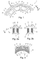
- the coil elements 4 are arranged along the circumferential direction U of the stator housing 2 adjacent to each other in this and each have a radially outwardly projecting fastening projection 5, by means of which they are supported in a state fastened to the stator housing 2 on this or dig into this.
- FIG. 2a a coil element 4 is shown in a separate, enlarged view.
- the coil element 4 has a main section 7 extending in the mounted state along a radial direction R of the stator housing 2, on which a stator winding 10 is wound.
- the main section 7 extends radially outward into an outer end section 8 projecting on both sides along the circumferential direction U and radially inward on both sides the circumferential direction U projecting inner end portion 9 via.
- the terms "radially inward” and “radially” on the outside refer to a state of the coil elements 4 mounted on the stator housing 2
- FIG. 3 shows in a partial view by way of example three wound with a respective stator winding 10 and mounted on the stator housing 2 coil elements 4.
- Such a trained coil element 4 allows easy winding with a respective stator winding 10 before mounting the coil elements 4 on the stator housing 2.
- the two end sections 8, 9 may additionally be formed as magnetic pole pieces, by means of which the field line profile of the stator magnetic field generated by the coil elements 4 can be improved ,
- an electrically insulating material for example, in the manner of an electrically insulating coating, are attached.
- the coil elements 4 can be fixed to the stator housing 2 in a simple yet mechanically stable manner, preferably by means of press-fitting.
- the coil elements 4 are first attached to each other like a chain and then pressed by means of a press tool as a unit in the stator housing 2.
- the fastening projections 5 allow a comfortable implementation of the press-fitting process.
- the stator arrangement 1 Due to the interspace 6 provided between the coil elements 4 and the stator housing 2, the stator arrangement 1 has a reduced dead weight compared with conventional stator arrangements.
- the intermediate space 6 can after mounting the coil elements 4 on the stator housing 2 on advantageous-hafte Way electrical line strands (not shown) are housed, which can be electrically connected to the provided on the coil elements 4 stator windings 10 so that they are electrically guided to the outside.
- the gap 6 is divided by means of the fastening projections 5 in a plurality of ring segment-like part-spaces 11.
- the fastening projections 5 there are separate spaces 11 for accommodating electrical lines.
- the partial spaces 11 may have different spatial geometries.
- each fastening projection 5 a recess 21 extending in the axial direction A of the stator housing 2, in particular in the manner of a groove, may be provided, such as the FIG. 2a can be seen in detail.
- This allows a particularly simple press-fitting of the fastening projections 5 in the stator housing 2, because by means of the recesses 21, the contact surface can be reduced when pressing the coil elements 4 in the stator housing 2 and thus the contact pressure can be increased.
- FIG. 2b is a variant of the coil element 4 of FIG. 2a shown, according to which instead of a single fastening projection 5 each two in the circumferential direction U offset from each other arranged mounting projections 5 are provided.
- FIG. 4 From the representation of FIG. 4 takes it that two in the fixed state on the stator housing 2 adjacent coil elements 4 each by means of radially outer end portion 8 are secured together.
- two adjacent coil elements 4 is at the radially outer end portion 8 each projecting in the circumferential direction U projection 13 (see also Fig. 2 ) and an opposite to the circumferential direction U open and complementary to the projection 13 recess 12 is provided.
- the projection 13 of a first coil element 4 engages in the respective recess 13 of a second coil element 4 adjacent to the first coil element 4 in the circumferential direction U.
- FIG. 5 clearly what an enlarged view of the in the FIG. 4 area indicated by "V".
- the projection 13 in the cross section of the stator assembly 1 may be formed like a circle segment.
- the respective recess 12 is substantially, but not completely complementary to the circular segment-like projection 13 formed such that a respective received in a recess 12 projection 13 with its outer surface 14 is not completely against a complementary to this outer surface 14 outer surface 15 of the recess 12.
- FIG. 5 can be realized by a not completely complementary formation of the surface contours of recess 12 and projection 13 between the projection 13 and the recess 12, a gap 16 between a groove bottom 17 of the recess 12 and the projection 13.
- the projection 13 as in the FIG. 5 shown in cross-section a circular segment-like, in particular a semi-circular, surface contour 18 having a predetermined first radius of curvature r 1 .
- the recess 12 in cross-section a first segment of a circle-like surface contour 19, which merges in the groove bottom 17 to a second surface contour 20, wherein the two surface contours having a second radius of curvature r 2 which is larger than the first radius of curvature r. 1
- the projection 13 is located only in two areas 21 a, 21 b in the recess 12 of the adjacent coil element 14, which are located laterally from the groove base 17 and the space 16. This allows a particularly stable attachment of two adjacent coil elements 4 to each other.
Landscapes
- Engineering & Computer Science (AREA)
- Power Engineering (AREA)
- Windings For Motors And Generators (AREA)
- Insulation, Fastening Of Motor, Generator Windings (AREA)
- Motor Or Generator Frames (AREA)
Abstract
Description
- Die Erfindung betrifft eine Statoranordnung für einen Elektromotor sowie einen Elektromotor mit einer solchen Statoranordnung.
- Herkömmliche Rotor- und Statoranordnungen für Elektromotoren mit aus mehreren Segmenten zusammengesetzten Statoren bzw. Rotoren sind aus dem Stand der Technik bekannt.
- Die
DE 10 2009 052 596 A1 offenbart einen Rotor für einen Elektromotor, der aus Einzelsegmenten gebildet ist, wobei jedes Einzelsegment ein erstes Teil aufweist, das in zusammengebautem Zustand mit einem zweiten korrespondierenden Teil des benachbarten Einzelsegmentes in Kontakt steht. Die beiden zueinander benachbarten Teile sind derart ausgebildet, dass sich ein Formschluss zwischen dem ersten Teil und dem zweiten Teil in radialer Richtung und in Umfangsrichtung ergibt. Durch den Formschluss in radialer Richtung und in Umfangsrichtung bildet sich eine selbsttragende Ringstruktur des zusammengebauten Rotors. - Die
DE 100 37 410 A1 beschreibt einen Elektromotor mit einem Rotor und einem Stator, welche beide jeweils einteilig ausgebildet und aus jeweils einem Band ge-wickelt sind. Der Stator ist auf der nach innen weisenden Seite mit Schlitzen zur Aufnahme von elektrischen Wicklungen versehen; jeweils zwei aufeinander folgende Schlitze weisen den gleichen Abstand voneinander auf und sind durch einen Steg voneinander getrennt, dessen Fuß mit einem ringförmigen Joch verbunden ist und die Schlitze nach außen teilweise begrenzt. - Nachteilig bei den bekannten Elektromotoren ist jedoch, dass diese mit ihrem jeweiligen Stator flächig an einem diesen umgebenden Gehäuse anliegen, wodurch insbesondere das Einpressen des Stators in das Gehäuse schwierig ist.
- Die vorliegende Erfindung beschäftigt sich mit dem Problem, bei der Herstellung von Statoranordnungen für Elektromotoren neue Wege aufzuzeigen.
- Dieses Problem wird durch den Gegenstand der unabhängigen Patentansprüche gelöst. Bevorzugte Ausführungsformen sind Gegenstand der abhängigen Patentansprüche.
- Die Erfindung beruht auf dem allgemeinen Gedanken, eine ein ringartig ausgebildetes Statorgehäuse aufweisende Statoranordnung mit einer Mehrzahl von im Statorgehäuse benachbart zueinander angeordneten Spulenelemente zu versehen, wobei die Spulenelemente jeweils einen radial nach außen abstehenden und kurvenartig wirkenden Befestigungsvorsprung aufweisen, mittels welchem sich die Spulenelemente derart am Statorgehäuse abstützen, dass zwischen diesen und den Spulenelementen ein sich in Umfangsrichtung des Statorgehäuses erstreckender Zwischenraum ausgebildet wird. In diesem Zwischenraum können nach einer Montage der Spulenelemente auf vorteilhafte Weise elektrische Leitungsbauteile wie zum Beispiel elektrische Leitungsstränge o.ä. untergebracht werden, welche es gestatten, auf den Spulenelementen vorgesehene Statorwicklungen elektrisch nach außen zu führen. Die radial nach außen vorstehenden Befestigungsvorsprünge erlauben beim Einpressen des Stators in das Statorgehäuse zudem ein Eingraben der Befestigungsvorsprünge in das Statorgehäuse, wodurch die Spulenelemente fest im Statorgehäuse verankert sind. Zudem kann durch die Befestigungsabschnitte ein dazwischen liegender Zwischenraum geschaffen werden, der für andere Aufgaben nutzbar ist. Die radial nach außen vorstehenden Befestigungsvorsprünge erlauben somit eine einfache und dennoch mechanisch stabile Befestigung der Spulenelemente, vorzugsweise mittels Einpressen, am Statorgehäuse durch Verwendung eines geeigneten Einpresswerkzeugs. Aufgrund des zwischen den Spulenelementen und dem Statorgehäuse vorgesehenen Zwischenraums weist die Statoranordnung gegenüber herkömmlichen Statoranordnungen ein reduziertes Gewicht auf.
- Bei einer bevorzugten Ausführungsform können die Spulenelemente im am Statorgehäuse montierten Zustand mittels der radial nach außen abstehenden Befestigungsvorsprünge in das Statorgehäuse eingepresst sein. Zur Montage der Spulenelemente können diese, wie im Folgenden noch genauer erläutert wird, zunächst kettenartig aneinander befestigt werden und dann mittels eines geeigneten Einpresswerkzeugs als Einheit in das Statorgehäuse eingepresst werden.
- Besonders zweckmäßig wird der Zwischenraum mittels der Befestigungsvorsprünge in eine Mehrzahl von ringsegmentartig ausgebildeten Teil-Zwischenräumen unterteilt. Dies stehen zur Unterbringung von elektrischen Leitungen zur Verfügung, mittels welcher die auf den einzelnen Spulenelementen angebrachten Statorwicklungen elektrisch kontaktiert werden können. Je nach Ausgestaltung der radial nach außen abstehenden Vorsprünge sind für die Teil-Zwischenräume verschiedene Geometrien vorstellbar.
- Bei einer vorteilhaften Weiterbildung ist in jedem Befestigungsvorsprung radial außen eine sich in axialer Richtung des Statorgehäuses erstreckende Ausnehmung, insbesondere in der Art einer Nut, vorgesehen. Dies ermöglicht ein besonders einfaches Einpressen der Befestigungsvorsprünge in das Statorgehäuse, da mittels der Ausnehmung die Kontaktfläche beim Einpressen des jeweiligen Spulenelemente in das Statorgehäuse reduziert und folglich der vom Befestigungsvorsprung erzeugte Anpressdruck auf das Statorgehäuse erhöht werden kann.
- Bei einer besonders vorteilhaften Ausführungsform weist jedes Spulenelement einen sich im montierten Zustand entlang der radialen Richtung des Statorgehäuses erstreckenden Hauptabschnitt auf, auf welchem eine Statorwicklung angeordnet, insbesondere aufgewickelt, ist. Der Hauptabschnitt geht radial außen in einen beidseitig entlang der Umfangsrichtung vom Hauptabschnitt abstehenden äußeren Endabschnitt und radial innen in einen beidseitig entlang Umfangsrichtung vom Hauptabschnitt abstehenden inneren Endabschnitt über. Ein derartig ausgebildetes Spulenelement gestattet ein zuverlässiges Bewickeln der Spulenelemente mit einer jeweiligen Statorwicklung, wobei die beiden Endabschnitte zusätzlich als Polschuhe ausgebildet sein können, mittels welcher der Feldlinienverlauf des von den Spulenelementen erzeugten Stator-Magnetfelds verbessert werden kann. Zwischen Statorwicklung und dem Hauptabschnitt kann ein elektrisch isolierendes Material, beispielsweise in der Art einer elektrisch isolierenden Beschichtung.
- Besonders bevorzugt können zwei in dem am Statorgehäuse befestigten Zustand benachbarte Spulenelemente jeweils mittels des radial äußeren Endabschnitts aneinander befestigt sein. Zur Befestigung zweier benachbarter Spulenelemente sind am radial äußeren Endabschnitt jeweils ein in Umfangsrichtung abstehender Vorsprung sowie eine entgegen der Umfangsrichtung offene und zum Vorsprung komplementäre Ausnehmung vorgesehen. In dem am Statorgehäuse befestigten Zustand greift der Vorsprung eines ersten Spulenelements in die jeweilige Ausnehmung eines in Umfangsrichtung zum ersten Spulenelement benachbarten zweiten Spulenelements ein oder umgekehrt. Dies ermöglicht eine stabile, kettenartige Montage der Spulenelemente aneinander, bevor diese dann ein einem weiteren Montageschritt als Einheit, beispielsweise mittels Einpressen, am Statorgehäuse befestigt werden.
- Um eine mechanisch möglichst stabile Befestigung zweier benachbarter Spulenelemente aneinander zu erzielen, kann bei einer weiteren bevorzugten Ausführungsform der am radial äußeren Endabschnitt des jeweiligen Spulenelements vorgesehen Vorsprung im Querschnitt der Statoranordnung kreissegmentartig ausgebildet sein. Die jeweilige Ausnehmung ist dabei derart im Wesentlichen komplementär zum kreissegmentartigen Vorsprung ausgebildet, dass ein jeweiliger in einer Ausnehmung aufgenommener Vorsprung mit seiner Außenfläche nicht vollständig an einer zu dieser Außenfläche komplementären Außenfläche der Ausnehmung anliegt.
- Besonders zweckmäßig kann in einem aneinander befestigten Zustand zweier benachbarter Spulenelemente wenigstens ein Zwischenraum zwischen einem Nutengrund der Ausnehmung und dem Vorsprung ausgebildet sein.
- Vorteilhafterweise kann der Vorsprung im Querschnitt eine kreissegmentartige, insbesondere eine halbkreisartige, Oberflächenkontur mit einem vorbestimmten ersten Krümmungsradius aufweisen. Entsprechend weist die Ausnehmung im Querschnitt eine erste kreissegmentartige Oberflächenkontur auf, welches im Nutengrund in eine zweite kreissegmentartige Oberflächenübergeht, wobei die beiden Oberflächenkonturen jeweils einen zweiten Krümmungsradius aufweisen, der größer ist als der erste Krümmungsradius. Auf diese Weise kann der vorangehend vorgeschlagene Zwischenraum zwischen dem Nutengrund der Ausnehmung und dem zur Ausnehmung komplementären Vorsprung erzeugt werden.
- Bei einer besonders zweckmäßigen Ausführungsform können die Spulenelemente als Blechstanzteile ausgebildet sein, was eine besonders kostengünstige Herstellung der Spulenelemente erlaubt. Zweckmäßigerweise ist auch das Statorgehäuse aus einem Metall, vorzugsweise Aluminium, hergestellt, was ein Einpressen der Blechstanzteile (Spulenelemente) sowie ein Eingraben derselben in das Statorgehäuse erleichtert.
- Die Erfindung betrifft des Weiteren einen Elektromotor mit einer Statoranordnung mit einem oder mehreren der vorangehend genannten Merkmale sowie mit einem relativ zur Statoranordnung drehverstellbaren Rotor.
- Weitere wichtige Merkmale und Vorteile der Erfindung ergeben sich aus den Unteransprüchen, aus den Zeichnungen und aus der zugehörigen Figurenbeschreibung anhand der Zeichnungen.
- Es versteht sich, dass die vorstehend genannten und die nachstehend noch zu erläuternden Merkmale nicht nur in der jeweils angegebenen Kombination, sondern auch in anderen Kombinationen oder in Alleinstellung verwendbar sind, ohne den Rahmen der vorliegenden Erfindung zu verlassen.
- Bevorzugte Ausführungsbeispiele der Erfindung sind in den Zeichnungen dargestellt und werden in der nachfolgenden Beschreibung näher erläutert, wobei sich gleiche Bezugszeichen auf gleiche oder ähnliche oder funktional gleiche Komponenten beziehen.
- Es zeigen, jeweils schematisch
- Fig. 1
- eine grobschematische Teilansicht einer erfindungsgemäßen Statoranordnung,
- Fig. 2a
- eine Detailansicht eines Spulenelements der Statoranordnung,
- Fig. 2b
- eine Variante des Spulenelements der
Figur 2a , - Fig. 3
- eine alternative Darstellung der Statoranordnung der
Figur 1 mit bewickelten Spulenelementen, - Fig. 4
- eine weitere alternative Darstellung der Statoranordnung der
Figur 1 , in welcher gezeigt ist, wie benachbarte Spulenelemente aneinander befestigt sind, - Fig. 5
- eine Detailansicht der
Figur 4 , in welcher zwei benachbarte und aneinander befestigte Spulenelemente gezeigt sind. - In der
Figur 1 ist ein Ausschnitt einer erfindungsgemäßen Statoranordnung für einen Elektromotor grobschematisch im Querschnitt dargestellt und mit 1 bezeichnet. Die Statoranordnung 1 umfasst ein im Querschnitt ringartig ausgebildetes Statorgehäuse 2 sowie eine Mehrzahl von in einem Statorgehäuse 3 benachbart zueinander angeordneten Spulenelementen 4. Das gesamte Statorgehäuse 3 kann in der Art eines Zylinders ausgebildet sein und aus einem Metall, vorzugsweise Aluminium, hergestellt sein, was ein Einpressen der als Blechstanzteile ausgebildeten Spulenelemente 4 in das Statorgehäuse 3 erleichtert, wenn diese am Statorgehäuse 3 befestigt werden sollen. Die Spulenelemente 4 sind entlang der Umfangsrichtung U des Statorgehäuses 2 benachbart zueinander in diesem angeordnet und weisen jeweils einen radial nach außen abstehenden Befestigungsvorsprung 5 auf, mittels welchem sie sich in einem am Statorgehäuse 2 befestigten Zustand an diesem abstützen bzw. in dieses eingraben. - In der
Figur 2a ist nun ein Spulenelement 4 in einer separaten, vergrößerten Darstellung gezeigt. Das Spulenelement 4 weist einen sich im montierten Zustand entlang einer radialen Richtung R des Statorgehäuses 2 erstreckenden Hauptabschnitt 7 auf, auf welchem eine Statorwicklung 10 aufgewickelt ist. Der Hauptabschnitt 7 geht radial außen in einen beidseitig entlang der Umfangsrichtung U abstehenden äußeren Endabschnitt 8 und radial innen in einen beidseitig entlang der Umfangsrichtung U abstehenden inneren Endabschnitt 9 über. Die Begriffe "radial innen" und "radial" außen beziehen sich dabei auf einen am Statorgehäuse 2 montierten Zustand der Spulenelemente 4. DieFigur 3 zeigt in einer Teilansicht exemplarisch drei mit einer jeweiligen Statorwicklung 10 bewickelte und am Statorgehäuse 2 montierte Spulenelemente 4. Ein derartig ausgebildetes Spulenelement 4 (vgl. hierzu wiederFig. 2a ) gestattet ein einfaches Bewickeln mit einer jeweiligen Statorwicklung 10 vor der Montage der Spulenelemente 4 am Statorgehäuse 2. Die beiden Endabschnitte 8, 9 können zusätzlich als magnetische Polschuhe ausgebildet sein, mittels welcher der Feldlinienverlauf des von den Spulenelementen 4 erzeugten Stator-Magnetfelds verbessert werden kann. Zwischen Statorwicklung 10 und dem Hauptabschnitt 7 kann ein elektrisch isolierendes Material, beispielsweise in der Art einer elektrisch isolierenden Beschichtung, angebracht werden. - Betrachtet man nun wieder die Darstellung der
Figur 1 , so erkennt man, dass mittels der Befestigungsvorsprünge 5 zwischen den Spulenelementen 4 und dem Statorgehäuse 2 ein sich in Umfangsrichtung U des Statorgehäuses 2 erstreckender Zwischenraum 6 ausgebildet wird. Mittels der radial nach außen vorstehenden Befestigungsvorsprünge 5 können die Spulenelemente 4 auf einfache und dennoch mechanisch stabile Weise, vorzugsweise mittels Einpressen, am Statorgehäuse 2 fixiert werden. Zur Montage werden die Spulenelemente 4 zunächst kettenartig aneinander befestigt und anschließend mittels eines Einpresswerkzeugs als Einheit in das Statorgehäuse 2 eingepresst. Dabei erlauben die Befestigungsvorsprünge 5 eine komfortable Durchführung des Einpressvorgangs. - Aufgrund des zwischen den Spulenelementen 4 und dem Statorgehäuse 2 vorgesehenen Zwischenraums 6 weist die Statoranordnung 1 gegenüber herkömmlichen Statoranordnungen ein reduziertes Eigengewicht auf. Im Zwischenraum 6 können nach der Montage der Spulenelemente 4 am Statorgehäuse 2 auf vorteil-hafte Weise elektrische Leitungsstränge (nicht gezeigt) untergebracht werden, welche elektrisch mit den auf den Spulenelementen 4 vorgesehenen Statorwicklungen 10 verbunden werden können, so dass diese elektrisch nach außen geführt sind.
- Aus der
Figur 1 lässt sich ferner entnehmen, dass der Zwischenraum 6 mittels der Befestigungsvorsprünge 5 in eine Mehrzahl von ringsegmentartig ausgebildeten Teil-Zwischenräumen 11 unterteilt wird. Somit stehen zur elektrischen Kontaktierung der auf den Spulenelementen 4 angebrachten Statorwicklungen 10 jeweils separate Zwischenräume 11 zur Unterbringung von elektrischen Leitungen zur Verfügung. Je nach Ausgestaltung der radial nach außen abstehenden Befestigungsvorsprünge 5 können die Teil-Zwischenräume 11 unterschiedliche Raumgeometrien aufweisen. - Zusätzlich kann in jedem Befestigungsvorsprung 5 eine sich in axialer Richtung A des Statorgehäuses 2 erstreckende Ausnehmung 21, insbesondere in der Art einer Nut, vorgesehen sein, wie die
Figur 2a im Einzelnen erkennen lässt. Dies ermöglicht ein besonders einfaches Einpressen der Befestigungsvorsprünge 5 in das Statorgehäuse 2, denn mittels der Ausnehmungen 21 kann die Kontaktfläche beim Einpressen der Spulenelemente 4 in das Statorgehäuse 2 reduziert und somit der Anpressdruck erhöht werden. - In der
Figur 2b ist eine Variante des Spulenelements 4 derFigur 2a gezeigt, gemäß welcher anstelle eines einzigen Befestigungsvorsprungs 5 jeweils zwei in Umfangsrichtung U zueinander versetzt angeordnete Befestigungsvorsprünge 5 vorgesehen sind. - Aus der Darstellung der
Figur 4 entnimmt man, dass zwei in dem am Statorgehäuse 2 befestigten Zustand benachbarte Spulenelemente 4 jeweils mittels des radial äußeren Endabschnitts 8 aneinander befestigt sind. Zur Befestigung zweier benachbarter Spulenelemente 4 ist am radial äußeren Endabschnitt 8 jeweils ein in Umfangsrichtung U abstehender Vorsprung 13 (vgl. auchFig. 2 ) sowie eine entgegen der Umfangsrichtung U offene und zum Vorsprung 13 komplementäre Ausnehmung 12 vorgesehen. In dem am Statorgehäuse 2 befestigten Zustand greift der Vorsprung 13 eines ersten Spulenelements 4 in die jeweilige Ausnehmung 13 eines in Umfangsrichtung U zum ersten Spulenelement 4 benachbarten zweiten Spulenelements 4 ein. Dies wird aus der Darstellung derFigur 5 deutlich, welche eine vergrößerte Darstellung des in derFigur 4 mit "V" bezeichneten Bereichs zeigt. - Um eine mechanisch möglichst stabile Befestigung zweier benachbarter Spulenelemente 4 aneinander zu erreichen, kann der Vorsprung 13 im Querschnitt der Statoranordnung 1 kreissegmentartig ausgebildet sein. Die jeweilige Ausnehmung 12 ist dabei derart im Wesentlichen, aber nicht vollständig komplementär zum kreissegmentartigen Vorsprung 13 ausgebildet, dass ein jeweiliger in einer Ausnehmung 12 aufgenommener Vorsprung 13 mit seiner Außenfläche 14 nicht vollständig an einer zu dieser Außenfläche 14 komplementären Außenfläche 15 der Ausnehmung 12 anliegt.
- Wie in der
Figur 5 gezeigt kann durch eine nicht vollständig komplementäre Ausbildung der Oberflächenkonturen von Ausnehmung 12 und Vorsprung 13 zwischen dem Vorsprung 13 und der Ausnehmung 12 ein Zwischenraum 16 zwischen einem Nutengrund 17 der Ausnehmung 12 und dem Vorsprung 13 realisiert werden. - Besonders zweckmäßig kann der Vorsprung 13 wie in der
Figur 5 gezeigt im Querschnitt eine kreissegmentartige, insbesondere eine halbkreisartige, Oberflächenkontur 18 mit einem vorbestimmten ersten Krümmungsradius r1 aufweisen. In diesem Fall weist die Ausnehmung 12 im Querschnitt eine erste kreissegmentartige Oberflächenkontur 19 auf, welches im Nutengrund 17 in eine zweite Oberflächenkontur 20 übergeht, wobei die beiden Oberflächenkonturen jeweils einen zweiten Krümmungsradius r2 aufweisen, der größer ist als der erste Krümmungsradius r1. Auf diese Weise kann der vorangehend erwähnte Zwischenraum 16 zwischen dem Nutengrund 17 der Ausnehmung 12 und dem Vorsprung 13 erzeugt werden. In dem in derFigur 5 gezeigten Beispiel liegt der Vorsprung 13 nur in zwei Bereichen 21 a, 21 b in der Ausnehmung 12 des benachbarten Spulenelements 14 an, die sich seitlich vom Nutengrund 17 bzw. dem Zwischenraum 16 befinden. Dies ermöglicht eine besonders stabile Befestigung zweier benachbarter Spulenelemente 4 aneinander.
Claims (11)
- Statoranordnung (1) für einen Elektromotor,- mit einem im Querschnitt ringartig ausgebildeten Statorgehäuse (2),- mit einer Mehrzahl von im Statorgehäuse (2) benachbart zueinander angeordneten Spulenelementen (4) zur Aufnahme einer jeweiligen Statorwicklung (10),- wobei die Spulenelemente (4) in Umfangsrichtung (U) des Statorgehäuses (2) benachbart zueinander in diesem angeordnet sind und jeweils in einem im Statorgehäuse (2) montierten Zustand wenigstens einen radial nach außen abstehenden Befestigungsvorsprung (5) aufweisen, mittels welchem sich die Spulenelemente (4) derart radial nach außen am Statorgehäuse (2) abstützen, dass zwischen diesem und den Spulenelementen (4) ein sich in Umfangsrichtung (U) erstreckender Zwischenraum (6) ausgebildet ist.
- Statoranordnung nach Anspruch 1,
dadurch gekennzeichnet, dass
die Spulenelemente (4) im am Statorgehäuse (2) montierten Zustand mittels der radial nach außen abstehenden Befestigungsvorsprünge (5) in das Statorgehäuse (2) eingepresst sind. - Statoranordnung nach Anspruch 1 oder 2,
dadurch gekennzeichnet, dass
der Zwischenraum (6) mittels der Befestigungsvorsprünge (5) in eine Mehrzahl von ringsegmentartig ausgebildeten Teil-Zwischenräumen (11) unterteilt wird. - Statoranordnung nach einem der Ansprüche 1 bis 3,
dadurch gekennzeichnet, dass
in jedem Befestigungsvorsprung (5) eine sich in axialer Richtung (A) des Statorgehäuses (2) erstreckende Ausnehmung (21), insbesondere in der Art einer Nut, vorgesehen ist. - Statoranordnung nach einem der vorhergehenden Ansprüche,
dadurch gekennzeichnet, dass- jedes Spulenelement (4) einen sich im montierten Zustand entlang der radialen Richtung (R) des Statorgehäuses (2) erstreckenden Hauptabschnitt (7) aufweist, auf welchem eine Statorwicklung (10) angeordnet, insbesondere aufgewickelt, ist,- der Hauptabschnitt (7) radial außen in einen beidseitig entlang der Umfangsrichtung (U) abstehenden äußeren Endabschnitt (8) und radial innen in einen beidseitig entlang der Umfangsrichtung (U) abstehenden inneren Endabschnitt (9) übergeht. - Statoranordnung nach Anspruch 5,
dadurch gekennzeichnet, dass- zwei in dem am Statorgehäuse (2) befestigten Zustand benachbarte Spulenelemente (4) jeweils mittels ihres radial äußeren Endabschnitts (8) aneinander befestigt sind,- zur Befestigung zweier benachbarter Spulenelemente (4) am radial äußeren Endabschnitt (8) jeweils ein in Umfangsrichtung (U) abstehender Vorsprung (13) und eine entgegen der Umfangsrichtung (U) offene und zum Vorsprung (13) komplementäre Ausnehmung (12) vorgesehen sind,- in dem am Statorgehäuse (2) befestigten Zustand der Vorsprung (13) eines ersten Spulenelements (4) in die jeweilige Ausnehmung (12) eines in Umfangsrichtung (U) zum ersten Spulenelement (4) benachbarten zweiten Spulenelements (4) eingreift. - Statoranordnung nach Anspruch 6,
dadurch gekennzeichnet, dass- der am radial äußeren Endabschnitt (8) des jeweiligen Spulenelements (4) vorgesehen Vorsprung (13) im Querschnitt kreissegmentartig ausgebildet ist,- die jeweilige Ausnehmung (12) derart im Wesentlichen komplementär zum kreissegmentartig Vorsprung (13) ausgebildet ist, dass ein jeweiliger in einer Ausnehmung (12) aufgenommener Vorsprung (13) mit seiner Außenfläche (14) nur bereichsweise an einer zu dieser Außenfläche (14) komplementären Außenfläche (15) der Ausnehmung (12) anliegt. - Statoranordnung nach Anspruch 6 oder 7,
dadurch gekennzeichnet, dass
in einem in der Ausnehmung (13) aufgenommenen Zustand des jeweiligen zur Ausnehmung (13) komplementären Vorsprungs (12) wenigstens ein Zwischenraum (16) zwischen einem Nutengrund (17) der Ausnehmung (13) und dem Vorsprung (13) ausgebildet ist. - Statoranordnung nach einem der Ansprüche 6 bis 8,
dadurch gekennzeichnet, dass- der Vorsprung (13) im Querschnitt eine kreissegmentartige, insbesondere eine halbkreisartige, Oberflächenkontur (18) mit einem vorbestimmten ersten Krümmungsradius (r1) aufweist,- die Ausnehmung im Querschnitt eine erste kreissegmentartige Oberflächenkontur (19) aufweist, welches im Nutengrund (17) in ein zweite kreissegmentartige Oberflächenkontur (20) übergeht, wobei die beiden Oberflächenkonturen (19, 20) jeweils einen zweiten Krümmungsradius (r2) aufweisen, der größer ist als der erste Krümmungsradius (r1). - Statoranordnung nach einem der vorhergehenden Ansprüche,
dadurch gekennzeichnet, dass
die Spulenelemente (4) als Blechstanzteile ausgebildet sind. - Elektromotor,- mit einer Statoranordnung (1) nach einem der vorhergehenden Ansprüche,- mit einem relativ zur Statoranordnung (1) drehverstellbaren Rotor.
Applications Claiming Priority (1)
| Application Number | Priority Date | Filing Date | Title |
|---|---|---|---|
| DE201310219535 DE102013219535A1 (de) | 2013-09-27 | 2013-09-27 | Statoranordnung für einen Elektromotor |
Publications (3)
| Publication Number | Publication Date |
|---|---|
| EP2854257A2 true EP2854257A2 (de) | 2015-04-01 |
| EP2854257A3 EP2854257A3 (de) | 2015-11-25 |
| EP2854257B1 EP2854257B1 (de) | 2017-12-27 |
Family
ID=51212765
Family Applications (1)
| Application Number | Title | Priority Date | Filing Date |
|---|---|---|---|
| EP14178250.8A Not-in-force EP2854257B1 (de) | 2013-09-27 | 2014-07-24 | Statoranordnung für einen Elektromotor |
Country Status (2)
| Country | Link |
|---|---|
| EP (1) | EP2854257B1 (de) |
| DE (1) | DE102013219535A1 (de) |
Citations (2)
| Publication number | Priority date | Publication date | Assignee | Title |
|---|---|---|---|---|
| DE10037410A1 (de) | 2000-08-01 | 2002-02-14 | Abb Research Ltd | Rotierende elektrische Maschine und Verfahren zu deren Herstellung |
| DE102009052596A1 (de) | 2009-11-10 | 2011-05-12 | Daimler Ag | Rotor einer elektrischen Maschine |
Family Cites Families (10)
| Publication number | Priority date | Publication date | Assignee | Title |
|---|---|---|---|---|
| JP3651263B2 (ja) * | 1998-05-29 | 2005-05-25 | 日本精工株式会社 | 分割磁極型電動モータ |
| JP3661589B2 (ja) * | 2000-11-21 | 2005-06-15 | 日産自動車株式会社 | モータまたは発電機 |
| JP3603784B2 (ja) * | 2000-12-14 | 2004-12-22 | 日産自動車株式会社 | 回転電機 |
| JP2003032936A (ja) * | 2001-07-16 | 2003-01-31 | Matsushita Electric Ind Co Ltd | 電動機 |
| JP4546213B2 (ja) * | 2004-10-21 | 2010-09-15 | 本田技研工業株式会社 | モータおよびモータを搭載した電動パワーステアリング装置 |
| JP4807219B2 (ja) * | 2006-10-20 | 2011-11-02 | トヨタ自動車株式会社 | ステータコアおよび回転電機 |
| JP2009044880A (ja) * | 2007-08-09 | 2009-02-26 | Jtekt Corp | モータ及び電動パワーステアリング装置 |
| JP4758484B2 (ja) * | 2008-01-24 | 2011-08-31 | ダイキン工業株式会社 | 圧縮機 |
| DE102010007885A1 (de) * | 2010-02-13 | 2011-08-18 | Daimler AG, 70327 | Stator einer elektrischen Maschine |
| WO2014128938A1 (ja) * | 2013-02-22 | 2014-08-28 | 三菱電機株式会社 | 永久磁石埋込型電動機、圧縮機、および冷凍空調装置 |
-
2013
- 2013-09-27 DE DE201310219535 patent/DE102013219535A1/de not_active Withdrawn
-
2014
- 2014-07-24 EP EP14178250.8A patent/EP2854257B1/de not_active Not-in-force
Patent Citations (2)
| Publication number | Priority date | Publication date | Assignee | Title |
|---|---|---|---|---|
| DE10037410A1 (de) | 2000-08-01 | 2002-02-14 | Abb Research Ltd | Rotierende elektrische Maschine und Verfahren zu deren Herstellung |
| DE102009052596A1 (de) | 2009-11-10 | 2011-05-12 | Daimler Ag | Rotor einer elektrischen Maschine |
Also Published As
| Publication number | Publication date |
|---|---|
| EP2854257B1 (de) | 2017-12-27 |
| DE102013219535A1 (de) | 2015-04-02 |
| EP2854257A3 (de) | 2015-11-25 |
Similar Documents
| Publication | Publication Date | Title |
|---|---|---|
| WO2020099048A1 (de) | Stützeinrichtung für einen rotor einer fremderregten innenläufer-synchronmaschine bestehend aus einem stützring und einer sternscheibe | |
| DE102019202844A1 (de) | Fasererdungsbürste, Anordnung mit der Fasererdungsbürste und Verfahren zum Montieren der Anordnung | |
| DE102008004019B4 (de) | Jochaufbau für den Stator eines Anlassermotors | |
| DE102012222683A1 (de) | Elektrische Maschine | |
| DE102018208823A1 (de) | Kontaktierelement zur elektrischen Kontaktierung einer Welle einer elektrischen Antriebseinheit eines Kraftfahrzeugs, elektrische Antriebseinheit sowie Kraftfahrzeug | |
| DE1953642C3 (de) | Befestigung für eine feststehende, mit einer umhüllung versehene erregerwicklung einer elektrischen maschine der klauenpolbauart | |
| DE102013113363A1 (de) | Stator für einen elektronisch kommutierten Gleichstrommotor | |
| DE10228225B4 (de) | Verfahren und Anordnung zur Montage einer Stromerzeugereinheit | |
| EP2541740A1 (de) | Stator | |
| DE10331245B4 (de) | Bürstenmotor für elektrisches Lenkservosystem | |
| EP2410634B1 (de) | Elektrokleinmotor sowie Verfahren zur Herstellung eines Elektrokleinmotors | |
| DE102014220620A1 (de) | Anker, drehende elektrische Vorrichtung und Ankerherstellungsverfahren | |
| DE102012220629A1 (de) | Rotorträgervorrichtung für eine elektrische Maschine und entsprechende elektrische Maschine | |
| DE102016211833A1 (de) | Wicklungsträger | |
| DE102010033699A1 (de) | Schaltkopf für Elektromotoren sowie Verfahren zur Herstellung eines Kontaktringes für einen solchen Schaltkopf | |
| DE112014006556T5 (de) | Stator einer elektrischen Rotationsmaschine und Verfahren zur Herstellung desselben | |
| DE102008025512A1 (de) | Verfahren zum Zusammenbau des Stators einer elektrischen Maschine sowie elektrische Maschine | |
| DE102012222318A1 (de) | Zahnsegment-Spulen-Kombination für eine elektrische Maschine | |
| DE102012106224A1 (de) | Endkappenanordnung für einen Elektromotor | |
| EP2854257B1 (de) | Statoranordnung für einen Elektromotor | |
| DE102010005490A1 (de) | Rotor einer elektrischen Maschine und Verfahren zur Herstellung eines Rotors einer elektrischen Maschine | |
| EP2750269B1 (de) | Pumpenaggregat | |
| DE102009046530A1 (de) | Ankerbaugruppe und Elektromaschine mit einer Ankerbaugruppe | |
| DE102022133606A1 (de) | Lagerschildvorrichtung für eine Statorvorrichtung, Statorvorrichtung für eine elektrische Maschine, zugehöriges Herstellungsverfahren und elektrische Maschine zum Antreiben eines Fahrzeugs | |
| DE102009020327A1 (de) | Resolver |
Legal Events
| Date | Code | Title | Description |
|---|---|---|---|
| PUAI | Public reference made under article 153(3) epc to a published international application that has entered the european phase |
Free format text: ORIGINAL CODE: 0009012 |
|
| 17P | Request for examination filed |
Effective date: 20140724 |
|
| AK | Designated contracting states |
Kind code of ref document: A2 Designated state(s): AL AT BE BG CH CY CZ DE DK EE ES FI FR GB GR HR HU IE IS IT LI LT LU LV MC MK MT NL NO PL PT RO RS SE SI SK SM TR |
|
| AX | Request for extension of the european patent |
Extension state: BA ME |
|
| PUAL | Search report despatched |
Free format text: ORIGINAL CODE: 0009013 |
|
| AK | Designated contracting states |
Kind code of ref document: A3 Designated state(s): AL AT BE BG CH CY CZ DE DK EE ES FI FR GB GR HR HU IE IS IT LI LT LU LV MC MK MT NL NO PL PT RO RS SE SI SK SM TR |
|
| AX | Request for extension of the european patent |
Extension state: BA ME |
|
| RIC1 | Information provided on ipc code assigned before grant |
Ipc: H02K 1/18 20060101ALI20151021BHEP Ipc: H02K 1/14 20060101AFI20151021BHEP |
|
| R17P | Request for examination filed (corrected) |
Effective date: 20160429 |
|
| RBV | Designated contracting states (corrected) |
Designated state(s): AL AT BE BG CH CY CZ DE DK EE ES FI FR GB GR HR HU IE IS IT LI LT LU LV MC MK MT NL NO PL PT RO RS SE SI SK SM TR |
|
| 17Q | First examination report despatched |
Effective date: 20160819 |
|
| GRAP | Despatch of communication of intention to grant a patent |
Free format text: ORIGINAL CODE: EPIDOSNIGR1 |
|
| INTG | Intention to grant announced |
Effective date: 20170919 |
|
| GRAS | Grant fee paid |
Free format text: ORIGINAL CODE: EPIDOSNIGR3 |
|
| GRAA | (expected) grant |
Free format text: ORIGINAL CODE: 0009210 |
|
| AK | Designated contracting states |
Kind code of ref document: B1 Designated state(s): AL AT BE BG CH CY CZ DE DK EE ES FI FR GB GR HR HU IE IS IT LI LT LU LV MC MK MT NL NO PL PT RO RS SE SI SK SM TR |
|
| REG | Reference to a national code |
Ref country code: GB Ref legal event code: FG4D Free format text: NOT ENGLISH |
|
| REG | Reference to a national code |
Ref country code: CH Ref legal event code: EP |
|
| REG | Reference to a national code |
Ref country code: AT Ref legal event code: REF Ref document number: 959083 Country of ref document: AT Kind code of ref document: T Effective date: 20180115 |
|
| REG | Reference to a national code |
Ref country code: IE Ref legal event code: FG4D Free format text: LANGUAGE OF EP DOCUMENT: GERMAN |
|
| REG | Reference to a national code |
Ref country code: DE Ref legal event code: R096 Ref document number: 502014006721 Country of ref document: DE |
|
| PG25 | Lapsed in a contracting state [announced via postgrant information from national office to epo] |
Ref country code: LT Free format text: LAPSE BECAUSE OF FAILURE TO SUBMIT A TRANSLATION OF THE DESCRIPTION OR TO PAY THE FEE WITHIN THE PRESCRIBED TIME-LIMIT Effective date: 20171227 Ref country code: FI Free format text: LAPSE BECAUSE OF FAILURE TO SUBMIT A TRANSLATION OF THE DESCRIPTION OR TO PAY THE FEE WITHIN THE PRESCRIBED TIME-LIMIT Effective date: 20171227 Ref country code: NO Free format text: LAPSE BECAUSE OF FAILURE TO SUBMIT A TRANSLATION OF THE DESCRIPTION OR TO PAY THE FEE WITHIN THE PRESCRIBED TIME-LIMIT Effective date: 20180327 |
|
| REG | Reference to a national code |
Ref country code: NL Ref legal event code: MP Effective date: 20171227 |
|
| REG | Reference to a national code |
Ref country code: LT Ref legal event code: MG4D |
|
| PG25 | Lapsed in a contracting state [announced via postgrant information from national office to epo] |
Ref country code: LV Free format text: LAPSE BECAUSE OF FAILURE TO SUBMIT A TRANSLATION OF THE DESCRIPTION OR TO PAY THE FEE WITHIN THE PRESCRIBED TIME-LIMIT Effective date: 20171227 Ref country code: RS Free format text: LAPSE BECAUSE OF FAILURE TO SUBMIT A TRANSLATION OF THE DESCRIPTION OR TO PAY THE FEE WITHIN THE PRESCRIBED TIME-LIMIT Effective date: 20171227 Ref country code: GR Free format text: LAPSE BECAUSE OF FAILURE TO SUBMIT A TRANSLATION OF THE DESCRIPTION OR TO PAY THE FEE WITHIN THE PRESCRIBED TIME-LIMIT Effective date: 20180328 Ref country code: BG Free format text: LAPSE BECAUSE OF FAILURE TO SUBMIT A TRANSLATION OF THE DESCRIPTION OR TO PAY THE FEE WITHIN THE PRESCRIBED TIME-LIMIT Effective date: 20180327 Ref country code: HR Free format text: LAPSE BECAUSE OF FAILURE TO SUBMIT A TRANSLATION OF THE DESCRIPTION OR TO PAY THE FEE WITHIN THE PRESCRIBED TIME-LIMIT Effective date: 20171227 |
|
| PG25 | Lapsed in a contracting state [announced via postgrant information from national office to epo] |
Ref country code: NL Free format text: LAPSE BECAUSE OF FAILURE TO SUBMIT A TRANSLATION OF THE DESCRIPTION OR TO PAY THE FEE WITHIN THE PRESCRIBED TIME-LIMIT Effective date: 20171227 |
|
| REG | Reference to a national code |
Ref country code: FR Ref legal event code: PLFP Year of fee payment: 5 |
|
| PG25 | Lapsed in a contracting state [announced via postgrant information from national office to epo] |
Ref country code: CZ Free format text: LAPSE BECAUSE OF FAILURE TO SUBMIT A TRANSLATION OF THE DESCRIPTION OR TO PAY THE FEE WITHIN THE PRESCRIBED TIME-LIMIT Effective date: 20171227 Ref country code: SK Free format text: LAPSE BECAUSE OF FAILURE TO SUBMIT A TRANSLATION OF THE DESCRIPTION OR TO PAY THE FEE WITHIN THE PRESCRIBED TIME-LIMIT Effective date: 20171227 Ref country code: EE Free format text: LAPSE BECAUSE OF FAILURE TO SUBMIT A TRANSLATION OF THE DESCRIPTION OR TO PAY THE FEE WITHIN THE PRESCRIBED TIME-LIMIT Effective date: 20171227 Ref country code: CY Free format text: LAPSE BECAUSE OF FAILURE TO SUBMIT A TRANSLATION OF THE DESCRIPTION OR TO PAY THE FEE WITHIN THE PRESCRIBED TIME-LIMIT Effective date: 20171227 Ref country code: ES Free format text: LAPSE BECAUSE OF FAILURE TO SUBMIT A TRANSLATION OF THE DESCRIPTION OR TO PAY THE FEE WITHIN THE PRESCRIBED TIME-LIMIT Effective date: 20171227 |
|
| PG25 | Lapsed in a contracting state [announced via postgrant information from national office to epo] |
Ref country code: IT Free format text: LAPSE BECAUSE OF FAILURE TO SUBMIT A TRANSLATION OF THE DESCRIPTION OR TO PAY THE FEE WITHIN THE PRESCRIBED TIME-LIMIT Effective date: 20171227 Ref country code: RO Free format text: LAPSE BECAUSE OF FAILURE TO SUBMIT A TRANSLATION OF THE DESCRIPTION OR TO PAY THE FEE WITHIN THE PRESCRIBED TIME-LIMIT Effective date: 20171227 Ref country code: IS Free format text: LAPSE BECAUSE OF FAILURE TO SUBMIT A TRANSLATION OF THE DESCRIPTION OR TO PAY THE FEE WITHIN THE PRESCRIBED TIME-LIMIT Effective date: 20180427 Ref country code: SM Free format text: LAPSE BECAUSE OF FAILURE TO SUBMIT A TRANSLATION OF THE DESCRIPTION OR TO PAY THE FEE WITHIN THE PRESCRIBED TIME-LIMIT Effective date: 20171227 Ref country code: PL Free format text: LAPSE BECAUSE OF FAILURE TO SUBMIT A TRANSLATION OF THE DESCRIPTION OR TO PAY THE FEE WITHIN THE PRESCRIBED TIME-LIMIT Effective date: 20171227 |
|
| PG25 | Lapsed in a contracting state [announced via postgrant information from national office to epo] |
Ref country code: MT Free format text: LAPSE BECAUSE OF FAILURE TO SUBMIT A TRANSLATION OF THE DESCRIPTION OR TO PAY THE FEE WITHIN THE PRESCRIBED TIME-LIMIT Effective date: 20171227 |
|
| REG | Reference to a national code |
Ref country code: DE Ref legal event code: R097 Ref document number: 502014006721 Country of ref document: DE |
|
| PLBE | No opposition filed within time limit |
Free format text: ORIGINAL CODE: 0009261 |
|
| STAA | Information on the status of an ep patent application or granted ep patent |
Free format text: STATUS: NO OPPOSITION FILED WITHIN TIME LIMIT |
|
| PG25 | Lapsed in a contracting state [announced via postgrant information from national office to epo] |
Ref country code: DK Free format text: LAPSE BECAUSE OF FAILURE TO SUBMIT A TRANSLATION OF THE DESCRIPTION OR TO PAY THE FEE WITHIN THE PRESCRIBED TIME-LIMIT Effective date: 20171227 |
|
| 26N | No opposition filed |
Effective date: 20180928 |
|
| PG25 | Lapsed in a contracting state [announced via postgrant information from national office to epo] |
Ref country code: SI Free format text: LAPSE BECAUSE OF FAILURE TO SUBMIT A TRANSLATION OF THE DESCRIPTION OR TO PAY THE FEE WITHIN THE PRESCRIBED TIME-LIMIT Effective date: 20171227 |
|
| REG | Reference to a national code |
Ref country code: CH Ref legal event code: PL |
|
| GBPC | Gb: european patent ceased through non-payment of renewal fee |
Effective date: 20180724 |
|
| PG25 | Lapsed in a contracting state [announced via postgrant information from national office to epo] |
Ref country code: LU Free format text: LAPSE BECAUSE OF NON-PAYMENT OF DUE FEES Effective date: 20180724 Ref country code: MC Free format text: LAPSE BECAUSE OF FAILURE TO SUBMIT A TRANSLATION OF THE DESCRIPTION OR TO PAY THE FEE WITHIN THE PRESCRIBED TIME-LIMIT Effective date: 20171227 |
|
| REG | Reference to a national code |
Ref country code: BE Ref legal event code: MM Effective date: 20180731 |
|
| REG | Reference to a national code |
Ref country code: IE Ref legal event code: MM4A |
|
| PG25 | Lapsed in a contracting state [announced via postgrant information from national office to epo] |
Ref country code: IE Free format text: LAPSE BECAUSE OF NON-PAYMENT OF DUE FEES Effective date: 20180724 Ref country code: GB Free format text: LAPSE BECAUSE OF NON-PAYMENT OF DUE FEES Effective date: 20180724 Ref country code: LI Free format text: LAPSE BECAUSE OF NON-PAYMENT OF DUE FEES Effective date: 20180731 Ref country code: CH Free format text: LAPSE BECAUSE OF NON-PAYMENT OF DUE FEES Effective date: 20180731 |
|
| PG25 | Lapsed in a contracting state [announced via postgrant information from national office to epo] |
Ref country code: BE Free format text: LAPSE BECAUSE OF NON-PAYMENT OF DUE FEES Effective date: 20180731 |
|
| PG25 | Lapsed in a contracting state [announced via postgrant information from national office to epo] |
Ref country code: TR Free format text: LAPSE BECAUSE OF FAILURE TO SUBMIT A TRANSLATION OF THE DESCRIPTION OR TO PAY THE FEE WITHIN THE PRESCRIBED TIME-LIMIT Effective date: 20171227 |
|
| PG25 | Lapsed in a contracting state [announced via postgrant information from national office to epo] |
Ref country code: HU Free format text: LAPSE BECAUSE OF FAILURE TO SUBMIT A TRANSLATION OF THE DESCRIPTION OR TO PAY THE FEE WITHIN THE PRESCRIBED TIME-LIMIT; INVALID AB INITIO Effective date: 20140724 Ref country code: PT Free format text: LAPSE BECAUSE OF FAILURE TO SUBMIT A TRANSLATION OF THE DESCRIPTION OR TO PAY THE FEE WITHIN THE PRESCRIBED TIME-LIMIT Effective date: 20171227 |
|
| PG25 | Lapsed in a contracting state [announced via postgrant information from national office to epo] |
Ref country code: SE Free format text: LAPSE BECAUSE OF FAILURE TO SUBMIT A TRANSLATION OF THE DESCRIPTION OR TO PAY THE FEE WITHIN THE PRESCRIBED TIME-LIMIT Effective date: 20171227 Ref country code: MK Free format text: LAPSE BECAUSE OF NON-PAYMENT OF DUE FEES Effective date: 20171227 |
|
| PG25 | Lapsed in a contracting state [announced via postgrant information from national office to epo] |
Ref country code: AL Free format text: LAPSE BECAUSE OF FAILURE TO SUBMIT A TRANSLATION OF THE DESCRIPTION OR TO PAY THE FEE WITHIN THE PRESCRIBED TIME-LIMIT Effective date: 20171227 |
|
| REG | Reference to a national code |
Ref country code: AT Ref legal event code: MM01 Ref document number: 959083 Country of ref document: AT Kind code of ref document: T Effective date: 20190724 |
|
| PGFP | Annual fee paid to national office [announced via postgrant information from national office to epo] |
Ref country code: FR Payment date: 20200728 Year of fee payment: 7 |
|
| PG25 | Lapsed in a contracting state [announced via postgrant information from national office to epo] |
Ref country code: AT Free format text: LAPSE BECAUSE OF NON-PAYMENT OF DUE FEES Effective date: 20190724 |
|
| PG25 | Lapsed in a contracting state [announced via postgrant information from national office to epo] |
Ref country code: FR Free format text: LAPSE BECAUSE OF NON-PAYMENT OF DUE FEES Effective date: 20210731 |
|
| PGFP | Annual fee paid to national office [announced via postgrant information from national office to epo] |
Ref country code: DE Payment date: 20220727 Year of fee payment: 9 |
|
| REG | Reference to a national code |
Ref country code: DE Ref legal event code: R119 Ref document number: 502014006721 Country of ref document: DE |
|
| PG25 | Lapsed in a contracting state [announced via postgrant information from national office to epo] |
Ref country code: DE Free format text: LAPSE BECAUSE OF NON-PAYMENT OF DUE FEES Effective date: 20240201 |