EP2853247A1 - Patient inteface of ophthalmic and optic diagnosis and therapy device - Google Patents
Patient inteface of ophthalmic and optic diagnosis and therapy device Download PDFInfo
- Publication number
- EP2853247A1 EP2853247A1 EP14003135.2A EP14003135A EP2853247A1 EP 2853247 A1 EP2853247 A1 EP 2853247A1 EP 14003135 A EP14003135 A EP 14003135A EP 2853247 A1 EP2853247 A1 EP 2853247A1
- Authority
- EP
- European Patent Office
- Prior art keywords
- patient interface
- coupler
- patient
- source
- application head
- Prior art date
- Legal status (The legal status is an assumption and is not a legal conclusion. Google has not performed a legal analysis and makes no representation as to the accuracy of the status listed.)
- Granted
Links
- 238000003745 diagnosis Methods 0.000 title description 2
- 238000002560 therapeutic procedure Methods 0.000 title 1
- 230000008878 coupling Effects 0.000 claims abstract description 120
- 238000010168 coupling process Methods 0.000 claims abstract description 120
- 238000005859 coupling reaction Methods 0.000 claims abstract description 120
- 230000003287 optical effect Effects 0.000 claims description 23
- 230000005855 radiation Effects 0.000 claims description 19
- 238000000034 method Methods 0.000 claims description 13
- 210000004087 cornea Anatomy 0.000 description 14
- 239000012530 fluid Substances 0.000 description 11
- 230000001681 protective effect Effects 0.000 description 8
- 238000013461 design Methods 0.000 description 6
- 230000003993 interaction Effects 0.000 description 5
- 239000007788 liquid Substances 0.000 description 4
- 239000000463 material Substances 0.000 description 4
- 210000003786 sclera Anatomy 0.000 description 4
- 238000011282 treatment Methods 0.000 description 4
- 230000000295 complement effect Effects 0.000 description 3
- 238000004519 manufacturing process Methods 0.000 description 3
- 239000000243 solution Substances 0.000 description 3
- 238000010276 construction Methods 0.000 description 2
- 239000011888 foil Substances 0.000 description 2
- 239000007924 injection Substances 0.000 description 2
- 238000002347 injection Methods 0.000 description 2
- 238000001746 injection moulding Methods 0.000 description 2
- 239000012528 membrane Substances 0.000 description 2
- 239000002504 physiological saline solution Substances 0.000 description 2
- 239000004033 plastic Substances 0.000 description 2
- 238000000926 separation method Methods 0.000 description 2
- UIAFKZKHHVMJGS-UHFFFAOYSA-N 2,4-dihydroxybenzoic acid Chemical compound OC(=O)C1=CC=C(O)C=C1O UIAFKZKHHVMJGS-UHFFFAOYSA-N 0.000 description 1
- 238000010146 3D printing Methods 0.000 description 1
- 241000370685 Arge Species 0.000 description 1
- 244000052616 bacterial pathogen Species 0.000 description 1
- 230000004888 barrier function Effects 0.000 description 1
- 238000005452 bending Methods 0.000 description 1
- 230000008901 benefit Effects 0.000 description 1
- 230000005540 biological transmission Effects 0.000 description 1
- 230000006378 damage Effects 0.000 description 1
- 230000006735 deficit Effects 0.000 description 1
- 230000001419 dependent effect Effects 0.000 description 1
- 238000005516 engineering process Methods 0.000 description 1
- 230000002349 favourable effect Effects 0.000 description 1
- 210000003811 finger Anatomy 0.000 description 1
- 230000005484 gravity Effects 0.000 description 1
- 230000010354 integration Effects 0.000 description 1
- 238000002955 isolation Methods 0.000 description 1
- 238000013532 laser treatment Methods 0.000 description 1
- 238000003754 machining Methods 0.000 description 1
- 230000007246 mechanism Effects 0.000 description 1
- 239000002184 metal Substances 0.000 description 1
- 238000003032 molecular docking Methods 0.000 description 1
- 239000004417 polycarbonate Substances 0.000 description 1
- 229920000515 polycarbonate Polymers 0.000 description 1
- 238000003825 pressing Methods 0.000 description 1
- 230000003716 rejuvenation Effects 0.000 description 1
- 238000007789 sealing Methods 0.000 description 1
- 238000007493 shaping process Methods 0.000 description 1
- 238000001356 surgical procedure Methods 0.000 description 1
- 230000001225 therapeutic effect Effects 0.000 description 1
- 210000003813 thumb Anatomy 0.000 description 1
- 238000012549 training Methods 0.000 description 1
- 238000013519 translation Methods 0.000 description 1
- 238000012795 verification Methods 0.000 description 1
- 230000000007 visual effect Effects 0.000 description 1
Images


Classifications
-
- A—HUMAN NECESSITIES
- A61—MEDICAL OR VETERINARY SCIENCE; HYGIENE
- A61F—FILTERS IMPLANTABLE INTO BLOOD VESSELS; PROSTHESES; DEVICES PROVIDING PATENCY TO, OR PREVENTING COLLAPSING OF, TUBULAR STRUCTURES OF THE BODY, e.g. STENTS; ORTHOPAEDIC, NURSING OR CONTRACEPTIVE DEVICES; FOMENTATION; TREATMENT OR PROTECTION OF EYES OR EARS; BANDAGES, DRESSINGS OR ABSORBENT PADS; FIRST-AID KITS
- A61F9/00—Methods or devices for treatment of the eyes; Devices for putting-in contact lenses; Devices to correct squinting; Apparatus to guide the blind; Protective devices for the eyes, carried on the body or in the hand
- A61F9/007—Methods or devices for eye surgery
- A61F9/008—Methods or devices for eye surgery using laser
- A61F9/009—Auxiliary devices making contact with the eyeball and coupling in laser light, e.g. goniolenses
Definitions
- the present invention relates to a patient interface for coupling an ophthalmic application head for the application of optical radiation of a beam source to a patient's eye and an intermediate element for the arrangement between a patient interface and the ophthalmological application head.
- the invention further relates to an ophthalmic application head designed for use in conjunction with a patient interface for the application of optical radiation of a beam source.
- the invention further relates to a method for coupling the ophthalmological application head to a patient's eye.
- Corresponding devices have, for example, a base unit with a laser light source for generating laser pulses, for example femtosecond laser pulses, and an application head with a projection lens, which is coupled for treatment with the patient's eye.
- the application head can be movably connected to the base unit, for example via an articulated arm, wherein the articulated arm can at the same time serve as the optical beam guide from the laser light source to the application head.
- a corresponding arrangement is for example in the EP 1 731 120 disclosed.
- the application head is integrated in the base unit or in which other device arrangements are provided.
- the mechanical and optical coupling of the application head to the patient's eye takes place via a patient interface
- the patient interface comprising a transparent contact body can, through which the laser pulses emerging from the projection lens are passed and fixed by mechanical contact with the cornea with respect to the patient interface and the projection lens.
- a fluid coupling can be provided, wherein a coupling fluid, for example physiological saline solution, is located between the cornea and the projection objective.
- Corresponding patient interfaces are for example off WO2012031277 known.
- the coupling of the patient interface to the patient's eye can take place by means of a vacuum and a suction ring placed on the cornea.
- suction rings have two sealing lips.
- the lips may be attached to the sclera, the sclera and the cornea or only on the cornea.
- the suction ring is the most common method of attachment, but there are other known solutions.
- the coupling of the patient interface to the application head in known systems, for example by means of screw, bayonet or vacuum couplings.
- US 2008/287927 describes a protective device for the ophthalmic laser treatment by means of a protective film for the protection of the eye from direct contact with a reference body, which is arranged between the application head and the eye.
- the protective device comprises a suction ring for attachment to the eye and is adapted to receive the protective film, for example by means of an annular support frame.
- the suction ring is provided with coupling means which serve the attachment to the application head.
- the coupling means are designed as a screw cap, bayonet or snap closure.
- US 2012/0283708 describes an ophthalmic patient interface which can be coupled to an application head of a laser system and has a contact lens which can be placed on the eye.
- US 2012/0283708 describes a flexible connecting element attached to the contact lens, which enables rotational and / or transversal movement of the contact lens with respect to the application head during and during docking. Without further description, the document mentions a "flex-and-lock" mechanism with which further movement of the contact lens with respect to the application head can be prevented.
- the patient's eye should be accessible and visible to the user during treatment.
- the patient interface and other components should therefore minimize the accessibility and visibility.
- the source-side interface structure comprises a first source-side patient interface coupler and an additional second source-side patient interface coupler.
- the first source-side patient interface coupler is adapted to restrict the mobility of the patient interface with respect to the application head or the intermediate element by establishing a coupling with a first patient interface coupler counterpart of the application head or the intermediate element.
- the second source-side patient interface coupler is configured to rigidly couple the patient interface to the application head or the intermediate member by coupling to a second patient interface coupler counterpart of the application head or intermediate member upon coupling the first source-side patient interface coupler to the first patient interface-coupler counterpart.
- the first source-side patient interface coupler thus has the advantage that it is designed to limit the mobility of the patient interface with respect to the application head or the intermediate member by establishing a coupling with the first patient interface coupler counterpart of the application head or the intermediate member before coupling the second source-side patient interface coupler a second patient interface coupler counterpart of the application head or the intermediate element is made, that is, without the coupling of the second source-side interface coupler with the second patient interface coupler counterpart of the application head or the intermediate element is required for limiting the mobility of the patient interface with respect to the application head or the intermediate element.
- source side and patient side in relation to an element denote that the element in the operational orientation of the application head or the patient's eye facing and operatively connected directly or indirectly with this.
- Restricting mobility means reducing the number of mechanical degrees of freedom for movement, but at least one degree of freedom still exists.
- a rigid coupling means the cancellation of all degrees of freedom, whereby the rigidly coupled elements behave essentially as a common body.
- exactly two couplings or coupling points are provided, which are arranged so that with correctly created first and second coupling no relative movements of the patient interface relative to the application head or the intermediate element are possible, the patient interface, however, its position and / or orientation relative to the application head or the intermediate element changes when at least one of the couplings is no longer given correctly, for example, by the fact that the patient interface due to gravity drops from the application head or the intermediate element if present and in a variant with a corresponding configuration in the changed position, the entry of the laser beam in the Patient eye blocked.
- a coupling of the patient interface and the application head or intermediate element over a larger number of three or more crosspoints entails the risk that, for example, one of three couplings will be released during operation, with the remaining couplings continuing to hold the patient interface at the application head or intermediate element, but no longer sufficiently rigid fix, so that relative movements are possible without this being noticed by the user and / or the entry of the laser beam is prevented in the patient's eye. It should be noted that the visual verification of a coupling especially in more than two coupling points is difficult if not impossible if the patient interface is on the eye.
- a rigid coupling with the application head or the intermediate element that may be present enables correct alignment of the laser pulses with a target point or target area in the patient's eye.
- the first and second source-side patient interface couplers are preferably disposed on opposite sides or walls of the patient interface.
- the patient interface thus specifies the following procedure for mounting on the application head or the intermediate element that may be present: Starting from an uncoupled initial state in which the patient interface is not coupled to the application head or the intermediate element present and is separate therefrom, first a first coupling is effected by establishing a coupling of the first source side patient interface coupler to the first patient interface coupler counterpart. While maintaining this first coupling (and only then), the patient interface can be moved by a movement, e.g. B. be moved by a tilting or pivoting movement relative to the application head or the existing intermediate element until additionally a second coupling is made by establishing a coupling of the second source-side patient interface coupler with the second patient interface coupler counterpart.
- a movement e.g. B. be moved by a tilting or pivoting movement relative to the application head or the existing intermediate element until additionally a second coupling is made by establishing a coupling of the second source-side patient interface coupler with the second patient interface coupler counterpart.
- the patient interface as well as the application head or the possibly existing intermediate element are designed such that the movement of the patient interface required for producing the second coupling with a (single) hand is possible.
- the first and the second source-side interface coupler are designed for a detachable coupling, in particular a nondestructive detachable coupling, with the respective counterparts.
- the couplers can be designed for easy release with a few hand manipulations in one-handed operation.
- the one-handed creation and solution of the coupling of the patient interface with the application head or the intermediate element is particularly advantageous in the use of ophthalmic laser systems, in which the application head is attached to a pivot arm and held by hand or guided. The user is thus enabled to hold the application head with one hand and make with the other the coupling with respectively detachment from the patient interface and any intermediate element with a few simple steps.
- the patient interface is advantageously designed as a disposable product for single use in an eye treatment and subsequent disposal.
- the patient interface can be designed as a simple or multi-component plastic injection molded part. Additionally or alternatively, other materials such as metal and / or other manufacturing processes such as deep drawing or machining or 3D printing technology can be used.
- the patient interface may be of a shell-like design and may have a concave shape towards the application head or intermediate element and a convex shape towards the patient, wherein the concave shape may be complementary to a corresponding convex shape of the application head or intermediate element.
- the first source-side patient interface coupler is configured to positively couple with the first patient interface coupler counterpart while maintaining at least one degree of freedom.
- the positive connection can be made by an approximately point-like coupling.
- the first source-side patient interface coupler as a cutout, bore, blind hole or generally a concave element, for. B. a trough, be formed in a wall of the patient interface.
- the corresponding first patient interface coupler counterpart can be provided in this case as a convex element, for example as a pin or nubs, on a wall of the application head or intermediate element.
- the arrangement is such that upon application of the patient interface to the application head or the intermediate element, the convex element and the concave element or the bore or the cutout engage and thereby form a positive connection.
- the coupling can be done, for example, magnetically or by vacuum.
- a convex element can be arranged on the patient interface and a corresponding concave element, a cutout or a bore on the application head or intermediate element.
- the first source-side patient interface coupler and the corresponding first counter-coupler can each be realized by a plurality of individual elements, for example, two or more pins or knobs and a corresponding number of concave elements, holes or cutouts.
- the individual elements are advantageously to be arranged so that they simultaneously produce a coupling or dissolve by design. At any time, either all of the first source-side patient interface coupler and the corresponding first counter-coupler-forming element pairs are thus either together in the coupled or uncoupled state.
- the first source-side patient interface coupler is configured to provide positive feedback for the patient interface with respect to the application head or the intermediate member by establishing a coupling with the first patient interface coupler counterpart.
- the restraint can set the patient interface with respect to the application head or the intermediate element to the extent that only a movement, such as a tilting or pivoting movement, in a direction is possible for the patient interface with existing coupling of the first source side and the first interface Jacobkopplers Producing a coupling of the second source-side patient interface with the second patient interface coupler counterpart results.
- Such positive guidance can be realized in that inner walls of the concave shape of the patient interface after production of the coupling between the first source-side patient interface coupler and the first interface counter-coupler substantially free of play abut against corresponding outer walls of the application head and form a sliding guide for this.
- coupling the second source side patient interface coupler to the second patient interface coupler counterpart requires the first source side patient interface coupler to be coupled to the first patient interface coupler counterpart.
- Such an embodiment ensures that an assembly of the patient interface is possible only in the intended and correct manner and in the assembled state, the patient interface with respect to the application head or the intermediate element is correctly positioned and oriented.
- only the second interface coupler has to be checked by the user.
- the second source-side patient interface coupler is configured to communicate with the second patient interface coupler counterpart Pair snap or snap connection.
- the patient interface as the first source-side patient interface coupler may have a resilient pawl and the first patient interface coupler counterpart may have a corresponding counter pawl.
- the spring latch and the counter pawl can be arranged such that they inevitably come into engagement in an end position of the patient interface relative to the application head or intermediate element and thus lock or lock the patient interface with the application head or the intermediate element.
- the movement end position of the patient interface corresponds to the position and orientation of the patient interface relative to the application head or intermediate element in the ready state.
- the second source-side patient interface coupler comprises a one-handed releasable snap lever, for example a spring latch. This may be resilient and have at its end a latch for locking with the counter pawl.
- One-handed release can be provided by means of a release button, which is part of the snap lever and with which can be picked up by resilient bending of the pawl engagement of pawl and pawl, for example by means of finger or thumb pressure.
- the second source-side patient interface coupler is realized, for example for rigidity reasons, by a combination of a plurality of individual snap-action levers, these may be structurally connected in order to enable the snap-action or detent engagement with the counter-pawl to be canceled together, and thus the coupling to be released.
- the arrangement of spring latch and counter pawl can be reversed.
- an arrangement of convex elements on the patient interface such as knobs, and corresponding concave elements, cutouts or holes on the application head or intermediate element are used instead of cooperating pawls, or vice versa.
- Snap and snap connections are particularly advantageous insofar as the completed production of the coupling, so the snapping or snapping, due to the force discontinuity occurring here tactile detectable and also connected to a characteristic snap or click noise, resulting in additional acoustic feedback to the user represents.
- the second source-side patient interface coupler and the corresponding second counter-coupler can also be realized by two or more pairs of structural individual elements.
- the number of individual elements for the first and the second source-side patient interface coupler can be the same or different.
- the first source-side patient interface coupler are formed by two holes which engage for coupling with two corresponding pins as a first counter-coupler, while the second source-side patient interface coupler is formed by a single, to the holes symmetrically arranged spring latch.
- the patient interface is at least partially elastic.
- the patient interface is resiliently tensioned.
- a resilient tension of the patient interface ensures a tight and play-free fit of the patient interface on the application head or the intermediate element while ensuring the correct position and orientation.
- An at least partial elasticity of the patient interface can be achieved by suitable shaping of the patient interface as well as the choice of material, for example when produced by injection molding.
- the patient interface overall has the required elasticity.
- special resilient elements such. B. springs are used.
- an elasticity by the first and / or the second source-side patient interface coupler can be realized. For this purpose, they are designed so that they are under bias in the coupled state, ie in existing engagement with the corresponding counter-coupler.
- establishing the coupling of the first source side patient interface coupler to the first patient interface coupler counterpart requires that the second source side patient interface coupler is not coupled to the second patient interface coupler counterpart.
- Such a configuration accordingly ensures that - according to the intended mounting sequence for a correct placement of the patient interface - always first the connection of the first source-side patient interface coupler with its corresponding counterpart takes place and only then the connection of the second source-side patient interface coupler.
- This goal can be achieved by suitable arrangement of the first and second source-side patient interface coupler and suitable design of this coupler, as will be illustrated below with reference to embodiments.
- the patient interface comprises a hand-holdable handle structure.
- this handle structure is integral with the second source-side patient interface coupler.
- a hand-held handle structure is favorable for fine positioning and alignment of the patient interface before or during the coupling with the application head or the intermediate element.
- a handle structure appears to be particularly advantageous if - according to a possible application of the patient interface - first the patient interface is coupled to the patient's eye and then the connection with the application head takes place.
- a resilient snap-action lever for example, as explained above, an unlocking button of a snap-action lever, can be designed as a handle structure.
- the patient-side interface structure comprises a suction ring, which is provided for producing a rigid vacuum coupling with the patient's eye.
- the suction ring is intended to be placed on the cornea of the patient's eye and may have a double-walled structure with an inner and a coaxial and equidistant outer wall, wherein the free space between the inner wall and the outer wall as an open towards the patient's eye annular hollow chamber Training a negative pressure or vacuum is configured.
- the suction ring may have a connection fluidically coupled to the intermediate space, for example a connecting piece, for connection to a vacuum or vacuum pump. In such an arrangement, the laser beam passes in the application by the free space surrounded by the inner wall.
- the patient interface is designed to be partially filled with an optical coupling fluid, for example physiological saline solution.
- the amount of coupling fluid to be filled is in this case dimensioned such that, after coupling the patient interface to the application head or the intermediate element, between the patient's eye and the application head or the intermediate element existing free space is completely filled with liquid.
- the filling with coupling fluid is preferably carried out after the coupling of the patient interface to the patient's eye and before the coupling of the patient interface to the application head or the intermediate element.
- the coupling of the application head to the patient's eye can also take place by means of a contact body placed on the patient's eye.
- the contact body may be part of the application head or the patient interface.
- membranes and films can still be used as a sterile barrier.
- an intermediate element is provided for the arrangement between a patient interface and an ophthalmic application head for the application of optical radiation of a beam source.
- the patient-side interposer interface structure comprises a first patient-side interposer coupler and an additional second patient-side interposer coupler.
- the first patient-side intermediate element coupler forms a first patient interface coupler counterpart and the second patient-side intermediate element coupler forms a second patient interface coupler counterpart.
- the first patient-side intermediate element coupler is designed to limit the mobility of the patient interface with respect to the intermediate element by establishing a coupling with the first source-side patient interface coupler of the patient interface.
- the second patient-side intermediate element coupler is designed to rigidly couple the patient interface to the intermediate element by establishing a coupling with the second source-side patient interface coupler of the patient interface with existing coupling of the first patient-side intermediate element coupler to the first source-side patient interface coupler.
- the intermediate element is intended to be arranged between the patient interface and the application head, resulting in a sandwich structure in the mounted state.
- the Intermediate element can - like the patient interface -shell-like design.
- Towards the application head it then has a substantially concave shape, which is complementary to a substantially convex shape of the application head.
- To the patient interface such an intermediate element has a substantially convex shape that is complementary to a substantially concave shape of the patient interface.
- the intermediate element covers or envelopes a portion of the application head facing the patient like a protective cover.
- the first and second patient-side interposer couplers are configured to interact with the first and second source-side patient interface couplers of the patient interface. If the first source-side patient interface coupler is formed approximately as a concave element, for example a pin, pin or nub, the first patient-side patient interface coupler is accordingly formed as a convex element, for example in the form of a trough, a bore or a cut-out, and vice versa. The same applies to the second patient-side intermediate element coupler.
- An intermediate element according to the disclosure can have an optically transparent separating body, for example in the form of a transparent foil, which in the mounted state rests against the exit window or projection objective of the application head.
- the optional intermediate element separates the application head from the patient interface and protects the application head against soiling, for example. If, in accordance with the above description, an optical coupling fluid is used, the optionally present transparent separating body, eg a foil or membrane, further protects the application head from contact with the possibly additionally contaminated by germs and tissue cells Contact liquid. Alternatively, the intermediate element may also include a contact body.
- the source-side interface element interface structure is configured to rigidly couple the intermediate element to the application head.
- the source-side intermediate-element interface structure in this case comprises a first source-side intermediate element coupler and a second source-side intermediate element coupler.
- the first source-side intermediate element coupler is designed to limit the mobility of the intermediate element with respect to the application head by establishing a coupling with a first application head coupler of the application head.
- the second source-side intermediate element coupler is designed to couple the intermediate element rigidly to the application head by coupling with a second application head coupler of the application head when coupling the first source-side intermediate element coupler to the first application head coupler.
- the intermediate element is coupled to the application head in basically the same way as the patient interface to the intermediate element. Therefore, for the design of the first and second source-side insects the basically same constructions and principles are applied as for the first and second source-side patient interface coupler. For exemplary embodiments, reference is therefore made to the above statements, wherein with respect to the coupling with the application head, the intermediate element takes the place of the patient interface.
- the isolated patient interface is coupled to the patient's eye, for example, as described above, by vacuum. Subsequently, the patient interface is replaced by the operating state the concave side of the patient interface facing the application head as a shell partially filled with coupling fluid, the coupling fluid comes directly into contact with the cornea of the patient's eye. Separately, the intermediate element is coupled or mounted on the application head. In a final step, the coupling of the patient interface coupled to the patient interface with the intermediate element takes place.
- the first and / or second source-side motpler and the corresponding counterparts of the application head can, as shown above, each formed by a single element or by two / or more individual elements, wherein the same considerations and principles apply to the number and arrangement.
- an ophthalmic application head designed for use in conjunction with the patient interface is provided for applying optical radiation to a radiation source.
- the ophthalmic application head comprises a first application head coupler and a second application head coupler.
- the first application head coupler and the second application head coupler are designed as the first patient interface coupler counterpart for coupling to a first source-side patient interface coupler and a second patient interface coupler counterpart for coupling with an additional second source-side patient interface coupler of the patient interface.
- the first application head coupler and the second application head coupler are designed for coupling to a first source-side intermediate element coupler and a second source-side intermediate element coupler of an intermediate element.
- the first and second application head couplers may be configured in exemplary embodiments be as explained above in connection with the coupling of the patient interface or intermediate element to the application head.
- a method is further provided for coupling an ophthalmic application head for the application of optical radiation of a beam source to a patient's eye.
- the method may further comprise the step of rigidly coupling an intermediate member to the application head. Further optional method steps result directly from the above representation of the patient interface, intermediate element and application head, as well as subsequent exemplary embodiments.
- the patient interface and the intermediate element form an ophthalmological protection system for use with the application head, which is suitable for carrying out the cited method.
- Disclosed Embodiments of Patient Interface, Intermediate element and application head therefore at the same time reveal corresponding embodiments of a corresponding protection system and method.
- exemplary method steps reveal at the same time corresponding embodiments of the patient interface, intermediate element and application head, respectively, of a protection system formed thereby.
- the FIG. 1 shows an application head 300 for the application of optical radiation of a beam source, an intermediate element 200 and a patient interface 100 in isometric View.
- the beam source is in particular a laser source for generating laser pulses or a pulsed laser beam, for example for generating femtosecond laser pulses.
- the application head can be used for therapeutic or for diagnostic purposes. It is also conceivable that not only an application head is coupled to the patient interface 100, as described below, but several, for example, one for surgical, another for diagnostic purposes.
- FIG. 2 shows the same elements in the coupled or mounted application state in a side view.
- the elements are shown for clarity together with a patient's eye 900 with cornea 905.
- FIG. 1 The relative position of patient interface 100, intermediate element 200 and application head 300 corresponds to that of FIG. 2 However, the elements are separated by an offset along the optical projection axis X.
- the application head 300 (for the application of optical radiation of a beam source) has a housing with a substantially convex shape. At one end side protrudes from this of the first application head coupler, which is exemplified by two pins 310, as in the FIGS. 1 and 4a to 4e can be seen.
- the intermediate element 200 has a shell-like shape and, in the side facing the application head 300, has a substantially concave shape, corresponding to the shape of the housing of the application head 300. In the mounted state, the intermediate element 200 is like a sleeve over a part of the application head facing the patient 300 or its housing slipped and surrounds this backlash. By way of example, the intermediate element 200 further has a handle 295 pointing away from the application head 300 in the assembled state, as in FIGS FIGS. 1 and 2 is shown.
- the intermediate element 200 also has a laser passage window 260.
- the laser passage window 260 is covered in a variant with a transparent and flexible protective film, for example, attached to a movable support, which in turn is peripherally attached to the edge of the laser passage window 260.
- the first source-side intermediate element coupler corresponding to the pins 310 of the first application head coupler is realized by way of example by two holes 210, of which in the FIGS. 1 and 4a to 4e only one is visible.
- the second source-side intermediate element coupler arranged with respect to the first source-side intermediate element coupler on the opposite end face of the intermediate element 200 is designed as a spring latch 240. When coupled with the application head 300, it locks with a (in FIG. 1 . FIG. 2 not visible) paragraph 340 of the housing from the application head 300.
- the paragraph 340 is corresponding to the second application head coupler.
- the patient interface 100 as well as the intermediate element 200 has a cup-shaped shape. It has on the application head 300 and the intermediate element 200 side facing a substantially concave shape, corresponding to the patient facing convex shape of the intermediate housing 200. In the assembled state, the patient interface 100 is slipped over a part of the intermediate element 200 facing the patient like a sleeve and rigidly coupled thereto.
- the patient interface 100 includes a suction ring 150 of circular cross-section, the outer diameter of which is sized so that it can be placed completely on the sclera. Laterally protrudes from the suction ring 150, a suction nozzle 158 for connection to a (not shown) from the vacuum pump.
- the first source-side patient interface coupler of the patient interface 100 is exemplified by a bore 120 in a wall of the patient interface 100, as in FIGS FIGS. 1 . 3a, 3b and FIGS. 4b to 4e are shown.
- the bore 120 corresponds to a projecting from the intermediate element 200 pin 220, which represents the first patient-side intermediate element coupler and in the FIGS. 1 and 4a to 4c is illustrated.
- the second source-side patient interface coupler of the patient interface 100 is exemplified by a resilient pawl 130.
- the corresponding second patient-side intermediate element coupler is formed from a counter pawl 230 corresponding to the pawl 130 as a projection on the intermediate element 200, which in the FIGS. 4a to 4e and 5 is shown.
- FIG. 1 represented viewing window 320 a user in the state of docked on the patient's eye 900 system consisting of patient interface 100, possibly intermediate element 200 and application head 300, a view of the patient's eye 900 is made possible by the application head 300, the laser exit window 330, the laser Passage window 260 (possibly including Protective film) of the intermediate element 200 and the suction ring interior 154 of the patient interface 100 on the cornea 905 of the patient's eye 900th
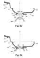
- FIG. 3a shows the patient interface 100 schematically in a cross-sectional drawing together with the indicated patient's eye 900 in the withdrawn state
- FIG. 3b shows patient interface 100 and eye 900 in the coupled state.
- the suction ring 150 comprises in coaxial arrangement a suction ring inner wall 151 b and a suction ring outer wall 151 a, which are adapted in shape to the curvature of the eye 900.
- a suction ring inner wall 151 b and a suction ring outer wall 151 a which are adapted in shape to the curvature of the eye 900.
- FIG. 3b can be seen, forming suction ring outer wall 151 a and the suction ring inner wall 151 b together an annular hollow chamber 152, the end faces of which rest on the cornea 905 and in which the suction nozzle 158 opens.
- FIG. 3b shown state can be evacuated by means of suction port 158, the hollow chamber 152 and placed in negative pressure, whereby the patient interface 100 is rigidly coupled to the eye 900.
- the patient's eye 900 in particular a part of the cornea 905, projects into the suction ring interior 154 delimited by the suction ring inner wall 151b
- the first source-side patient interface coupler 130 includes two spring arms 131 and a release button 132, which is designed as a hand-operated handle structure (see also FIGS FIG. 1 ).
- FIGS. 4a . 4b . 4c . 4d and 4e taken.
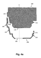
- the FIGS. 4a . 4b and 4c illustrate in a schematic representation of the coupling or assembly of the first separate (see FIG. 4a ) Intermediate element 200 to the application head 300.
- the first application head coupler Pin 310
- the first source-side intermediate element coupler bore 210
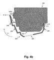
- the intermediate element 200 is inclined relative to the application head 300 or tilted.
- the intermediate element 200 is tilted or pivoted relative to the application head 300 in the direction indicated by arrow A (see FIG. 4b ), wherein the coupling formed by the engagement of the pins 310 in the holes 210 remains.
- the edge 240a of the spring lever 240 comes into contact with the interaction surface 340a of paragraph 340.
- the spring lever 240 resiliently outwardly, ie away from the application head 300, pressed and slides in the movement via the interaction surface 340a.
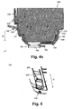
- FIG. 5 shows in a schematic isometric view of the outside view of a portion of the intermediate element 200 with spring latch 240th
- a later separation of the intermediate element 200 from the application head 300 can be done simply by the spring latch 240 spring-outward, d. H. away from the application head 300 in the direction B, whereby the engagement of spring latch 240 and latching surface 340b is released.
- the spring latch 240 and the shoulder 340 are designed so that the spring latch 240 in the end position according to Figure 4c is not completely relaxed, but on the inside (opposite direction B) exerts a spring force on the application head 300, whereby a defined and play-free fit of the intermediate member 200 is ensured on the application head 300.
- the entire intermediate element 200 in the assembled state of Fig. 3b slightly stretched elastically.
- the outer contour of the application head 300 and the inner contour of the concave shape of the intermediate element 200 form a substantially backlash-free sliding pair.
- the housing of the application head 300 thus abuts against the inner wall of the intermediate element 200 essentially without play. Due to the preferably existing elasticity of the intermediate element 200, the housing of the application head 300 in the relaxed starting state can also have a slight excess over the inner contour of the intermediate element 200.
- FIGS. 4c . 4d . 4e Furthermore, the assembly respectively coupling of the patient interface 100 to the intermediate element 200 respectively to the application head 300 is shown. It shows Figure 4c the patient interface in the position withdrawn from the intermediate element 200 and the application head 300.
- the patient interface 100 may already be coupled via the suction ring 150 to the patient's eye 900, as previously with reference to FIGS FIGS. 3a, 3b was explained. Alternatively, however, the patient interface 100 may be mounted in isolation.
- the assembly of the patient interface 100 to the intermediate element 200 is carried out in basically the same way as the mounting of the intermediate element 200 to the application head 300 and is therefore shown in a correspondingly concise manner.
- the first source-side patient interface coupler (bore 120) is first coupled to the first patient-side intermediate element coupler (pin 220), thus restricting the freedom of movement of the patient interface 100 with respect to intermediate element 200 and application head 300.
- the first patient-side interelement coupler 220 is designed as a pin 220; as well as the first source-side intermediate element coupler 210, the first source-side patient interface coupler is designed as a bore 120. Due to the smaller compared to the intermediate element 200 dimensions of the patient interface 100 is exemplarily a single pin 220 and a single bore 120 in z. B. central arrangement provided. The state after mounting the pin 220 (first patient-side interposer coupler) in bore 120 (first source-side patient interface coupler) is in the FIG. 4d arge provides.
- the Required relative movement in practice is not preferred primarily by movement of the patient interface 100, but by movement of the application head 300 with intermediate element 200, wherein the patient interface 100 is supported and held, for example, by means of its handle structure. That is, in deviation of the schematic representation in FIG.
- the patient interface 100 has a patient interface interior 153 (see FIG FIG. 3a ), which tapers conically towards the patient's eye 900, for example by the fact that the interior 153 defined by the inner suction ring wall 151 b narrows increasingly in the direction of the patient's eye 900 in the applied state.
- the interior of the patient interface 153 is provided to receive (correspondingly removably) a correspondingly conical transparent contact body (instead of the liquid).
- the contact body has a flat surface on the source side to the application head 300 and the laser exit window 330 toward (eg normal to the optical axis running).
- the contact body can be coupled to the application head 300 on the source side (eg to a flat laser exit window).
- the contact body is planed on its (rejuvenated) side facing the eye 900 and thereby applanates the eye 900 or the cornea 905 in the applied state.
- Various patient interface 100 may also be provided, one for applanating with a contact body, the other for receiving fluid.
- materials for the contact body rigid, elastic or gel-like materials can be used.
- the patient interface 100 is tilted or pivoted relative to the application head 300 and the intermediate element 200 in the direction indicated by arrow A, wherein the engagement of pin 220 and holes 120 remains.
- the patient interface 100 may be held, and instead the application head 300 may be tilted with the intermediate member 200.
- the resilient pawl 130 locks as a second source-side patient interface coupler with the counter pawl 230 (see also FIG. 5 ) as a second patient-side intermediate element coupler, as in Figure 4e is shown.
- the counter-pawl 230 cooperates with the resilient pawl 130 in the same way as the spring pawl 240 with the paragraph 340, it being understood that the specific concretely used embodiment is irrelevant to the function and represent only embodiments accordingly.
- a later separation of the patient interface 100 from the intermediate element 200 can be effected simply by pressing the unlocking button 132 in the direction C, i. H. away from the application head 300. As a result, the engagement of spring latch 130 and counter pawl 230 is released.
- the intermediate element 200 and the patient interface 100 are embodied in one piece in each case in one piece and produced by injection molding from plastic, for example from a polycarbonate.
- the patient interface is at least partially elastic and is resiliently tensioned when coupling the second source-side patient interface coupler 130 to the second patient interface coupler 230.
Abstract
Ein Patienteninterface (100) zur Kopplung eines ophthalmologischen Applikationskopfes (300) an ein Patientenauge (900) umfasst eine patientenseitige Interface-Struktur (150) zur Kopplung an das Patientenauge (900) und eine quellseitige Interfacestruktur, um das Patienteninterface (100) starr an den Applikationskopf (300) oder an ein Zwischenelement (200) zu koppeln. Die quellseitige Interfacestruktur umfasst einen ersten quellseitigen Patienteninterfacekoppler (120) und einen zweiten quellseitigen Patienteninterfacekoppler (130). Der erste quellseitige Patienteninterfacekoppler (120) ist dazu ausgelegt, durch Herstellen einer Kopplung mit einem ersten Patienteninterfacekoppler-Gegenstück (220) des Applikationskopfes (300) oder des Zwischenelements (200) die Beweglichkeit des Patienteninterface (100) bezüglich des Applikationskopfes (300) oder des Zwischenelements (200) einzuschränken. Der zweite quellseitige Patienteninterfacekoppler (130 ist dazu ausgelegt, durch Herstellen einer Kopplung mit einem zweiten Patienteninterfacekoppler-Gegenstück (230) des Applikationskopfes (300) oder des Zwischenelements (200) das Patienteninterface (100) bei bestehender Kopplung des ersten quellseitigen Patienteninterfacekopplers (120) mit dem ersten Patienteninterfacekoppler-Gegenstück (220) starr an den Applikationskopf (300) oder das Zwischenelement (200) zu koppeln.A patient interface (100) for coupling an ophthalmic application head (300) to a patient's eye (900) comprises a patient-side interface structure (150) for coupling to the patient's eye (900) and a source-side interface structure to rigidly attach the patient interface (100) to the patient interface (100) Application head (300) or to an intermediate element (200) to couple. The source-side interface structure includes a first source-side patient interface coupler (120) and a second source-side patient interface coupler (130). The first source-side patient interface coupler (120) is adapted to provide, by establishing a coupling with a first patient interface coupler counterpart (220) of the application head (300) or the intermediate element (200), the mobility of the patient interface (100) with respect to the application head (300) or Restrict intermediate element (200). The second source-side patient interface coupler (130) is configured to interface with the patient interface (100) by interfacing with a second patient interface coupler counterpart (230) of the application head (300) or intermediate member (200) when the first source-side patient interface coupler (120) is coupled the first patient interface coupler counterpart (220) rigidly coupled to the application head (300) or the intermediate element (200).
Description
Die vorliegende Erfindung betrifft ein Patienteninterface zur Kopplung eines ophthalmologischen Applikationskopfes zur Anwendung von optischer Strahlung einer Strahlquelle an ein Patientenauge sowie ein Zwischenelement zur Anordnung zwischen einem Patienteninterface und dem ophthalmologischen Applikationskopf. Die Erfindung betrifft ferner einen zur Verwendung in Verbindung mit einem Patienteninterface ausgelegten ophthalmologischen Applikationskopf zur Anwendung von optischer Strahlung einer Strahlquelle. Die Erfindung betrifft weiterhin ein Verfahren zur Kopplung des ophthalmologischen Applikationskopfes an ein Patientenauge.The present invention relates to a patient interface for coupling an ophthalmic application head for the application of optical radiation of a beam source to a patient's eye and an intermediate element for the arrangement between a patient interface and the ophthalmological application head. The invention further relates to an ophthalmic application head designed for use in conjunction with a patient interface for the application of optical radiation of a beam source. The invention further relates to a method for coupling the ophthalmological application head to a patient's eye.
Zur Behandlung und/oder Diagnose von Augengewebe ist der Einsatz von Lasern bekannt. Entsprechende Vorrichtungen weisen beispielsweise ein Basisgerät mit einer Laser-Lichtquelle zur Erzeugung von Laserpulsen, beispielsweise Femtosekundenlaserpulse, sowie einen Applikationskopf mit einem Projektionsobjektiv auf, der zur Behandlung mit dem Patientenauge gekoppelt wird. Der Applikationskopf kann, beispielsweise über einen Gelenkarm, beweglich mit dem Basisgerät verbunden sein, wobei der Gelenkarm zugleich der optischen Strahlführung von der Laser-Lichtquelle zum Applikationskopf dienen kann. Eine entsprechende Anordnung ist beispielsweise in der
Die mechanische und optische Kopplung des Applikationskopfes an das Patientenauge, beispielsweise an die Hornhaut und/oder Sklera des Patientenauges, erfolgt über ein Patienteninterface, wobei das Patienteninterface einen transparenten Kontaktkörper umfassen kann, durch welchen die aus dem Projektionsobjektiv austretenden Laserpulse geleitet werden und der durch mechanischen Kontakt mit der Hornhaut diese bezüglich des Patienteninterface und des Projektionsobjektives fixiert. Alternativ zur Kopplung mittels eines Kontaktkörpers kann eine Flüssigkeitskopplung vorgesehen werden, wobei sich zwischen Hornhaut und Projektionsobjektiv eine Koppelflüssigkeit, beispielsweise physiologische Kochsalzlösung befindet. Entsprechende Patienteninterfaces sind beispielsweise aus
Für Patienteninterfaces, die bei ophthalmologische Laseranwendungen eingesetzt werden, ergeben sich eine Reihe von Anforderungen und Randbedingungen, welche die Übertragung zahlreicher aus anderen Anwendungsgebieten bekannten Konstruktionen verunmöglichen bzw. als aus praktischer Sicht impraktikabel erscheinen lassen. Wesentliche Beschränkungen ergeben sich aus der bestehenden Nähe der Vorrichtungen zum Patientenauge und insbesondere dem direkten physischen Kontakt des Patienteninterface mit dem Patientenauge. Neben hohen Sicherheitsanforderungen ergibt sich hieraus, dass zumindest das Patienteninterface leicht handhabbar und sicher zu befestigen ausgestaltet ist.For patient interfaces that are used in ophthalmic laser applications, there are a number of requirements and boundary conditions, which make the transmission of numerous constructions known from other fields of application impossible or impracticable from a practical point of view. Significant limitations result from the proximity of the devices to the patient's eye and, in particular, the direct physical contact of the patient interface with the patient's eye. In addition to high safety requirements, this results in that at least the patient interface is designed to be easy to handle and secure.
Obgleich die Platzverhältnisse in der Umgebung des Einsatzortes am Patientenauge eng und gedrängt sind, sollte das Patientenauge für den Benutzer während der Behandlung zugänglich und sichtbar sein. Patienteninterface und übrige Komponenten sollten daher die Zugänglichkeit und Sicht möglichst gering beeinträchtigen.Although the space around the site of use is close and crowded on the patient's eye, the patient's eye should be accessible and visible to the user during treatment. The patient interface and other components should therefore minimize the accessibility and visibility.
Aufgrund der erheblichen medizinischen Risiken bei einer Fehlleitung des Laserstrahls, die zu unerwünschter Beeinträchtigung und gar Zerstörung von Augengewebe führen kann, sind Komponenten, die im Bereich des Strahlengangs vom Lichtprojektor zum Patientenauge angeordnet werden, korrekt zu positionieren und auszurichten sowie sicher miteinander zu koppeln bzw. zu verbinden.Due to the considerable medical risks associated with misdirection of the laser beam, which can lead to undesired impairment and even destruction of eye tissue, components which are in the area of the beam path from the light projector to the patient's eye be positioned correctly, align and safely coupled with each other or connect.
Es ist eine Aufgabe der vorliegenden Erfindung, Vorrichtungen, insbesondere ein Patienteninterface, für ophthalmologische Laseranwendungen sowie mit diesem Patienteninterface interagierende Vorrichtungen bereitzustellen, welche zumindest einige Nachteile des Stands der Technik nicht aufweisen. Es ist insbesondere eine Aufgabe der vorliegenden Erfindung, ein Patienteninterface, ein Zwischenelement und einen Applikationskopf zur ophthalmologischen Anwendung von optischer Strahlung einer Strahlquelle vorzuschlagen, welche wenigstens gewisse der eingehend erläuterten Anforderungen an die Kopplung eines Patienteninterface an einen Applikationskopf hinsichtlich einfacher und sicherer Verbindung ganz oder teilweise erfüllen.It is an object of the present invention to provide devices, particularly a patient interface, for ophthalmic laser applications as well as devices interacting with this patient interface which do not have at least some disadvantages of the prior art. It is a particular object of the present invention, a patient interface, an intermediate element and an application head for ophthalmic application of optical radiation of a beam source to propose at least some of the detailed requirements for the coupling of a patient interface to an application head in terms of simple and secure connection in whole or in part fulfill.
Gemäss der vorliegenden Erfindung werden diese Ziele durch die Merkmale der unabhängigen Ansprüche erreicht. Weitere vorteilhafte Ausführungsformen gehen ausserdem aus den abhängigen Ansprüchen und der Beschreibung hervor.According to the present invention, these objects are achieved by the features of the independent claims. Further advantageous embodiments are also evident from the dependent claims and the description.
Ein Patienteninterface zur Kopplung eines ophthalmologischen Applikationskopfes zur Anwendung von optischer Strahlung einer Strahlquelle an ein Patientenauge umfasst:
- eine patientenseitige Interfacestruktur, die zur Kopplung an das Patientenauge ausgestaltet ist, und
- eine quellseitige Interfacestruktur, welche dazu ausgelegt ist, das Patienteninterface starr an den Applikationskopf oder an ein zur Anordnung zwischen Applikationskopf und Patienteninterface vorgesehenes Zwischenelement zu koppeln.
- a patient-side interface structure, which is designed for coupling to the patient's eye, and
- a source-side interface structure, which is designed to rigidly couple the patient interface to the application head or to an intermediate element provided for placement between the application head and the patient interface.
Die oben genannten Ziele werden durch die vorliegende Erfindung insbesondere dadurch erreicht, dass die quellseitige Interfacestruktur einen ersten quellseitigen Patienteninterfacekoppler und einen zusätzlichen zweiten quellseitigen Patienteninterfacekoppler umfasst. Der erste quellseitige Patienteninterfacekoppler ist dazu ausgelegt, durch Herstellen einer Kopplung mit einem ersten Patienteninterfacekoppler-Gegenstück des Applikationskopfes oder des Zwischenelements die Beweglichkeit des Patienteninterface bezüglich des Applikationskopfes oder des Zwischenelements einzuschränken. Der zweite quellseitige Patienteninterfacekoppler ist dazu ausgelegt, durch Herstellen einer Kopplung mit einem zweiten Patienteninterfacekoppler-Gegenstück des Applikationskopfes oder des Zwischenelements das Patienteninterface bei bestehender Kopplung des ersten quellseitigen Patienteninterfacekopplers mit dem ersten Patienteninterfacekoppler-Gegenstück starr an den Applikationskopf oder das Zwischenelement zu koppeln. Der erste quellseitige Patienteninterfacekoppler weist somit den Vorteil auf, dass er dazu ausgelegt, die Beweglichkeit des Patienteninterface bezüglich des Applikationskopfes oder des Zwischenelements durch Herstellen einer Kopplung mit dem ersten Patienteninterfacekoppler-Gegenstück des Applikationskopfes oder des Zwischenelements einzuschränken, bevor eine Kopplung des zweiten quellseitigen Patienteninterfacekopplers mit einem zweiten Patienteninterfacekoppler-Gegenstück des Applikationskopfes oder des Zwischenelements vorgenommen wird, das heisst ohne dass für die Einschränkung der Beweglichkeit des Patienteninterface bezüglich des Applikationskopfes oder des Zwischenelements eine Kopplung des zweiten quellseitigen Patienteninterfacekopplers mit dem zweiten Patienteninterfacekoppler-Gegenstück des Applikationskopfes oder des Zwischenelements erforderlich ist.The above-mentioned objects are achieved by the present invention in particular in that the source-side interface structure comprises a first source-side patient interface coupler and an additional second source-side patient interface coupler. The first source-side patient interface coupler is adapted to restrict the mobility of the patient interface with respect to the application head or the intermediate element by establishing a coupling with a first patient interface coupler counterpart of the application head or the intermediate element. The second source-side patient interface coupler is configured to rigidly couple the patient interface to the application head or the intermediate member by coupling to a second patient interface coupler counterpart of the application head or intermediate member upon coupling the first source-side patient interface coupler to the first patient interface-coupler counterpart. The first source-side patient interface coupler thus has the advantage that it is designed to limit the mobility of the patient interface with respect to the application head or the intermediate member by establishing a coupling with the first patient interface coupler counterpart of the application head or the intermediate member before coupling the second source-side patient interface coupler a second patient interface coupler counterpart of the application head or the intermediate element is made, that is, without the coupling of the second source-side interface coupler with the second patient interface coupler counterpart of the application head or the intermediate element is required for limiting the mobility of the patient interface with respect to the application head or the intermediate element.
Die Begriffe "quellseitig" und "patientenseitig" in Bezug auf ein Element bezeichnen, dass das Element in der betriebsgemässen Ausrichtung dem Applikationskopf bzw. dem Patientenauge zugewandt und im betriebsgemässen Zustand direkt oder indirekt mit diesem verbunden ist.The terms "source side" and "patient side" in relation to an element denote that the element in the operational orientation of the application head or the patient's eye facing and operatively connected directly or indirectly with this.
Eine Einschränkung der Beweglichkeit bedeutet, dass die Zahl der mechanischen Freiheitsgrade zur Bewegung reduziert wird, aber zumindest ein Freiheitsgrad weiterhin vorhanden ist. Eine starre Kopplung bedeutet die Aufhebung sämtlicher Freiheitsgrade, wodurch sich die starr gekoppelten Elemente im Wesentlichen wie ein gemeinsamer Körper verhalten.Restricting mobility means reducing the number of mechanical degrees of freedom for movement, but at least one degree of freedom still exists. A rigid coupling means the cancellation of all degrees of freedom, whereby the rigidly coupled elements behave essentially as a common body.
In einer Ausführungsvariante sind genau zwei Kopplungen bzw. Koppelstellen vorgesehen, welche so angeordnet sind, dass bei korrekt erstellter erster und zweiter Kopplung keine Relativbewegungen des Patienteninterface gegenüber dem Applikationskopf respektive dem Zwischenelement möglich sind, das Patienteninterface jedoch seine Position und/oder Orientierung gegenüber dem Applikationskopf oder dem Zwischenelement ändert, wenn mindesten eine der Kopplungen nicht mehr korrekt gegeben ist, beispielsweise dadurch, dass das Patienteninterface schwerkraftbedingt vom Applikationskopf bzw. dem ggf. vorhandenen Zwischenelement abfällt und in einer Variante mit entsprechender Ausgestaltung in der veränderten Position den Eintritt des Laserstrahls in das Patientenauge blockiert. Dem gegenüber birgt eine Kopplung von Patienteninterface und Applikationskopf oder Zwischenelement über eine grössere Zahl von drei und mehr Koppelpunkten die Gefahr, dass sich beispielsweise eine von drei Kopplungen während des Betriebs löst, wobei die verbleibenden Kopplungen das Patienteninterface weiterhin am Applikationskopf oder dem Zwischenelement halten, aber nicht mehr hinreichend starr fixieren, so dass Relativbewegungen möglich werden, ohne dass dies vom Benutzer bemerkt wird und/oder der Eintritt des Laserstrahls in das Patientenauge verhindert wird. Dabei ist anzumerken, dass die visuelle Überprüfung einer Kopplung insbesondere bei mehr als zwei Kopplungspunkten schwer bis gar nicht möglich ist, wenn sich das Patienteninterface am Auge befindet.In one embodiment, exactly two couplings or coupling points are provided, which are arranged so that with correctly created first and second coupling no relative movements of the patient interface relative to the application head or the intermediate element are possible, the patient interface, however, its position and / or orientation relative to the application head or the intermediate element changes when at least one of the couplings is no longer given correctly, for example, by the fact that the patient interface due to gravity drops from the application head or the intermediate element if present and in a variant with a corresponding configuration in the changed position, the entry of the laser beam in the Patient eye blocked. On the other hand, a coupling of the patient interface and the application head or intermediate element over a larger number of three or more crosspoints entails the risk that, for example, one of three couplings will be released during operation, with the remaining couplings continuing to hold the patient interface at the application head or intermediate element, but no longer sufficiently rigid fix, so that relative movements are possible without this being noticed by the user and / or the entry of the laser beam is prevented in the patient's eye. It should be noted that the visual verification of a coupling especially in more than two coupling points is difficult if not impossible if the patient interface is on the eye.
Im montieren Zustand des Patienteninterface ermöglicht eine starre Kopplung mit dem Applikationskopf oder dem gegebenenfalls vorhanden Zwischenelement eine korrekte Ausrichtung der Laserpulse auf einen Zielpunkt oder ein Zielgebiet im Patientenauge.In the assembled state of the patient interface, a rigid coupling with the application head or the intermediate element that may be present enables correct alignment of the laser pulses with a target point or target area in the patient's eye.
Der erste und der zweite quellseitige Patienteninterfacekoppler sind bevorzugt an einander gegenüberliegenden Seiten oder Wandungen des Patienteninterface angeordnet.The first and second source-side patient interface couplers are preferably disposed on opposite sides or walls of the patient interface.
Das Patienteninterface gibt somit für die Montage an den Applikationskopf oder das ggf. vorhandene Zwischenelement das folgende Vorgehen vor: Ausgehend von einem ungekoppelten Ausgangszustand in dem das Patienteninterface nicht mit dem Applikationskopf bzw. dem ggf. vorhandenen Zwischenelement gekoppelt und von diesem separat ist, wird zunächst eine erste Kopplung durch Herstellung einer Kopplung des ersten quellseitigen Patienteninterfacekopplers mit dem ersten Patienteninterfacekoppler-Gegenstück herbeigeführt. Unter Beibehaltung dieser ersten Kopplung (und nur dann) kann das Patienteninterface durch eine Bewegung, z. B. durch eine Kipp- oder Schwenkbewegung bezüglich des Applikationskopfes bzw. des vorhandenen Zwischenelements bewegt werden, bis durch Herstellung einer Kopplung des zweiten quellseitigen Patienteninterfacekopplers mit dem zweiten Patienteninterfacekoppler-Gegenstück zusätzlich eine zweite Kopplung hergestellt ist.The patient interface thus specifies the following procedure for mounting on the application head or the intermediate element that may be present: Starting from an uncoupled initial state in which the patient interface is not coupled to the application head or the intermediate element present and is separate therefrom, first a first coupling is effected by establishing a coupling of the first source side patient interface coupler to the first patient interface coupler counterpart. While maintaining this first coupling (and only then), the patient interface can be moved by a movement, e.g. B. be moved by a tilting or pivoting movement relative to the application head or the existing intermediate element until additionally a second coupling is made by establishing a coupling of the second source-side patient interface coupler with the second patient interface coupler counterpart.
Vorteilhaft sind das Patienteninterface sowie der Applikationskopf bzw. das ggf. vorhandene Zwischenelement derart gestaltet, dass die zur Herstellung der zweiten Kopplung erforderliche Bewegung des Patienteninterface mit einer (einzigen) Hand möglich ist.Advantageously, the patient interface as well as the application head or the possibly existing intermediate element are designed such that the movement of the patient interface required for producing the second coupling with a (single) hand is possible.
Der erste und der zweite quellseitige Interface-Koppler sind für eine lösbare Kopplung, insbesondere eine zerstörungsfrei lösbare Kopplung, mit den jeweiligen Gegenstücken ausgelegt. Wie weiter unten dargestellt wird, können die Koppler für ein einfaches Lösen mit wenigen Handmanipulationen bei einhändiger Bedienung ausgestaltet werden.The first and the second source-side interface coupler are designed for a detachable coupling, in particular a nondestructive detachable coupling, with the respective counterparts. As will be seen below, the couplers can be designed for easy release with a few hand manipulations in one-handed operation.
Die einhändige Erstellung und Lösung der Kopplung des Patienteninterface mit dem Applikationskopf bzw. dem Zwischenelement ist insbesondere von Vorteil beim Einsatz von ophthalmologischen Lasersystemen, bei denen der Applikationskopf an einem Schwenkarm befestigt ist und mit der Hand gehalten respektive geführt wird. Dem Benutzer wird so ermöglicht, den Applikationskopf mit der einen Hand zu halten und mit der anderen die Kopplung mit respektive Loslösung von dem Patienteninterface und einem ggf. vorhandenen Zwischenelement mit wenigen einfachen Handgriffen vorzunehmen.The one-handed creation and solution of the coupling of the patient interface with the application head or the intermediate element is particularly advantageous in the use of ophthalmic laser systems, in which the application head is attached to a pivot arm and held by hand or guided. The user is thus enabled to hold the application head with one hand and make with the other the coupling with respectively detachment from the patient interface and any intermediate element with a few simple steps.
Das Patienteninterface ist vorteilhaft als Einweg-Produkt zur einmaligen Anwendung bei einer Augenbehandlung und anschliessender Entsorgung ausgeführt. Das Patienteninterface kann als einfaches oder Mehrkomponenten- Spritzgussteil aus Kunststoff ausgeführt sein. Zusätzlich oder alternativ können weitere Materialien wie Metall und/oder weitere Fertigungsverfahren, wie Tiefziehen oder spanende Bearbeitung oder 3D-Drucktechnik eingesetzt werden.The patient interface is advantageously designed as a disposable product for single use in an eye treatment and subsequent disposal. The patient interface can be designed as a simple or multi-component plastic injection molded part. Additionally or alternatively, other materials such as metal and / or other manufacturing processes such as deep drawing or machining or 3D printing technology can be used.
Das Patienteninterface kann schalenartig ausgebildet sein und zum Applikationskopf bzw. Zwischenelement hin im Wesentlichen eine konkave und zum Patienten hin im Wesentlichen eine konvexe Formgebung aufweisen, wobei die konkave Formgebung komplementär zu einer entsprechenden konvexen Formgebung des Applikationskopfes oder Zwischenelementes sein kann.The patient interface may be of a shell-like design and may have a concave shape towards the application head or intermediate element and a convex shape towards the patient, wherein the concave shape may be complementary to a corresponding convex shape of the application head or intermediate element.
In einer beispielhaften Ausführungsform ist der erste quellseitige Patienteninterfacekoppler dazu ausgelegt ist, unter Beibehaltung mindestens eines Freiheitsgrades mit dem ersten Patienteninterfacekoppler-Gegenstück formschlüssig zu koppeln. Der Formschluss kann durch eine näherungsweise punktartige Kopplung erfolgen. So kann der erste quellseitige Patienteninterfacekoppler als Ausschnitt, Bohrung, Sackloch oder generell ein konkaves Element, z. B. eine Mulde, in einer Wandung des Patienteninterface ausgebildet sein. Das korrespondierende erste Patienteninterfacekoppler-Gegenstück kann in diesem Fall als konvexes Element, beispielsweise als Stift oder Noppen, an einer Wandung des Applikationskopfes oder Zwischenelementes vorgesehen sein. Die Anordnung ist derart, dass beim Ansetzen des Patienteninterface an den Applikationskopf oder das Zwischenelement das konvexe Element und das konkave Element bzw. die Bohrung oder der Ausschnitt in Eingriff gelangen und dadurch eine formschlüssige Verbindung bilden. Alternativ oder zusätzlich kann die Kopplung beispielsweise magnetisch oder durch Vakuum erfolgen. Ferner kann ein konvexes Element am Patienteninterface und ein korrespondierendes konkaves Element, ein Ausschnitt oder ein Bohrung am Applikationskopf oder Zwischenelement angeordnet sein. Je nach Gestalt, Abmessungen und Gewicht des Patienteninterface können der erste quellseitige Patienteninterfacekoppler und der korrespondierende erste Gegenkoppler jeweils auch durch mehrere Einzelelemente realisiert werden, beispielsweise zwei oder mehr Stifte oder Noppen und eine entsprechende Anzahl konkaver Elemente, Bohrungen oder Ausschnitte. Die Einzelelemente sind dabei vorteilhafterweise so anzuordnen, dass sie konstruktionsbedingt gleichzeitig eine Kopplung herstellen bzw. auflösen. Zu jedem Zeitpunkt sind damit entweder alle den ersten quellseitigen Patienteninterfacekoppler und den korrespondierenden ersten Gegenkoppler bildenden Elementpaare jeweils gemeinsam entweder im gekoppelten oder ungekoppelten Zustand.In an exemplary embodiment, the first source-side patient interface coupler is configured to positively couple with the first patient interface coupler counterpart while maintaining at least one degree of freedom. The positive connection can be made by an approximately point-like coupling. Thus, the first source-side patient interface coupler as a cutout, bore, blind hole or generally a concave element, for. B. a trough, be formed in a wall of the patient interface. The corresponding first patient interface coupler counterpart can be provided in this case as a convex element, for example as a pin or nubs, on a wall of the application head or intermediate element. The arrangement is such that upon application of the patient interface to the application head or the intermediate element, the convex element and the concave element or the bore or the cutout engage and thereby form a positive connection. Alternatively or additionally, the coupling can be done, for example, magnetically or by vacuum. Furthermore, a convex element can be arranged on the patient interface and a corresponding concave element, a cutout or a bore on the application head or intermediate element. Depending on the shape, dimensions and weight of the patient interface, the first source-side patient interface coupler and the corresponding first counter-coupler can each be realized by a plurality of individual elements, for example, two or more pins or knobs and a corresponding number of concave elements, holes or cutouts. The individual elements are advantageously to be arranged so that they simultaneously produce a coupling or dissolve by design. At any time, either all of the first source-side patient interface coupler and the corresponding first counter-coupler-forming element pairs are thus either together in the coupled or uncoupled state.
In einer beispielhaften Ausführungsform ist der erste quellseitige Patienteninterfacekoppler dazu ausgelegt, durch Herstellen einer Kopplung mit dem ersten Patienteninterfacekoppler-Gegenstück eine Zwangsführung für das Patienteninterface bezüglich des Applikationskopfes oder des Zwischenelements herzustellen. Die Zwangsführung kann das Patienteninterface bezüglich des Applikationskopfes oder des Zwischenelementes soweit festlegen, dass für das Patienteninterface bei vorhandener Kopplung des ersten quellseitigen Patienteninterfacekopplers und des ersten Interface-Gegenkopplers nur eine Bewegung, beispielsweise eine Kipp- oder Schwenkbewegung, in eine Richtung möglich ist, die zur Herstellung einer Kopplung des zweiten quellseitigen Patienteninterfaces mit dem zweiten Patienteninterfacekoppler-Gegenstück führt. Eine derartige Zwangsführung kann dadurch realisiert werden, dass Innenwandungen der konkaven Form des Patienteninterface nach Herstellung der Kopplung zwischen dem ersten quellseitigen Patienteninterfacekoppler und dem ersten Interface-Gegenkoppler im Wesentlichen spielfrei an korrespondierende Aussenwandungen des Applikationskopfes anliegen und für diese eine Gleitführung bilden.In an exemplary embodiment, the first source-side patient interface coupler is configured to provide positive feedback for the patient interface with respect to the application head or the intermediate member by establishing a coupling with the first patient interface coupler counterpart. The restraint can set the patient interface with respect to the application head or the intermediate element to the extent that only a movement, such as a tilting or pivoting movement, in a direction is possible for the patient interface with existing coupling of the first source side and the first interface Gegenkopplers Producing a coupling of the second source-side patient interface with the second patient interface coupler counterpart results. Such positive guidance can be realized in that inner walls of the concave shape of the patient interface after production of the coupling between the first source-side patient interface coupler and the first interface counter-coupler substantially free of play abut against corresponding outer walls of the application head and form a sliding guide for this.
In einer beispielhaften Ausführungsform erfordert das Herstellen einer Kopplung des zweiten quellseitigen Patienteninterfacekopplers mit dem zweiten Patienteninterfacekoppler-Gegenstück, dass der erste quellseitige Patienteninterfacekoppler mit dem ersten Patienteninterfacekoppler-Gegenstück gekoppelt ist. Eine derartige Ausführungsform stellt sicher, dass eine Montage des Patienteninterface nur in der vorgesehenen und korrekten Weise möglich ist und im montierten Zustand das Patienteninterface bezüglich des Applikationskopfes oder des Zwischenelementes korrekt positioniert und orientiert ist. Vorteilhaft muss vom Benutzer nur der zweite Interfacekoppler überprüft werden.In an exemplary embodiment, coupling the second source side patient interface coupler to the second patient interface coupler counterpart requires the first source side patient interface coupler to be coupled to the first patient interface coupler counterpart. Such an embodiment ensures that an assembly of the patient interface is possible only in the intended and correct manner and in the assembled state, the patient interface with respect to the application head or the intermediate element is correctly positioned and oriented. Advantageously, only the second interface coupler has to be checked by the user.
In einer beispielhaften Ausführungsform ist der zweite quellseitige Patienteninterfacekoppler dazu ausgelegt, mit dem zweiten Patienteninterfacekoppler-Gegenstück mittels Schnapp- oder Rastverbindung zu koppeln. Hierzu kann das Patienteninterface als erster quellseitiger Patienteninterfacekoppler eine federnde Klinke und das erste Patienteninterfacekoppler-Gegenstück eine korrespondierende Gegenklinke aufweisen. Die Federklinke und die Gegenklinke können dabei derart angeordnet sein, dass sie in einer Endstellung des Patienteninterface relativ zum Applikationskopf oder Zwischenelement zwangsläufig in Eingriff geraten und so das Patienteninterface mit dem Applikationskopf oder dem Zwischenelement verriegeln oder verrasten. Die Bewegungs-Endposition des Patienteninterface entspricht dabei der Position und Orientierung des Patienteninterface relativ zum Applikationskopf oder Zwischenelement im betriebsbereiten Zustand. In einer beispielhaften Anordnung umfasst der zweite quellseitige Patienteninterfacekoppler dabei einen einhändig lösbaren Schnapphebel, beispielsweise eine Federklinke. Dieser kann federnd gestaltet sein und an seinem Ende eine Klinke zum Verrasten mit der Gegenklinke aufweisen. Ein einhändiges Lösen kann mittels einer Entriegelungstaste vorgesehen werden, welche Teil des Schnapphebels ist und mit welcher sich durch federndes Biegen der Klinke der Eingriff von Klinke und Gegenklinke aufheben lässt, beispielsweise mittels Finger-oder Daumendruck. Wird der zweite quellseitige Patienteninterfacekoppler, beispielsweise aus Steifigkeitsgründen, durch eine Kombination mehrerer einzelner Schnapphebel realisiert, können diese strukturell verbunden sein, um ein gemeinsames Aufheben des Schnapp- oder Rasteingriffs mit der Gegenklinke und damit ein Aufheben der Kopplung zu ermöglichen.In an exemplary embodiment, the second source-side patient interface coupler is configured to communicate with the second patient interface coupler counterpart Pair snap or snap connection. For this purpose, the patient interface as the first source-side patient interface coupler may have a resilient pawl and the first patient interface coupler counterpart may have a corresponding counter pawl. The spring latch and the counter pawl can be arranged such that they inevitably come into engagement in an end position of the patient interface relative to the application head or intermediate element and thus lock or lock the patient interface with the application head or the intermediate element. The movement end position of the patient interface corresponds to the position and orientation of the patient interface relative to the application head or intermediate element in the ready state. In an exemplary arrangement, the second source-side patient interface coupler comprises a one-handed releasable snap lever, for example a spring latch. This may be resilient and have at its end a latch for locking with the counter pawl. One-handed release can be provided by means of a release button, which is part of the snap lever and with which can be picked up by resilient bending of the pawl engagement of pawl and pawl, for example by means of finger or thumb pressure. If the second source-side patient interface coupler is realized, for example for rigidity reasons, by a combination of a plurality of individual snap-action levers, these may be structurally connected in order to enable the snap-action or detent engagement with the counter-pawl to be canceled together, and thus the coupling to be released.
In einer alternativen Ausführungsform können die Anordnung von Federklinke und Gegenklinke vertauscht werden. In weiteren Ausführungsformen werden statt zusammenwirkenden Klinken eine Anordnung aus konvexen Elementen am Patienteninterface, beispielsweise Noppen, und korrespondierenden konkaven Elementen, Ausschnitten oder Bohrungen am Applikationskopf oder Zwischenelement verwendet, oder umgekehrt. Schnapp- und Rastverbindungen sind insoweit besonders günstig, als das vollendete Herstellen der Kopplung, also das Einrasten oder Einschnappen, aufgrund der hierbei auftretenden Kraftdiskontinuität gut taktil feststellbar und ferner mit einem charakteristischen Schnapp- oder Klackgeräusch verbunden ist, was eine zusätzliche akustische Rückmeldung an den Benutzer darstellt.In an alternative embodiment, the arrangement of spring latch and counter pawl can be reversed. In further embodiments, an arrangement of convex elements on the patient interface, such as knobs, and corresponding concave elements, cutouts or holes on the application head or intermediate element are used instead of cooperating pawls, or vice versa. Snap and snap connections are particularly advantageous insofar as the completed production of the coupling, so the snapping or snapping, due to the force discontinuity occurring here tactile detectable and also connected to a characteristic snap or click noise, resulting in additional acoustic feedback to the user represents.
Grundsätzlich können der zweite quellseitige Patienteninterfacekoppler und der korrespondierende zweite Gegenkoppler auch durch zwei oder mehr Paare von konstruktiven Einzelelementen realisiert werden. Dabei kann die Zahl der Einzelelemente für den ersten und den zweiten quellseitigen Patienteninterfacekoppler gleich oder verschieden sein. So sind beispielsweise Ausführungen möglich, in denen der erste quellseitige Patienteninterfacekoppler durch zwei Bohrungen gebildet werden, die zur Kopplung mit zwei korrespondierenden Stiften als erstem Gegenkoppler in Eingriff gelangen, während der zweite quellseitige Patienteninterfacekoppler durch eine einzelne, zu den Bohrungen symmetrisch angeordnete Federklinke gebildet wird.In principle, the second source-side patient interface coupler and the corresponding second counter-coupler can also be realized by two or more pairs of structural individual elements. The number of individual elements for the first and the second source-side patient interface coupler can be the same or different. For example, embodiments are possible in which the first source-side patient interface coupler are formed by two holes which engage for coupling with two corresponding pins as a first counter-coupler, while the second source-side patient interface coupler is formed by a single, to the holes symmetrically arranged spring latch.
In einer beispielhaften Ausführungsform ist das Patienteninterface mindestens teilweise elastisch. Beim Herstellen der Kopplung des zweiten quellseitigen Patienteninterfacekopplers mit dem zweiten Patienteninterfacekoppler-Gegenstück wird das Patienteninterface federnd gespannt. Eine federnde Spannung des Patienteninterface gewährleistet einen straffen und spielfreien Sitz des Patienteninterface auf dem Applikationskopf oder dem Zwischenelement unter Gewährleistung der korrekten Position und Orientierung. Eine mindestens teilweise Elastizität des Patienteninterface kann durch geeignete Formgebung des Patienteninterface sowie die Materialauswahl, beispielsweise bei Herstellung im Spritzgussverfahren, erfolgen. Bei einer solchen Ausgestaltung weist das Patienteninterface insgesamt die erforderliche Elastizität auf. Alternativ können auch spezielle federnde Elemente, z. B. Federn eingesetzt werden. Ferner kann eine Elastizität durch den ersten und/oder den zweiten quellseitigen Patienteninterfacekoppler realisiert werden. Hierzu werden diese so ausgelegt, dass sie im gekoppeltem Zustand, also bei bestehendem Eingriff mit dem korrespondierenden Gegenkoppler, unter Vorspannung stehen.In an exemplary embodiment, the patient interface is at least partially elastic. When establishing the coupling of the second source-side patient interface coupler with the second patient interface coupler counterpart, the patient interface is resiliently tensioned. A resilient tension of the patient interface ensures a tight and play-free fit of the patient interface on the application head or the intermediate element while ensuring the correct position and orientation. An at least partial elasticity of the patient interface can be achieved by suitable shaping of the patient interface as well as the choice of material, for example when produced by injection molding. In such an embodiment, the patient interface overall has the required elasticity. Alternatively, special resilient elements, such. B. springs are used. Furthermore, an elasticity by the first and / or the second source-side patient interface coupler can be realized. For this purpose, they are designed so that they are under bias in the coupled state, ie in existing engagement with the corresponding counter-coupler.
In einer beispielhaften Ausführungsform erfordert das Herstellen der Kopplung des ersten quellseitigen Patienteninterfacekopplers mit dem ersten Patienteninterfacekoppler-Gegenstück, dass der zweite quellseitige Patienteninterfacekoppler mit dem zweiten Patienteninterfacekoppler-Gegenstück nicht gekoppelt ist. Eine derartige Ausgestaltung stellt entsprechend sicher, dass - entsprechend der vorgesehenen Montagereihenfolge für eine korrekte Platzierung des Patienteninterface - immer zuerst die Verbindung des ersten quellseitigen Patienteninterfacekopplers mit seinem korrespondieren Gegenstück erfolgt und erst anschliessend die Verbindung des zweiten quellseitigen Patienteninterfacekopplers. Dieses Ziel lässt sich durch geeignete Anordnung vom ersten und zweiten quellseitigen Patienteninterfacekoppler sowie geeignete Ausgestaltung dieser Koppler erzielen, wie nachfolgend anhand von Ausführungsbeispielen dargestellt wird.In an exemplary embodiment, establishing the coupling of the first source side patient interface coupler to the first patient interface coupler counterpart requires that the second source side patient interface coupler is not coupled to the second patient interface coupler counterpart. Such a configuration accordingly ensures that - according to the intended mounting sequence for a correct placement of the patient interface - always first the connection of the first source-side patient interface coupler with its corresponding counterpart takes place and only then the connection of the second source-side patient interface coupler. This goal can be achieved by suitable arrangement of the first and second source-side patient interface coupler and suitable design of this coupler, as will be illustrated below with reference to embodiments.
In einer beispielhaften Ausführungsform umfasst das Patienteninterface ein mit einer Hand haltbare Griffstruktur. In einer möglichen Ausführung ist diese Griffstruktur integral mit dem zweiten quellseitigen Patienteninterfacekoppler. Eine mit der Hand haltbare Griffstruktur ist günstig zur Feinpositionierung und Ausrichtung des Patienteninterface vor bzw. bei der Kopplung mit dem Applikationskopf oder dem Zwischenelement. Eine Griffstruktur erscheint insbesondere dann vorteilhaft, wenn - entsprechend einer möglichen Anwendung des Patienteninterface - zunächst das Patienteninterface an das Patientenauge gekoppelt wird und anschliessend die Verbindung mit dem Applikationskopf erfolgt. Zur Integration in den zweiten quellseitige Patienteninterfacekoppler kann ein federnder Schnapphebel, beispielsweise wie oben erläutert eine Entriegelungstaste eines Schnapphebels, als Griffstruktur ausgebildet sein.In an exemplary embodiment, the patient interface comprises a hand-holdable handle structure. In one possible embodiment, this handle structure is integral with the second source-side patient interface coupler. A hand-held handle structure is favorable for fine positioning and alignment of the patient interface before or during the coupling with the application head or the intermediate element. A handle structure appears to be particularly advantageous if - according to a possible application of the patient interface - first the patient interface is coupled to the patient's eye and then the connection with the application head takes place. For integration into the second source-side patient interface coupler, a resilient snap-action lever, for example, as explained above, an unlocking button of a snap-action lever, can be designed as a handle structure.
In einer beispielhaften Ausführungsform umfasst die patientenseitige Interfacestruktur einen Saugring, welcher zum Herstellen einer starren Vakuumkopplung mit dem Patientenauge vorgesehen ist. Der Saugring ist zum Aufsetzen auf die Hornhaut des Patientenauges vorgesehen und kann eine doppelwandige Struktur mit einer inneren und einer zu dieser koaxialen und äquidistanten äusseren Wandung aufweisen, wobei der Freiraum zwischen der inneren Wandung und der äusseren Wandung als eine zum Patientenauge hin offene ringförmige Hohlkammer zur Ausbildung eines Unterdrucks oder Vakuums ausgestaltet ist. Hierzu kann der Saugring einen mit dem Zwischenraum fluidisch gekoppelten Anschluss, beispielsweise einen Stutzen, für die Verbindung mit einer Unterdruck-oder Vakuumpumpe aufweisen. Bei einer derartigen Anordnung verläuft der Laserstrahl bei der Anwendung durch den von der inneren Wandung umgebenen Freiraum.In an exemplary embodiment, the patient-side interface structure comprises a suction ring, which is provided for producing a rigid vacuum coupling with the patient's eye. The suction ring is intended to be placed on the cornea of the patient's eye and may have a double-walled structure with an inner and a coaxial and equidistant outer wall, wherein the free space between the inner wall and the outer wall as an open towards the patient's eye annular hollow chamber Training a negative pressure or vacuum is configured. For this purpose, the suction ring may have a connection fluidically coupled to the intermediate space, for example a connecting piece, for connection to a vacuum or vacuum pump. In such an arrangement, the laser beam passes in the application by the free space surrounded by the inner wall.
In einer beispielhaften Ausgestaltung ist das Patienteninterface dafür ausgelegt, teilweise mit einer optischen Koppelflüssigkeit, beispielsweise physiologische Kochsalzlösung, gefüllt zu werden. Die einzufüllende Menge der Koppelflüssigkeit wird dabei so bemessen, dass ein, nach Kopplung des Patienteninterface an den Applikationskopf oder das Zwischenelement, zwischen dem Patientenauge und dem Applikationskopf oder dem Zwischenelement bestehender Freiraum vollständig flüssigkeitsgefüllt ist. Das Befüllen mit Koppelflüssigkeit erfolgt bevorzugt nach der Kopplung des Patienteninterface an das Patientenauge und vor der Kopplung des Patienteninterface an den Applikationskopf oder das Zwischenelement. Statt einer Flüssigkeitsfüllung kann die Kopplung des Applikationskopfes an das Patientenauge auch mittels eines auf das Patientenauge aufgesetzten Kontaktkörpers erfolgen. Der Kontaktkörper kann Teil des Applikationskopfes oder des Patienteninterfaces sein. Zusätzlich können noch Membranen und Folien als Sterilbarriere eingesetzt werden.In an exemplary embodiment, the patient interface is designed to be partially filled with an optical coupling fluid, for example physiological saline solution. The amount of coupling fluid to be filled is in this case dimensioned such that, after coupling the patient interface to the application head or the intermediate element, between the patient's eye and the application head or the intermediate element existing free space is completely filled with liquid. The filling with coupling fluid is preferably carried out after the coupling of the patient interface to the patient's eye and before the coupling of the patient interface to the application head or the intermediate element. Instead of a liquid filling, the coupling of the application head to the patient's eye can also take place by means of a contact body placed on the patient's eye. The contact body may be part of the application head or the patient interface. In addition, membranes and films can still be used as a sterile barrier.
Gemäss einem weiteren Aspekt wird ein Zwischenelement zur Anordnung zwischen einem Patienteninterface und einem ophthalmologischen Applikationskopf zur Anwendung von optischer Strahlung einer Strahlquelle bereitgestellt.According to a further aspect, an intermediate element is provided for the arrangement between a patient interface and an ophthalmic application head for the application of optical radiation of a beam source.
Das Zwischenelement ist zur Anordnung zwischen einem ophthalmologischen Applikationskopf zur Anwendung von optischer Strahlung einer Strahlquelle und einem offenbarungsgemässen Patienteninterface vorgesehen und umfasst:
- eine patientenseitige Zwischenelement-Interfacestruktur und
- eine quellseitige Zwischenelement-Interfacestruktur.
- a patient-side inter-element interface structure and
- a source-side inter-element interface structure.
Die patientenseitige Zwischenelement-Interfacestruktur umfasst einen ersten patientenseitigen Zwischenelementkoppler und einen zusätzlichen zweiten patientenseitigen Zwischenelementkoppler. Der erste patientenseitige Zwischenelementkoppler bildet dabei ein erstes Patienteninterfacekoppler-Gegenstück und der zweite patientenseitige Zwischenelementkoppler bildet ein zweites Patienteninterfacekoppler-Gegenstück.The patient-side interposer interface structure comprises a first patient-side interposer coupler and an additional second patient-side interposer coupler. The first patient-side intermediate element coupler forms a first patient interface coupler counterpart and the second patient-side intermediate element coupler forms a second patient interface coupler counterpart.
Der erste patientenseitige Zwischenelementkoppler ist dazu ausgelegt, durch Herstellen einer Kopplung mit dem ersten quellseitigen Patienteninterfacekoppler des Patienteninterface die Beweglichkeit des Patienteninterface bezüglich des Zwischenelements einzuschränken. Der zweite patientenseitige Zwischenelementkoppler ist dazu ausgelegt, durch Herstellen einer Kopplung mit dem zweiten quellseitigen Patienteninterfacekoppler des Patienteninterface bei bestehender Kopplung des ersten patientenseitigen Zwischenelementkopplers mit dem ersten quellseitigen Patienteninterfacekoppler das Patienteninterface starr an das Zwischenelement zu koppeln.The first patient-side intermediate element coupler is designed to limit the mobility of the patient interface with respect to the intermediate element by establishing a coupling with the first source-side patient interface coupler of the patient interface. The second patient-side intermediate element coupler is designed to rigidly couple the patient interface to the intermediate element by establishing a coupling with the second source-side patient interface coupler of the patient interface with existing coupling of the first patient-side intermediate element coupler to the first source-side patient interface coupler.
Das Zwischenelement ist zur Anordnung zwischen Patienteninterface und Applikationskopf vorgesehen, wobei sich im montierten Zustand eine Sandwich-Struktur ergibt. Das Zwischenelement kann - ebenso wie das Patienteninterface -schalenartig ausgebildet sein. Zum Applikationskopf hin weisst es dann eine im Wesentlichen konkave Formgebung auf, die komplementär zu einer im Wesentlichen konvexen Formgebung des Applikationskopfes ist. Zum Patienteninterface weisst ein solches Zwischenelement eine im Wesentlichen konvexe Formgebung auf, die komplementär zu einer im Wesentlichen konkaven Formgebung des Patienteninterface ist. In einer solchen Anordnung bedeckt oder umhüllt das Zwischenelement einen dem Patienten zugewandten Teil des Applikationskopfes wie eine Schutzhülle.The intermediate element is intended to be arranged between the patient interface and the application head, resulting in a sandwich structure in the mounted state. The Intermediate element can - like the patient interface -shell-like design. Towards the application head, it then has a substantially concave shape, which is complementary to a substantially convex shape of the application head. To the patient interface, such an intermediate element has a substantially convex shape that is complementary to a substantially concave shape of the patient interface. In such an arrangement, the intermediate element covers or envelopes a portion of the application head facing the patient like a protective cover.
Der erste und zweite patientenseitige Zwischenelementkoppler sind zur Interaktion mit dem ersten und zweiten quellseitigen Patienteninterfacekoppler des Patienteninterface ausgestaltet. Wenn der erste quellseitige Patienteninterfacekoppler etwa als konkaves Element, beispielsweise ein Pin, Stift oder Noppen, gebildet wird, ist der erste patientenseitige Patienteninterfacekoppler entsprechend als konvexes Element, beispielsweise in Form einer Mulde, einer Bohrung oder eines Ausschnitts, gebildet, und umgekehrt. Entsprechendes gilt für den zweiten patientenseitigen Zwischenelement-Koppler.The first and second patient-side interposer couplers are configured to interact with the first and second source-side patient interface couplers of the patient interface. If the first source-side patient interface coupler is formed approximately as a concave element, for example a pin, pin or nub, the first patient-side patient interface coupler is accordingly formed as a convex element, for example in the form of a trough, a bore or a cut-out, and vice versa. The same applies to the second patient-side intermediate element coupler.
Ein offenbarungsgemässes Zwischenelement kann einen optisch transparenten Trennkörper, beispielsweise in Form einer transparenten Folie aufweisen, der im montierten Zustand an das Austrittsfenster oder Projektionsobjektiv des Applikationskopfes anliegt.An intermediate element according to the disclosure can have an optically transparent separating body, for example in the form of a transparent foil, which in the mounted state rests against the exit window or projection objective of the application head.
Das optionale Zwischenelement trennt den Applikationskopf vom Patienteninterface und schützt den Applikationskopf beispielsweise vor Verschmutzungen. Wird entsprechend obiger Beschreibung eine optische Koppelflüssigkeit eingesetzt, schützt der optional vorhandene transparente Trennkörper, z.B. eine Folie oder Membran, ferner den Applikationskopf vor Kontakt mit der ggf. zusätzlich durch Keime und Gewebezellen verunreinigten Kontaktflüssigkeit. Alternativ kann das Zwischenelement auch einen Kontaktkörper beinhalten.The optional intermediate element separates the application head from the patient interface and protects the application head against soiling, for example. If, in accordance with the above description, an optical coupling fluid is used, the optionally present transparent separating body, eg a foil or membrane, further protects the application head from contact with the possibly additionally contaminated by germs and tissue cells Contact liquid. Alternatively, the intermediate element may also include a contact body.
In einer beispielhaften Ausführungsform ist die quellseitige Zwischenelement-Interfacestruktur dazu ausgelegt, das Zwischenelement starr an den Applikationskopf zu koppeln. Die quellseitige Zwischenelement-Interfacestruktur umfasst dabei einen ersten quellseitigen Zwischenelementkoppler und einen zweiten quellseitigen Zwischenelementkoppler. Der erste quellseitige Zwischenelementkoppler ist dazu ausgelegt, durch Herstellen einer Kopplung mit einem ersten Applikationskopfkoppler des Applikationskopfes die Beweglichkeit des Zwischenelements bezüglich des Applikationskopfes einzuschränken. Der zweite quellseitige Zwischenelementkoppler ist dazu ausgelegt, durch Kopplung mit einem zweiten Applikationskopfkoppler des Applikationskopfes bei bestehender Kopplung des ersten quellseitigen Zwischenelementkopplers mit dem ersten Applikationskopfkoppler das Zwischenelement starr an den Applikationskopf zu koppeln.In an exemplary embodiment, the source-side interface element interface structure is configured to rigidly couple the intermediate element to the application head. The source-side intermediate-element interface structure in this case comprises a first source-side intermediate element coupler and a second source-side intermediate element coupler. The first source-side intermediate element coupler is designed to limit the mobility of the intermediate element with respect to the application head by establishing a coupling with a first application head coupler of the application head. The second source-side intermediate element coupler is designed to couple the intermediate element rigidly to the application head by coupling with a second application head coupler of the application head when coupling the first source-side intermediate element coupler to the first application head coupler.
Bei einer derartigen Ausgestaltung des Zwischenelements wird das Zwischenelement in prinzipiell gleicher Weise an den Applikationskopf gekoppelt, wie das Patienteninterface an das Zwischenelement. Daher können für die Ausgestaltung des ersten und zweiten quellseitigen Zwischenelementkopplers die grundsätzlich gleichen Konstruktionen und Prinzipien angewandt werden, wie für den ersten und zweiten quellseitigen Patientenin-terfacekoppler. Für beispielhafte Ausgestaltungen wird daher auf die obigen Ausführungen verwiesen, wobei bezüglich der Kopplung mit dem Applikationskopf das Zwischenelement an die Stelle des Patienteninterface tritt.In such an embodiment of the intermediate element, the intermediate element is coupled to the application head in basically the same way as the patient interface to the intermediate element. Therefore, for the design of the first and second source-side Zwischenelementkopplers the basically same constructions and principles are applied as for the first and second source-side patient interface coupler. For exemplary embodiments, reference is therefore made to the above statements, wherein with respect to the coupling with the application head, the intermediate element takes the place of the patient interface.
In einem beispielhaften aber nicht zwingenden Einsatzverfahren wird das isolierte Patienteninterface an das Patientenauge gekoppelt, beispielsweise, wie oben beschrieben, mittels Vakuum. Anschliessend wird das Patienteninterface durch die im Betriebszustand dem Applikationskopf zugewandte konkave Seite des Patienteninterface wie eine Schale teilweise mit Koppelflüssigkeit befüllt, wobei die Koppelflüssigkeit direkt in Kontakt mit der Hornhaut des Patientenauges gelangt. Separat davon wird das Zwischenelement an den Applikationskopf gekoppelt bzw. montiert. In einem letzten Schritt erfolgt die Kopplung des mit dem Patientenauge gekoppelten Patienteninterface mit dem Zwischenelement.In an exemplary but non-mandatory deployment procedure, the isolated patient interface is coupled to the patient's eye, for example, as described above, by vacuum. Subsequently, the patient interface is replaced by the operating state the concave side of the patient interface facing the application head as a shell partially filled with coupling fluid, the coupling fluid comes directly into contact with the cornea of the patient's eye. Separately, the intermediate element is coupled or mounted on the application head. In a final step, the coupling of the patient interface coupled to the patient interface with the intermediate element takes place.
Der erste und/oder zweite quellseitige Zwischenelementkoppler und die korrespondierenden Gegenstücke des Applikationskopfes können, wie oben dargestellt, jeweils durch ein einzelnes Element oder durch zwei/oder mehrere Einzelelemente gebildet werden, wobei für die Anzahl und Anordnung die gleichen Überlegungen und Grundsätze gelten.The first and / or second source-side Zwischenelementkoppler and the corresponding counterparts of the application head can, as shown above, each formed by a single element or by two / or more individual elements, wherein the same considerations and principles apply to the number and arrangement.
Gemäss einem weiteren Aspekt wird ein zur Verwendung in Verbindung mit dem Patienteninterface ausgelegter ophthalmologischer Applikationskopf zur Anwendung von optischer Strahlung einer Strahlquelle bereitgestellt.According to a further aspect, an ophthalmic application head designed for use in conjunction with the patient interface is provided for applying optical radiation to a radiation source.
Der ophthalmologische Applikationskopf umfasst einen ersten Applikationskopfkoppler und einen zweiten Applikationskopfkoppler. Der erste Applikationskopfkoppler und der zweite Applikationskopfkoppler sind dabei als erstes Patienteninterfacekoppler-Gegenstück zur Kopplung mit einem ersten quellseitigen Patienteninterfacekoppler und als zweites Patienteninterfacekoppler-Gegenstück zur Kopplung mit einem zusätzlichen zweiten quellseitigen Patienteninterfacekoppler des Patienteninterface ausgelegt. Alternativ sind der erste Applikationskopfkoppler und der zweite Applikationskopfkoppler zur Kopplung mit einem ersten quellseitigen Zwischenelementkoppler und einem zweiten quellseitigen Zwischenelementkoppler eines Zwischenelements ausgelegt. Der erste und zweite Applikationskopfkoppler können in beispielhaften Ausführungsformen so gestaltet sein, wie oben im Zusammenhang der Kopplung des Patienteninterface oder Zwischenelementes an den Applikationskopf erläutert wurde.The ophthalmic application head comprises a first application head coupler and a second application head coupler. The first application head coupler and the second application head coupler are designed as the first patient interface coupler counterpart for coupling to a first source-side patient interface coupler and a second patient interface coupler counterpart for coupling with an additional second source-side patient interface coupler of the patient interface. Alternatively, the first application head coupler and the second application head coupler are designed for coupling to a first source-side intermediate element coupler and a second source-side intermediate element coupler of an intermediate element. The first and second application head couplers may be configured in exemplary embodiments be as explained above in connection with the coupling of the patient interface or intermediate element to the application head.
Gemäss einem weiteren Aspekt wird weiterhin ein Verfahren zur Kopplung eines ophthalmologischen Applikationskopfes zur Anwendung von optischer Strahlung einer Strahlquelle an ein Patientenauge bereitgestellt.According to a further aspect, a method is further provided for coupling an ophthalmic application head for the application of optical radiation of a beam source to a patient's eye.
Das Verfahren zur Kopplung des ophthalmologischen Applikationskopfes mittels eines Patienteninterface an ein Patientenauge umfasst die folgenden sequentiellen Schritte:
- Herstellen eines Kontaktes des Patienteninterface mit dem Applikationskopf oder einem zur Anordnung zwischen Applikationskopf und Patienteninterface vorgesehenen Zwischenelement,
- Einschränken der Beweglichkeit des Patienteninterface bezüglich des Applikationskopfes oder des Zwischenelements durch Herstellen einer ersten Kopplung zwischen Patienteninterface und Applikationskopf oder Zwischenelement,
- starres Koppeln des Patienteninterface an den Applikationskopf oder das Zwischenelement durch Herstellen einer zweiten Kopplung zwischen Patienteninterface und Applikationskopf unter Beibehaltung der ersten Kopplung.
- Producing a contact of the patient interface with the application head or an intermediate element provided for the arrangement between the application head and the patient interface,
- Restricting the mobility of the patient interface with respect to the application head or the intermediate element by establishing a first coupling between the patient interface and the application head or intermediate element,
- rigidly coupling the patient interface to the application head or the intermediate member by establishing a second coupling between the patient interface and the application head while maintaining the first coupling.
Das Verfahren kann ferner den Schritt der starren Kopplung eines Zwischenelementes and den Applikationskopf umfassen. Weitere optionale Verfahrensschritte ergeben sich unmittelbar aus der obigen Darstellung des Patienteninterface, Zwischenelements und Applikationskopfs, sowie nachfolgenden Ausführungsbeispielen.The method may further comprise the step of rigidly coupling an intermediate member to the application head. Further optional method steps result directly from the above representation of the patient interface, intermediate element and application head, as well as subsequent exemplary embodiments.
Insbesondere bilden das Patienteninterface und das Zwischenelement ein ophthalmologisches Schutzsystem zur Anwendung mit dem Applikationskopf, welches zur Ausführung des angeführten Verfahrens geeignet ist. Offenbarte Ausführungsformen von Patienteninterface, Zwischenelement und Applikationskopf offenbaren daher zugleich entsprechende Ausgestaltungen eines entsprechenden Schutzsystems und Verfahrens. In gleicher Weise offenbaren beschriebene beispielhafte Verfahrensschritte zugleich entsprechende Ausgestaltungen von Patienteninterface, Zwischenelement und Applikationskopf respektive von einem dadurch gebildeten Schutzsystem.In particular, the patient interface and the intermediate element form an ophthalmological protection system for use with the application head, which is suitable for carrying out the cited method. Disclosed Embodiments of Patient Interface, Intermediate element and application head therefore at the same time reveal corresponding embodiments of a corresponding protection system and method. In the same way described exemplary method steps reveal at the same time corresponding embodiments of the patient interface, intermediate element and application head, respectively, of a protection system formed thereby.
Nachfolgend wird eine Ausführung der vorliegenden Erfindung anhand eines Beispieles beschrieben. Das Beispiel der Ausführung wird durch die folgenden beigelegten Figuren illustriert:
- Figuren 1 und 2:
- zeigen einen Applikationskopf zur Anwendung von optischer Strahlung einer Strahlquelle zusammen mit einem Zwischenelement, einem Patienteninterface und einem Patientenauge.
- Figuren 3a und 3b:
- zeigen schematisch ein Patienteninterface im Querschnitt zusammen mit einem Patientenauge.
- Figuren 4a, 4b, 4c, 4d, 4e:
- verdeutlichen in schematischen Schnittdarstellungen die Kopplung eines Patienteninterface, eines Zwischenelements und Applikationskopfes.
- Figur 5:
- zeigt einen Ausschnitt eines Zwischenelementes.
- FIGS. 1 and 2:
- show an application head for the application of optical radiation of a beam source together with an intermediate element, a patient interface and a patient's eye.
- FIGS. 3a and 3b:
- schematically show a patient interface in cross section together with a patient's eye.
- FIGS. 4a, 4b, 4c, 4d, 4e:
- illustrate in schematic sectional views the coupling of a patient interface, an intermediate element and application head.
- FIG. 5:
- shows a section of an intermediate element.
Die
Der Applikationskopf 300 (zur Anwendung von optischer Strahlung einer Strahlquelle) hat ein Gehäuse mit einer im Wesentlichen konvexen Formgebung. An einer Stirnseite ragt von diesem der erste Applikationskopfkoppler ab, der beispielhaft durch zwei Pins 310 gebildet wird, wie in den
Das Zwischenelement 200 hat eine schalenförmige Formgebung und weist in der dem Applikationskopf 300 zugewandten Seite eine im Wesentlichen konkave Formgebung auf, korrespondierend zur Form des Gehäuses des Applikationskopfes 300. Im montierten Zustand ist das Zwischenelement 200 wie eine Hülle über einen dem Patienten zugewandten Teil des Applikationskopfes 300 bzw. dessen Gehäuse gestülpt und umgibt diesen spielfrei. Exemplarisch hat das Zwischenelement 200 ferner einen im montierten Zustand vom Applikationskopf 300 wegweisenden Handgriff 295, wie in den
Der zu den Pins 310 des ersten Applikationskopfkopplers korrespondierende erste quellseitige Zwischenelementkoppler ist beispielhaft durch zwei Bohrungen 210 realisiert, von denen in den
Das Patienteninterface 100 hat ebenso wie das Zwischenelement 200 eine schalenförmige Formgebung. Es weist an der dem Applikationskopf 300 und dem Zwischenelement 200 zugewandten Seite eine im Wesentlichen konkave Formgebung auf, korrespondierend zu der dem Patienten zugewandten konvexen Form des Zwischengehäuses 200. Im montierten Zustand ist das Patienteninterface 100 wie eine Hülle über einen dem Patienten zugewandten Teil des Zwischenelementes 200 gestülpt und starr mit diesem gekoppelt.The
Das Patienteninterface 100 umfasst einen Saugring 150 mit kreisförmigem Querschnitt, dessen äusserer Durchmesser so bemessen ist, dass er vollständig auf der Sklera platziert werden kann. Seitlich ragt vom Saugring 150 ein Saugstutzen 158 zur Verbindung mit einer (nicht dargestellten) Vakuumpumpe ab.The
Der erste quellseitige Patienteninterfacekoppler des Patienteninterface 100 wird beispielhaft durch eine Bohrung 120 in einer Wandung des Patienteninterface 100 gebildet, wie in den
Der zweite quellseitige Patienteninterfacekoppler des Patienteninterface 100 wird beispielhaft durch eine federnde Klinke 130 gebildet. Der korrespondierende zweite patientenseitige Zwischenelementkoppler wird aus einer zur Klinke 130 korrespondierenden Gegenklinke 230 als Vorsprung am Zwischenelement 200 gebildet, welche in den
An dieser Stelle soll festgehalten werden, dass durch das in
Nachfolgend wird spezifisch auf die
Der Saugring 150 umfasst in koaxialer Anordnung eine Saugring-Innenwand 151 b und eine Saugring-Aussenwand 151 a, die in ihrer Formgebung an die Wölbung des Auges 900 angepasst sind. Wie insbesondere aus
Der erste quellseitige Patienteninterfacekoppler 130 umfasst zwei Federarme 131 und eine Entriegelungstaste 132, welche als mit der Hand greibare Griffstruktur gestaltet ist (siehe auch
Nachfolgend wird explizit Bezug auf die
Anschliessend wird das Zwischenelement 200 bezüglich des Applikationskopfes 300 in der durch Pfeil A angedeuteten Richtung gekippt bzw. geschwenkt (siehe
Ein späteres Trennen des Zwischenelements 200 vom Applikationskopf 300 kann einfach dadurch erfolgen, dass die Federklinke 240 federnd nach aussen, d. h. vom Applikationskopf 300 weg in Richtung B, gezogen wird, wodurch der Eingriff von Federklinke 240 und Rastfläche 340b aufgehoben wird.A later separation of the
Vorteilhaft sind die Federklinke 240 und der Absatz 340 so ausgelegt, dass die Federklinke 240 in der Endposition gemäss
In den
Die Montage des Patienteninterface 100 an das Zwischenelement 200 erfolgt in grundsätzlich gleicher Weise wie die Montage des Zwischenelementes 200 an den Applikationskopf 300 und wird daher entsprechend knapp dargestellt.The assembly of the
Zur Montage werden zunächst der erste quellseitige Patienteninterfacekoppler (Bohrung 120) mit dem ersten patientenseitigen Zwischenelementkoppler (Pin 220) gekoppelt und so die Bewegungsfreiheit des Patienteninterface 100 bezüglich Zwischenelement 200 und Applikationskopf 300 eingeschränkt. Ebenso wie der erste Applikationskopfkoppler 310 ist der erste patientenseitige Zwischenelementkoppler 220 als Pin 220 ausgeführt; ebenso wie der erste quellseitige Zwischenelementkoppler 210 ist der erste quellseitige Patienteninterfacekoppler als Bohrung 120 ausgeführt. Aufgrund der im Vergleich zum Zwischenelement 200 geringeren Abmessungen des Patienteninterface 100 ist exemplarisch ein einziger Pin 220 und eine einzige Bohrung 120 in z. B. mittiger Anordnung vorgesehen. Der Zustand nach Einhängen des Pins 220 (erster patientenseitiger Zwischenelementkoppler) in Bohrung 120 (erster quellseitiger Patienteninterfacekoppler) ist in der
Insbesondere wenn das Patienteninterface 100 bereits an das Patientenauge 900 gekoppelt und der Innenraum des Patienteninterface 100 ggf. teilweise mit Koppelflüssigkeit gefüllt ist (die Flüssigkeitsinjektion erfolgt ggf. nach dem Ankoppeln des Patientenirlterface 100 an das Auge 900 und dem Koppeln an den Applikationskopf), erfolgt die erforderliche Relativbewegung in der Praxis bevorzugt nicht in erster Linie durch Bewegung des Patienteninterface 100, sondern durch Bewegung des Applikationskopfes 300 mit Zwischenelement 200, wobei das Patienteninterface 100 z.B. mittels seiner Griffstruktur unterstützt und gehalten wird. Das heisst, in Abweichung der schematischen Darstellung in
In einer Ausführungsvariante weist das Patienteninterface 100 einen Patienteninterface-Innenraum 153 auf (siehe
Anschliessend wird das Patienteninterface 100 bezüglich des Applikationskopfes 300 und des Zwischenelementes 200 in der durch Pfeil A angedeuteten Richtung gekippt bzw. geschwenkt, wobei der Eingriff von Pin 220 und Bohrungen 120 bestehen bleibt. Ebenso wie bei der vorherigen Bewegung kann das Patienteninterface 100 gehalten und stattdessen der Applikationskopf 300 mit dem Zwischenelement 200 gekippt bzw. geschwenkt werden.Subsequently, the
In der Endposition verrastet die federnde Klinke 130 als zweites quellseitiger Patienteninterfacekoppler mit der Gegenklinke 230 (siehe auch
Ein späteres Trennen des Patienteninterface 100 vom Zwischenelement 200 kann einfach dadurch erfolgen, dass die Entriegelungstaste 132 in Richtung C gedrückt wird, d. h. vom Applikationskopf 300 weg. Hierdurch wird der Eingriff von Federklinke 130 und Gegenklinke 230 aufgehoben.A later separation of the
Da die Montage bzw. Kopplung des Zwischenelementes 200 an den Applikationskopf 300 sowie die Montage bzw. Kopplung des Patienteninterface 100 an das Zwischenelement 200 auf analoge Weise und nach den gleichen Prinzipien erfolgen, ist ferner ersichtlich, das bei entsprechender konstruktiver Ausgestaltung von Patienteninterface 100 und Applikationskopf 300 auch eine direkte Kopplung dieser Elemente ohne das Zwischenelement 200 auf die gleiche Art und Weise möglich ist.Since the assembly or coupling of the
Das Zwischenelement 200 und das Patienteninterface 100 sind in einer Variante jeweils einstückig ausgeführt und in Spritzgusstechnik aus Kunststoff hergestellt, beispielsweise aus einem Polycarbonat. Das Patienteninterface ist mindestens teilweise elastisch ausgeführt und wird beim Koppeln des zweiten quellseitigen Patienteninterfacekopplers 130 mit dem zweiten Patienteninterfacekoppler-Gegenstück 230 federnd gespannt.The
- 100100
- Patienteninterfacepatient interface
- 120120
- Bohrung / erster quellseitiger PatienteninterfacekopplerBore / first source-side patient interface coupler
- 130130
- Federklinke / zweiter quellseitiger PatienteninterfacekopplerSpring latch / second source side patient interface coupler
- 131131
- Federarmspring arm
- 132132
- Entriegelungstasterelease
- 150150
- Saugringsuction ring
- 151a151a
- äussere Saugringwandouter suction ring wall
- 151b151b
- innere Saugringwandinner suction ring wall
- 152152
- Zwischenraumgap
- 153153
- Patienteninterface-InnenraumPatient Interface interior
- 154154
- Saugring-InnenraumSuction ring interior
- 158158
- Saugstutzensuction
- 200200
- Zwischenelementintermediate element
- 210210
- Bohrung / erster quellseitiger ZwischenelementkopplerBore / first source-side intermediate element coupler
- 220220
- Pin / erster patientenseitiger ZwischenelementkopplerPin / first patient-side intermediate element coupler
- 230230
- Gegenklinke / zweiter patientenseitiger ZwischenelementkopplerCounter pawl / second patient-side intermediate element coupler
- 240240
- Federklinke / zweiter quellseitiger ZwischenelementkopplerSpring latch / second source-side intermediate element coupler
- 240a240a
- RastflächeRest area
- 260260
- Laser-Durchgangsfenster / SchutzfolieLaser passage window / protective film
- 295295
- Handgriffhandle
- 300300
- Applikationskopf zur Anwendung von optischer Strahlung einer StrahlquelleApplication head for the application of optical radiation of a beam source
- 310310
- Pin / erster ApplikationskopfkopplerPin / first application head coupler
- 320320
- Sichtfensterwindow
- 330330
- Laser-AustrittsfensterLaser exit windows
- 340340
- Absatz / zweiter ApplikationskopfkopplerParagraph / second application head coupler
- 340a340a
- InteraktionsflächeInteraction surface
- 340b340b
- RastflächeRest area
- 900900
- Patientenaugepatient's eye
- 905905
- Hornhautcornea
Claims (15)
wobei der erste patientenseitige Zwischenelementkoppler (220) ein erstes Patienteninterfacekoppler-Gegenstück bildet und der zweite patientenseitige Zwischenelementkoppler (230) ein zweites Patienteninterfacekoppler-Gegenstück bildet, wobei der erste patientenseitige Zwischenelementkoppler (220) dazu ausgelegt ist, durch Herstellen einer Kopplung mit dem ersten quellseitigen Patienteninterfacekoppler (120) des Patienteninterface (100) die Beweglichkeit des Patienteninterface (100) bezüglich des Zwischenelements (200) einzuschränken,
und wobei der zweite patientenseitige Zwischenelementkoppler (230) dazu ausgelegt ist, durch Herstellen einer Kopplung mit dem zweiten quellseitigen Patienteninterfacekoppler (130) des Patienteninterface (100) bei bestehender Kopplung des ersten patientenseitigen Zwischenelementkopplers (220) mit dem ersten quellseitigen Patienteninterfacekoppler (120) das Patienteninterface (100) starr an das Zwischenelement (200) zu koppeln.An intermediate element (200) for placement between an ophthalmic application head (300) for using optical radiation from a beam source and a patient interface (100) according to any one of claims 1 to 11, the intermediate element (200) comprising:
wherein the first patient-side interposer coupler (220) forms a first patient interface coupler counterpart and the second patient-side interposer coupler (230) forms a second patient interface coupler counterpart, the first patient-side interposer coupler (220) being adapted to interface with the first source-side patient interface coupler (120) of the patient interface (100) to limit the mobility of the patient interface (100) with respect to the intermediate element (200),
and wherein the second patient-side interposer coupler (230) is adapted to connect the patient interface by coupling to the second source-side patient interface coupler (130) of the patient interface (100) when the first patient-side interposer coupler (220) is coupled to the first source-side patient interface coupler (120) (100) rigidly coupled to the intermediate element (200).
Applications Claiming Priority (1)
| Application Number | Priority Date | Filing Date | Title |
|---|---|---|---|
| CH01673/13A CH708619A1 (en) | 2013-09-26 | 2013-09-26 | Patient interface for ophthalmic optical therapeutic and diagnostic device. |
Publications (2)
| Publication Number | Publication Date |
|---|---|
| EP2853247A1 true EP2853247A1 (en) | 2015-04-01 |
| EP2853247B1 EP2853247B1 (en) | 2016-07-27 |
Family
ID=49322109
Family Applications (1)
| Application Number | Title | Priority Date | Filing Date |
|---|---|---|---|
| EP14003135.2A Active EP2853247B1 (en) | 2013-09-26 | 2014-09-10 | Patient inteface of ophthalmic and optic diagnosis and therapy device |
Country Status (4)
| Country | Link |
|---|---|
| US (1) | US9849037B2 (en) |
| EP (1) | EP2853247B1 (en) |
| CN (1) | CN104510563B (en) |
| CH (1) | CH708619A1 (en) |
Cited By (7)
| Publication number | Priority date | Publication date | Assignee | Title |
|---|---|---|---|---|
| EP3092986A2 (en) | 2015-05-11 | 2016-11-16 | Ziemer Ophthalmic Systems AG | Ophthalmological vacuum device and patient interface |
| EP3245989A1 (en) | 2016-05-17 | 2017-11-22 | Ziemer Ophthalmic Systems AG | Ophthalmological treatment apparatus |
| EP3260093A1 (en) | 2016-06-22 | 2017-12-27 | Ziemer Ophthalmic Systems AG | Ophthalmological patient interface |
| EP3323393A1 (en) | 2016-11-18 | 2018-05-23 | Ziemer Ophthalmic Systems AG | Ophthalmological patient interface |
| WO2019068866A1 (en) * | 2017-10-06 | 2019-04-11 | Schwind Eye-Tech-Solutions Gmbh | Patient interface system, method for coupling a patient interface with a patient interface holder, patient interface and patient interface holder |
| DE102020206420A1 (en) | 2020-05-24 | 2021-11-25 | Carl Zeiss Meditec Ag | UV laser based system for ametropia correction |
| EP4190286A1 (en) | 2021-12-06 | 2023-06-07 | Ziemer Ophthalmic Systems AG | Ophtalmological treatment and manufacture apparatus |
Families Citing this family (2)
| Publication number | Priority date | Publication date | Assignee | Title |
|---|---|---|---|---|
| EP3206643B1 (en) * | 2014-10-17 | 2021-08-25 | Carl Zeiss Meditec AG | Systems for short-pulse-laser eye surgery |
| US20200038241A1 (en) | 2018-08-02 | 2020-02-06 | Optimedica Corporation | Full depth laser ophthalmic surgical system, methods of calibrating the surgical system and treatment methods using the same |
Citations (5)
| Publication number | Priority date | Publication date | Assignee | Title |
|---|---|---|---|---|
| EP1731120A1 (en) | 2005-06-09 | 2006-12-13 | SIE AG, Surgical Instrument Engineering | Ophthalmological device for ablation of eye tissue. |
| US20080071254A1 (en) * | 2001-01-29 | 2008-03-20 | Advanced Medical Optics, Inc. | Ophthalmic interface apparatus and system and method of interfacing a surgical laser with an eye |
| US20080287927A1 (en) | 2004-12-02 | 2008-11-20 | Sie Ag Surgical Instrument Engineering | Protective device for ophthalmic laser treatment |
| WO2012031277A1 (en) | 2010-09-02 | 2012-03-08 | Optimedica Corporation | Patient interface for ophthalmologic diagnostic and interventional procedures |
| US20120283708A1 (en) | 2011-05-06 | 2012-11-08 | Ferenc Raksi | Adjusting ophthalmic docking system |
Family Cites Families (10)
| Publication number | Priority date | Publication date | Assignee | Title |
|---|---|---|---|---|
| CH655843A5 (en) * | 1981-04-02 | 1986-05-30 | Rodenstock Optik G | OPTICAL DEVICE FOR IMAGETING THE INSIDE OF THE EYE, ESPECIALLY DURING EYE SURGERY PROCEDURES. |
| US6863667B2 (en) * | 2001-01-29 | 2005-03-08 | Intralase Corp. | Ocular fixation and stabilization device for ophthalmic surgical applications |
| US7955324B2 (en) * | 2005-10-21 | 2011-06-07 | Technolas Perfect Vision Gmbh | Cornea contact system |
| US8632526B2 (en) * | 2007-11-07 | 2014-01-21 | Amo Development, Llc | System and method of interfacing a surgical laser with an eye |
| CN102625685B (en) * | 2009-07-24 | 2015-11-25 | 能斯雅有限公司 | For the liquid storage interface equipment of ophthalmology laser surgery |
| US8556425B2 (en) * | 2010-02-01 | 2013-10-15 | Lensar, Inc. | Purkinjie image-based alignment of suction ring in ophthalmic applications |
| US9237967B2 (en) * | 2011-10-21 | 2016-01-19 | Optimedica Corporation | Patient interface for ophthalmologic diagnostic and interventional procedures |
| EP2768397B1 (en) * | 2011-10-21 | 2022-11-09 | AMO Development, LLC | Patient interface for ophthalmologic diagnostic and interventional procedures |
| EP2633841B1 (en) * | 2012-02-28 | 2017-08-16 | Ziemer Ophthalmic Systems AG | Device for treating eye tissue using pulsed laser beams |
| US20130345682A1 (en) * | 2012-06-21 | 2013-12-26 | Markus Hailmann | Corneal Contact System |
-
2013
- 2013-09-26 CH CH01673/13A patent/CH708619A1/en not_active Application Discontinuation
-
2014
- 2014-09-10 EP EP14003135.2A patent/EP2853247B1/en active Active
- 2014-09-25 CN CN201410498315.3A patent/CN104510563B/en active Active
- 2014-09-26 US US14/498,461 patent/US9849037B2/en active Active
Patent Citations (5)
| Publication number | Priority date | Publication date | Assignee | Title |
|---|---|---|---|---|
| US20080071254A1 (en) * | 2001-01-29 | 2008-03-20 | Advanced Medical Optics, Inc. | Ophthalmic interface apparatus and system and method of interfacing a surgical laser with an eye |
| US20080287927A1 (en) | 2004-12-02 | 2008-11-20 | Sie Ag Surgical Instrument Engineering | Protective device for ophthalmic laser treatment |
| EP1731120A1 (en) | 2005-06-09 | 2006-12-13 | SIE AG, Surgical Instrument Engineering | Ophthalmological device for ablation of eye tissue. |
| WO2012031277A1 (en) | 2010-09-02 | 2012-03-08 | Optimedica Corporation | Patient interface for ophthalmologic diagnostic and interventional procedures |
| US20120283708A1 (en) | 2011-05-06 | 2012-11-08 | Ferenc Raksi | Adjusting ophthalmic docking system |
Cited By (12)
| Publication number | Priority date | Publication date | Assignee | Title |
|---|---|---|---|---|
| EP3092986A2 (en) | 2015-05-11 | 2016-11-16 | Ziemer Ophthalmic Systems AG | Ophthalmological vacuum device and patient interface |
| EP3245989A1 (en) | 2016-05-17 | 2017-11-22 | Ziemer Ophthalmic Systems AG | Ophthalmological treatment apparatus |
| WO2017198462A1 (en) | 2016-05-17 | 2017-11-23 | Ziemer Ophthalmic Systems Ag | Ophthalmological treatment apparatus |
| US11419764B2 (en) | 2016-05-17 | 2022-08-23 | Ziemer Ophthalmic Systems Ag | Ophthalmological treatment apparatus |
| EP3260093A1 (en) | 2016-06-22 | 2017-12-27 | Ziemer Ophthalmic Systems AG | Ophthalmological patient interface |
| US10413447B2 (en) | 2016-06-22 | 2019-09-17 | Ziemer Ophthalmic Systems Ag | Ophthalmological patient interface |
| EP3323393A1 (en) | 2016-11-18 | 2018-05-23 | Ziemer Ophthalmic Systems AG | Ophthalmological patient interface |
| WO2019068866A1 (en) * | 2017-10-06 | 2019-04-11 | Schwind Eye-Tech-Solutions Gmbh | Patient interface system, method for coupling a patient interface with a patient interface holder, patient interface and patient interface holder |
| DE102017123293A1 (en) | 2017-10-06 | 2019-04-11 | Schwind Eye-Tech-Solutions Gmbh | A patient interface system, method for coupling a patient interface to a patient interface holder, a patient interface, and a patient interface holder |
| US11865047B2 (en) | 2017-10-06 | 2024-01-09 | Schwind Eye-Tech-Solutions Gmbh | Patient interface system, method for coupling a patient interface with a patient interface holder, patient interface, and patient interface holder |
| DE102020206420A1 (en) | 2020-05-24 | 2021-11-25 | Carl Zeiss Meditec Ag | UV laser based system for ametropia correction |
| EP4190286A1 (en) | 2021-12-06 | 2023-06-07 | Ziemer Ophthalmic Systems AG | Ophtalmological treatment and manufacture apparatus |
Also Published As
| Publication number | Publication date |
|---|---|
| EP2853247B1 (en) | 2016-07-27 |
| US9849037B2 (en) | 2017-12-26 |
| CH708619A1 (en) | 2015-03-31 |
| CN104510563B (en) | 2017-08-11 |
| US20150088103A1 (en) | 2015-03-26 |
| CN104510563A (en) | 2015-04-15 |
Similar Documents
| Publication | Publication Date | Title |
|---|---|---|
| EP2853247B1 (en) | Patient inteface of ophthalmic and optic diagnosis and therapy device | |
| EP2292194B1 (en) | Adapter for mechanically coupling a laser processing device to an object | |
| EP2194410B1 (en) | Header device for an optical observation device | |
| WO2001037767A1 (en) | Device for improving the aqueous humour outflow in the eye of a living thing | |
| DE112017003642T5 (en) | Endoscope cap, endoscope and method of making an endoscope cap | |
| WO2002039892A1 (en) | Device and method for examining and/or treating an eye | |
| DE102014117407A1 (en) | Device for robotic surgery | |
| DE4024951B4 (en) | ophtalmoscope | |
| DE102011106802A1 (en) | REPLACEMENT AND HEAD-MOUNTED OPTICAL SYSTEM | |
| EP3678618B1 (en) | Liquid-patient interface | |
| DE102005040337A1 (en) | Contact lens for eye surgery, has lens body received in holder, where holder is formed such that vacuum channel between annular gap and eye is not closed with holohedral eye that is applied to lens front face of lens body | |
| DE102012018985B4 (en) | Drape for a surgical microscope | |
| WO2013167274A1 (en) | Attachment for a contact glass and production method for a contact glass system | |
| DE102018209194B4 (en) | Device for providing and inserting a graft or implant into a human or animal body and ready-to-use set comprising this device | |
| DE102014225635A1 (en) | Device and method for determining a relative geometric position of an eye | |
| DE102016206568A1 (en) | Treatment system for ophthalmological purposes with shelf | |
| DE60301121T2 (en) | Surgical tool holder | |
| WO2019068869A1 (en) | Patient interface system, camera system, method for coupling a patient interface with a patient interface holder, patient interface and patient interface holder | |
| DE4116810A1 (en) | Microscope equipment for surgical operations - has scissors linkage securing endoscope eyepiece in front of microscope | |
| WO2016091884A1 (en) | Device and method for fixing a relative geometric position of an eye | |
| DE112021000065T5 (en) | SYSTEM FOR ADMINISTRATION OF EYE DROPS | |
| DE4232280A1 (en) | Retina examination instrument with optical fibre illumination - has regulator on holder of ophthalmoscopic observation system for pressure on proximal light conductor end face on sclera | |
| EP0942695A1 (en) | Device for optically examining and/or treating the human eye | |
| DE2307809A1 (en) | EYE EXAMINATION DEVICE | |
| DE10105080A1 (en) | Lens insertion means comprise cylindrical r disc-shaped parts, hollow cylindrical or flanged parts, annular holder, and adjusting pincers or tongs. |
Legal Events
| Date | Code | Title | Description |
|---|---|---|---|
| PUAI | Public reference made under article 153(3) epc to a published international application that has entered the european phase |
Free format text: ORIGINAL CODE: 0009012 |
|
| 17P | Request for examination filed |
Effective date: 20140910 |
|
| AK | Designated contracting states |
Kind code of ref document: A1 Designated state(s): AL AT BE BG CH CY CZ DE DK EE ES FI FR GB GR HR HU IE IS IT LI LT LU LV MC MK MT NL NO PL PT RO RS SE SI SK SM TR |
|
| AX | Request for extension of the european patent |
Extension state: BA ME |
|
| R17P | Request for examination filed (corrected) |
Effective date: 20150625 |
|
| RBV | Designated contracting states (corrected) |
Designated state(s): AL AT BE BG CH CY CZ DE DK EE ES FI FR GB GR HR HU IE IS IT LI LT LU LV MC MK MT NL NO PL PT RO RS SE SI SK SM TR |
|
| GRAP | Despatch of communication of intention to grant a patent |
Free format text: ORIGINAL CODE: EPIDOSNIGR1 |
|
| INTG | Intention to grant announced |
Effective date: 20160426 |
|
| GRAS | Grant fee paid |
Free format text: ORIGINAL CODE: EPIDOSNIGR3 |
|
| GRAA | (expected) grant |
Free format text: ORIGINAL CODE: 0009210 |
|
| AK | Designated contracting states |
Kind code of ref document: B1 Designated state(s): AL AT BE BG CH CY CZ DE DK EE ES FI FR GB GR HR HU IE IS IT LI LT LU LV MC MK MT NL NO PL PT RO RS SE SI SK SM TR |
|
| REG | Reference to a national code |
Ref country code: GB Ref legal event code: FG4D Free format text: NOT ENGLISH |
|
| REG | Reference to a national code |
Ref country code: CH Ref legal event code: EP |
|
| REG | Reference to a national code |
Ref country code: AT Ref legal event code: REF Ref document number: 815182 Country of ref document: AT Kind code of ref document: T Effective date: 20160815 |
|
| REG | Reference to a national code |
Ref country code: IE Ref legal event code: FG4D Free format text: LANGUAGE OF EP DOCUMENT: GERMAN |
|
| REG | Reference to a national code |
Ref country code: DE Ref legal event code: R096 Ref document number: 502014001164 Country of ref document: DE |
|
| REG | Reference to a national code |
Ref country code: CH Ref legal event code: NV Representative=s name: RENTSCH PARTNER AG, CH |
|
| REG | Reference to a national code |
Ref country code: FR Ref legal event code: PLFP Year of fee payment: 3 |
|
| REG | Reference to a national code |
Ref country code: LT Ref legal event code: MG4D |
|
| REG | Reference to a national code |
Ref country code: NL Ref legal event code: MP Effective date: 20160727 |
|
| PG25 | Lapsed in a contracting state [announced via postgrant information from national office to epo] |
Ref country code: IT Free format text: LAPSE BECAUSE OF FAILURE TO SUBMIT A TRANSLATION OF THE DESCRIPTION OR TO PAY THE FEE WITHIN THE PRESCRIBED TIME-LIMIT Effective date: 20160727 Ref country code: NO Free format text: LAPSE BECAUSE OF FAILURE TO SUBMIT A TRANSLATION OF THE DESCRIPTION OR TO PAY THE FEE WITHIN THE PRESCRIBED TIME-LIMIT Effective date: 20161027 Ref country code: FI Free format text: LAPSE BECAUSE OF FAILURE TO SUBMIT A TRANSLATION OF THE DESCRIPTION OR TO PAY THE FEE WITHIN THE PRESCRIBED TIME-LIMIT Effective date: 20160727 Ref country code: NL Free format text: LAPSE BECAUSE OF FAILURE TO SUBMIT A TRANSLATION OF THE DESCRIPTION OR TO PAY THE FEE WITHIN THE PRESCRIBED TIME-LIMIT Effective date: 20160727 Ref country code: LT Free format text: LAPSE BECAUSE OF FAILURE TO SUBMIT A TRANSLATION OF THE DESCRIPTION OR TO PAY THE FEE WITHIN THE PRESCRIBED TIME-LIMIT Effective date: 20160727 Ref country code: HR Free format text: LAPSE BECAUSE OF FAILURE TO SUBMIT A TRANSLATION OF THE DESCRIPTION OR TO PAY THE FEE WITHIN THE PRESCRIBED TIME-LIMIT Effective date: 20160727 Ref country code: RS Free format text: LAPSE BECAUSE OF FAILURE TO SUBMIT A TRANSLATION OF THE DESCRIPTION OR TO PAY THE FEE WITHIN THE PRESCRIBED TIME-LIMIT Effective date: 20160727 Ref country code: IS Free format text: LAPSE BECAUSE OF FAILURE TO SUBMIT A TRANSLATION OF THE DESCRIPTION OR TO PAY THE FEE WITHIN THE PRESCRIBED TIME-LIMIT Effective date: 20161127 |
|
| PG25 | Lapsed in a contracting state [announced via postgrant information from national office to epo] |
Ref country code: BE Free format text: LAPSE BECAUSE OF NON-PAYMENT OF DUE FEES Effective date: 20160930 Ref country code: GR Free format text: LAPSE BECAUSE OF FAILURE TO SUBMIT A TRANSLATION OF THE DESCRIPTION OR TO PAY THE FEE WITHIN THE PRESCRIBED TIME-LIMIT Effective date: 20161028 Ref country code: ES Free format text: LAPSE BECAUSE OF FAILURE TO SUBMIT A TRANSLATION OF THE DESCRIPTION OR TO PAY THE FEE WITHIN THE PRESCRIBED TIME-LIMIT Effective date: 20160727 Ref country code: PL Free format text: LAPSE BECAUSE OF FAILURE TO SUBMIT A TRANSLATION OF THE DESCRIPTION OR TO PAY THE FEE WITHIN THE PRESCRIBED TIME-LIMIT Effective date: 20160727 Ref country code: LV Free format text: LAPSE BECAUSE OF FAILURE TO SUBMIT A TRANSLATION OF THE DESCRIPTION OR TO PAY THE FEE WITHIN THE PRESCRIBED TIME-LIMIT Effective date: 20160727 Ref country code: SE Free format text: LAPSE BECAUSE OF FAILURE TO SUBMIT A TRANSLATION OF THE DESCRIPTION OR TO PAY THE FEE WITHIN THE PRESCRIBED TIME-LIMIT Effective date: 20160727 Ref country code: PT Free format text: LAPSE BECAUSE OF FAILURE TO SUBMIT A TRANSLATION OF THE DESCRIPTION OR TO PAY THE FEE WITHIN THE PRESCRIBED TIME-LIMIT Effective date: 20161128 |
|
| PG25 | Lapsed in a contracting state [announced via postgrant information from national office to epo] |
Ref country code: MC Free format text: LAPSE BECAUSE OF FAILURE TO SUBMIT A TRANSLATION OF THE DESCRIPTION OR TO PAY THE FEE WITHIN THE PRESCRIBED TIME-LIMIT Effective date: 20160727 Ref country code: RO Free format text: LAPSE BECAUSE OF FAILURE TO SUBMIT A TRANSLATION OF THE DESCRIPTION OR TO PAY THE FEE WITHIN THE PRESCRIBED TIME-LIMIT Effective date: 20160727 Ref country code: EE Free format text: LAPSE BECAUSE OF FAILURE TO SUBMIT A TRANSLATION OF THE DESCRIPTION OR TO PAY THE FEE WITHIN THE PRESCRIBED TIME-LIMIT Effective date: 20160727 |
|
| REG | Reference to a national code |
Ref country code: DE Ref legal event code: R097 Ref document number: 502014001164 Country of ref document: DE |
|
| PG25 | Lapsed in a contracting state [announced via postgrant information from national office to epo] |
Ref country code: SK Free format text: LAPSE BECAUSE OF FAILURE TO SUBMIT A TRANSLATION OF THE DESCRIPTION OR TO PAY THE FEE WITHIN THE PRESCRIBED TIME-LIMIT Effective date: 20160727 Ref country code: DK Free format text: LAPSE BECAUSE OF FAILURE TO SUBMIT A TRANSLATION OF THE DESCRIPTION OR TO PAY THE FEE WITHIN THE PRESCRIBED TIME-LIMIT Effective date: 20160727 Ref country code: SM Free format text: LAPSE BECAUSE OF FAILURE TO SUBMIT A TRANSLATION OF THE DESCRIPTION OR TO PAY THE FEE WITHIN THE PRESCRIBED TIME-LIMIT Effective date: 20160727 Ref country code: CZ Free format text: LAPSE BECAUSE OF FAILURE TO SUBMIT A TRANSLATION OF THE DESCRIPTION OR TO PAY THE FEE WITHIN THE PRESCRIBED TIME-LIMIT Effective date: 20160727 Ref country code: BG Free format text: LAPSE BECAUSE OF FAILURE TO SUBMIT A TRANSLATION OF THE DESCRIPTION OR TO PAY THE FEE WITHIN THE PRESCRIBED TIME-LIMIT Effective date: 20161027 |
|
| PLBE | No opposition filed within time limit |
Free format text: ORIGINAL CODE: 0009261 |
|
| STAA | Information on the status of an ep patent application or granted ep patent |
Free format text: STATUS: NO OPPOSITION FILED WITHIN TIME LIMIT |
|
| REG | Reference to a national code |
Ref country code: IE Ref legal event code: MM4A |
|
| 26N | No opposition filed |
Effective date: 20170502 |
|
| PG25 | Lapsed in a contracting state [announced via postgrant information from national office to epo] |
Ref country code: IE Free format text: LAPSE BECAUSE OF NON-PAYMENT OF DUE FEES Effective date: 20160910 |
|
| PG25 | Lapsed in a contracting state [announced via postgrant information from national office to epo] |
Ref country code: SI Free format text: LAPSE BECAUSE OF FAILURE TO SUBMIT A TRANSLATION OF THE DESCRIPTION OR TO PAY THE FEE WITHIN THE PRESCRIBED TIME-LIMIT Effective date: 20160727 Ref country code: LU Free format text: LAPSE BECAUSE OF NON-PAYMENT OF DUE FEES Effective date: 20160910 |
|
| REG | Reference to a national code |
Ref country code: FR Ref legal event code: PLFP Year of fee payment: 4 |
|
| REG | Reference to a national code |
Ref country code: CH Ref legal event code: PCAR Free format text: NEW ADDRESS: BELLERIVESTRASSE 203 POSTFACH, 8034 ZUERICH (CH) |
|
| REG | Reference to a national code |
Ref country code: BE Ref legal event code: MM Effective date: 20160930 |
|
| PG25 | Lapsed in a contracting state [announced via postgrant information from national office to epo] |
Ref country code: HU Free format text: LAPSE BECAUSE OF FAILURE TO SUBMIT A TRANSLATION OF THE DESCRIPTION OR TO PAY THE FEE WITHIN THE PRESCRIBED TIME-LIMIT; INVALID AB INITIO Effective date: 20140910 |
|
| PG25 | Lapsed in a contracting state [announced via postgrant information from national office to epo] |
Ref country code: CY Free format text: LAPSE BECAUSE OF FAILURE TO SUBMIT A TRANSLATION OF THE DESCRIPTION OR TO PAY THE FEE WITHIN THE PRESCRIBED TIME-LIMIT Effective date: 20160727 Ref country code: MK Free format text: LAPSE BECAUSE OF FAILURE TO SUBMIT A TRANSLATION OF THE DESCRIPTION OR TO PAY THE FEE WITHIN THE PRESCRIBED TIME-LIMIT Effective date: 20160727 Ref country code: MT Free format text: LAPSE BECAUSE OF FAILURE TO SUBMIT A TRANSLATION OF THE DESCRIPTION OR TO PAY THE FEE WITHIN THE PRESCRIBED TIME-LIMIT Effective date: 20160727 |
|
| REG | Reference to a national code |
Ref country code: FR Ref legal event code: PLFP Year of fee payment: 5 |
|
| PG25 | Lapsed in a contracting state [announced via postgrant information from national office to epo] |
Ref country code: TR Free format text: LAPSE BECAUSE OF FAILURE TO SUBMIT A TRANSLATION OF THE DESCRIPTION OR TO PAY THE FEE WITHIN THE PRESCRIBED TIME-LIMIT Effective date: 20160727 Ref country code: AL Free format text: LAPSE BECAUSE OF FAILURE TO SUBMIT A TRANSLATION OF THE DESCRIPTION OR TO PAY THE FEE WITHIN THE PRESCRIBED TIME-LIMIT Effective date: 20160727 |
|
| REG | Reference to a national code |
Ref country code: AT Ref legal event code: MM01 Ref document number: 815182 Country of ref document: AT Kind code of ref document: T Effective date: 20190910 |
|
| PG25 | Lapsed in a contracting state [announced via postgrant information from national office to epo] |
Ref country code: AT Free format text: LAPSE BECAUSE OF NON-PAYMENT OF DUE FEES Effective date: 20190910 |
|
| P01 | Opt-out of the competence of the unified patent court (upc) registered |
Effective date: 20230513 |
|
| PGFP | Annual fee paid to national office [announced via postgrant information from national office to epo] |
Ref country code: GB Payment date: 20230920 Year of fee payment: 10 |
|
| PGFP | Annual fee paid to national office [announced via postgrant information from national office to epo] |
Ref country code: FR Payment date: 20230928 Year of fee payment: 10 Ref country code: DE Payment date: 20230920 Year of fee payment: 10 |
|
| PGFP | Annual fee paid to national office [announced via postgrant information from national office to epo] |
Ref country code: CH Payment date: 20231001 Year of fee payment: 10 |