EP2852963B1 - Röntgenröhre mit kohlenstoffverbundmaterial - Google Patents
Röntgenröhre mit kohlenstoffverbundmaterial Download PDFInfo
- Publication number
- EP2852963B1 EP2852963B1 EP13731166.8A EP13731166A EP2852963B1 EP 2852963 B1 EP2852963 B1 EP 2852963B1 EP 13731166 A EP13731166 A EP 13731166A EP 2852963 B1 EP2852963 B1 EP 2852963B1
- Authority
- EP
- European Patent Office
- Prior art keywords
- stator
- rotor
- magnetic field
- carbon
- anode
- Prior art date
- Legal status (The legal status is an assumption and is not a legal conclusion. Google has not performed a legal analysis and makes no representation as to the accuracy of the status listed.)
- Not-in-force
Links
- 239000000463 material Substances 0.000 title claims description 20
- OKTJSMMVPCPJKN-UHFFFAOYSA-N Carbon Chemical compound [C] OKTJSMMVPCPJKN-UHFFFAOYSA-N 0.000 title claims description 14
- 239000002131 composite material Substances 0.000 title claims description 14
- 229910052799 carbon Inorganic materials 0.000 title claims description 11
- 238000004804 winding Methods 0.000 claims description 27
- XEEYBQQBJWHFJM-UHFFFAOYSA-N Iron Chemical group [Fe] XEEYBQQBJWHFJM-UHFFFAOYSA-N 0.000 claims description 17
- 238000004590 computer program Methods 0.000 claims description 14
- 238000000034 method Methods 0.000 claims description 14
- 239000011203 carbon fibre reinforced carbon Substances 0.000 claims description 13
- 239000000835 fiber Substances 0.000 claims description 12
- 238000003384 imaging method Methods 0.000 claims description 7
- 230000001419 dependent effect Effects 0.000 claims description 5
- 238000010894 electron beam technology Methods 0.000 claims description 3
- 230000001939 inductive effect Effects 0.000 claims description 2
- 230000003993 interaction Effects 0.000 claims description 2
- 239000004020 conductor Substances 0.000 description 10
- RYGMFSIKBFXOCR-UHFFFAOYSA-N Copper Chemical compound [Cu] RYGMFSIKBFXOCR-UHFFFAOYSA-N 0.000 description 6
- 239000010949 copper Substances 0.000 description 6
- 229910052802 copper Inorganic materials 0.000 description 6
- 239000002041 carbon nanotube Substances 0.000 description 3
- 229910021393 carbon nanotube Inorganic materials 0.000 description 3
- 239000002071 nanotube Substances 0.000 description 3
- 230000001965 increasing effect Effects 0.000 description 2
- 230000006698 induction Effects 0.000 description 2
- 239000013585 weight reducing agent Substances 0.000 description 2
- 230000003936 working memory Effects 0.000 description 2
- FGUUSXIOTUKUDN-IBGZPJMESA-N C1(=CC=CC=C1)N1C2=C(NC([C@H](C1)NC=1OC(=NN=1)C1=CC=CC=C1)=O)C=CC=C2 Chemical compound C1(=CC=CC=C1)N1C2=C(NC([C@H](C1)NC=1OC(=NN=1)C1=CC=CC=C1)=O)C=CC=C2 FGUUSXIOTUKUDN-IBGZPJMESA-N 0.000 description 1
- 241000555745 Sciuridae Species 0.000 description 1
- RQMIWLMVTCKXAQ-UHFFFAOYSA-N [AlH3].[C] Chemical compound [AlH3].[C] RQMIWLMVTCKXAQ-UHFFFAOYSA-N 0.000 description 1
- 239000004411 aluminium Substances 0.000 description 1
- XAGFODPZIPBFFR-UHFFFAOYSA-N aluminium Chemical compound [Al] XAGFODPZIPBFFR-UHFFFAOYSA-N 0.000 description 1
- 229910052782 aluminium Inorganic materials 0.000 description 1
- 239000003575 carbonaceous material Substances 0.000 description 1
- 229910010293 ceramic material Inorganic materials 0.000 description 1
- 239000011248 coating agent Substances 0.000 description 1
- 238000000576 coating method Methods 0.000 description 1
- 238000002591 computed tomography Methods 0.000 description 1
- 230000006870 function Effects 0.000 description 1
- 230000010354 integration Effects 0.000 description 1
- 239000003562 lightweight material Substances 0.000 description 1
- 239000011159 matrix material Substances 0.000 description 1
- 239000000203 mixture Substances 0.000 description 1
- 239000002086 nanomaterial Substances 0.000 description 1
- 230000003287 optical effect Effects 0.000 description 1
- 230000005855 radiation Effects 0.000 description 1
- 239000011226 reinforced ceramic Substances 0.000 description 1
- 238000007789 sealing Methods 0.000 description 1
- 230000011218 segmentation Effects 0.000 description 1
- 239000007787 solid Substances 0.000 description 1
Images

Classifications
-
- H—ELECTRICITY
- H02—GENERATION; CONVERSION OR DISTRIBUTION OF ELECTRIC POWER
- H02K—DYNAMO-ELECTRIC MACHINES
- H02K3/00—Details of windings
- H02K3/02—Windings characterised by the conductor material
-
- H—ELECTRICITY
- H01—ELECTRIC ELEMENTS
- H01J—ELECTRIC DISCHARGE TUBES OR DISCHARGE LAMPS
- H01J35/00—X-ray tubes
- H01J35/02—Details
- H01J35/04—Electrodes ; Mutual position thereof; Constructional adaptations therefor
- H01J35/08—Anodes; Anti cathodes
- H01J35/10—Rotary anodes; Arrangements for rotating anodes; Cooling rotary anodes
- H01J35/101—Arrangements for rotating anodes, e.g. supporting means, means for greasing, means for sealing the axle or means for shielding or protecting the driving
- H01J35/1017—Bearings for rotating anodes
- H01J35/103—Magnetic bearings
-
- H—ELECTRICITY
- H01—ELECTRIC ELEMENTS
- H01J—ELECTRIC DISCHARGE TUBES OR DISCHARGE LAMPS
- H01J2235/00—X-ray tubes
- H01J2235/10—Drive means for anode (target) substrate
- H01J2235/1026—Means (motors) for driving the target (anode)
Definitions
- the present invention relates to a rotor for an X-ray tube, to an X-ray tube, to an X-ray imaging system, to a method for rotating an anode of an X-ray tube and to a computer program element as well as to a computer readable medium.
- a stator For driving a rotatable anode of an X-ray tube, a stator is provided which induces a voltage into a rotor coupled to the anode. Upon inducing a voltage into the rotor, for example made out of copper, a magnetic field is generated which interacts with the magnetic field of the stator.
- a voltage into the rotor for example made out of copper
- a magnetic field is generated which interacts with the magnetic field of the stator.
- the anode disc may thus be provided at least partially with lightweight material such as fibre reinforced ceramic material, as described, for example, in US 2011/0129068 A1 .
- DE 10 2008 025 702 A1 relates to a rotor and a stator, wherein the rotor comprises a plurality of rod-like elements that are connected in their end regions, wherein the winding of the rotor comprises at least partially a material comprising nanotubes.
- the nanotubes are carbon nanotubes.
- WO 2011/148978 A1 relates to a rotor of an induction motor, wherein the rotor includes a pair of ring-shaped conductors and a plurality of rod-shaped conductors that are connected between the pair of ring-shaped conductors and that form a cage-like shape together with a pair of ring-shaped conductors.
- the ring-shaped conductors and the rod-shaped conductors are made of a composite material consisting of an electroconductive core conductor and a carbon nanotube structure that adheres to the outer periphery of the core conductor in an electrically conducting state.
- US 2011/0163627 A1 relates to an aluminium-based composite squirrel cage for induction rotor.
- Conductor bars are provided by a mixture of aluminium carbon nanotube composite.
- US 2005/0218741 A1 relates to generators, transformers and stators containing high-strength, laminated, carbon-fibre winding.
- EP 1 275 118 A1 relates to a power cable containing a conductor comprising individual nanostructures that are substantially homogeneously dispersed in a matrix.
- the nanotubes are provided as carbon nanotubes.
- WO 98/22736 A1 relates to a rotating sealing device.
- FR 2 126 517 A6 relates to an anode assembly with a cylindrical part, where a specific coating is provided for generating the rotor currents and fields.
- the rotors of claim 1 and 2 i.a. comprise a rotational structure with a plurality of electrically conducting elements, the ends thereof connected to each other and provided such that an external stator magnetic field generated by a stator induces a current in the electrically conducting elements, which current generates a rotor magnetic field to interact with the stator magnetic field.
- At least the plurality of electrically conducting elements is made from carbon composite based material and wherein the rotational structure is provided as a cylindrical collar on an anode disc on a side opposite a side where a focal track is provided.
- Carbon composite based material is also referred to as C/C-based material.
- the magnetic properties of C/C-based material are similar to these of copper; regarding the electrical properties, there is a huge dependency on the used type of fibre.
- the carbon-fibres may be provided as HM-fibres, i.e. as high modulus carbon-fibres, i.e. carbon-fibres with a higher degree of conductivity stiffness.
- the HM-fibres have a typical electrical resistance of 1,6 10 -6 Ohm m HM-fibres processed at high temperatures have similar electrical properties as copper. However, at higher temperatures, their electrical properties are even better than those of copper, which decrease with increasing temperature.
- the electrically conducting elements are made from copper-free material.
- the electrically conducting elements are made from metal-free material.
- the carbon composite based material comprises carbon-fibre reinforced carbon.
- the carbon-fibres are oriented in a way that high modulus fibres optimize the induced current flow whereas high tensile fibres provide the required strength.
- the carbon-fibres are provided as primary fibre winding oriented such that the current can be induced in the electrically conducting elements.
- the primary windings may comprise HM-fibres.
- High tensile fibres are also referred to as HT-fibres, with, for example, a value of app. 230 GPa.
- the carbon-fibres are also provided as secondary fibre winding oriented in direction of tensile load bearing.
- the secondary windings may comprise HT-fibres.
- the secondary fibre winding is arranged for mechanical support.
- the primary winding may be oriented in axial and tangential direction, which also comprises an orientation parallel or inclined to the axis of rotation.
- the carbon-fibre reinforced carbon is also referred to as CFC.
- the rotational structure is a cylindrical structure arranged around a rotor shaft, to which shaft an anode can be mounted and the rotational structure is provided as a cylindrical collar on an anode disc on a side opposite a side where a focal track is provided.
- the primary winding may be oriented in axial direction, which also comprises the above mentioned orientation parallel or inclined to the axis of rotation.
- the rotational structure is provided as a rotor disc arranged with a distance to the anode disc.
- the rotor disc is provided on the side opposite of the focal track side (underneath the anode disc).
- the rotational structure is provided integrally with an anode disc structure.
- the anode disc is made at least partially from the carbon-fibre reinforced carbon.
- the anode disc comprises a primary winding structure such that the rotor magnetic field can be generated by the stator magnetic field.
- the primary winding is oriented in radial and tangential direction to the axis of rotation.
- the rotational structure is provided in a stepped protrusion of the anode disc on a side opposite the side of the focal track.
- the stepped protrusion is provided with an edge such that the stator can interact on the edge.
- an X-ray tube comprising a rotatable anode arrangement, a bearing arrangement, a stator, and a rotor.
- the rotatable anode arrangement is supported by the bearing arrangement.
- the rotor is provided as a rotor for an X-ray tube according to one of claims 1 to 4.
- the stator is provided with electrical coils to generate a stator magnetic field to interact with the rotor such that electrical current is generated in the rotor generating the rotor magnetic field for rotating the anode arrangement.
- the rotatable anode arrangement is provided as an anode disc.
- the bearing arrangement may be supported by the stator.
- a housing structure may be provided enclosing a vacuum tube volume, inside which the anode arrangement, the bearing arrangement, the stator, and the rotor are provided, and inside which a vacuum for generating X-rays is provided.
- the stator and/or the bearing arrangement are connected to the housing.
- the stator comprises a number of C-shaped iron cores around which a winding is provided.
- the rotational structure is arranged partly between the ends of the C-shaped iron cores.
- the C-shaped iron cores of the stator are arranged with at least one gap such that a focal spot is provided on the anode disc structure, upon which focal spot an electron beam can impinge.
- an X-ray imaging system comprising the X-ray source, an X-ray detector and a processing unit.
- the X-ray source is provided as an X-ray tube according to the preceding examples.
- the processing unit is provided to control the rotation by the rotor.
- a method for rotating an anode of an X-ray tube is provided by claim 11.
- at least a part of the copper, usually applied, of an X-ray tube motor is replaced by specially designed C/C-based material.
- the integration of a C/C-based rotational structure into the anode disc provides compact X-ray tube architecture.
- a segmented stator may be placed around the rotational structure and to realize the closing of the magnetic field.
- Fig. 1A shows a side view of a rotor 10 for an X-ray tube.
- the rotor 10 comprises a rotational structure 12 with a plurality of electrically conducting elements, the ends thereof connected to each other and provided such that an external stator magnetic field generated by a stator induces a current in the electrically conducting elements 14, which current generates a rotor magnetic field to interact with a stator magnetic field.
- Fig. 1B shows a top view.
- the stator is indicated with dotted lines 16 in Figs. 1A and 1B .
- At least the plurality of electrically conducting elements 14 is made from carbon composite based material.
- an axis of rotation 18 is indicated together with a rotational arrow 20 indicating the direction of rotation.
- electrically conducting elements 14 are indicated with lines parallel to the axis of rotation, whereas, according to the present invention, also lines inclined to the axis of rotation may be provided.
- the carbon composite based material may comprise carbon-fibre reinforced carbon.
- the carbon-fibres are oriented in a way that high modulus fibres optimize the induced current flow whereas high tensile fibres provide the required strength.
- the carbon-fibres may be provided as primary fibre winding oriented such that the current can be induced in the electrically conducting elements.
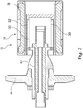
- the rotational structure 12 can be provided as a cylindrical structure 22 arranged around a rotor shaft 24 to which shaft an anode 26 can be mounted. Further, in addition, also a stator 28 is indicated surrounding the cylindrical structure 22. An inner concentric cylindrical structure 30 will provide a closing for the magnetic field.
- the shaft is rotatably supportable by bearings, which is not further shown.
- the rotor is a counterpart to a stator, for example the stator 28, for driving the rotatable anode 26.
- At least the circumferential of the rotational structure is made from copper-free material.
- the circumferential part can be made from carbon based material.
- the circumferential part is made from copper-free material, for example from metal-free material.
- winding may be arranged for mechanical support of the cylindrical structure.
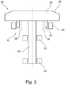
- the rotational structure 12 is provided as a cylindrical collar 32 on an anode disc 34 on a side opposite a side where a focal track 36 is provided.
- a dotted line 38 indicates the provision of a closing of the magnetic field.
- a stator 40 is also schematically indicated, as well as a bearing arrangement 42, 44, at least partially surrounding an anode shaft 46.
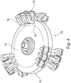
- the rotational structure 12 is provided integrally with an anode disc structure 48.
- the anode disc is made at least partially from carbon-fibre reinforced carbon, and the anode disc 48 comprises a primary winding structure such that the rotor magnetic field can be generated by the stator magnetic field.
- the primary winding is oriented in radial and tangential direction to the axis of rotation.
- Fig. 4 also shows further parts belonging to an X-ray tube 50, comprising the rotatable anode arrangement, such as the anode disc 26 in Fig. 2 or the anode 34 shown in Fig. 3 or the anode 48 shown in Fig. 4 , as well as a bearing arrangement with bearing such as the bearings 42, 44 in Fig. 3 and a stator, for example the stator 40 in Fig. 3 and a rotor 10, as discussed above.
- the rotatable anode arrangement is supported by the bearing arrangement and the rotor is provided as a rotor for an X-ray tube according to one of the above mentioned examples /embodiments.
- the stator is provided with electrical coils to generate a stator magnetic field to interact with the rotor such that electrical current is generated in the rotor generating the rotor magnetic field for rotating the anode arrangement.
- the rotatable anode arrangement is provided as an anode disc.
- the bearing arrangement is supported by the stator.
- a housing may be provided enclosing a tube volume (not further shown), inside which the anode arrangement, the bearing arrangement, the stator, and the rotor are provided, and inside which a vacuum for generating X-rays is provided.
- the stator and/or the bearing arrangement are connected to the housing according to a further example.
- the stator may comprise a number of C-shaped iron cores 52 around which a winding 54 is provided.
- the rotor is arranged partly between ends 56 of the C-shaped iron cores 52.
- the rotor 10 and its rotational structure 12 are provided integrally with the anode disc structure, such as the disc 48 in Fig. 4 .
- the stator is provided along an edge 58 of the anode disc structure.
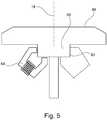
- the rotor may be provided as a stepped protrusion 60 of the anode disc 48 on a side opposite the side of the focal track.
- the stepped protrusion 60 is provided with an edge 62 such that a stator can interact on the edge 62.
- a number of C-shaped iron cores 64 is provided, around which iron cores a winding is provided.
- the stator 40 may be provided segmented comprising a plurality of stator elements, such as C-shaped iron cores 52, around which a winding 54 is provided.
- the rotor is arranged partly between the ends of the C-shaped iron cores, and the C-shaped iron cores of the stator are arranged with at least one gap 65 such that a focal spot is provided on the anode disc structure, upon which focal spot an electron beam can impinge.
- the segmented stator is also provided to the other embodiments/ examples.
- the segmented stator is only necessary if the stator is arranged such that a focal track is covered by the stator elements.
- the example of Fig. 4 may also be provided as a continuous stator without gaps in between.
- a different number of gaps may be provided, for example for a different segmentation.
- the arrangement of the rotor, i. e. the anode, between the ends of the C is provided for closing of the stator magnetic field generated by the stator.
- the C-shaped iron cores can be provided in at least two groups, each group comprising a number of C-shaped iron cores.
- Fig. 4 shows, as an example, three groups of three C-shaped iron cores each.
- Each group of the stator comprises at least one pair of C-shaped iron cores with a winding with an upper C-shaped core having the upper outer edge of the anode arranged between the ends of the C, and a lower C-shaped core having the lower outer edge of the anode arranged between the ends of the C.
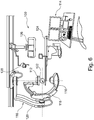
- FIG. 6 shows an X-ray imaging system 100 comprising an X-ray source 110, an X-ray detector 112, and a processing unit 114.
- the X-ray source 110 is provided as an X-ray tube according to the above-mentioned examples / embodiments.
- the processing unit 14 is provided to control the rotation by the rotor.
- the X-ray imaging system 100 is provided as a so-called C-arm structure 116 with a C-arm 118, to which the X-ray source and the X-ray detector are mounted to the ends of the C.
- a movable support structure 120 is provided for allowing a free movement around an object 122, arranged on a patient table 124.
- display arrangements 126 are provided, in addition to a lighting 128.
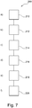
- Fig. 7 shows a method 200 for rotating an anode of an X-ray tube, comprising the following steps:
- a first electrical current is applied to a stator winding.
- a stator magnetic field is generated.
- the stator magnetic field is acting on the rotor, wherein the rotor comprises a rotational structure with a plurality of electrically conducting elements made from carbon composite based material, the ends thereof connected to each other.
- a second current is induced in the electrically conducting elements by the stator magnetic field, thereby generating a rotor magnetic field.
- the rotor magnetic field is interacting with the stator magnetic field.
- the anode is driven to rotation due to the interaction.
- the first step 210 is also referred to as step a), the second step 212 as step b), the third step 214 as step c), the fourth step 216 as step d), the fifth step 218 as step e), and the sixth step 220 as step f).
- a computer program or a computer program element is provided that is characterized by being adapted to execute the method steps of the method according to the invention, on an appropriate system.
- the computer program element might therefore be stored on a computer unit, which might also be part of an embodiment of the present invention.
- This computing unit may be adapted to perform or induce a performing of the steps of the method described above. Moreover, it may be adapted to operate the components of the above described apparatus.
- the computing unit can be adapted to operate automatically and/or to execute the orders of a user.
- a computer program may be loaded into a working memory of a data processor.
- the data processor may thus be equipped to carry out the method of the invention.
- This exemplary embodiment of the invention covers both, a computer program that right from the beginning uses the invention and a computer program that by means of an up-date turns an existing program into a program that uses the invention.
- a computer readable medium such as a CD-ROM
- the computer readable medium has a computer program element stored on it which computer program element is described by the preceding section.
- a computer program may be stored and/or distributed on a suitable medium, such as an optical storage medium or a solid state medium supplied together with or as part of other hardware, but may also be distributed in other forms, such as via the internet or other wired or wireless telecommunication systems.
- a suitable medium such as an optical storage medium or a solid state medium supplied together with or as part of other hardware, but may also be distributed in other forms, such as via the internet or other wired or wireless telecommunication systems.
- the computer program may also be presented over a network like the World Wide Web and can be downloaded into the working memory of a data processor from such a network.
Landscapes
- Engineering & Computer Science (AREA)
- Power Engineering (AREA)
- X-Ray Techniques (AREA)
Claims (14)
- Rotor (10) für eine Röntgenröhre, umfassend:- eine Drehstruktur (12) mit einer Vielzahl von elektrisch leitenden Elementen (14), deren Enden miteinander verbunden sind und die derartig vorgesehen sind, dass ein durch einen Stator erzeugtes externes Statormagnetfeld einen Strom in die elektrisch leitenden Elemente induziert, wobei der Strom ein Rotormagnetfeld erzeugt, um mit dem Statormagnetfeld zu interagieren;wobei mindestens die Vielzahl von elektrisch leitenden Elementen aus Kohlenstoffverbundmaterial besteht; und
dadurch gekennzeichnet, dass die Drehstruktur als ein zylindrischer Kragen (32) auf einer Anodenscheibe (34) auf einer Seite vorgesehen ist, die einer Seite, auf der die Brennfleckbahn (36) vorgesehen ist, gegenüberliegt. - Rotor (10) für eine Röntgenröhre, umfassend:- eine Drehstruktur (12) mit einer Vielzahl von elektrisch leitenden Elementen (14), deren Enden miteinander verbunden sind und die derartig vorgesehen sind, dass ein durch einen Stator erzeugtes externes Statormagnetfeld einen Strom in die elektrisch leitenden Elemente induziert, wobei der Strom ein Rotormagnetfeld erzeugt, um mit dem Statormagnetfeld zu interagieren;wobei mindestens die Vielzahl von elektrisch leitenden Elementen aus Kohlenstoffverbundmaterial besteht, das kohlenstofffaserverstärkten Kohlenstoff umfasst;
dadurch gekennzeichnet, dass die Drehstruktur einstückig mit einer Anodenscheibenstruktur (48) vorgesehen ist;
und die Anodenscheibe zumindest teilweise aus dem kohlenstofffaserverstärkten Kohlenstoff besteht; wobei die Kohlenstofffasern als primäre Faserwicklung vorgesehen sind, die derartig orientiert ist, dass der Strom in die elektrisch leitenden Elemente induziert werden kann; und
wobei die Anodenscheibe die primäre Faserwicklung umfasst, sodass das Rotormagnetfeld durch das Statormagnetfeld erzeugt werden kann. - Rotor (10) nach Anspruch 2, wobei die Drehstruktur als ein abgestufter Vorsprung (60) der Anodenscheibe (48) auf einer Seite vorgesehen ist, die der Seite der Brennfleckbahn gegenüberliegt; wobei der abgestufte Vorsprung derartig mit einem Rand (62) vorgesehen ist, dass ein Stator am Rand interagieren kann.
- Rotor nach Anspruch 1 bis 3, wobei die Kohlenstofffasern auf eine Weise orientiert sind, dass Hochmodul-Fasern den induzierten Stromfluss optimieren, während Fasern mit hoher Zugfestigkeit die erforderliche Zugfestigkeit bereitstellen.
- Röntgenröhre (50), umfassend:- eine drehbare Anodenanordnung (34);- eine Lageranordnung (42, 44);- einen Stator (40); und- einen Rotor (10);wobei die drehbare Anodenanordnung durch die Lageranordnung getragen wird; und
wobei der Rotor als ein Rotor für eine Röntgenröhre nach einem der vorstehenden Ansprüche vorgesehen ist; und
wobei der Stator mit elektrischen Spulen vorgesehen ist, um ein Statormagnetfeld zu erzeugen, um derartig mit dem Rotor zu interagieren, dass elektrischer Strom in dem Rotor erzeugt wird, welcher das Rotormagnetfeld zum Drehen der Anodenanordnung erzeugt. - Röntgenröhre nach Anspruch 5, wenn abhängig von Anspruch 1, wobei der Stator als zumindest teilweise den Kragen umschließend vorgesehen ist.
- Röntgenröhre nach Anspruch 5 oder 6, wobei der Stator eine Anzahl von C-förmigen Eisenkernen (52) umfasst, um die eine Wicklung (54) vorgesehen ist; und
wobei die Drehstruktur teilweise zwischen Enden (56) der C-förmigen Eisenkerne angeordnet ist. - Röntgenröhre nach Anspruch 5, wenn abhängig von Anspruch 2, wobei der Stator entlang eines Rands (58) der Anodenscheibenstruktur vorgesehen ist.
- Röntgenröhre nach Anspruch 7, wobei der Stator segmentiert ist; und
wobei die C-förmigen Eisenkerne des Stators mit mindestens einer Lücke (65) angeordnet sind, sodass ein Brennfleck auf der Anodenscheibenstruktur vorgesehen wird, auf den ein Elektronenstrahl auftreffen kann. - Röntgenbildgebungssystem (100), umfassend:- eine Röntgenquelle (110);- einen Röntgendetektor (112); und- eine Verarbeitungseinheit (114);wobei die Röntgenquelle als eine Röntgenröhre nach den Ansprüchen 5 bis 9 vorgesehen ist; und
wobei die Verarbeitungseinheit vorgesehen ist, um die Drehung durch den Rotor zu steuern. - Verfahren (200) zum Drehen einer Anode einer Röntgenröhre, umfassend die folgenden Schritte:a) Anlegen (210) eines ersten elektrischen Stroms an eine Statorwicklung;b) Erzeugen (212) eines Statormagnetfelds;c) Wirken (214) des Statormagnetfelds auf den Rotor; wobei der Rotor eine Drehstruktur mit einer Vielzahl von elektrisch leitenden Elementen aus Kohlenstoffverbundmaterial umfasst, deren Enden miteinander verbunden sind;
wobei vorgesehen ist:i) die Drehstruktur ist als ein zylindrischer Kragen (32) auf einer Anodenscheibe (34) auf einer Seite vorgesehen, die einer Seite, auf der die Brennfleckbahn (36) vorgesehen ist, gegenüberliegt; oderii) die Drehstruktur ist einstückig mit einer Anodenscheibenstruktur (48) vorgesehen, wobei das Kohlenstoffverbundmaterial kohlenstofffaserverstärkten Kohlenstoff umfasst;wobei die Anodenscheibe zumindest teilweise aus dem kohlenstofffaserverstärkten Kohlenstoff besteht; wobei die Kohlenstofffasern als primäre Faserwicklung vorgesehen sind, die derartig orientiert ist, dass der Strom in die elektrisch leitenden Elemente induziert werden kann; und wobei die Anodenscheibe die primäre Faserwicklung umfasst, sodass das Rotormagnetfeld durch das Statormagnetfeld erzeugt werden kann;d) Induzieren (216) eines zweiten Stroms in die elektrisch leitenden Elemente durch das Statormagnetfeld, wodurch ein Rotormagnetfeld erzeugt wird;e) Interagieren (218) des Rotormagnetfelds mit dem Statormagnetfeld; undf) Ansteuern (220) der Anode zur Drehung aufgrund der Interaktion. - Verfahren nach Anspruch 11, wobei in Fall ii) die Drehstruktur als ein abgestufter Vorsprung (60) der Anodenscheibe (48) auf einer Seite vorgesehen ist, die der Seite der Brennfleckbahn gegenüberliegt; wobei der abgestufte Vorsprung derartig mit einem Rand (62) vorgesehen ist, dass ein Stator am Rand interagieren kann.
- Computerprogrammelement zum Steuern eines Geräts nach einem der Ansprüche 1 bis 10, das, wenn es durch eine Verarbeitungseinheit ausgeführt wird, dafür ausgelegt ist, das Verfahren der Ansprüche 11 oder 12 durchzuführen.
- Computerlesbares Medium, auf dem das Programmelement von Anspruch 13 gespeichert ist.
Applications Claiming Priority (2)
| Application Number | Priority Date | Filing Date | Title |
|---|---|---|---|
| US201261649984P | 2012-05-22 | 2012-05-22 | |
| PCT/IB2013/053745 WO2013175335A1 (en) | 2012-05-22 | 2013-05-09 | X-ray tube rotor with carbon composite based material |
Publications (2)
| Publication Number | Publication Date |
|---|---|
| EP2852963A1 EP2852963A1 (de) | 2015-04-01 |
| EP2852963B1 true EP2852963B1 (de) | 2018-09-05 |
Family
ID=48692618
Family Applications (1)
| Application Number | Title | Priority Date | Filing Date |
|---|---|---|---|
| EP13731166.8A Not-in-force EP2852963B1 (de) | 2012-05-22 | 2013-05-09 | Röntgenröhre mit kohlenstoffverbundmaterial |
Country Status (6)
| Country | Link |
|---|---|
| US (1) | US9853511B2 (de) |
| EP (1) | EP2852963B1 (de) |
| JP (1) | JP6235571B2 (de) |
| CN (1) | CN104335317B (de) |
| RU (1) | RU2014151772A (de) |
| WO (1) | WO2013175335A1 (de) |
Families Citing this family (1)
| Publication number | Priority date | Publication date | Assignee | Title |
|---|---|---|---|---|
| WO2017161376A1 (en) * | 2016-03-18 | 2017-09-21 | Varex Imaging Corporation | Magnetic lift device for an x-ray tube |
Family Cites Families (26)
| Publication number | Priority date | Publication date | Assignee | Title |
|---|---|---|---|---|
| FR2126517A6 (de) * | 1971-02-09 | 1972-10-06 | Radiologie Cie Gle | |
| US4091301A (en) | 1974-07-08 | 1978-05-23 | Bbc Brown Boveri & Company Limited | Rotor end-winding support for high-speed electrical machine such as a turbo-generator |
| JPS59117058A (ja) * | 1982-12-24 | 1984-07-06 | Hitachi Ltd | 回転陽極x線管 |
| FR2548829B1 (fr) * | 1983-07-06 | 1985-11-22 | Thomson Csf | Tube a rayons x a anode tournante muni d'un dispositif d'ecoulement des charges |
| US4862763A (en) | 1984-01-09 | 1989-09-05 | Ltv Aerospace & Defense Company | Method and apparatus for manufacturing high speed rotors |
| JPS6266544A (ja) * | 1985-09-17 | 1987-03-26 | Shimadzu Corp | 回転陽極形x線管装置 |
| DE4210146A1 (de) * | 1992-03-27 | 1993-09-30 | Siemens Ag | Halterung einer Achse in einem Gehäuse |
| US5541975A (en) * | 1994-01-07 | 1996-07-30 | Anderson; Weston A. | X-ray tube having rotary anode cooled with high thermal conductivity fluid |
| US5799951A (en) * | 1996-11-21 | 1998-09-01 | Varian Associates, Inc. | Rotating sealing device |
| US5875228A (en) | 1997-06-24 | 1999-02-23 | General Electric Company | Lightweight rotating anode for X-ray tube |
| AT406205B (de) | 1997-10-30 | 2000-03-27 | Plansee Ag | Verfahren zur herstellung einer drehanoden-baueinheit |
| SE0001123L (sv) * | 2000-03-30 | 2001-10-01 | Abb Ab | Kraftkabel |
| DE10304936B3 (de) | 2003-02-06 | 2004-10-28 | Siemens Ag | Drehanode für eine Röntgenröhre mit einem Anodenkörper aus Faserwerkstoff sowie Verfahren zu deren Herstellung |
| DE10320361B3 (de) * | 2003-05-07 | 2004-12-16 | Siemens Ag | Vorrichtung mit einem in einem Fluid eingetauchten Drehkörper, insbesondere Röntgenstrahler |
| US20050218741A1 (en) * | 2004-03-18 | 2005-10-06 | Wnorowski Edward J Jr | Generators, transformers and stators containing high-strength, laminated, carbon-fiber windings |
| US7190765B2 (en) | 2004-07-26 | 2007-03-13 | General Electric Company | Bearing temperature and focal spot position controlled anode for a CT system |
| JP2006100032A (ja) * | 2004-09-28 | 2006-04-13 | Toshiba Corp | 回転陽極型x線管 |
| WO2008053403A2 (en) * | 2006-11-03 | 2008-05-08 | Philips Intellectual Property & Standards Gmbh | Switching scheme for a stereo rotating anode tube |
| CN101779267A (zh) * | 2007-08-16 | 2010-07-14 | 皇家飞利浦电子股份有限公司 | 用于旋转阳极型高功率x射线管构造的阳极盘结构的混合设计 |
| DE102008025702A1 (de) * | 2008-05-29 | 2009-12-10 | Siemens Aktiengesellschaft | Asynchronmaschine mit verbesserten mechanischen Eigenschaften und Verfahren zum Herstellen eines Läufers für eine Asynchronmaschine |
| DE102008049050A1 (de) | 2008-09-26 | 2010-04-08 | Siemens Aktiengesellschaft | Luftlager zum Lagern eines Körpers |
| JP2012510137A (ja) * | 2008-11-25 | 2012-04-26 | コーニンクレッカ フィリップス エレクトロニクス エヌ ヴィ | X線陽極 |
| WO2010070574A1 (en) | 2008-12-17 | 2010-06-24 | Koninklijke Philips Electronics N.V. | Attachment of a high-z focal track layer to a carbon-carbon composite substrate serving as a rotary anode target |
| EP2449572B1 (de) * | 2009-06-29 | 2017-03-08 | Koninklijke Philips N.V. | Anodentellerelement mit wärmeableitendem element |
| US8448328B2 (en) * | 2010-01-06 | 2013-05-28 | GM Global Technology Operations LLC | Methods of making aluminum based composite squirrel cage for induction rotor |
| WO2011148978A1 (ja) * | 2010-05-27 | 2011-12-01 | 矢崎総業株式会社 | 誘導モータの回転子及びそれを用いた誘導モータ |
-
2013
- 2013-05-09 EP EP13731166.8A patent/EP2852963B1/de not_active Not-in-force
- 2013-05-09 CN CN201380026658.3A patent/CN104335317B/zh not_active Expired - Fee Related
- 2013-05-09 WO PCT/IB2013/053745 patent/WO2013175335A1/en not_active Ceased
- 2013-05-09 US US14/396,808 patent/US9853511B2/en active Active
- 2013-05-09 RU RU2014151772A patent/RU2014151772A/ru not_active Application Discontinuation
- 2013-05-09 JP JP2015513304A patent/JP6235571B2/ja not_active Expired - Fee Related
Also Published As
| Publication number | Publication date |
|---|---|
| JP2015522909A (ja) | 2015-08-06 |
| WO2013175335A1 (en) | 2013-11-28 |
| CN104335317A (zh) | 2015-02-04 |
| JP6235571B2 (ja) | 2017-11-22 |
| RU2014151772A (ru) | 2016-07-20 |
| US9853511B2 (en) | 2017-12-26 |
| EP2852963A1 (de) | 2015-04-01 |
| US20150124937A1 (en) | 2015-05-07 |
| CN104335317B (zh) | 2017-07-18 |
Similar Documents
| Publication | Publication Date | Title |
|---|---|---|
| US12003152B2 (en) | Dual rotor electrical machines | |
| EP2579433A1 (de) | Rotor für einen induktionsmotor und induktionsmotor damit | |
| US20120032084A1 (en) | Drive with curved linear induction motor | |
| JP4808387B2 (ja) | 軸方向磁束型電動機で駆動されるx線管用アノードターゲット | |
| CN104285271B (zh) | 旋转阳极装置和x射线管 | |
| EP2852963B1 (de) | Röntgenröhre mit kohlenstoffverbundmaterial | |
| JP5893335B2 (ja) | X線管アセンブリ | |
| US8203249B1 (en) | Reducing the core-end heating in large power generators | |
| US10636612B2 (en) | Magnetic assist assembly having heat dissipation | |
| US2945141A (en) | Unidirectional high-voltage generator | |
| CN105125226A (zh) | X射线设备 | |
| EP2852962A1 (de) | Lastausgleich in einer röntgenröhre | |
| US6118203A (en) | High efficiency motor for x-ray generation | |
| JP2010080399A (ja) | 回転陽極型x線管装置 | |
| US10629403B1 (en) | Magnetic assist bearing | |
| US10672585B2 (en) | Vacuum penetration for magnetic assist bearing | |
| JP5766128B2 (ja) | X線管装置及びx線ct装置 | |
| JP2013134915A (ja) | 回転陽極x線管装置 | |
| CN106941063B (zh) | 旋转阳极、x射线管和具有x射线管的系统以及用于制造旋转阳极的转子的方法 | |
| JP2010027445A (ja) | 回転陽極型x線管装置 | |
| EP3422386A1 (de) | Drehanoden-röntgenquelle | |
| CN102468101A (zh) | X射线管热传递方法及系统 | |
| US20220302815A1 (en) | Field coil support structure and modular field coil design in a superconducting machine | |
| McNab et al. | Improvements in and relating to superconducting dynamo-electric machines | |
| JPS625546A (ja) | 回転陽極型x線管装置 |
Legal Events
| Date | Code | Title | Description |
|---|---|---|---|
| PUAI | Public reference made under article 153(3) epc to a published international application that has entered the european phase |
Free format text: ORIGINAL CODE: 0009012 |
|
| 17P | Request for examination filed |
Effective date: 20141222 |
|
| AK | Designated contracting states |
Kind code of ref document: A1 Designated state(s): AL AT BE BG CH CY CZ DE DK EE ES FI FR GB GR HR HU IE IS IT LI LT LU LV MC MK MT NL NO PL PT RO RS SE SI SK SM TR |
|
| AX | Request for extension of the european patent |
Extension state: BA ME |
|
| DAX | Request for extension of the european patent (deleted) | ||
| 17Q | First examination report despatched |
Effective date: 20160907 |
|
| STAA | Information on the status of an ep patent application or granted ep patent |
Free format text: STATUS: EXAMINATION IS IN PROGRESS |
|
| GRAP | Despatch of communication of intention to grant a patent |
Free format text: ORIGINAL CODE: EPIDOSNIGR1 |
|
| STAA | Information on the status of an ep patent application or granted ep patent |
Free format text: STATUS: GRANT OF PATENT IS INTENDED |
|
| INTG | Intention to grant announced |
Effective date: 20180326 |
|
| RIN1 | Information on inventor provided before grant (corrected) |
Inventor name: CHROST, WOLFGANG |
|
| GRAS | Grant fee paid |
Free format text: ORIGINAL CODE: EPIDOSNIGR3 |
|
| GRAA | (expected) grant |
Free format text: ORIGINAL CODE: 0009210 |
|
| STAA | Information on the status of an ep patent application or granted ep patent |
Free format text: STATUS: THE PATENT HAS BEEN GRANTED |
|
| AK | Designated contracting states |
Kind code of ref document: B1 Designated state(s): AL AT BE BG CH CY CZ DE DK EE ES FI FR GB GR HR HU IE IS IT LI LT LU LV MC MK MT NL NO PL PT RO RS SE SI SK SM TR |
|
| REG | Reference to a national code |
Ref country code: GB Ref legal event code: FG4D |
|
| REG | Reference to a national code |
Ref country code: CH Ref legal event code: EP |
|
| REG | Reference to a national code |
Ref country code: AT Ref legal event code: REF Ref document number: 1038829 Country of ref document: AT Kind code of ref document: T Effective date: 20180915 |
|
| REG | Reference to a national code |
Ref country code: IE Ref legal event code: FG4D |
|
| REG | Reference to a national code |
Ref country code: DE Ref legal event code: R096 Ref document number: 602013043113 Country of ref document: DE |
|
| REG | Reference to a national code |
Ref country code: NL Ref legal event code: MP Effective date: 20180905 |
|
| REG | Reference to a national code |
Ref country code: LT Ref legal event code: MG4D |
|
| PG25 | Lapsed in a contracting state [announced via postgrant information from national office to epo] |
Ref country code: BG Free format text: LAPSE BECAUSE OF FAILURE TO SUBMIT A TRANSLATION OF THE DESCRIPTION OR TO PAY THE FEE WITHIN THE PRESCRIBED TIME-LIMIT Effective date: 20181205 Ref country code: LT Free format text: LAPSE BECAUSE OF FAILURE TO SUBMIT A TRANSLATION OF THE DESCRIPTION OR TO PAY THE FEE WITHIN THE PRESCRIBED TIME-LIMIT Effective date: 20180905 Ref country code: RS Free format text: LAPSE BECAUSE OF FAILURE TO SUBMIT A TRANSLATION OF THE DESCRIPTION OR TO PAY THE FEE WITHIN THE PRESCRIBED TIME-LIMIT Effective date: 20180905 Ref country code: FI Free format text: LAPSE BECAUSE OF FAILURE TO SUBMIT A TRANSLATION OF THE DESCRIPTION OR TO PAY THE FEE WITHIN THE PRESCRIBED TIME-LIMIT Effective date: 20180905 Ref country code: NO Free format text: LAPSE BECAUSE OF FAILURE TO SUBMIT A TRANSLATION OF THE DESCRIPTION OR TO PAY THE FEE WITHIN THE PRESCRIBED TIME-LIMIT Effective date: 20181205 Ref country code: GR Free format text: LAPSE BECAUSE OF FAILURE TO SUBMIT A TRANSLATION OF THE DESCRIPTION OR TO PAY THE FEE WITHIN THE PRESCRIBED TIME-LIMIT Effective date: 20181206 Ref country code: SE Free format text: LAPSE BECAUSE OF FAILURE TO SUBMIT A TRANSLATION OF THE DESCRIPTION OR TO PAY THE FEE WITHIN THE PRESCRIBED TIME-LIMIT Effective date: 20180905 |
|
| REG | Reference to a national code |
Ref country code: AT Ref legal event code: MK05 Ref document number: 1038829 Country of ref document: AT Kind code of ref document: T Effective date: 20180905 |
|
| PG25 | Lapsed in a contracting state [announced via postgrant information from national office to epo] |
Ref country code: HR Free format text: LAPSE BECAUSE OF FAILURE TO SUBMIT A TRANSLATION OF THE DESCRIPTION OR TO PAY THE FEE WITHIN THE PRESCRIBED TIME-LIMIT Effective date: 20180905 Ref country code: AL Free format text: LAPSE BECAUSE OF FAILURE TO SUBMIT A TRANSLATION OF THE DESCRIPTION OR TO PAY THE FEE WITHIN THE PRESCRIBED TIME-LIMIT Effective date: 20180905 Ref country code: LV Free format text: LAPSE BECAUSE OF FAILURE TO SUBMIT A TRANSLATION OF THE DESCRIPTION OR TO PAY THE FEE WITHIN THE PRESCRIBED TIME-LIMIT Effective date: 20180905 |
|
| PG25 | Lapsed in a contracting state [announced via postgrant information from national office to epo] |
Ref country code: NL Free format text: LAPSE BECAUSE OF FAILURE TO SUBMIT A TRANSLATION OF THE DESCRIPTION OR TO PAY THE FEE WITHIN THE PRESCRIBED TIME-LIMIT Effective date: 20180905 Ref country code: AT Free format text: LAPSE BECAUSE OF FAILURE TO SUBMIT A TRANSLATION OF THE DESCRIPTION OR TO PAY THE FEE WITHIN THE PRESCRIBED TIME-LIMIT Effective date: 20180905 Ref country code: IS Free format text: LAPSE BECAUSE OF FAILURE TO SUBMIT A TRANSLATION OF THE DESCRIPTION OR TO PAY THE FEE WITHIN THE PRESCRIBED TIME-LIMIT Effective date: 20190105 Ref country code: PL Free format text: LAPSE BECAUSE OF FAILURE TO SUBMIT A TRANSLATION OF THE DESCRIPTION OR TO PAY THE FEE WITHIN THE PRESCRIBED TIME-LIMIT Effective date: 20180905 Ref country code: EE Free format text: LAPSE BECAUSE OF FAILURE TO SUBMIT A TRANSLATION OF THE DESCRIPTION OR TO PAY THE FEE WITHIN THE PRESCRIBED TIME-LIMIT Effective date: 20180905 Ref country code: CZ Free format text: LAPSE BECAUSE OF FAILURE TO SUBMIT A TRANSLATION OF THE DESCRIPTION OR TO PAY THE FEE WITHIN THE PRESCRIBED TIME-LIMIT Effective date: 20180905 Ref country code: IT Free format text: LAPSE BECAUSE OF FAILURE TO SUBMIT A TRANSLATION OF THE DESCRIPTION OR TO PAY THE FEE WITHIN THE PRESCRIBED TIME-LIMIT Effective date: 20180905 Ref country code: RO Free format text: LAPSE BECAUSE OF FAILURE TO SUBMIT A TRANSLATION OF THE DESCRIPTION OR TO PAY THE FEE WITHIN THE PRESCRIBED TIME-LIMIT Effective date: 20180905 Ref country code: ES Free format text: LAPSE BECAUSE OF FAILURE TO SUBMIT A TRANSLATION OF THE DESCRIPTION OR TO PAY THE FEE WITHIN THE PRESCRIBED TIME-LIMIT Effective date: 20180905 |
|
| PG25 | Lapsed in a contracting state [announced via postgrant information from national office to epo] |
Ref country code: PT Free format text: LAPSE BECAUSE OF FAILURE TO SUBMIT A TRANSLATION OF THE DESCRIPTION OR TO PAY THE FEE WITHIN THE PRESCRIBED TIME-LIMIT Effective date: 20190105 Ref country code: SM Free format text: LAPSE BECAUSE OF FAILURE TO SUBMIT A TRANSLATION OF THE DESCRIPTION OR TO PAY THE FEE WITHIN THE PRESCRIBED TIME-LIMIT Effective date: 20180905 Ref country code: SK Free format text: LAPSE BECAUSE OF FAILURE TO SUBMIT A TRANSLATION OF THE DESCRIPTION OR TO PAY THE FEE WITHIN THE PRESCRIBED TIME-LIMIT Effective date: 20180905 |
|
| REG | Reference to a national code |
Ref country code: DE Ref legal event code: R097 Ref document number: 602013043113 Country of ref document: DE |
|
| PLBE | No opposition filed within time limit |
Free format text: ORIGINAL CODE: 0009261 |
|
| STAA | Information on the status of an ep patent application or granted ep patent |
Free format text: STATUS: NO OPPOSITION FILED WITHIN TIME LIMIT |
|
| PG25 | Lapsed in a contracting state [announced via postgrant information from national office to epo] |
Ref country code: DK Free format text: LAPSE BECAUSE OF FAILURE TO SUBMIT A TRANSLATION OF THE DESCRIPTION OR TO PAY THE FEE WITHIN THE PRESCRIBED TIME-LIMIT Effective date: 20180905 |
|
| 26N | No opposition filed |
Effective date: 20190606 |
|
| PG25 | Lapsed in a contracting state [announced via postgrant information from national office to epo] |
Ref country code: SI Free format text: LAPSE BECAUSE OF FAILURE TO SUBMIT A TRANSLATION OF THE DESCRIPTION OR TO PAY THE FEE WITHIN THE PRESCRIBED TIME-LIMIT Effective date: 20180905 |
|
| REG | Reference to a national code |
Ref country code: CH Ref legal event code: PL |
|
| GBPC | Gb: european patent ceased through non-payment of renewal fee |
Effective date: 20190509 |
|
| PG25 | Lapsed in a contracting state [announced via postgrant information from national office to epo] |
Ref country code: MC Free format text: LAPSE BECAUSE OF FAILURE TO SUBMIT A TRANSLATION OF THE DESCRIPTION OR TO PAY THE FEE WITHIN THE PRESCRIBED TIME-LIMIT Effective date: 20180905 Ref country code: CH Free format text: LAPSE BECAUSE OF NON-PAYMENT OF DUE FEES Effective date: 20190531 Ref country code: LI Free format text: LAPSE BECAUSE OF NON-PAYMENT OF DUE FEES Effective date: 20190531 |
|
| REG | Reference to a national code |
Ref country code: BE Ref legal event code: MM Effective date: 20190531 |
|
| PG25 | Lapsed in a contracting state [announced via postgrant information from national office to epo] |
Ref country code: LU Free format text: LAPSE BECAUSE OF NON-PAYMENT OF DUE FEES Effective date: 20190509 |
|
| PG25 | Lapsed in a contracting state [announced via postgrant information from national office to epo] |
Ref country code: TR Free format text: LAPSE BECAUSE OF FAILURE TO SUBMIT A TRANSLATION OF THE DESCRIPTION OR TO PAY THE FEE WITHIN THE PRESCRIBED TIME-LIMIT Effective date: 20180905 |
|
| PG25 | Lapsed in a contracting state [announced via postgrant information from national office to epo] |
Ref country code: IE Free format text: LAPSE BECAUSE OF NON-PAYMENT OF DUE FEES Effective date: 20190509 Ref country code: GB Free format text: LAPSE BECAUSE OF NON-PAYMENT OF DUE FEES Effective date: 20190509 |
|
| PG25 | Lapsed in a contracting state [announced via postgrant information from national office to epo] |
Ref country code: BE Free format text: LAPSE BECAUSE OF NON-PAYMENT OF DUE FEES Effective date: 20190531 |
|
| PG25 | Lapsed in a contracting state [announced via postgrant information from national office to epo] |
Ref country code: FR Free format text: LAPSE BECAUSE OF NON-PAYMENT OF DUE FEES Effective date: 20190531 |
|
| PG25 | Lapsed in a contracting state [announced via postgrant information from national office to epo] |
Ref country code: CY Free format text: LAPSE BECAUSE OF FAILURE TO SUBMIT A TRANSLATION OF THE DESCRIPTION OR TO PAY THE FEE WITHIN THE PRESCRIBED TIME-LIMIT Effective date: 20180905 |
|
| PG25 | Lapsed in a contracting state [announced via postgrant information from national office to epo] |
Ref country code: MT Free format text: LAPSE BECAUSE OF FAILURE TO SUBMIT A TRANSLATION OF THE DESCRIPTION OR TO PAY THE FEE WITHIN THE PRESCRIBED TIME-LIMIT Effective date: 20180905 Ref country code: HU Free format text: LAPSE BECAUSE OF FAILURE TO SUBMIT A TRANSLATION OF THE DESCRIPTION OR TO PAY THE FEE WITHIN THE PRESCRIBED TIME-LIMIT; INVALID AB INITIO Effective date: 20130509 |
|
| PG25 | Lapsed in a contracting state [announced via postgrant information from national office to epo] |
Ref country code: MK Free format text: LAPSE BECAUSE OF FAILURE TO SUBMIT A TRANSLATION OF THE DESCRIPTION OR TO PAY THE FEE WITHIN THE PRESCRIBED TIME-LIMIT Effective date: 20180905 |
|
| PGFP | Annual fee paid to national office [announced via postgrant information from national office to epo] |
Ref country code: DE Payment date: 20220628 Year of fee payment: 11 |
|
| REG | Reference to a national code |
Ref country code: DE Ref legal event code: R119 Ref document number: 602013043113 Country of ref document: DE |
|
| PG25 | Lapsed in a contracting state [announced via postgrant information from national office to epo] |
Ref country code: DE Free format text: LAPSE BECAUSE OF NON-PAYMENT OF DUE FEES Effective date: 20241203 |