EP2852030A1 - Dispositif de refroidissement pour une machine électrique et machine électrique comprenant un dispositif de refroidissement - Google Patents
Dispositif de refroidissement pour une machine électrique et machine électrique comprenant un dispositif de refroidissement Download PDFInfo
- Publication number
- EP2852030A1 EP2852030A1 EP13185286.5A EP13185286A EP2852030A1 EP 2852030 A1 EP2852030 A1 EP 2852030A1 EP 13185286 A EP13185286 A EP 13185286A EP 2852030 A1 EP2852030 A1 EP 2852030A1
- Authority
- EP
- European Patent Office
- Prior art keywords
- stator
- channels
- cooling device
- cooling
- electric machine
- Prior art date
- Legal status (The legal status is an assumption and is not a legal conclusion. Google has not performed a legal analysis and makes no representation as to the accuracy of the status listed.)
- Withdrawn
Links
Images


Classifications
-
- H—ELECTRICITY
- H02—GENERATION; CONVERSION OR DISTRIBUTION OF ELECTRIC POWER
- H02K—DYNAMO-ELECTRIC MACHINES
- H02K1/00—Details of the magnetic circuit
- H02K1/06—Details of the magnetic circuit characterised by the shape, form or construction
- H02K1/12—Stationary parts of the magnetic circuit
- H02K1/20—Stationary parts of the magnetic circuit with channels or ducts for flow of cooling medium
-
- H—ELECTRICITY
- H02—GENERATION; CONVERSION OR DISTRIBUTION OF ELECTRIC POWER
- H02K—DYNAMO-ELECTRIC MACHINES
- H02K9/00—Arrangements for cooling or ventilating
- H02K9/19—Arrangements for cooling or ventilating for machines with closed casing and closed-circuit cooling using a liquid cooling medium, e.g. oil
-
- H—ELECTRICITY
- H02—GENERATION; CONVERSION OR DISTRIBUTION OF ELECTRIC POWER
- H02K—DYNAMO-ELECTRIC MACHINES
- H02K3/00—Details of windings
- H02K3/04—Windings characterised by the conductor shape, form or construction, e.g. with bar conductors
- H02K3/24—Windings characterised by the conductor shape, form or construction, e.g. with bar conductors with channels or ducts for cooling medium between the conductors
Definitions
- the invention relates to a cooling device for electrical machines, in particular generators, and an electric machine with a cooling device according to the invention.
- FIG. 3 shows an electrical machine 101 according to the prior art, in more detail FIG. 3 a cross section of a quadrant of an electric machine.
- the structure of the electric machine 101 is generally rotationally symmetrical about a rotation axis 5.
- On the rotation axis 5 is a rotor 4.
- a stator 2 Concentric or substantially concentric to the rotor 4, a stator 2 is arranged so that upon rotation of the rotation axis 5 a electrical voltage is induced in the stator 2 in the case of a generator. Accordingly, when an alternating voltage is applied to the stator 2, the rotor 4 can be excited to rotate about the axis of rotation 5, as is the case with an electric motor, in particular a three-phase motor.
- the stator 2 consists of a stator winding or stator winding 2a.
- the stator winding 2a consists of individual laminations 2b (also Statorblechwovene or stator laminations) and at least one Statorwicklungskopf 2c (also stator winding head or winding head).
- individual laminations 2b are spaced apart by a distance 2d.
- heat is required which makes it necessary to efficiently cool the electric machine 101.
- the cooling is necessary because insulation materials are used by the materials used to insulate the housing of electricity and / or live parts that retain their isolation effect only up to a threshold temperature.
- a blower mounted on the axis of rotation and / or on the housing can be used to promote a coolant flow from outside the electric machine 101 into the interior of the electrical machine and / or to circulate in the machine.
- a geometry of the individual active components rotor 4, stator 2 and / or stator winding head 2c results in a specific ratio in which the coolant mass flow flows against individual ones of these active components and causes a corresponding cooling. This ratio of the individual mass flows of coolant can generally no longer be changed for the electric machine 101. This results in a limitation of the cooling of each of the active components.
- the coolant for example gas and / or cooling liquid in the electric machine 101
- heat which is absorbed by the coolant can be withdrawn by a corresponding radiator through a corresponding thermodynamic cycle and can be supplied to the electric machine 101 again , so that a continuous cooling of the electric machine 101 is possible.
- the invention has therefore set itself the task of providing a cooling device such that in particular the stator 2 can be selectively cooled.
- the present invention proposes an electric machine before, comprising a cooling device according to the invention for cooling the stator.
- the cooling device for an electric machine is in particular a cooling device for an electric machine with a stator, wherein the stator comprises at least one stator winding with at least one stator core and at least one stator winding head.
- the stator is also referred to below as a stator, according to the stator winding head as Statorwicklungskopf and the stator core and as stator laminated core.
- Statorwicklungskopf and the stator core and as stator laminated core.
- the cooling device comprises a multiplicity of channels through which coolant can flow.
- the plurality of channels is connected at a first end or end portion to a pressure accumulator.
- a second end or a second end portion of the plurality of channels opens either in an impingement cooling plate and / or ends in a channel of a stator winding head, this function preferably takes over the impingement cooling plate.
- Such a cooling device is advantageous because it can set a targeted cooling of the stator.
- a selection of the plurality of channels between each of the stator laminations can run.
- a selection of the plurality of channels may extend into openings within the stator 2, for example in channels between individual ones of the stator lamination packages.
- the ability to select which selection of the plurality of channels is in channels between individual stator cores and / or in stator openings, particularly the stator winding head, allows the relative cooling of individual stator cores to be adjusted to cool individual stator core heads.
- the first selection of the channels extending between each of the stator lamination packages can be equal to the selection which extends in openings of the stator winding head.
- the selection of the channels extending in the openings of the stator winding head can also a selection of the running between each of the stator laminations plurality of channels.
- a second selection of the plurality of channels may be in channels within the stator.
- a weighting of a cooling of individual stator core stacks to individual ones of the stator winding heads can be achieved by appropriate selection of the plurality of channels.
- the cooling device comprises outlet means.
- the outlet means may be provided on the impingement cooling plate.
- the outlet means may be provided on the at least one channel of the stator winding head by terminating at least a selection of the plurality of channels.
- the cooling device comprises a coolant, which flows from the pressure accumulator to the second end of the channels, provided that at the second end of the channels there is a lower static pressure than in the pressure accumulator.
- a lower pressure at the second end of the channels is therefore advantageous, since a direction in which the coolant flows is defined, so that a flow direction of the coolant can be imparted to a corresponding cooling circuit.
- the outlet means may be designed so that in the cooling mode, the static pressure at the second end of the channels is less than in the pressure accumulator 10a.
- a corresponding provision of the outlet means is advantageous because the desired flow direction of the coolant is achieved in the thermodynamic cycle.
- sufficient design or dimensioning of the outlet means for example on the impingement cooling plate, effective cooling of the stator results.
- the impingement cooling plate may be attachable to an end portion of the at least one stator core.
- the impingement cooling plate may be attachable to an end portion of the at least one stator core.
- the cooling device may comprise a second plurality of channels through which a coolant can pass, which are connected in a first end or end section to a second pressure accumulator and terminate at a second end or end section in each case in a second impingement cooling plate and / or in a channel of the stator winding head ,
- stator winding package can be effectively cooled by the first and second baffle cooling plates.
- stator winding heads can be effectively cooled by either the second ends of the first channels and / or the second ends of the second channels, each terminating in a channel of the stator winding head.
- At least one selection can also run for the second channels between individual stator core stacks and / or a selection of the second channels can extend in openings of the stator lamination stack.
- a second selection of the second channels extend at least in sections in channels of the stator winding head.
- the second impingement cooling plate of the cooling device at a second end portion of the stator core (also stator core or laminated core) be attachable. Therefore, the stator winding package at both ends can be effectively made effective by means of the first and second baffle cooling plates cool, which allows more efficient heat dissipation.
- the second pressure accumulator may also contain a coolant which flows from the second pressure accumulator to the second end of the second passage, provided there is a lower static pressure at the second end of the second passage than in the second pressure accumulator.
- a coolant which flows from the second pressure accumulator to the second end of the second passage, provided there is a lower static pressure at the second end of the second passage than in the second pressure accumulator.
- the cooling device may comprise second outlet means, which are designed so that in the cooling operation, the static pressure at the second end of the second channels is less than in the second pressure accumulator, as has already been explained for the first outlet means.
- Cooling operation should be designed both for the first outlet means and for the second outlet means in such a way that measurable cooling of the electrical machine takes place by the cooling device. This can be done during operation of the electrical machine and / or at standstill of the electrical machine.
- first channels and second channels alternate, which allows space-saving cooling of the stator.
- first channels and second channels alternate, which allows space-saving cooling of the stator.
- the invention relates to an electrical machine.
- This electric machine comprises a rotor and a stator, wherein the stator comprises at least one stator winding with at least one stator core and at least one stator winding head.
- the electric machine according to the invention further comprises a described above cooling device according to the present invention.
- the electrical machine according to the invention may preferably be a generator and / or a motor.
- FIG. 1 shows a section of an electric machine 100, in particular a section of a stator 2, which comprises a cooling device 1 according to the present invention in a first embodiment.
- the stator 2 consists of a plurality of stator laminations 2b (also laminated cores or stator lamination) as shown.
- the individual stator laminations 2b are arranged so that run between these first channels 6a.
- the first channels 6a are connected to a pressure accumulator 10 at first ends or first end portions 7a.
- the first channels 6a are either fluidly connected to an impingement cooling plate 8 and / or arranged in a channel of a stator winding head 2c. If in the Pressure vessel 10 (in FIG.
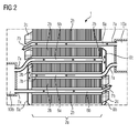
- FIG. 2 shows by way of example a cooling device 1 according to another embodiment of the invention, which is mounted in an electric machine 100, wherein FIG. 2 , how nice FIG. 1 only shows a section of a quadrant of the electric machine 100, as far as it is for the understanding of the invention Cooling device 1 and / or the electric machine 100 according to the invention is required.
- a plurality of second channels 6b are provided which emanate from a second pressure accumulator 10b. First ends 7a of the second channels 6b terminate in the second pressure accumulator 10b.
- a second end 7b of the second channels 6b terminates in a second baffle cooling plate 8b and / or in a stator winding head 2c.
- the arrangement of the stator winding head 2c and / or the first baffle cooling plate 8a and the second baffle cooling plate 8b is shown in FIG FIG. 2 given only by way of example and is intended to explain the principle of the second embodiment of the invention.
- the more effective cooling of the laminated stator laminates 2b also results in more effective cooling of the stator. It is of interest to provide a lower static pressure at the respective second end portions 7b of the first passages 6a and / or at the respective second end portions 7b of the second passages 6b than in the respectively connected first or second pressure vessels 10a, 10b to supply the coolant in the Inside the first channels 6a and / or inside the second channels 6b to impose a desired flow direction and thus without further drive means, such as in the form of pumps, a flow direction of the thermodynamic cycle process, as used for cooling the stator 2, provide.
- first and second channels 6a, 6b could be used, respectively with a further pressure vessel (not shown) and possibly another impact cooling plate (not shown) are connected.
- refrigerant for the embodiments of the invention, either a gaseous refrigerant may be used, for example, air, oxygen and / or hydrogen.
- Hydrogen would be particularly advantageous due to the high heat capacity and thus the high ability to remove heat from the stator laminations 2b and / or the stator winding heads 2c.
- safety precautions are required when using hydrogen as a coolant in order to avoid a blast gas explosion. Such safety devices are known to those skilled in the art, are not required for the understanding of the present invention and are therefore not further explained in connection with the present invention.
- a liquid as coolant, which flows in first channels 6a and / or second channels 6b and in other channels.
- a non-conductive liquid for example distilled water
- generator oil can also be used.
- electrically conductive cooling means which in particular flow out of the second ends 7b within the stator winding heads 2c, it must be ensured that this coolant does not cause a short circuit between electrically conductive components of the stator winding 2a or of the stator 2.
- a conductive coolant causes a short circuit between the stator 2 and / or the rotor, as well as between other electrically conductive components of the electric machine 1.
- appropriate arrangements are known to those skilled in the art and therefore in connection with the present description not explained further.
- stator laminations 2b also stator laminations, stator laminations, stator laminations, or stator
- the pressure vessels 10a, 10b would have to be mounted on the rotation axis 5 and co-rotate with the rotation of the rotation axis 5, which makes it difficult to arrange the cooling device 1 on the rotor 4.
- cooling device 1 can be combined with other cooling devices of an electric machine 100 so as to achieve a required cooling of the stator 2, the rotor 4 and / or the stator winding heads 2c.
- the present invention also discloses an electric machine 100 having a rotor 4 (shown in FIG Fig. 3 ) and a stator 2, wherein the stator comprises at least one stator winding 2a with at least one stator laminated core 2b, as in FIGS. 1 and 2 shown, wherein the electric machine 100, the cooling device 1 according to the invention, as in connection with FIGS. 1 and 2 includes.
- the electric machine according to the invention may be without limitation a generator and / or a motor.
- the present invention is not limited to the embodied embodiments of the cooling device 1 and / or the electric machine 100.
- the invention has been illustrated and described in detail by the preferred embodiments of the cooling apparatus 1 as well as preferred embodiments of the electric machine 100, the invention is not limited by the examples disclosed herein. Rather, variations are those disclosed herein Embodiments can be derived by the person skilled in the art without departing from the scope of the invention.
Priority Applications (6)
| Application Number | Priority Date | Filing Date | Title |
|---|---|---|---|
| EP13185286.5A EP2852030A1 (fr) | 2013-09-20 | 2013-09-20 | Dispositif de refroidissement pour une machine électrique et machine électrique comprenant un dispositif de refroidissement |
| JP2016515400A JP2016530855A (ja) | 2013-09-20 | 2014-09-03 | 電気機械のための冷却装置および冷却装置を有する電気機械 |
| CN201480051954.3A CN105556801A (zh) | 2013-09-20 | 2014-09-03 | 用于电机的冷却设备和包括冷却设备的电机 |
| US15/021,600 US20160226325A1 (en) | 2013-09-20 | 2014-09-03 | Cooling device for an electric machine and electric machine comprising a cooling device |
| PCT/EP2014/068680 WO2015039864A2 (fr) | 2013-09-20 | 2014-09-03 | Dispositif de refroidissement pour moteur électrique et moteur électrique comprenant un dispositif de refroidissement |
| EP14758903.0A EP3014743A2 (fr) | 2013-09-20 | 2014-09-03 | Dispositif de refroidissement pour moteur électrique et moteur électrique comprenant un dispositif de refroidissement |
Applications Claiming Priority (1)
| Application Number | Priority Date | Filing Date | Title |
|---|---|---|---|
| EP13185286.5A EP2852030A1 (fr) | 2013-09-20 | 2013-09-20 | Dispositif de refroidissement pour une machine électrique et machine électrique comprenant un dispositif de refroidissement |
Publications (1)
| Publication Number | Publication Date |
|---|---|
| EP2852030A1 true EP2852030A1 (fr) | 2015-03-25 |
Family
ID=49230581
Family Applications (2)
| Application Number | Title | Priority Date | Filing Date |
|---|---|---|---|
| EP13185286.5A Withdrawn EP2852030A1 (fr) | 2013-09-20 | 2013-09-20 | Dispositif de refroidissement pour une machine électrique et machine électrique comprenant un dispositif de refroidissement |
| EP14758903.0A Withdrawn EP3014743A2 (fr) | 2013-09-20 | 2014-09-03 | Dispositif de refroidissement pour moteur électrique et moteur électrique comprenant un dispositif de refroidissement |
Family Applications After (1)
| Application Number | Title | Priority Date | Filing Date |
|---|---|---|---|
| EP14758903.0A Withdrawn EP3014743A2 (fr) | 2013-09-20 | 2014-09-03 | Dispositif de refroidissement pour moteur électrique et moteur électrique comprenant un dispositif de refroidissement |
Country Status (5)
| Country | Link |
|---|---|
| US (1) | US20160226325A1 (fr) |
| EP (2) | EP2852030A1 (fr) |
| JP (1) | JP2016530855A (fr) |
| CN (1) | CN105556801A (fr) |
| WO (1) | WO2015039864A2 (fr) |
Cited By (1)
| Publication number | Priority date | Publication date | Assignee | Title |
|---|---|---|---|---|
| EP3474424A1 (fr) | 2017-10-23 | 2019-04-24 | Audi Ag | Machine électrique et véhicule automobile |
Families Citing this family (7)
| Publication number | Priority date | Publication date | Assignee | Title |
|---|---|---|---|---|
| FR3066053B1 (fr) * | 2017-05-03 | 2019-06-07 | Safran Helicopter Engines | Machine electrique a materiau a changement de phase d'un demarreur-generateur d'une turbomachine |
| CN107276275B (zh) * | 2017-08-02 | 2019-09-13 | 华中科技大学 | 一种轴向冷却电机 |
| EP3460206A1 (fr) * | 2017-09-21 | 2019-03-27 | Siemens Aktiengesellschaft | Procédé de fonctionnement d'une turbine à vapeur |
| CN109385577A (zh) * | 2018-05-14 | 2019-02-26 | 滨州学院 | 一种制备永磁材料的工艺及永磁电机 |
| CN109546780B (zh) * | 2018-05-14 | 2023-06-09 | 滨州学院 | 一种带有三级冷却的工程车用永磁发电机 |
| CN108736631A (zh) * | 2018-06-29 | 2018-11-02 | 李忠亮 | 高功率密度的电机 |
| DE102022117308A1 (de) | 2022-07-12 | 2024-01-18 | Bayerische Motoren Werke Aktiengesellschaft | Statorkernkühlungsanordnung für eine elektrische Antriebsmaschine |
Citations (2)
| Publication number | Priority date | Publication date | Assignee | Title |
|---|---|---|---|---|
| DE10256189A1 (de) * | 2002-12-02 | 2004-06-17 | Cornelius Peter | Hydraulisches Aggregat |
| DE102012201171A1 (de) * | 2012-01-27 | 2013-08-01 | Siemens Aktiengesellschaft | Elektrische Maschine, Lokomotive mit einer elektrischen Maschine und Verfahren zum Kühlen einer elektrischen Maschine |
Family Cites Families (16)
| Publication number | Priority date | Publication date | Assignee | Title |
|---|---|---|---|---|
| JPS5143304U (fr) * | 1974-09-26 | 1976-03-31 | ||
| JPS6149566U (fr) * | 1984-09-03 | 1986-04-03 | ||
| JPH0810973B2 (ja) * | 1988-04-08 | 1996-01-31 | ファナック株式会社 | 気体による内部冷却型モータ |
| DE4229395C2 (de) * | 1992-09-03 | 1995-06-08 | Licentia Gmbh | Oberflächengekühlte, geschlossene elektrische Maschine |
| US5365132A (en) * | 1993-05-27 | 1994-11-15 | General Electric Company | Lamination for a dynamoelectric machine with improved cooling capacity |
| JP2003009455A (ja) * | 2001-06-22 | 2003-01-10 | Yaskawa Electric Corp | モータの冷却構造 |
| US6882068B2 (en) * | 2002-10-08 | 2005-04-19 | General Electric Company | Forced air stator ventilation system and stator ventilation method for superconducting synchronous machine |
| JP2005143268A (ja) * | 2003-11-10 | 2005-06-02 | Toyota Central Res & Dev Lab Inc | 回転電機 |
| IT1392107B1 (it) * | 2008-11-28 | 2012-02-09 | Lucchi | Parte statorica di macchina elettrica a flusso assiale con sistema di raffreddamento a liquido. |
| EP2393188A4 (fr) * | 2009-03-05 | 2017-05-03 | Sanyo Denki Co., Ltd. | Induit pour moteur linéaire |
| JP5189615B2 (ja) * | 2010-04-02 | 2013-04-24 | 三菱電機株式会社 | 磁石発電機 |
| US8816546B2 (en) * | 2010-09-23 | 2014-08-26 | Northern Power Systems, Inc. | Electromagnetic rotary machines having modular active-coil portions and modules for such machines |
| EP2451058A1 (fr) * | 2010-11-04 | 2012-05-09 | Siemens Aktiengesellschaft | Collecteur soudé pour segment de noyau de stator |
| DE102010064010A1 (de) * | 2010-12-23 | 2012-06-28 | Siemens Aktiengesellschaft | Elektrische Maschine mit geschlossenem, autarkem Kühlmediumkreislauf |
| KR101418291B1 (ko) * | 2011-04-27 | 2014-07-11 | 엘지전자 주식회사 | 전동기 및 이를 구비한 전기차량 |
| JP6107523B2 (ja) * | 2013-08-02 | 2017-04-05 | マツダ株式会社 | 回転電機 |
-
2013
- 2013-09-20 EP EP13185286.5A patent/EP2852030A1/fr not_active Withdrawn
-
2014
- 2014-09-03 CN CN201480051954.3A patent/CN105556801A/zh active Pending
- 2014-09-03 JP JP2016515400A patent/JP2016530855A/ja active Pending
- 2014-09-03 US US15/021,600 patent/US20160226325A1/en not_active Abandoned
- 2014-09-03 WO PCT/EP2014/068680 patent/WO2015039864A2/fr active Application Filing
- 2014-09-03 EP EP14758903.0A patent/EP3014743A2/fr not_active Withdrawn
Patent Citations (2)
| Publication number | Priority date | Publication date | Assignee | Title |
|---|---|---|---|---|
| DE10256189A1 (de) * | 2002-12-02 | 2004-06-17 | Cornelius Peter | Hydraulisches Aggregat |
| DE102012201171A1 (de) * | 2012-01-27 | 2013-08-01 | Siemens Aktiengesellschaft | Elektrische Maschine, Lokomotive mit einer elektrischen Maschine und Verfahren zum Kühlen einer elektrischen Maschine |
Cited By (3)
| Publication number | Priority date | Publication date | Assignee | Title |
|---|---|---|---|---|
| EP3474424A1 (fr) | 2017-10-23 | 2019-04-24 | Audi Ag | Machine électrique et véhicule automobile |
| DE102017218865A1 (de) | 2017-10-23 | 2019-04-25 | Audi Ag | Elektrische Maschine und Kraftfahrzeug |
| US10693350B2 (en) | 2017-10-23 | 2020-06-23 | Audi Ag | Electric machine cooling system and motor vehicle |
Also Published As
| Publication number | Publication date |
|---|---|
| JP2016530855A (ja) | 2016-09-29 |
| EP3014743A2 (fr) | 2016-05-04 |
| WO2015039864A2 (fr) | 2015-03-26 |
| WO2015039864A3 (fr) | 2015-09-03 |
| US20160226325A1 (en) | 2016-08-04 |
| CN105556801A (zh) | 2016-05-04 |
Similar Documents
| Publication | Publication Date | Title |
|---|---|---|
| EP2852030A1 (fr) | Dispositif de refroidissement pour une machine électrique et machine électrique comprenant un dispositif de refroidissement | |
| DE102012213710B4 (de) | Kühlsystem für eine stromumwandlungsvorrichtung | |
| DE102011082353B4 (de) | Stator für einen Elektromotor | |
| DE102008034542B4 (de) | Elektromotorsystem | |
| DE102010029986A1 (de) | Dynamoelektrische Maschine mit Luft-Flüssigkeitskühlung | |
| DE19645272A1 (de) | Gasgekühlte elektrische Maschine | |
| WO2004027960A1 (fr) | Machine electrique comprenant un stator a demi-bobines refroidies | |
| WO2015124360A2 (fr) | Refroidissement d'une machine électrique | |
| EP2572442A2 (fr) | Épanouissement polaire | |
| DE102017105891A1 (de) | Drehende elektrische Maschine | |
| DE202012007328U1 (de) | Dynamoelektrische Maschine mit einem inneren geschlossenen Luftkühlkreislauf | |
| DE3629044A1 (de) | Statische erregervorrichtung fuer eine dynamoelektrische maschine | |
| DE3145937A1 (de) | "statische erregeranordnung und damit ausgeruestete dynamomaschine" | |
| DE102013100166A1 (de) | Drehende elektrische Maschine | |
| EP3474424B1 (fr) | Machine électrique et véhicule automobile | |
| DE102012204197A1 (de) | Elektrische Maschine mit Phasentrenner | |
| DE102020105790A1 (de) | Kühlkonzept zur Schleuderkühlung von elektrischen Maschinen über ein Phasenwechselmaterial (PCM) | |
| DE102008002299A1 (de) | Rotor mit innengekühlter Rotorwicklung | |
| WO2014131738A1 (fr) | Module de batterie pouvant être activé | |
| DE102020109482B4 (de) | Verfahren zum Herstellen eines Stators für eine elektrische Maschine, entsprechender Stator sowie Verfahren zum Betreiben einer elektrischen Maschine, entsprechender Stator sowie Verfahren zum Betreiben einer elektrischen Maschine | |
| EP2911276A1 (fr) | Circuit de refroidissement comprenant au moins deux fluides de refroidissement pour machine électrique | |
| EP1850463B1 (fr) | Procédé et dispositif destinés à la fabrication de liaisons soudées sur des conducteurs d'une machine électrique | |
| EP4193450A1 (fr) | Éolienne ayant au moins une machine dynamo-électrique | |
| DE102020105788A1 (de) | Kühlkonzept zur direkten Fluidkühlung von senkrecht eingebauten elektrischen Maschinen über ein Phasenwechselmaterial (PCM) | |
| EP2975729A1 (fr) | Générateur d'éolienne |
Legal Events
| Date | Code | Title | Description |
|---|---|---|---|
| PUAI | Public reference made under article 153(3) epc to a published international application that has entered the european phase |
Free format text: ORIGINAL CODE: 0009012 |
|
| 17P | Request for examination filed |
Effective date: 20130920 |
|
| AK | Designated contracting states |
Kind code of ref document: A1 Designated state(s): AL AT BE BG CH CY CZ DE DK EE ES FI FR GB GR HR HU IE IS IT LI LT LU LV MC MK MT NL NO PL PT RO RS SE SI SK SM TR |
|
| AX | Request for extension of the european patent |
Extension state: BA ME |
|
| STAA | Information on the status of an ep patent application or granted ep patent |
Free format text: STATUS: THE APPLICATION IS DEEMED TO BE WITHDRAWN |
|
| 18D | Application deemed to be withdrawn |
Effective date: 20150926 |