EP2851330A2 - Guide-câble de grue - Google Patents
Guide-câble de grue Download PDFInfo
- Publication number
- EP2851330A2 EP2851330A2 EP14184373.0A EP14184373A EP2851330A2 EP 2851330 A2 EP2851330 A2 EP 2851330A2 EP 14184373 A EP14184373 A EP 14184373A EP 2851330 A2 EP2851330 A2 EP 2851330A2
- Authority
- EP
- European Patent Office
- Prior art keywords
- cable guide
- spacers
- guide according
- boom
- crane
- Prior art date
- Legal status (The legal status is an assumption and is not a legal conclusion. Google has not performed a legal analysis and makes no representation as to the accuracy of the status listed.)
- Granted
Links
Images


Classifications
-
- B—PERFORMING OPERATIONS; TRANSPORTING
- B66—HOISTING; LIFTING; HAULING
- B66C—CRANES; LOAD-ENGAGING ELEMENTS OR DEVICES FOR CRANES, CAPSTANS, WINCHES, OR TACKLES
- B66C23/00—Cranes comprising essentially a beam, boom, or triangular structure acting as a cantilever and mounted for translatory of swinging movements in vertical or horizontal planes or a combination of such movements, e.g. jib-cranes, derricks, tower cranes
- B66C23/62—Constructional features or details
- B66C23/64—Jibs
- B66C23/70—Jibs constructed of sections adapted to be assembled to form jibs or various lengths
- B66C23/701—Jibs constructed of sections adapted to be assembled to form jibs or various lengths telescopic
Definitions
- the invention relates to a crane cable guide, in particular a cable guide for a telescopic crane. It can be used on all crane ropes that extend along the crane jib, for example the crane hoist rope.
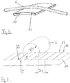
- FIG. 6 represents the front part of a telescoping telescopic boom whose boom shots on the upper part of their collars 20A to 20D ball-bearing rope rollers 23, via which a hoisting rope from a hoist winch, not shown, to the head roller 24 of the boom head 25 may extend.
- the line indicated by the reference numeral 26 corresponds to the highest height of the boom in the retracted and collapsed transport state, and it is clear that the height of the rope rollers or their attachments determines this highest height.
- a guide element for a cable is provided, which extends from a boom head along a boom or telescopic boom of the crane.
- at least one of the guide elements comprises a spacer which is on his the rope facing surface has a concave, substantially complementary to the rope contour shape.
- the present invention provides a spacer with a sliding bearing for the rope available, the surface over which the cable slides away or slips in its contour is basically adapted to the outer contour of the rope. In principle, it is not necessary for exact contour conformations to be present, but the round shape adaptation will always lead to an increase in the contact surface or sliding surface and thus greatly reduce the surface pressures occurring.
- the spacer surface (SeilGleitober Assembly) at least one groove in the cable direction.
- the above-mentioned complementary shape means an adaptation of rope outer shape and concave inner shape in a stronger or less pronounced manner, ie of large Radii on the sliding surface up to relatively small radii, which are strongly adapted to the rope radius.
- an optimization for the respective application will result and appropriate adjustments are possible.
- the embodiment with a groove in the cable direction shows that it is not necessary to make the entire spacer concave on its sliding surface in the context of the invention - he may have such a rounding even over a certain range of its width transverse to the cable direction and otherwise suitably designed differently be.
- at least one groove will then be created.
- the spacer surface so that it has a plurality of adjacent grooves in the cable direction. These are for example particularly advantageous when a 2-hook operation is driven, since the two hoisting ropes can then find space in individual, adjacent grooves. Also, a single hoist rope in this embodiment, depending on the load case or curvature of the boom come to rest in another groove, so as to ensure a good guide in each case.
- the spacers have a cable support, which is arched in the direction of travel of the cable in an arcuate manner or, in other words, has a convex shape in this direction. This ensures that the cable does not have to run over the leading edge or the trailing edge of the cable support even in the case of severe deformation of the telescopic boom and thereby experiences increased surface pressure and increased wear.
- the rope sliding surface or, in other words, the rope support of the spacers may be provided with a coating whose hardness is higher than that of the rope. But it is also or additionally possible to make the cable support or even the entire spacer made entirely of a material whose hardness is higher than that of the rope. In both cases, the coating or the cable support material can be abrasion-resistant with respect to the rope friction or rope material.
- the advantage here is, of course, the low wear of the spacers on the rope sliding surface resulting in large maintenance and replacement intervals and reliable operation.
- the spacers are movably mounted or fixed on the boom. They may be flexibly and / or elastically and / or resiliently mounted to their initial position on the boom, and it is possible to design the mounting or attachment of the spacers on the boom so that the spacers are made angularly adjustable to the telescopic boom longitudinal direction , It is also possible to support the spacers by means of a mechanical, rigid attachment to the boom and to create the flexibility by means of an inserted between the attachment and the spacer elastic material. On the other hand, the mobility and / or angular adjustability of the spacers can also be produced by the inherent elasticity of their material. In addition, it is still possible to store the spacers by means of a flexible or angularly movable attachment to the boom or fasten, in particular by means of an articulated or a joint having attachment.
- the boom but a telescopic boom, and at each or more or every second, third or fourth telescopic part, in particular at the front end, guide elements or spacers are arranged, whereby the cable guide for the respective Case of application can be optimized.
- guide elements or spacers may also be provided at all possible intervals and at irregular intervals on the telescopic boom.
- FIG. 1 shows the front part of a mobile crane 1 with a stored and telescoped telescopic boom 2, which has a basic shot A and other nested shots B, C, D, E, F and G, wherein the boom head 5 is located at the last, innermost shot G.
- the spacers 3A to 3F are arranged at the top and at the front of the respective shots A to F. Their special design will be described in detail below.
- the invention is defined as a crane cable guide to the design of its guide elements or spacers into the appropriate technical environment.
- their unique inventive features can be realized as far as possible and in almost all embodiments alone on the design of the guide elements or spacers, which in this sense can form the subject of the invention itself.
- guide elements in the present disclosure are in many cases just the “spacers” to understand - but the guide elements could in principle also have other components or features or properties that do not have to do directly with the spacer function.
- the term “guide element” may still comprise cantilever-side attachment means for the spacer. Accordingly, "guide element” can be regarded as a generic term for "spacer”.
- spacers 3F and 3E are respectively mounted in the collar area at the very front of the telescopic sections F and E on the upper side such that the cable 6 shown in phantom on one of its edge sides extends from the top roller 4 upwards along the telescopic arm can slip over the surface of the spacers 3F and 3E.
- the innermost foremost shot G no longer has a spacer, here the task of the cable guide is taken over by the head roller 4.
- another rope could be passed over the other, not designated, head roll and over the same spacers 3F and 3E, which is possible without segmenting them or having to make them in multiple parts.
- FIG. 3 shown in a side view across the boom.
- attachment - here on Collar area of the basic shot A - and its detailed design visible.
- a support plate 13 is attached by means of a screw fastening 14, which projects upwards.
- a screw fastening 14 projects upwards.
- To this support plate 13 around layers 12 are made of an elastomeric material on both sides, on which in turn the spacer 3A is placed with the two lower webs 11 so that the two webs 11, the elastomer layers 12 tightly engage around from the outside.
- the cable support 10 of the spacer 3A connects, and on this resting a rope 6 is shown.
- the elastomeric material 12 used between the webs 11 and the support plate 13 ensures that the spacer can move elastically in the direction of the two illustrated small arrows and thus has a Winkelein tokeit to follow the different deformations resulting from different loads can.
- This Winkelein tokeit can be achieved as listed above by various other means, for example by articulated bearings or the inherent elasticity of the components of the spacer itself, or its fasteners.
- the Figures 3 and 4 is a property of the rope support removed, namely their top rounded, slightly convex shape in the direction of cable course. Together with the angle adjustability, this rounded shape additionally ensures that the cable does not run diagonally at the edge of the cable support when gliding, so that high surface pressures and resulting cable damage can be optimally avoided.
- the embodiment of the FIG. 4 a rope support with a coating 15 on.
- Either the rope support 10 itself ( FIG. 3 ) or the coating 15 is constructed of a material whose hardness is higher than that of the rope, and reference is made to the possible materials and coatings already mentioned above taken. The advantages in terms of wear and the significant damage to the rope only on the multi-layer winding of the hoist winch has already been mentioned, and to which reference is made.
- the concave configuration (transverse to the rope direction) of the rope sliding surface is in the FIG. 5 to see where result by several, adjacent, concave, round recesses grooves 16 in the direction of cable running, which alternate with projections 17.
- the radii R1 of the projections 17 are selected so that the cable when sliding, when it experiences a transverse force, only briefly lingers on the projection 17 to quickly find back into a groove 16 arranged next thereto.
- the radius R2 of the grooves 16 and their distance D1 are matched to the diameter D2 of the rope 6, that from the load when sliding the rope 6 in the grooves 16, a surface load arises, in which the pressure to 10% to 20% of the case is reduced, where a rope would simply run on a straight surface without grooves.
Landscapes
- Engineering & Computer Science (AREA)
- Mechanical Engineering (AREA)
- Jib Cranes (AREA)
Applications Claiming Priority (1)
| Application Number | Priority Date | Filing Date | Title |
|---|---|---|---|
| DE202013008487U DE202013008487U1 (de) | 2013-09-24 | 2013-09-24 | Kran-Seilführung |
Publications (3)
| Publication Number | Publication Date |
|---|---|
| EP2851330A2 true EP2851330A2 (fr) | 2015-03-25 |
| EP2851330A3 EP2851330A3 (fr) | 2015-04-29 |
| EP2851330B1 EP2851330B1 (fr) | 2016-03-02 |
Family
ID=49579923
Family Applications (1)
| Application Number | Title | Priority Date | Filing Date |
|---|---|---|---|
| EP14184373.0A Withdrawn - After Issue EP2851330B1 (fr) | 2013-09-24 | 2014-09-11 | Guide-câble de grue |
Country Status (7)
| Country | Link |
|---|---|
| US (1) | US20150083684A1 (fr) |
| EP (1) | EP2851330B1 (fr) |
| JP (1) | JP2015063402A (fr) |
| CN (1) | CN104444852A (fr) |
| BR (1) | BR102014023602A2 (fr) |
| DE (1) | DE202013008487U1 (fr) |
| IN (1) | IN2014KO00955A (fr) |
Families Citing this family (1)
| Publication number | Priority date | Publication date | Assignee | Title |
|---|---|---|---|---|
| JP7472615B2 (ja) | 2020-04-13 | 2024-04-23 | 株式会社タダノ | クレーン用ブーム |
Family Cites Families (8)
| Publication number | Priority date | Publication date | Assignee | Title |
|---|---|---|---|---|
| US3278925A (en) * | 1964-03-09 | 1966-10-11 | Weighload Ltd | Cranes |
| DE1556861C3 (de) * | 1965-10-06 | 1975-12-11 | Lars Harald Kiruna Widegren (Schweden) | Kranausleger mit einem aufwickelbar ausgebildeten Verlängerungsstück |
| US4982853A (en) * | 1989-02-09 | 1991-01-08 | Hikoma Seisakusho Co., Ltd. | Reinforcement mechanism for multi-stage telescopic boom |
| CN1817776A (zh) * | 2005-02-07 | 2006-08-16 | 帕尔芬杰尔股份有限公司 | 具有可伸缩的起重臂、钢索纹盘和换向辊的起重机 |
| CN202481936U (zh) * | 2011-12-22 | 2012-10-10 | 徐州重型机械有限公司 | 起升钢丝绳安装导绳装置及起重机 |
| EP2639357B1 (fr) * | 2012-03-15 | 2014-12-31 | BAUER Maschinen GmbH | Engin et son procédé de fonctionnement |
| CN202864746U (zh) * | 2012-09-03 | 2013-04-10 | 徐州重型机械有限公司 | 伸缩臂起重机 |
| CN103010967B (zh) * | 2012-11-30 | 2015-03-25 | 中联重科股份有限公司 | 定位导向装置、工程机械及其吊臂 |
-
2013
- 2013-09-24 DE DE202013008487U patent/DE202013008487U1/de not_active Expired - Lifetime
-
2014
- 2014-09-08 JP JP2014182170A patent/JP2015063402A/ja not_active Withdrawn
- 2014-09-11 EP EP14184373.0A patent/EP2851330B1/fr not_active Withdrawn - After Issue
- 2014-09-17 IN IN955KO2014 patent/IN2014KO00955A/en unknown
- 2014-09-23 BR BR102014023602A patent/BR102014023602A2/pt not_active IP Right Cessation
- 2014-09-23 US US14/494,236 patent/US20150083684A1/en not_active Abandoned
- 2014-09-24 CN CN201410494425.2A patent/CN104444852A/zh active Pending
Non-Patent Citations (1)
| Title |
|---|
| None |
Also Published As
| Publication number | Publication date |
|---|---|
| DE202013008487U1 (de) | 2013-10-16 |
| JP2015063402A (ja) | 2015-04-09 |
| EP2851330A3 (fr) | 2015-04-29 |
| US20150083684A1 (en) | 2015-03-26 |
| BR102014023602A2 (pt) | 2015-10-06 |
| CN104444852A (zh) | 2015-03-25 |
| IN2014KO00955A (fr) | 2015-07-17 |
| EP2851330B1 (fr) | 2016-03-02 |
Similar Documents
| Publication | Publication Date | Title |
|---|---|---|
| EP3116821B1 (fr) | Dispositif grimpant pour une grue à tour | |
| EP2877055B1 (fr) | Guidage télescopique destiné à des parties de meuble mobiles les unes par rapport aux autres | |
| WO2007039384A1 (fr) | Poussoir a galet | |
| DE102014212074A1 (de) | Vorrichtung zum Unterstützen einer Zungenschiene einer Weiche | |
| EP2851330A2 (fr) | Guide-câble de grue | |
| DE202009008165U1 (de) | Führungseinrichtung mit Mitten- und Geradlaufregelung für einen mit Laufrädern versehenen Kran auf einer Kranbahn mit Kranschienen | |
| DE102009051191A1 (de) | Nachrüstbares Rollenelement und Fuß für ein automatisches Lagersystem sowie Verfahren zum Verschieben eines automatischen Lagersystems | |
| EP3414192B1 (fr) | Dispositif d'amenée | |
| DE202013007959U1 (de) | Türkämpfer für eine Aufzugstür | |
| DE102010007980A1 (de) | Vorrichtung zur Kompression einer Brennstoffzellenanordnung | |
| DE102017216986A1 (de) | Ofenrolle, Transportvorrichtung hiermit und Verfahren zur deren Betrieb | |
| DE102011014115B4 (de) | Hubrolleneinheit und Transportvorrichtung mit derartigen Hubrolleneinheiten | |
| EP1772417B1 (fr) | Table élévatrice | |
| WO2018172361A1 (fr) | Entraînement de chaîne articulée, en particulier pour un escalier roulant | |
| EP3978396B1 (fr) | Dispositif d'empilage pour éléments de grue à flèche à treillis | |
| EP3896011B1 (fr) | Profil de guidage et système de transport | |
| DE202019002355U1 (de) | Teleskopierbare Hubvorrichtung | |
| EP0337145A2 (fr) | Dispositif pour supporter hydrostatiquement les cylindres d'un laminoir | |
| DE102012001184A1 (de) | Kran mit einem Teleskopmastsystem | |
| DE202020101669U1 (de) | Kabel-Abrollvorrichtung | |
| CH682730A5 (de) | Schiene zum Führen miteinander zu verschweissender Blechränder. | |
| EP2860080A2 (fr) | Alliage de matériaux pour entraînement à crémaillère d'un module de porte coulissante/module de porte coulissante oscillante | |
| DE2105406C3 (de) | Absperrorgan | |
| AT508059B1 (de) | Bockflinte | |
| EP3819247A1 (fr) | Monte charge, en particulier monte-charge pour personnes et/ou pour marchandises |
Legal Events
| Date | Code | Title | Description |
|---|---|---|---|
| PUAI | Public reference made under article 153(3) epc to a published international application that has entered the european phase |
Free format text: ORIGINAL CODE: 0009012 |
|
| 17P | Request for examination filed |
Effective date: 20140911 |
|
| AK | Designated contracting states |
Kind code of ref document: A2 Designated state(s): AL AT BE BG CH CY CZ DE DK EE ES FI FR GB GR HR HU IE IS IT LI LT LU LV MC MK MT NL NO PL PT RO RS SE SI SK SM TR |
|
| AX | Request for extension of the european patent |
Extension state: BA ME |
|
| PUAL | Search report despatched |
Free format text: ORIGINAL CODE: 0009013 |
|
| AK | Designated contracting states |
Kind code of ref document: A3 Designated state(s): AL AT BE BG CH CY CZ DE DK EE ES FI FR GB GR HR HU IE IS IT LI LT LU LV MC MK MT NL NO PL PT RO RS SE SI SK SM TR |
|
| AX | Request for extension of the european patent |
Extension state: BA ME |
|
| RIC1 | Information provided on ipc code assigned before grant |
Ipc: B66C 23/70 20060101AFI20150326BHEP |
|
| R17P | Request for examination filed (corrected) |
Effective date: 20150716 |
|
| RBV | Designated contracting states (corrected) |
Designated state(s): AL AT BE BG CH CY CZ DE DK EE ES FI FR GB GR HR HU IE IS IT LI LT LU LV MC MK MT NL NO PL PT RO RS SE SI SK SM TR |
|
| REG | Reference to a national code |
Ref country code: DE Ref legal event code: R079 Ref document number: 502014000416 Country of ref document: DE Free format text: PREVIOUS MAIN CLASS: B66C0023700000 Ipc: B66C0023620000 |
|
| GRAP | Despatch of communication of intention to grant a patent |
Free format text: ORIGINAL CODE: EPIDOSNIGR1 |
|
| INTG | Intention to grant announced |
Effective date: 20150911 |
|
| RIC1 | Information provided on ipc code assigned before grant |
Ipc: B66C 23/62 20060101AFI20150901BHEP Ipc: B66C 23/70 20060101ALI20150901BHEP |
|
| GRAS | Grant fee paid |
Free format text: ORIGINAL CODE: EPIDOSNIGR3 |
|
| GRAA | (expected) grant |
Free format text: ORIGINAL CODE: 0009210 |
|
| PUAC | Information related to the publication of a b1 document modified or deleted |
Free format text: ORIGINAL CODE: 0009299EPPU |
|
| STAA | Information on the status of an ep patent application or granted ep patent |
Free format text: STATUS: THE APPLICATION HAS BEEN WITHDRAWN |
|
| AK | Designated contracting states |
Kind code of ref document: B1 Designated state(s): AL AT BE BG CH CY CZ DE DK EE ES FI FR GB GR HR HU IE IS IT LI LT LU LV MC MK MT NL NO PL PT RO RS SE SI SK SM TR |
|
| REG | Reference to a national code |
Ref country code: GB Ref legal event code: FG4D Free format text: NOT ENGLISH |
|
| REG | Reference to a national code |
Ref country code: AT Ref legal event code: REF Ref document number: 777881 Country of ref document: AT Kind code of ref document: T Effective date: 20160315 Ref country code: CH Ref legal event code: EP Ref country code: CH Ref legal event code: PK Free format text: BERICHTIGUNG. |
|
| DB1 | Publication of patent cancelled |
Effective date: 20160212 |
|
| REG | Reference to a national code |
Ref country code: NL Ref legal event code: HK Effective date: 20160316 |
|
| 18W | Application withdrawn |
Effective date: 20160202 |
|
| REG | Reference to a national code |
Ref country code: IE Ref legal event code: FG4D Free format text: LANGUAGE OF EP DOCUMENT: GERMAN |
|
| REG | Reference to a national code |
Ref country code: AT Ref legal event code: REZ Ref document number: 777881 Country of ref document: AT Kind code of ref document: T Effective date: 20160302 |
|
| REG | Reference to a national code |
Ref country code: CH Ref legal event code: PK Free format text: DAS LOESCHDATUM WURDE ERGAENZT / LE CHAMP DATE DE RADIATION A ETE COMPLETE / LA DATA DI CANCELLAZIONE E STATA COMPLETATA |